US6517232B1 - Mixing systems - Google Patents
Mixing systems Download PDFInfo
- Publication number
- US6517232B1 US6517232B1 US09/592,478 US59247800A US6517232B1 US 6517232 B1 US6517232 B1 US 6517232B1 US 59247800 A US59247800 A US 59247800A US 6517232 B1 US6517232 B1 US 6517232B1
- Authority
- US
- United States
- Prior art keywords
- chamber
- outlet
- pump
- pieces
- colorant
- Prior art date
- Legal status (The legal status is an assumption and is not a legal conclusion. Google has not performed a legal analysis and makes no representation as to the accuracy of the status listed.)
- Expired - Lifetime
Links
- 238000002156 mixing Methods 0.000 title description 72
- 239000007788 liquid Substances 0.000 claims abstract description 120
- 239000007787 solid Substances 0.000 claims abstract description 74
- 239000003086 colorant Substances 0.000 claims abstract description 67
- 239000000203 mixture Substances 0.000 claims abstract description 55
- XLYOFNOQVPJJNP-UHFFFAOYSA-N water Substances O XLYOFNOQVPJJNP-UHFFFAOYSA-N 0.000 claims abstract description 48
- 238000004891 communication Methods 0.000 claims abstract description 22
- 239000012530 fluid Substances 0.000 claims abstract description 22
- 230000003068 static effect Effects 0.000 claims description 11
- 239000003818 cinder Substances 0.000 abstract description 28
- 238000000034 method Methods 0.000 abstract description 13
- 230000008569 process Effects 0.000 abstract description 6
- 239000002023 wood Substances 0.000 description 40
- 230000010006 flight Effects 0.000 description 28
- 239000007921 spray Substances 0.000 description 24
- 239000000463 material Substances 0.000 description 23
- 230000008878 coupling Effects 0.000 description 21
- 238000010168 coupling process Methods 0.000 description 21
- 238000005859 coupling reaction Methods 0.000 description 21
- 230000007246 mechanism Effects 0.000 description 13
- 238000000576 coating method Methods 0.000 description 8
- 238000004040 coloring Methods 0.000 description 7
- 239000002362 mulch Substances 0.000 description 7
- 239000011248 coating agent Substances 0.000 description 6
- 238000004064 recycling Methods 0.000 description 6
- 239000011435 rock Substances 0.000 description 6
- 239000003638 chemical reducing agent Substances 0.000 description 4
- 230000009467 reduction Effects 0.000 description 4
- 230000004044 response Effects 0.000 description 4
- 238000002485 combustion reaction Methods 0.000 description 3
- 230000001276 controlling effect Effects 0.000 description 3
- 238000009826 distribution Methods 0.000 description 3
- 239000010881 fly ash Substances 0.000 description 3
- 230000005484 gravity Effects 0.000 description 3
- 238000005304 joining Methods 0.000 description 3
- 239000005060 rubber Substances 0.000 description 3
- 239000002893 slag Substances 0.000 description 3
- 229910000975 Carbon steel Inorganic materials 0.000 description 2
- 230000009471 action Effects 0.000 description 2
- 230000008901 benefit Effects 0.000 description 2
- 239000010962 carbon steel Substances 0.000 description 2
- 230000008859 change Effects 0.000 description 2
- 239000003795 chemical substances by application Substances 0.000 description 2
- 239000000470 constituent Substances 0.000 description 2
- 230000000994 depressogenic effect Effects 0.000 description 2
- 238000007599 discharging Methods 0.000 description 2
- 230000006870 function Effects 0.000 description 2
- 239000011521 glass Substances 0.000 description 2
- 230000033001 locomotion Effects 0.000 description 2
- 238000012423 maintenance Methods 0.000 description 2
- 238000004519 manufacturing process Methods 0.000 description 2
- 239000002184 metal Substances 0.000 description 2
- 238000012986 modification Methods 0.000 description 2
- 230000004048 modification Effects 0.000 description 2
- 239000000123 paper Substances 0.000 description 2
- 229920000642 polymer Polymers 0.000 description 2
- 238000012545 processing Methods 0.000 description 2
- 230000001105 regulatory effect Effects 0.000 description 2
- 239000000126 substance Substances 0.000 description 2
- 230000032258 transport Effects 0.000 description 2
- 241000218645 Cedrus Species 0.000 description 1
- 244000166124 Eucalyptus globulus Species 0.000 description 1
- 235000008331 Pinus X rigitaeda Nutrition 0.000 description 1
- 241000018646 Pinus brutia Species 0.000 description 1
- 235000011613 Pinus brutia Nutrition 0.000 description 1
- 229910000831 Steel Inorganic materials 0.000 description 1
- 238000010521 absorption reaction Methods 0.000 description 1
- 230000004075 alteration Effects 0.000 description 1
- 239000002956 ash Substances 0.000 description 1
- 239000011111 cardboard Substances 0.000 description 1
- 239000013043 chemical agent Substances 0.000 description 1
- 239000000149 chemical water pollutant Substances 0.000 description 1
- -1 clinkers Substances 0.000 description 1
- 238000010276 construction Methods 0.000 description 1
- 238000007796 conventional method Methods 0.000 description 1
- 238000010586 diagram Methods 0.000 description 1
- 239000000428 dust Substances 0.000 description 1
- 238000005516 engineering process Methods 0.000 description 1
- 238000002474 experimental method Methods 0.000 description 1
- 239000008240 homogeneous mixture Substances 0.000 description 1
- 239000007769 metal material Substances 0.000 description 1
- 230000003287 optical effect Effects 0.000 description 1
- 238000005457 optimization Methods 0.000 description 1
- 238000012856 packing Methods 0.000 description 1
- 238000005192 partition Methods 0.000 description 1
- 230000002085 persistent effect Effects 0.000 description 1
- 230000001737 promoting effect Effects 0.000 description 1
- 238000005507 spraying Methods 0.000 description 1
- 239000010959 steel Substances 0.000 description 1
- 229920003002 synthetic resin Polymers 0.000 description 1
- 239000000057 synthetic resin Substances 0.000 description 1
- 230000007704 transition Effects 0.000 description 1
- 235000020681 well water Nutrition 0.000 description 1
- 239000002349 well water Substances 0.000 description 1
Images


Classifications
-
- B—PERFORMING OPERATIONS; TRANSPORTING
- B01—PHYSICAL OR CHEMICAL PROCESSES OR APPARATUS IN GENERAL
- B01F—MIXING, e.g. DISSOLVING, EMULSIFYING OR DISPERSING
- B01F23/00—Mixing according to the phases to be mixed, e.g. dispersing or emulsifying
- B01F23/50—Mixing liquids with solids
- B01F23/54—Mixing liquids with solids wetting solids
-
- B—PERFORMING OPERATIONS; TRANSPORTING
- B01—PHYSICAL OR CHEMICAL PROCESSES OR APPARATUS IN GENERAL
- B01F—MIXING, e.g. DISSOLVING, EMULSIFYING OR DISPERSING
- B01F27/00—Mixers with rotary stirring devices in fixed receptacles; Kneaders
- B01F27/05—Stirrers
- B01F27/07—Stirrers characterised by their mounting on the shaft
- B01F27/072—Stirrers characterised by their mounting on the shaft characterised by the disposition of the stirrers with respect to the rotating axis
- B01F27/0723—Stirrers characterised by their mounting on the shaft characterised by the disposition of the stirrers with respect to the rotating axis oblique with respect to the rotating axis
-
- B—PERFORMING OPERATIONS; TRANSPORTING
- B01—PHYSICAL OR CHEMICAL PROCESSES OR APPARATUS IN GENERAL
- B01F—MIXING, e.g. DISSOLVING, EMULSIFYING OR DISPERSING
- B01F27/00—Mixers with rotary stirring devices in fixed receptacles; Kneaders
- B01F27/05—Stirrers
- B01F27/07—Stirrers characterised by their mounting on the shaft
- B01F27/072—Stirrers characterised by their mounting on the shaft characterised by the disposition of the stirrers with respect to the rotating axis
- B01F27/0726—Stirrers characterised by their mounting on the shaft characterised by the disposition of the stirrers with respect to the rotating axis having stirring elements connected to the stirrer shaft each by a single radial rod, other than open frameworks
-
- B—PERFORMING OPERATIONS; TRANSPORTING
- B01—PHYSICAL OR CHEMICAL PROCESSES OR APPARATUS IN GENERAL
- B01F—MIXING, e.g. DISSOLVING, EMULSIFYING OR DISPERSING
- B01F27/00—Mixers with rotary stirring devices in fixed receptacles; Kneaders
- B01F27/05—Stirrers
- B01F27/11—Stirrers characterised by the configuration of the stirrers
- B01F27/112—Stirrers characterised by the configuration of the stirrers with arms, paddles, vanes or blades
- B01F27/1125—Stirrers characterised by the configuration of the stirrers with arms, paddles, vanes or blades with vanes or blades extending parallel or oblique to the stirrer axis
-
- B—PERFORMING OPERATIONS; TRANSPORTING
- B01—PHYSICAL OR CHEMICAL PROCESSES OR APPARATUS IN GENERAL
- B01F—MIXING, e.g. DISSOLVING, EMULSIFYING OR DISPERSING
- B01F27/00—Mixers with rotary stirring devices in fixed receptacles; Kneaders
- B01F27/05—Stirrers
- B01F27/11—Stirrers characterised by the configuration of the stirrers
- B01F27/114—Helically shaped stirrers, i.e. stirrers comprising a helically shaped band or helically shaped band sections
- B01F27/1145—Helically shaped stirrers, i.e. stirrers comprising a helically shaped band or helically shaped band sections ribbon shaped with an open space between the helical ribbon flight and the rotating axis
-
- B—PERFORMING OPERATIONS; TRANSPORTING
- B01—PHYSICAL OR CHEMICAL PROCESSES OR APPARATUS IN GENERAL
- B01F—MIXING, e.g. DISSOLVING, EMULSIFYING OR DISPERSING
- B01F27/00—Mixers with rotary stirring devices in fixed receptacles; Kneaders
- B01F27/60—Mixers with rotary stirring devices in fixed receptacles; Kneaders with stirrers rotating about a horizontal or inclined axis
- B01F27/62—Mixers with rotary stirring devices in fixed receptacles; Kneaders with stirrers rotating about a horizontal or inclined axis comprising liquid feeding, e.g. spraying means
-
- B—PERFORMING OPERATIONS; TRANSPORTING
- B01—PHYSICAL OR CHEMICAL PROCESSES OR APPARATUS IN GENERAL
- B01F—MIXING, e.g. DISSOLVING, EMULSIFYING OR DISPERSING
- B01F27/00—Mixers with rotary stirring devices in fixed receptacles; Kneaders
- B01F27/60—Mixers with rotary stirring devices in fixed receptacles; Kneaders with stirrers rotating about a horizontal or inclined axis
- B01F27/70—Mixers with rotary stirring devices in fixed receptacles; Kneaders with stirrers rotating about a horizontal or inclined axis with paddles, blades or arms
- B01F27/701—Mixers with rotary stirring devices in fixed receptacles; Kneaders with stirrers rotating about a horizontal or inclined axis with paddles, blades or arms comprising two or more shafts, e.g. in consecutive mixing chambers
- B01F27/706—Mixers with rotary stirring devices in fixed receptacles; Kneaders with stirrers rotating about a horizontal or inclined axis with paddles, blades or arms comprising two or more shafts, e.g. in consecutive mixing chambers with all the shafts in the same receptacle
-
- B—PERFORMING OPERATIONS; TRANSPORTING
- B01—PHYSICAL OR CHEMICAL PROCESSES OR APPARATUS IN GENERAL
- B01F—MIXING, e.g. DISSOLVING, EMULSIFYING OR DISPERSING
- B01F27/00—Mixers with rotary stirring devices in fixed receptacles; Kneaders
- B01F27/60—Mixers with rotary stirring devices in fixed receptacles; Kneaders with stirrers rotating about a horizontal or inclined axis
- B01F27/72—Mixers with rotary stirring devices in fixed receptacles; Kneaders with stirrers rotating about a horizontal or inclined axis with helices or sections of helices
- B01F27/721—Mixers with rotary stirring devices in fixed receptacles; Kneaders with stirrers rotating about a horizontal or inclined axis with helices or sections of helices with two or more helices in the same receptacle
- B01F27/722—Mixers with rotary stirring devices in fixed receptacles; Kneaders with stirrers rotating about a horizontal or inclined axis with helices or sections of helices with two or more helices in the same receptacle the helices closely surrounded by a casing
- B01F27/7221—Mixers with rotary stirring devices in fixed receptacles; Kneaders with stirrers rotating about a horizontal or inclined axis with helices or sections of helices with two or more helices in the same receptacle the helices closely surrounded by a casing the stirrers being composed of helices and paddles on the same shaft, e.g. helically arranged ovally shaped paddles
Definitions
- the present invention relates to mixing solid pieces with a liquid, and more particularly, but not exclusively, relates to coating and coloration of landscaping materials.
- Wood submitted for recycling may be of natural origin, such as discarded tree branches, or it may be derived from various discarded products, such as shipping crates and furniture.
- One way to recycle wood is to reduce the wood to a number of pieces of generally uniform size with a shredder, chipper, or grinder. Such comminuted wood is often suitable for use as a landscaping mulch.
- the varied types of wood available for recycling often result in a non-uniform coloration that significantly changes with age and exposure to the elements.
- cinders resulting from steel manufacture and other industries are the cinders resulting from steel manufacture and other industries. While some types of cinders of a fine-grained size may be suitable for use as a chemical agent, other cinder types—especially cinder pieces having a maximum dimension of at least one inch—are generally not suitable for such applications. Moreover, as in the case of wood, the non-uniform appearance of cinders is generally undesirable.
- One form of the present invention is a unique technique for mixing solids and a liquid.
- Another form of the present invention includes a unique mixing technique to impart color to solid pieces with a liquid.
- Still another form of the present invention includes a unique technique to recycle solid pieces.
- Such recycling can include coloring the pieces to provide a landscaping material.
- the solid pieces can include wood chips, rocks, cinders, rubber, glass, comminuted paper products, or such other composition as would occur to those skilled in the art.
- a solid/liquid mixer is utilized to impart color to cinder pieces.
- cinder pieces broadly include solid pieces of ash, fly ash, clinkers, slag, and/or any other residue of a combustion process.
- Yet a further form of the present invention includes: placing the number of solid pieces into a mixing chamber through an inlet; preparing a mixture including water and a colorant; selectively metering the colorant provided to the mixture with a first pump; delivering the mixture to the chamber under pressure with a second pump; rotating one or more rotary members in the chamber to intermix the solid pieces and the mixture; and discharging the solid pieces through an outlet of the mixing chamber.
- the system includes a liquid dispensing subsystem, a mixer body, one or more rotary conveying members, and one or more drivers.
- the liquid dispensing subsystem includes a first pump to meter colorant and a second pump to pressurize a mixture of the colorant and water.
- the mixer body includes a chamber with an inlet and an outlet and one or more liquid input ports in fluid communication with the second pump to receive the mixture under pressure.
- the chamber receives solid pieces through the inlet and discharges the pieces through the outlet.
- the one or more rotary conveying members are positioned in the chamber to intermix the mixture and the solid pieces and to convey the solid pieces from the inlet to the outlet.
- the one or more drivers provide rotational mechanical power to rotate the one or more rotary conveying members.
- Yet another form of the present invention includes putting a number of cinder pieces in a mixing chamber through an inlet and placing a coloring liquid in the chamber to impart color to the cinder pieces.
- One or more rotary members are rotated in the chamber to convey the cinder pieces to an outlet of the chamber.
- a number of cinder pieces are placed in a mixing chamber through an inlet and a coloring liquid is introduced into the chamber.
- the cinder pieces and the coloring liquid are intermixed by rotating one or more rotary members in the chamber and the cinder pieces are discharged through an outlet of the chamber after this intermixing.
- a mixing system with a vessel for supplying a liquid and a device for supplying solid pieces to mix with the liquid.
- the system has an elongated enclosure with a first end opposing a second end.
- the enclosure defines a chamber in fluid communication with the vessel to receive the liquid.
- the chamber also has an inlet and an outlet with the inlet being closer to the first end than the outlet.
- the chamber receives the pieces from the device through the inlet and discharges the pieces through the outlet.
- a motor driven rotary conveying member positioned in the chamber between the first and second ends rotates about a rotational axis to intermix the liquid and pieces.
- the rotary conveying member includes one or more helical flights to convey the pieces from the inlet to the outlet when the rotary conveying member is rotated.
- the pieces can include cinders to be colored for use as a landscaping material.
- the one or more flights are mounted about an elongated shaft configured to rotate about the rotational axis and a portion of at least one of the flights does not contact the shaft while turning about the rotational axis for at least three revolutions, defining a space therebetween.
- a mixing technique includes moving a number of cinder pieces within a mixing chamber and blending water and a colorant to produce a liquid colorant mixture for supply to the chamber.
- the colorant is metered to the mixture with a pump while maintaining a desired flow rate of the water to the mixture.
- At least a portion of the cinder pieces are colored in the chamber with the mixture.
- the cinder pieces are then discharged from the chamber.
- FIG. 1 is a schematic top view of a colorant mixing system of one embodiment of the present invention.
- FIG. 2 is a diagrammatic view of the colorant dispensing system of FIG. 1 .
- FIG. 3 is a partial cutaway, side view of the mixer of the system of FIG. 1 .
- FIG. 4 is a side sectional view of the mixer shown in FIG. 3 .
- FIG. 5 is a top sectional view of the mixer shown in FIG. 3 .
- FIG. 6 is a partial cutaway, side view of a mixing system of another embodiment of the present invention.
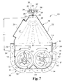
- FIG. 7 is a partial sectional view of the mixer taken along section line 7 — 7 of FIG. 6 .
- FIG. 8 is a partial, top view of the manifold shown in FIGS. 6 and 7.
- FIG. 9 is a partial cutaway, side view of a mixer system of still another embodiment of the present invention with selected internal features diagrammatically shown in phantom.
- FIG. 10 is a cross sectional view of the mixer of FIG. 9 taken along the section line 10 — 10 of FIG. 9 .
- FIG. 11 is another cross sectional view of the mixer of FIG. 9 taken along the section line 11 — 11 of FIG. 9 .
- FIG. 12 is an end elevational view of the mixer of FIG. 9 taken along the view line 12 — 12 of FIG. 9 .
- FIG. 13 is another end elevational view of the mixer of FIG. 9 taken along the view line 13 — 13 of FIG. 9 .
- FIG. 14 is a schematic diagram of the system of FIG. 9 .
- FIG. 1 depicts a colorant mixing system 10 of the present invention.
- system 10 a number of wood chips 12 are transported by conveyer 14 in a direction along arrow I to mixer 60 .
- the chips 12 enter chamber 70 of mixer 60 through inlet 72 and are processed therein. This processing includes mixing with a water-based colorant from liquid mixing subsubsystem 20 .
- Processed wood chips 16 exit through outlet 74 of mixer 60 and are carried away by conveyer 18 in a direction along arrow O.
- Subsystem 20 combines concentrated colorant from source 22 with water from water supply 24 to provide a liquid mixture for delivery to chamber 70 via conduit 26 .
- source 22 includes a vessel holding an ample supply of the concentrated colorant.
- Source 22 may include a plurality of vessels or a colorant dispensing sub-system.
- Water supply 24 is preferably a well water source or city water source of a conventional type.
- Subsystem 20 includes control panel 30 with a display 32 indicating the rate colorant is being delivered for mixing. This rate may be continuously adjusted by an operator with rotary control 34 .
- Control panel 30 also includes a control key pad 33 , a master start switch 36 , and a master stop switch 37 . Switches 36 , 37 start and stop subsystem 20 , respectively.
- control panel 30 has switch 38 corresponding to water supply 24 and switch 39 corresponding to colorant source 22 .
- Each switch 38 , 39 has three positions: on, off, and automatic (or “auto”). When each switch 38 , 39 is in the auto position, subsystem 20 operates normally. The on/off positions are used to separately start and stop water or colorant, respectively, for calibration purposes.
- Subsystem 20 is also operatively coupled to sensor 35 .
- Sensor 35 provides a stop signal corresponding to the absence of material on conveyer 14 . This stop signal is then used to halt subsystem 20 .
- Sensor 35 may be a microswitch with an actuation arm positioned above conveyer 14 a selected distance. This arm is configured to either open or close the microswitch when material on conveyor 14 of a selected height no longer contacts it. Opening or closing of this microswitch sends the corresponding stop signal.
- Other types of sensors as would occur to one skilled in the art are also contemplated.
- Controller 31 is operatively coupled to display 32 , key pad 33 , rotary control 34 , sensor 35 and switches 36 , 37 , 38 , and 39 to coordinate and supervise operation of subsystem 20 .
- Controller 31 may be an electronic circuit comprised of one or more components.
- controller 31 may be comprised of digital circuitry, analog circuitry, or both.
- controller 31 may be programmable, an integrated state machine, or a hybrid combination thereof.
- controller 31 is microprocessor with a known construction and has a control program loaded in non-volatile memory.
- a microcontroller/keyboard combination is supplied as Durant Model No. 5881-5 with part no. 5881-5-400 by Eaton Corporation of Waterloo, Wis., 53094.
- Controller 31 is also coupled to pump system 40 .
- Pump system 40 includes positive cavity control pump 41 coupled to source 22 and driven by motor 42 .
- Controller 31 provides a delivery signal to motor 41 corresponding to a selected rate of delivery of concentrated colorant input to controller 31 with rotary control 34 .
- controller 31 responds to a stop signal from sensor 35 to generate a delivery signal which shuts down pump system 40 .
- This delivery signal may alternatively be characterized as a “shut down” signal.
- valves, 26 a, 26 b The colorant output by pump 41 encounters valves, 26 a, 26 b. Under usual operating conditions, valve 26 a is open and valve 26 b is closed so that colorant flows through check valve 43 . Check valve 43 generally maintains “one way” flow of colorant away from pump 41 . Colorant from check valve 43 empties into joining conduit 48 . During calibration of pump system 40 , valve 26 a is closed, and valve 26 b is open so that colorant flows through calibration outlet 27 for collection and possible reuse. Besides pump system 40 , other metering devices as would occur to one skilled in the art are also contemplated.
- Controller 31 is also operatively coupled to on/off valve 44 having inlet 44 a in fluid communication with water supply 24 , and outlet 44 b for supplying water therefrom.
- Valve 44 is responsive to a signal from controller 31 to correspondingly start or stop water flow from supply 24 .
- controller 31 responds to a stop signal from sensor 35 to shut down water supply 24 by closing valve 44 via a shut down signal.
- Valve 44 may be a conventional solenoid activated stop valve.
- Outlet 44 b of valve 44 is in fluid communication with inlet 46 a of flow regulator 46 .
- Flow regulator 46 has outlet 46 b in fluid communication with check valve 47 .
- Check valve 47 maintains water flow away from flow regulator 46 to joining conduit 48 .
- Flow regulator 46 maintains a generally constant flow rate of water. despite varying pressures at inlet 46 a and/or outlet 46 b. Accordingly, flow regulator 46 adjusts to maintain a generally constant pressure differential between inlet 46 a and outlet 46 b.
- Flow regulator 46 has an adjustable orifice to correspondingly select the regulated rate of flow from a given range of flow rates.
- model no. JB11T-BDM from W. A. Kates, Co., 1450 Jarvis Avenue, Ferndale, Mich. 48220 is used for flow regulator 46 to provide a desired water flow rate selected from between 3 and 80 gallons per minute.
- a different flow regulator may be used or a flow regulator may not be used at all.
- static inline liquid mixer 50 provides a substantially homogenous liquid mixture of concentrated colorant diluted by water which is not generally provided by a conduit of generally constant internal cross-section.
- Concentrated colorant and water enter static liquid mixer 50 through inlet 50 a and exit through outlet 50 b.
- Static liquid mixer 50 is preferably made from a transparent PVC material so that blending cavity 51 therein may be observed.
- blending cavity 51 Within blending cavity 51 are a number of interconnected internal baffles 52 . Baffles 52 are arranged to split the stream of liquid entering through inlet 50 a and force it to opposite outside walls of mixer 50 . A vortex is created axial to the center line of mixer 50 by the arrangement of baffles 52 .
- the vortex is sheared and the process reoccurs but with opposite rotation several times along the length of static liquid mixer 50 .
- This clockwise/counterclockwise motion mixes the liquid to provide a substantially homogenous mixture through outlet 50 b and into conduit 26 .
- static liquid mixer 50 operates without moving internal parts other than the liquid being mixed. This homogenous premixed liquid enhances uniform coloring of wood chips.
- Cole-Parmer Instrument Company of Niles, Ill. 60714 provides a PVC static liquid mixer model no. H-04669-59 for one embodiment of the present invention.
- a static mixing cavity arranged to promote mixing without internal baffles may be used.
- U.S. Pat. No. 4,516,524 to McClellan et al. is cited as a source of additional information concerning a dedicated static mixing cavity of this type.
- premixing of colorant and water prior to entry into chamber 70 is not necessary.
- a desired concentration of water based colorant mixture may be selected.
- This concentration, and the rate of flow of the mixture to chamber 70 of mixer 60 may be matched to the rate of transport of wood chips therethrough to optimize colorant system 10 performance.
- the minimum amount of water necessary to provide uniform coloration for the wood chips may be determined by taking into account the absorbency of the liquid by the wood chips 12 , the rate of flow of the liquid into chamber 70 , and the rate of passage of wood chips 12 through mixer 60 .
- the rate of liquid flow can be adjusted with flow regulator 46 and with rotary control 34 , and the ratio of water to colorant can likewise be adjusted to assure a concentration which will provide uniform coloration.
- the rate of liquid flow can be adjusted with flow regulator 46 and with rotary control 34 , and the ratio of water to colorant can likewise be adjusted to assure a concentration which will provide uniform coloration.
- an adjustable flow rate and colorant delivery rate permits re-optimization of the process when various parameters change; including, but not limited to, a different colorant type, different wood chip delivery rate, or different type of wood chips.
- controller 31 may also be used for a variety of record keeping functions, such as maintaining a record of the amount of colorant dispensed over a given period of time. The amount dispensed may be displayed or otherwise accessed by an operator using keypad 33 . Controller 31 may be configured to provide an operator preferred parameters for flow regulator 46 and metering of colorant with pump system 40 via display 32 and keypad 33 . Also, it may be configured to assist the operator with adjustments relating to different wood chip types, sizes, or delivery rates. In this embodiment, the speed of conveyer 14 may also be sensed with controller 31 to ascertain optimum liquid mixture parameters of subsystem 20 .
- controller 31 may control speed of conveyer 14 or 18 , or otherwise be coupled to mixer 60 to control various operational aspects thereof.
- control panel 30 , controller 31 , display 32 , control 34 , and switches 36 , 37 , 38 , 39 are embodied in a ruggedized personal computer customized with appropriate hardware and software to controllably interface with the other components of subsystem 20 and including a conventional video display and keyboard.
- operator control via controller 31 is provided over the rate of water flow to the mixture instead of colorant.
- colorant concentration is regulated by adjusting the amount of water with controller 31 , and the colorant flow is kept generally constant.
- both water supply 24 and source 22 are operatively coupled to controller 31 to provide dynamic adjustment over the relative flow rate and amount of from each.
- more than two sources of liquid components may be operatively coupled to controller 31 to provide a desired liquid mixture.
- Delivery system 30 may also be used to control delivery of various other mixtures of liquid agents or mixing components. Also, besides wood chips, other solid pieces may be treated with a given liquid mixture from subsystem 20 in mixer 60 . For example, a high gloss transparent coating on certain types of landscaping rocks or gravel may also be provided with system 10 . Preferably, this clear coat is provided by a mixture of water and an organic-based polymer component.
- cinder pieces are colored with system 10 in place of wood chips 12 .
- the cinder pieces can include one or more of slag, fly ash, and/or clinkers, just to name a few.
- at least a portion of the cinder pieces each have a maximum dimension of at least one inch.
- Mixer 60 includes enclosure 61 defining chamber 70 .
- Enclosure 61 is elongated and has end 61 a opposing end 61 b along its length.
- Enclosure 61 has top 62 opposing base 64 .
- Opposing sides 66 and 68 join top 62 and base 64 .
- Top 62 defines inlet 72 and grated observation window 76 .
- Preferably, top 62 is provided by panels which may be removed to gain access to chamber 70 for maintenance purposes.
- Base 64 defines discharge outlet 74 .
- FIG. 3 specifically, internal transverse support members 77 a, 77 b are shown in cross-section.
- Members 77 a, 77 b include a square cross-section and are preferably manufactured from carbon steel.
- support flange 78 is illustrated between ends 61 a and 61 b of enclosure 61 .
- Adjacent end 61 a, 62 b is a right angle bearing flange 79 a, 79 b which supports mixer 60 .
- FIGS. 1, 3 and 4 illustrate a spray manifold 80 .
- Spray manifold 80 is in fluid communication with spray nozzles 82 a, 82 b, 82 c (collectively designated nozzles 82 ). In other embodiments, more or less nozzles may be used.
- Nozzles 82 are in fluid communication with chamber 70 .
- Manifold 80 has intake 84 configured to receive liquid through conduit 26 for distribution within manifold 80 to nozzles 82 . Excess liquid within chamber 70 may be drained through drain holes 88 a, 88 b, as particularly illustrated in FIGS. 3 and 4. Drain holes 88 a and 88 b are typically plugged during operation of mixer 60 .
- FIG. 4 a cross-section of chamber 70 is shown. Also, protruding end flange 86 a is illustrated with a number of attachment sights 87 along its periphery. End flange 86 a is joined to bearing flange 79 a using conventional methods. A similar structure at end 61 b is formed with end flange 86 b and bearing flange 79 b. At the bottom of chamber 70 is a triangular partition 89 .
- enclosure 61 and manifold 80 are manufactured from a metallic material, such as carbon steel; however, other materials as occur to one skilled in the art are also contemplated.
- FIGS. 1, 3 , and 5 depict various features of drive mechanism 90 .
- Drive mechanism 90 includes motor 92 mounted to enclosure 61 by support 94 .
- drive mechanism 90 includes drive box 100 and gear box 110 .
- motor 92 is electrically powered, but other types of prime movers can be employed, such as a gasoline-fueled internal combustion engine.
- a shaft from motor 92 extends into drive box 100 and is connected to sprocket 102 therein.
- Sprocket 102 is operatively coupled to sprocket 104 by drive chain 106 .
- Sprocket 104 is attached to auger 120 by coupling shaft 129 b at the end of auger 120 closest to end 61 b of enclosure 61 .
- An opposing end of auger 120 is attached to coupling shaft 129 a which extends into gear box 110 .
- gear wheel 112 is coupled to coupling shaft 129 a and intermeshes with gear wheel 114 coupled to coupling shaft 149 a.
- Shaft 149 a is coupled to auger 140 at the end of auger 140 closest to end 61 a of enclosure 61 .
- coupling shaft 149 b is coupled thereto.
- Coupling shafts 129 a, 149 a are rigidly attached to shafts 122 , 142 , respectively, and are journaled to enclosure 61 at end 61 a by appropriate bearings.
- Coupling shafts 129 b, 149 b are rigidly attached to shafts 122 , 142 and are journaled to enclosure 61 at end 61 b by appropriate bearings.
- Auger 120 includes a shaft 122 generally oriented along the length of enclosure 61 .
- Attached to auger 120 is helical or spiral flight 124 .
- Flight 124 is configured to turn about shaft 122 in a counterclockwise direction as it advances from end 61 a toward end 61 b.
- flight 124 makes at least three revolutions about shaft 122 .
- flight 124 makes at least five revolutions about shaft 122 .
- flight 124 makes at least nine revolutions about shaft 122 .
- the pitch angle of flight 124 is at least 45°. More preferably, the pitch angle of flight 124 is in the range of 65° to 80°. Most preferably, the pitch angle of flight 124 is about 75°.
- pitch angle means the angle formed between a tangent to an edge of the helical flight and the rotational axis of the flight.
- FIG. 3 illustrates a pitch angle of flight 124 as angle A.
- the pitch angle of flight 124 varies, with a portion closest to end 61 a having a different pitch angle than the rest of flight 124 . In other embodiments, the pitch angle varies in a different fashion or is generally constant.
- auger 120 includes mixing paddles 125 interposed along flight 124 .
- Each mixing paddle 125 is attached to shaft 122 by fastener 127 .
- Each fastener 127 has bolt 127 a extending through shaft 122 and secured thereto by nut 127 b. By loosening nut 127 b, the pitch of mixing paddle 125 relative to flight 124 may be adjusted. Nut 127 b is then re-tightened to secure the newly selected paddle pitch.
- mixing paddles 125 do not extend as far from shaft 122 as flight 124 .
- auger 140 include mixing paddles distributed along shaft 142 which are interposed with flight 144 (not shown).
- each mixing paddle has a portion extending from shaft 122 that has a generally planar sector shape. This sector shape sweeps about a 40 degree angle between radii extending from axis R 1 .
- auger 140 is similarly configured for this embodiment.
- auger 120 also has a reverse spiral flight 128 spaced apart from flight 124 by gap 126 along shaft 122 .
- flight 128 turns around axis R 1 at least 180 degrees. More preferably, flight 128 turns about axis R 1 at least 330 degrees. Most preferably, flight 128 turns about axis R 1 approximately 360 degrees or makes about one revolution around shaft 122 (including axis R 1 ) between flight 124 and end 61 b. Flight 128 advances in a direction from end 61 a to 61 b with a clockwise spiral rotation. Thus, the rotational direction of flight 128 is opposite the rotational direction of flight 124 .
- shaft 122 along gap 126 is flightless.
- the length of gap 126 along shaft 122 is preferably about the length of flight 124 along shaft 122 corresponding to one revolution about shaft 122 .
- Gap 126 and flight 128 both partially overlap or overhang outlet 74 so that at least a portion of flight 128 is positioned over outlet 74 .
- Auger 140 is configured similar to auger 128 except the rotational orientation of the flighting is reversed. Specifically, helical flight 144 of auger 140 turns about shaft 142 in a clockwise direction as it advances from end 61 a to end 61 b. Flight 148 turns about shaft 142 in a counterclockwise direction as it advances in a direction from end 61 a toward end 61 b. Augers 120 and 140 preferably intermesh a slight amount as most clearly depicted in FIG. 4 . This intermeshing is accomplished by slightly offsetting the maximum extension point of the flights relative to each other.
- FIG. 4 illustrates additional characteristics of flight 124 , 144 .
- Shaft 122 has a maximum cross-sectional dimension (M) perpendicular to the plane of view of FIG. 4, and flight 124 has a distance D extending from shaft 122 along this plane.
- M is determined as the maximum cross-sectional dimension of the shaft for its given shape along a cross-sectional plane perpendicular to its rotational axis.
- D is determined as the distance the flight extends from the shaft along an axis perpendicular to the rotational axis of the shaft.
- shafts 122 , 144 each have a generally right cylindrical shape, presenting an approximate circular cross-section perpendicular to rotational axes R 1 , R 2 ; and flights 124 , 128 , 144 , 148 present a generally circular cross-section along a plane perpendicular to the rotational axes R 1 , R 2 of the shafts 122 , 142 , respectively.
- FIGS. 1-5 selected operational features of mixer 60 are next discussed.
- Solid pieces such as wood chips 12
- motor 92 turns sprocket 102 which rotates sprocket 104 via chain 106 .
- Rotation of sprocket 104 turns auger 120 about rotational axis R 1 in the direction RD 1 , driving auger 120 in a counterclockwise or “left hand” direction.
- Rotational axes R 1 , R 2 are shown in FIG. 4 as cross-hair points generally concentric with the cross-section of shafts 122 , 142 , respectively. Notably, these axes are generally parallel to each other and are parallel to the longitudinal axis of augers 120 , 140 , and enclosure 61 .
- auger 120 turns gear wheel 112 contained in gear box 110 .
- Gear wheel 112 rotates gear wheel 114 in response in the opposite direction.
- auger 140 rotates along with gear wheel 114 in a clockwise or “right hand” direction indicated by arrow RD 2 .
- Rotation of flights 124 , 144 of auger 120 , 140 about axes R 1 , R 2 provides an “archimedes screw” type of conveyer which transports solid pieces entering inlet 72 along the direction indicated by arrow F, from end 61 a toward end 61 b.
- flights 124 , 144 move material along arrow F
- flights 124 , 144 also tumble and intermix the solid pieces with a liquid colorant mixture sprayed into chamber 70 via nozzles 82 .
- the liquid mixture is supplied by subsystem 20 to manifold 80 .
- the mixing of the liquid and solid pieces continues as it travels past manifold 80 and by window 76 along arrow F.
- Mixing paddles 125 assist intermixing by agitating the mixture of solid pieces and liquid.
- mixing paddles 125 are pitched to oppose the flow of material along arrow F; and thereby enhance mixing.
- the pitch of mixing paddles 125 relative to flight 124 the average dwell time in chamber 70 of a given material may be changed. This feature further assists in controlling application of the liquid mixture to the solid pieces to minimize run-off of excess liquid.
- processed wood chips 16 begin to exit through outlet 74 to be carried away by conveyer 18 in a direction indicated by arrow O.
- Mixer 60 may be used with a variety of liquid mixture types for coating or adhering a desired substance to solid pieces.
- mixer 60 is used so that the direction of the flow along arrow F is generally horizontal.
- mixer 60 may be inclined in varying amounts as would occur to one skilled in the art.
- FIGS. 6 and 7 depict mixing system 210 of another embodiment of the present invention; where certain reference numerals are the same as those used in connection with system 10 and are intended to represent like features.
- System 210 includes liquid dispensing subsystem 225 , spray hood 250 , and mixer 260 .
- Subsystem 225 includes liquid mixing subsystem 20 .
- subsystem 20 is controller-based and regulates the blending of a mixture of an agent from source 22 with water from supply 24 .
- the regulation and control processes implemented with subsystem 20 also apply to system 210 .
- Liquid dispensing subsystem 225 also includes pump 240 with a liquid inlet to receive the liquid mixture provided by subsystem 20 via conduit 26 .
- Pump 240 increases pressure or pressurizes the mixture received from subsystem 20 .
- Conduit 226 is in fluid communication with a liquid outlet of pump 240 and spray hood 250 .
- Pump 240 delivers the pressurized mixture to spray hood 250 via conduit 226 .
- pump 240 is arranged to provide the liquid mixture with a pressure in a range of about 200 to 400 pounds per square inch (psi). In other embodiments, pump 240 can provide a different pressure or is absent.
- Mixer 260 is coupled to spray hood 250 and includes a mixing trough 261 extending along its longitudinal axis L with opposing ends 261 a, 261 b. Trough 261 is partially covered by top 262 . Top 262 is opposite base 264 . Trough 261 is bounded by opposing side walls 266 , 268 and defines a mixing passage 270 . Trough 261 has inlet 272 defined through top 262 adjacent end 261 a and outlet 274 defined through base 264 adjacent end 261 b. Inlet 272 and outlet 274 intersect passage 270 . Inlet 272 and outlet 274 are separated from each other along axis L by distance LD 1 .
- Augers 120 , 140 Disposed within passage 270 are augers 120 , 140 .
- Augers 120 , 140 extend from inlet 272 to outlet 274 and are turned by drive mechanism 90 with motor 92 via drive box 100 and gear box 110 as described in connection with mixer 60 of system 10 .
- Augers 120 , 140 have shafts 122 , 142 and helical flights 124 , 144 , respectively, as previously described.
- a space 223 is defined between flight 124 and shaft 122 except at the ends 225 , 227 which are connected to shaft 122 .
- Space 223 corresponds to a cross-section along axis L having a generally circular outer and inner contour bounded by flight 124 and shaft 122 , respectively.
- a like space is preferably defined between flight 144 and shaft 142 of auger 140 .
- space 223 extend between shaft 122 and flight 124 for a distance corresponding to at least three revolutions of flight 124 about shaft 122 . More preferably, this distance corresponds to at least six revolutions of flight 124 about shaft 122 .
- flight 124 is separated from shaft 122 and does not make contact therewith, defining space 223 therebetween, except where connected at ends 225 and 227 .
- FIG. 6 depicts flight 128 overlapping outlet 274 with an opposite rotational direction relative to flight 124 .
- Flight 124 is separated from flight 128 by a flightless gap 126 along shaft 122 .
- auger 140 has a second flight sized and positioned like flight 128 with a rotational direction opposite flight 144 as described in connection with system 10 .
- the second flights 128 , 148 for each auger 120 , 140 respectively, have been found to reduce clogging at outlet 274 .
- augers 120 , 140 preferably include adjustable mixing paddles 125 . Paddles 125 may be utilized to adjust dwell time of products being mixed in trough 261 .
- Spray hood 250 defines chamber 252 and has a hinged access door 254 to facilitate maintenance as is best depicted in FIG. 7 .
- Manifold 280 is connected to the top of hood 250 and includes a number of spray nozzles 282 for delivering the liquid from subsystem 20 to chamber 252 via supply conduit 284 .
- Supply conduit 284 is in fluid communication with conduit 226 to receive the pressurized mixture from pump 240 .
- brackets 283 support conduit 284 along hood 250 above nozzles 282 .
- Conduit 284 terminates in end cap 284 a.
- each nozzle 282 have a spray pattern SP that subtends an angle A.
- angle A is at least 60 degrees. More preferably, angle A is at least 80 degrees.
- One preferred nozzle 282 is model no. USS8060 provided by Spraying Systems Company having a business address of P. O. Box 7900, Wheaton, Ill. 60189-7900. This model is of the VEEJET line and sprays about 6 gallons per minute when supplied liquid at a pressure of about 40 lbs. per square inch (psi).
- at least 8 nozzles are utilized. More preferably, at least 12 nozzles are utilized as depicted in FIG. 6 .
- conduit 284 of manifold 280 includes a four-way conduit junction 286 for every four nozzles 282 .
- Each junction 286 is in fluid communication with two valves 287 on opposite sides thereof.
- Each valve 287 is in fluid communication with a “T” junction coupling 288 .
- a hose 289 is coupled to each opposite end of coupling 288 to a corresponding valve 290 in fluid communication with one of nozzles 282 .
- three junctions 286 , six valves 287 , and six “T” junction couplings 288 are utilized.
- chamber 252 is defined by a metal enclosure and door 254 is similarly formed from metal.
- conduit 284 of manifold 280 is preferably formed from a two-inch diameter PVC pipe and junctions 286 are each provided as a four-way two-inch PVC connector.
- Valves 287 and 290 are of a half-inch variety and may be adjusted by hand.
- transition members/reducers are used between values 287 and corresponding junctions 286 .
- Couplings 288 are likewise formed from PVC and hoses 289 are of a standard reinforced rubber type for this embodiment.
- Area CA has a length LD 2 along the distance LD 1 as shown in FIG. 6 .
- distance LD 2 is at least about half of distance LD 1 .
- distance ID 2 is at least two-thirds of distance LD 1 .
- Augers 120 , 140 occupy a maximum width across passage 270 below spray hood 250 represented as width W 1 in FIG. 7 .
- W 1 is the maximum transverse distance across axis L collectively occupied by augers 120 , 140 .
- Area CA preferably has a width that is at least one-half the width W 1 . More preferably, the width of area CA is at least about three-fourths of the width W 1 . Most preferably, the width of area CA is substantially all of width W 1 as shown FIG. 7 .
- nozzles 282 are spaced at intervals along axis L to provide a collective spray pattern along distance LD 2 .
- the spray pattern has a length of at least about one-half of distance 1 LD 1 and a width at least about one-half of width W 1 . More preferably, the length of the spray pattern along axis L is at least about two-thirds the distance LD 1 and a maximum width of at least about three-fourths of width W 1 .
- the spray pattern has a length generally the same as distance LD 2 that is greater than or equal to about two-thirds of the distance LD 1 and a width that is substantially all of the width W 1 at a number of intervals along the distance LD 2 .
- nozzles 282 be separated from augers 120 , 140 by a height of at least one-half W 1 to facilitate dispersal of the liquid from subsystem 20 in chamber 252 before contacting solid pieces being carried through passage 270 .
- mixer 260 is configured to accept solid pieces through inlet 272 which are then advanced along passage 270 towards outlet 274 in the direction indicated by arrow F by turning augers 120 , 140 with drive mechanism 90 . As the pieces are advanced with augers 120 , 140 , they are tumbled and intermixed facilitating coating, coloring, or another mixing process with a liquid introduced through spray hood 250 .
- the pieces passing through mixer 260 may be, for example, wood chips of a suitable size and consistency for use as a mulch and the liquid delivered with subsystem 20 may be a mixture of a liquid colorant and water to impart a desired color to the wood chips.
- valves 287 , 290 may be adjusted to provide a desired spray pattern within chamber 252 with nozzles 282 .
- each valve 290 may be adjusted to selectively reduce or shut-off the spray from the nozzle 282 coupled thereto.
- Valves 287 may each be used to shut-off or adjust flow to each respective pair of nozzles 282 coupled thereto via a corresponding coupling 288 , pair of hoses 289 , and pair of valves 290 .
- valves 287 are used to make coarse adjustments and valves 290 are used to make fine adjustments.
- these nozzles are electronically controlled by a controller to establish various predetermined patterns (not shown).
- the expansive spray pattern of system 210 facilitates a reduction in water usage needed in order to color wood chips to provide a suitable mulch with a generally uniform color. It is believed this reduction in water consumption results because the amount of chip surface area contacted by the color-imparting spray is greater than with existing systems, so that the amount of color-imparting liquid that needs to freely flow in trough 261 to properly color the wood chips is comparatively less.
- the claimed invention be limited to any stated mechanism or theory.
- system 210 is used to color wood chips provided in a consistency suitable for application as a mulch; however, in another embodiment, a scent is additionally supplied in order to simulate a known type of mulch such as eucalyptus, cedar, or pine.
- scent may be dispensed in a liquid form from a separate system comparable to subsystem 20 and may be introduced into chamber 252 through one or more nozzles 282 instead of the colorant mixture.
- the scent may be homogeneously mixed with colorant and water before being dispensed to hood 250 , or a single vessel containing concentrated liquid colorant and scent that has been premixed may be mixed with water in subsystem 20 and subsequently supplied to hood 250 .
- system 210 may be used with a variety of liquid mixture types for coating or adhering a desired substance to solid pieces.
- solid pieces other than wood chips may be processed in this manner, such as rocks, cardboard, synthetic resin pieces, and the like.
- color is imparted to cinder pieces with system 210 .
- These pieces can include slag, fly ash and/or clinkers, to name just a few.
- at least a portion of the cinder pieces have a maximum dimension of one inch or greater.
- mixer 260 generally can be maintained in a horizontal position during use, in other embodiments, trough 261 may be inclined in varying amounts as would occur to one skilled in the art.
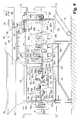
- FIG. 9 depicts mixer system 400 of another embodiment of the present invention.
- System 400 can be used in a wide variety applications in which it is desirable to mix solid pieces and a liquid.
- Such applications include, but are not limited to, the treatment of wood chips, rocks, cinders, rubber, glass, and/or comminuted paper products with a liquid to impart coloration, a translucent or transparent coating, and/or a scent to the pieces; or the treatment of landfill material with landfill leachate as described in the commonly owned U.S. Patent Application entitled “Landfill Operation Techniques and Solid/Liquid Mixing Systems” filed on May 31, 2000.
- System 400 includes conveyer 18 , as previously described in connection with system 10 , and mixer 301 .
- Mixer 301 includes body 355 defining mixing chamber 356 with inlet 352 and outlet 354 . More particularly, body 355 of mixer 301 is elongate, having a first end 363 a opposing a second end 363 b along axis R, which extends along the length of body 355 .
- Mixer 301 is further designated as having first section 303 along a first segment of axis R and second section 305 along a second segment of axis R.
- Inlet 352 is disposed between the first end 363 a and outlet 354 and intersects chamber 356 along a top portion of body 355 .
- Chamber 356 is configured to receive solid pieces through inlet 352 with the assistance of gravity.
- Inlet 352 is further defined by funnel/hopper member 353 , which is sized to contain a desired volume of solid pieces to be processed with mixer 301 .
- Outlet 354 is defined in the bottom portion of body 355 .
- inlet 352 and/or outlet 354 can be formed partially or completely through a respective end 363 a, 363 b or a lateral side portion of body 355 , or can be otherwise oriented as would occur to those skilled in the art.
- System 400 also includes liquid dispensing subsystem 325 .
- Liquid dispensing subsystem 325 includes pump 340 and liquid supply 440 .
- Supply 440 is further described in connection with FIG. 14 hereinafter.
- Conduit 326 couples supply 440 to an inlet of pump 340 to supply a liquid.
- Pump 340 is arranged to increase the liquid pressure.
- pump 340 provides a liquid pressure in a range of about 200 to about 400 psi. In other embodiments, the pressure provided by pump 340 can differ, or pump 340 can be absent. From pump 340 , the pressurized liquid exits through an outlet in fluid communication with supply conduit 367 .
- Supply conduit 367 provides the pressurized liquid to liquid input ports 368 .
- Ports 368 are in the form of spray nozzles arranged to provide a desired spray pattern for the controlled application of liquid to solid pieces in chamber 356 .
- Liquid source conduit 367 is positioned over mixing chamber 356 to supply liquid to a distribution manifold that passes through hood 366 b to ports 368 .
- Ports 368 are positioned beneath hood 366 b as depicted in FIG. 9 .
- Hood 366 b and ports 368 are positioned above chamber 356 at a location between inlet 352 and outlet 354 .
- subsystem 325 is arranged with a spray hood and manifold configuration the same as that of system 210 previously described.
- Mixer 301 also includes conveying/mixing subsystem 360 to move the solid pieces introduced into inlet 352 of the first section 303 to outlet 354 of second section 305 , and to mix liquid from subsystem 325 with these pieces.
- System 360 includes rotary conveying member 360 a in section 303 and rotary conveying member 360 b in section 305 .
- Members 360 a, 360 b are each disposed within chamber 356 along axis R.
- rotary conveying member 360 a includes shaft 364 a and rotary conveying member 360 b includes shaft 364 b.
- Shaft 364 a of member 360 a has opposing ends 461 a, 461 b and shaft 364 b of member 360 b has opposing ends 463 a, 463 b.
- Rotary conveying member 360 a aligns with rotary conveying member 360 b in an end-to-end relationship such that end 461 b and end 463 a are closer together than ends 461 a and 463 b.
- Members 360 a, 360 b also include structures 361 that extend from the respective shafts 364 a and 364 b to advance solid pieces from inlet 352 to outlet 354 as shafts 364 a and 364 b are each rotated about axis R in a designated rotational direction (clockwise or counterclockwise).
- structures 361 can include spiral threading, paddles, flights, or the like affixed to shafts 364 a, 364 b. It should be understood that the orientation of the extending structures determines the direction of travel of pieces along axis R for a given rotational direction of shaft 364 a, 364 b; such that the rotational direction that advances the pieces could be same for each member 360 a, 360 b or different.
- structures 361 include adjustable-pitch paddles 365 a and fixed-pitch paddles 365 b that each radially extend from shaft 364 a about axis R.
- Paddles 365 a each include base 367 a fixed to shaft 364 a and adjustable paddle member 369 a extending from base 367 a.
- Base 367 a has sleeve 373 a fixed thereto.
- Member 369 a includes coupling rod 371 a that engages sleeve 373 a of base 367 a.
- Rod 371 a is selectively fixed to base 367 a by one or more set screws (not shown) threaded through one or more corresponding openings in sleeve 373 a to adjustably contact rod 371 a.
- Reference numerals 367 a, 369 a, 371 a, and 373 a are designated for only one of paddles 365 a in FIG. 9 to preserve clarity.
- the pitch of each member 369 a of each paddle 365 a can be angularly adjusted by loosening the corresponding set screw(s), positioning rod 371 a within sleeve 373 a to locate member 369 a as desired, and retightening the set screw(s).
- Fixed-pitch paddles 365 b alternate with adjustable-pitch paddles along axis R.
- Paddles 365 a, 365 b are spaced apart from one another along axis R, and are also angularly spaced apart from one to the next about axis R.
- the angular spacing about axis R between a given pair of paddles 365 a, 365 b is approximately 52 degrees, such that paddles 365 a, 365 b follow a generally helical path about axis R.
- the pitch of each of paddles 365 b is approximately 45 degrees.
- the type of adjustable paddle 365 a can differ, the pitch of paddles 365 b can differ from one another or have a different common pitch; the angular spacing of the paddles 365 a, 365 b along and/or about axis R can differ; there can be more or fewer paddles 365 a and/or 365 b; and/or different types of extending structures such as threading or flighting can be employed.
- Structures 361 for rotary conveying member 360 b include a number of pitch-adjustable paddles 365 c and a number of flights 362 a, 362 b, 362 c.
- Paddles 365 c each radially extend from shaft 364 b about axis R.
- Paddles 365 c each include base 367 b fixed to shaft 364 b and adjustable paddle member 369 b extending from base 367 b.
- Base 367 b has sleeve 373 b fixed thereto.
- Member 369 b includes coupling rod 371 b that engages sleeve 373 b of base 367 b.
- Rod 371 b is selectively fixed to base 367 b by one or more set screws (not shown) threaded through one or more corresponding openings in sleeve 373 b to adjustably contact rod 371 b.
- Reference numerals 367 b, 369 b, 371 b, and 373 b are designated for only one of paddles 365 c in FIG. 9 to preserve clarity.
- the pitch of each member 369 b of each paddle 365 c can be angularly adjusted by loosening the corresponding set screw(s), positioning rod 37 lb within sleeve 373 b to locate member 369 b as desired, and retightening the set screw(s).
- flight 362 a is positioned adjacent end 463 a on shaft 364 b at generally the same distance along axis R as one of paddles 365 c.
- flight 362 b is positioned on shaft 364 b with another paddle 365 c at an approximately common distance along axis R adjacent outlet 354 .
- Flight 362 b is positioned between flight 362 a and 362 c and partially extends over outlet 354 .
- groups of paddles 365 c are positioned at generally regular intervals of distance along shaft 364 b and axis R. At each interval, the members of the corresponding group of paddles are angularly spaced apart from one another by approximately 320 degrees.
- Flight 362 c extends over a portion of outlet 354 opposite flight 362 d and is adjacent end 363 b of mixer 301 . Flight 362 c is oriented with a rotational direction opposite that of flights 362 a, 362 b to reduce the likelihood of clogs in the vicinity of outlet 354 . As depicted, flights 362 a, 362 b, 362 c each occupy approximately a 320 degree sector about axis R.
- the rotational direction and/or amount of revolution(s) a flight has about axis R can differ; the type of paddle can differ; the angular spacing between paddles about axis R can differ; there can be more or fewer paddles and/or flights; and/or other types of structures for rotary conveying member 360 b can be utilized.
- a shelf 370 is attached to body 355 in section 303 of chamber 356 , thereby providing a raised platform in section 303 .
- paddles 365 a, 365 b have a smaller radial extension from shaft 364 a than do paddles 365 c from shaft 364 b.
- mixer 301 does not include a shelf, and paddles in section 303 can generally have the same length as paddles in section 305 .
- Coupling support member 311 carries a pair of journal bearings 310 a, 310 b.
- Journal bearing 310 a is engaged by coupling shaft 374 a that extends from end 461 b of shaft 364 a and journal bearing 310 b is engaged by coupling shaft 374 b that extends from end 463 a of shaft 364 b to rotatably couple shafts 364 a and 364 b to support member 311 .
- Shafts 364 a and 364 b are also journaled at ends 363 a and 363 b of body 355 , respectively.
- at least a portion of one of ends 461 b, 463 a can include a recess sized and shaped to receive the other of ends 461 b, 463 a in a rotational bearing relationship.
- a different journaling arrangement is utilized as would occur to those skilled in the art.
- Members 360 a and 360 b can have a wide variety of lengths, and the coupling support member 311 can be positioned in a wide variety of locations relative to other components of mixer 301 . As depicted, ends 461 b and 463 a meet between inlet 352 and outlet 354 . As members 360 a and 360 b are rotated to move material through chamber 356 , they share a generally common rotational and longitudinal axis coincident with axis R.
- drive mechanisms 458 a, 458 b are operable to be independently and selectively rotated at different rates by drive mechanisms 458 a, 458 b, respectively. Furthermore, drive mechanisms 458 a, 458 b are arranged to optionally reverse rotational direction of members 360 a, 360 b as will be more fully described hereinafter.
- drive mechanisms 458 a, 458 b include drivers 358 a, 358 b with drive sheaves 359 a, 359 b, respectively.
- Drive sheaves 359 a, 359 b are rotatably coupled to sheaves 459 a, 459 b by corresponding drive belts 470 a, 470 b.
- this rotary coupling can be provided by meshed gears, a chain and sprocket arrangement, a clamming arrangement, frictionally engaged rollers, a combination of these, or such other arrangement as would occur to those skilled in the art.
- Sheaves 459 a, 459 b have rotational centers 465 a, 465 b, respectively.
- the rotational centers of shafts 364 a, 364 b are coincident with axis R, which is perpendicular to the view plane of FIGS. 12 and 13, and therefore designated by cross-hairs. It should be understood that rotational centers 465 a, 465 b are each offset from axis R.
- Reducers 480 a and 480 b rotatably couple sheaves 459 a and 459 b to shafts 364 a and 364 b, respectively.
- Reducers 480 a, 480 b provide a reduction in the rate of rotation of the respective shafts 364 a, 364 b relative to the speed of corresponding sheaves 459 a, 459 b. Indeed, members 360 a and 360 b can be rotated at different rates by using reducers 480 a and 480 b with different turn ratios.
- drivers 358 a, 358 b are each in the form of an electric motor.
- the drivers 358 a, 358 b can be in the form of an internal combustion engine, a hydraulic motor, a steam driven turbine, a pneumatic motor or another type of prime mover as would occur to a person of ordinary skill in the art.
- a common source of rotational mechanical power such as a single electric motor, is used to drive members 360 a and 360 b. In this embodiment (not shown), the motor engages two drive shafts, one extending beyond end 363 a of mixer 301 , and the other extending beyond end 363 b of mixer 301 .
- sheave 359 a At a position along one drive shaft generally planar to sheave 459 a, sheave 359 a is attached. A belt drives sheave 459 a with sheave 359 a as described above. At a position along the other drive shaft generally planar to sheave 459 b, sheave 359 b is attached. Another belt drives sheave 459 b with sheave 359 b as described above.
- one of drive mechanisms 458 a or 458 b is modified to turn a drive shaft that extends along the length of body 355 and terminates in a sheave to power a drive mechanism at the opposite end. In this manner, a single source of rotational mechanical power can be used to drive both rotary conveying members.
- different drive linkages or devices are used, or one or more of shafts 364 a, 364 b are directly driven by a driver.
- Liquid supply 440 is further illustrated with source 22 , supply 24 , pump 427 , and liquid mixer 50 ; where like reference numerals refer to like features of subsystem 20 previously described.
- An inlet of pump 427 is coupled to source 22 to selectively meter colorant for mixing with water from supply 24 .
- Liquid mixer 50 blends the water and colorant constituents to provide a more uniform consistency of the resulting mixture.
- the mixture output by mixer 50 is supplied to conduit 326 for delivery to pump 340 to be pressurized as previously described in connection with FIG. 9 .
- Liquid supply 440 can include valves, regulators and other structures of subsystem 20 to facilitate colorant/water mixing.
- subsystem 325 can include other dispensing equipment, liquid mixers, regulators, and valves as would occur to those skilled in the art.
- liquid supplied with subsystem 325 requires no mixing prior to delivery.
- driver 430 for conveyor belt 18 is illustrated that may be controlled to move discharged pieces away from outlet 354 after processing by mixer 301 . Also schematically illustrated are drivers 358 a, 358 b of mechanisms 458 a, 458 b of mixer 301 .
- System 400 further includes control subsystem 402 and operator control panel 404 .
- Control subsystem 402 is operatively coupled to drivers 358 a, 358 b, 430 , and pumps 340 , 427 to selectively control the operation thereof in response to one or more input signals from control panel 404 .
- Control panel 404 is arranged in a number of columns 406 a, 406 b, 406 c, 406 d, 406 e of operator controls and indicators that correspond to operation of rotary conveying member 360 b (labeled “mixing”), pump 427 (labeled “pump”), rotary conveying member 360 a (labeled “feeding”), conveyor 18 (labeled “belt”), and pump 340 (labeled “mixture pump”) respectively.
- Each column 406 a - 406 e includes an indicator light 407 that is illuminated when the corresponding driver or pump is active.
- a start/stop toggle push button 408 Located below the respective indicator light 407 of each column 406 a - 406 e, is a start/stop toggle push button 408 .
- start/stop toggle push button 408 alternatively activates and deactivates the corresponding driver 358 a, 358 b, 430 or pump 340 , 427 when it is depressed and released.
- speed controls 410 Located below pushbuttons 408 in each column 406 a-e 06 d are speed controls 410 in the form of rotary knobs. Rotation of controls 410 adjusts speed of the corresponding drivers 358 a, 358 b, 430 or pump 427 between a predetermined minimum and maximum through control subsystem 402 .
- a momentary pushbutton 412 is also included.
- Subsystem 402 responds to the depression of pushbutton 412 to cause the corresponding driver 358 a or 358 b to turn in a reverse rotational direction for as long as the momentary pushbutton 412 remains depressed. This “reverse jog” operation is helpful to address clogging and/or jamming of mixer 301 .
- Meter 418 of control panel 404 displays a numeric value corresponding to the rate of delivery of colorant being metered with pump 427 .
- Meter 418 can be of an LED, LCD, or other type as would occur to those skilled in the art.
- Control panel 404 further includes an emergency stop button (labeled “E-stop”) to halt all operations of drivers 358 a, 358 b, 430 and pumps 340 , 427 and send an alarm via horn 416 .
- E-stop an emergency stop button
- Control subsystem 402 is configured to cause drivers 358 a, 358 b, 430 and pumps 340 , 427 to respond to operator manipulation of the controls of panel 404 in the manner described.
- Control subsystem 402 can be comprised of a collection of components or configured as a single integral unit. When of a multi-component form, controller 402 may have one or more components remotely located relative to the others, or otherwise have its components distributed throughout system 400 .
- Subsystem 402 can include circuitry that is programmable, arranged as a state logic machine or other type of dedicated hardware, or configured as a hybrid combination of programmable and dedicated hardware. When such circuitry is involved, it can be of a digital variety, analog variety, or both.
- subsystem 402 may include one or more mechanical, hydraulic, pneumatic, or optical elements.
- Control subsystem 402 includes any interface/control circuits or elements necessary to interface with drivers 358 a, 358 b, 430 , and pumps 340 , 427 .
- drivers 358 a, 358 b are in the form of electric motors
- corresponding variable speed motor control circuitry is included in subsystem 402 .
- control subsystem 402 also includes a programmable, integrated circuit-based processor with appropriate digital memory capacity.
- the processor is programmed to generate appropriate control signals for the driver and/or pump interfaces of subsystem 402 in response to input signals from the controls of panel 404 .
- solid pieces are introduced into mixer 301 through inlet 352 .
- rotary conveying member 360 a rotates to move the introduced pieces from inlet 352 to rotary conveying member 360 b of section 305 .
- Liquid is introduced into chamber 356 in the vicinity of section 305 to be intermixed with the solid pieces.
- Rotary conveying member 360 b also continues to move the pieces to outlet 354 for discharge and subsequent removal by conveyor 70 . Because liquid is introduced in section 305 , section 303 primarily operates as a feeder of the pieces and section 305 primarily operates to intermix the pieces and liquid, and discharge the mixture.
- feeding and mixing can be generally exclusive to one or more rotary conveying members, or both can be performed with a given rotary conveying member.
- rotary conveying member 360 a rotates at a rotational speed that is in a range of 40% to 80% of the rotational speed of rotary conveying member 360 b.
- rotary conveying member 360 a has a maximum rotational speed of about 40 revolutions per minute (RPM) and rotary conveying member 360 b has a maximum rotational speed of about 300 RPM.
- RPM revolutions per minute
- the relative speed differences between two or more rotary conveying members can otherwise differ or be the same.
- paddles 365 a, 365 b can be arranged, sized, and adjusted to provide feeder action while paddles 365 c and flights 362 b and 362 c can be arranged, sized, and adjusted to provide a desired mixing action in addition to or as an alternative to moving the pieces along axis R. Indeed, in one alternative embodiment it is desirable to angle one or more paddles in a manner that tends to reverse the direction of advancing pieces to increase dwell time. In addition, paddles and flights in contact with the mixture can be configured to ameliorate clogging.
- a “rotary conveying member” broadly refers to any member that rotates to move solid pieces in contact therewith, including, but not limited to any member that rotates to move such pieces in a generally common direction, to move one or more of such pieces in different directions, and/or to change the direction of motion of one or more of such pieces.
- liquid can also reach pieces in section 303 , such that rotary conveying member 360 a can also perform solid/liquid mixing; however, shelf 370 tends to limit the amount of liquid backflow. Instead, liquid tends to accumulate in the bottom of section 305 .
- one or more rotary conveying members include flights
- the flights can be spaced apart from the shaft or such spaces may be absent. Flights can alternatively or additionally extend along a majority of the length of either rotary conveying member as in the case of auger 60 of mixer 41 .
- one or more of the rotary conveying members are configured as a conventional screw conveyor with continuous helical flighting.
- flights may be configured as previously described in connection with systems 10 or 210 .
- speed of rotary conveying member 360 a and/or 360 b can be automatically controlled based upon feedback from one or more sensors (not shown).
- sensors can be used, for example, to continuously or periodically detect the volumetric flow rate of the solid pieces, to detect the amount of liquid being introduced into the system, to detect the amount of liquid being collected from the system that does not adhere to or become absorbed in the solid pieces, and/or to detect the presence of solid pieces being introduced into mixer 301 and/or removed by conveyor 70 .
- sensors may be absent. Indeed, subsystem 402 and/or control panel 404 can be absent, instead providing for adjustability of the driver or pump directly.
- the rate of only one of drivers 358 a, 358 b is adjustable.
- operator inputs and outputs may be provided by other devices in addition or as an alternative to those described in connection with control panel 404 , including, but not limited to push buttons, levers, or slides to adjust operating speeds, keyboard entered commands, or graphical user interface (GUI) controls, just to name a few.
- GUI graphical user interface
- subsystem 402 can also be used for a variety of record keeping functions, such as maintaining a record of the amount of liquid dispensed with pump 427 or volume of solid pieces passing through mixer 301 over a given period of time.
- Subsystem 402 can also be configured to provide an operator preferred parameters for motor speed and liquid introduction rate. Also, it can be configured to assist the operator with adjustments relating to different wood chip types, sizes, or delivery rates, when wood chips are being processed in mixer 301 .
- subsystem 402 and control panel 404 are embodied, at least in part, in a ruggedized personal computer customized with appropriate hardware and software to controllably interface with other components of mixer 301 and including a conventional graphic video display and keyboard (not shown) to facilitate operator input and output.
- mixer 301 can be utilized to mix a wide variety of solid pieces 42 with a wide variety of liquids as would be contemplated by one of skill in the art.
- various colorants and/or high gloss transparent or translucent coatings such as, for example, polymer coatings, can be applied to certain types of landscaping rocks or gravel in accordance with the invention.
- mixer 301 is utilized to impart colorant and/or scent to wood chips for the production of landscaping mulch.
- colorant and/or scent is applied to cinders to provide a form of landscaping rock.
- at least a portion of the cinder pieces each have a maximum dimension of one inch or more.
- the conveying/mixing system includes two independently driven rotary conveying members disposed within the chamber that do not share a common rotational axis.
- rotary conveying members may be arranged along parallel rotational axes or the rotational axis may be set at an angle with respect to one another.
- the shafts of the two rotary conveying members overlap, extending past one another in a parallel or angled configuration.
- a conveying/mixing system includes more than two independently driven rotary conveying members disposed within the chamber and aligned to move material from one member to the next.
- the rotary conveying members can be positioned to rotate around a generally common rotational axis or offset in a parallel or angled arrangement.
- a mixing system is provided that includes different sets of multiple rotary conveying members operable to turn at different speeds. In one example of such an embodiment, the sets are arranged to be generally parallel to one another.
- Another embodiment of the present invention includes providing a number of solid pieces to an inlet of a mixer that includes a chamber intersecting the inlet and an outlet intersecting the chamber; introducing a liquid into the chamber between the inlet and the outlet; and rotating two rotary conveying members at different speeds within the chamber to move the solid pieces from the inlet towards the outlet and intermix the solid pieces with the liquid.
- a first one of the rotary conveying members moves the solid pieces from the inlet to a second one of the rotary conveying members and the second one of the rotary conveying members discharges the solid pieces through the outlet. It should be understood that one or both of the rotary conveying members can perform the intermixing of the pieces and liquid, and that one or both of the rotary conveying members moves solid pieces towards the outlet.
- Still another embodiment of the present invention includes: introducing wood pieces into a mixing chamber through an inlet, where the chamber includes an outlet spaced apart from the inlet; providing a liquid to the chamber including a colorant; rotating a first rotary conveying member disposed within the chamber at a first rotational speed to move the wood pieces from the inlet to a second rotary conveying member disposed within the chamber; rotating the second rotary conveying member at a second rotational speed different from the first rotational speed to move the wood pieces; and discharging the pieces through the outlet.
- Yet a further embodiment includes providing solid pieces to a mixing chamber through an inlet that is spaced apart from a chamber outlet.
- a liquid is provided to the chamber for mixing with the solid pieces.
- An rotary conveying member is disposed within the chamber to move the solid pieces from the inlet toward the outlet when rotated in a first rotational direction.
- a control is provided to rotate the rotary conveying member in a second rotational direction opposite the first rotational direction to address clogging of the mixing chamber.
- the solid pieces can be in the form of wood chips and the liquid can include a colorant.
Abstract
Description
Claims (8)
Priority Applications (1)
| Application Number | Priority Date | Filing Date | Title |
|---|---|---|---|
| US09/592,478 US6517232B1 (en) | 1996-05-20 | 2000-06-09 | Mixing systems |
Applications Claiming Priority (3)
| Application Number | Priority Date | Filing Date | Title |
|---|---|---|---|
| US08/650,871 US5866201A (en) | 1996-05-20 | 1996-05-20 | Solid/liquid rotational mixing system |
| US09/231,691 US6162496A (en) | 1996-05-20 | 1999-01-14 | Method of mixing |
| US09/592,478 US6517232B1 (en) | 1996-05-20 | 2000-06-09 | Mixing systems |
Related Parent Applications (1)
| Application Number | Title | Priority Date | Filing Date |
|---|---|---|---|
| US09/231,691 Continuation-In-Part US6162496A (en) | 1996-05-20 | 1999-01-14 | Method of mixing |
Publications (1)
| Publication Number | Publication Date |
|---|---|
| US6517232B1 true US6517232B1 (en) | 2003-02-11 |
Family
ID=43706141
Family Applications (1)
| Application Number | Title | Priority Date | Filing Date |
|---|---|---|---|
| US09/592,478 Expired - Lifetime US6517232B1 (en) | 1996-05-20 | 2000-06-09 | Mixing systems |
Country Status (1)
| Country | Link |
|---|---|
| US (1) | US6517232B1 (en) |
Cited By (33)
| Publication number | Priority date | Publication date | Assignee | Title |
|---|---|---|---|---|
| US20050039651A1 (en) * | 2003-08-21 | 2005-02-24 | International Environmental Solutions Corpora | Variable speed pyrolytic waste treatment system |
| US20060058601A1 (en) * | 2004-08-11 | 2006-03-16 | Smith Chad A | System and method for translating medical imaging system patient tables |
| US20070140051A1 (en) * | 2005-12-16 | 2007-06-21 | Perkins Dennis R | Mixing system for thermoset compositions including static and rotary mixers |
| US20070186829A1 (en) * | 2003-08-21 | 2007-08-16 | International Environmental Solutions Corporation | Variable speed pyrolytic waste treatment system |
| US20090097351A1 (en) * | 2007-10-16 | 2009-04-16 | Wing Chung Li | Programmable Electronic Hand Mixer |
| US20100108774A1 (en) * | 2008-11-05 | 2010-05-06 | Miller Alan T | Apparatus and methods for treating mulch in situ |
| US20100229461A1 (en) * | 2009-03-11 | 2010-09-16 | Becker-Underwood, Inc. | Coating for and method of testing landscaping material |
| US20100263322A1 (en) * | 2009-04-20 | 2010-10-21 | Rule Kenneth P | Method for Fabricating Environmentally Friendly Shakes |
| US20110086228A1 (en) * | 2009-10-08 | 2011-04-14 | Becker Underwood, Inc. | Green-Colored Environmentally Inert Coated Materials, Barrier Compositions and Related Methods |
| US20120021094A1 (en) * | 2010-01-22 | 2012-01-26 | Gregory Dean Sunvold | Process for Making a Pet Food in the Form of a Coated Kibble |
| US20130051173A1 (en) * | 2010-01-28 | 2013-02-28 | Bühler AG | Mixer Comprising a Deflector Surface |
| CN104324654A (en) * | 2014-09-10 | 2015-02-04 | 南通密炼捏合机械有限公司 | Special receiving apparatus for ball valve blanking and discharging kneader |
| US20180369762A1 (en) * | 2016-03-15 | 2018-12-27 | Halliburton Energy Services, Inc. | Mulling device and method for treating bulk material released from portable containers |
| US10195572B2 (en) * | 2014-12-03 | 2019-02-05 | Bakery Concepts International, Llc | Mixing chamber |
| US10259140B1 (en) * | 2018-10-19 | 2019-04-16 | Red Dog Mobile Shelters, Llc | Portable concrete mixer for hydrating and mixing concrete mix containing gravel aggregate in a continuous process |
| US10919693B2 (en) | 2016-07-21 | 2021-02-16 | Halliburton Energy Services, Inc. | Bulk material handling system for reduced dust, noise, and emissions |
| US11047717B2 (en) | 2015-12-22 | 2021-06-29 | Halliburton Energy Services, Inc. | System and method for determining slurry sand concentration and continuous calibration of metering mechanisms for transferring same |
| US11066259B2 (en) | 2016-08-24 | 2021-07-20 | Halliburton Energy Services, Inc. | Dust control systems for bulk material containers |
| US11186318B2 (en) | 2016-12-02 | 2021-11-30 | Halliburton Energy Services, Inc. | Transportation trailer with space frame |
| US11186452B2 (en) | 2015-11-25 | 2021-11-30 | Halliburton Energy Services, Inc. | Sequencing bulk material containers for continuous material usage |
| US11186431B2 (en) | 2016-07-28 | 2021-11-30 | Halliburton Energy Services, Inc. | Modular bulk material container |
| US11186454B2 (en) | 2016-08-24 | 2021-11-30 | Halliburton Energy Services, Inc. | Dust control systems for discharge of bulk material |
| US11192731B2 (en) | 2015-05-07 | 2021-12-07 | Halliburton Energy Services, Inc. | Container bulk material delivery system |
| US11192077B2 (en) | 2015-07-22 | 2021-12-07 | Halliburton Energy Services, Inc. | Blender unit with integrated container support frame |
| US11273421B2 (en) | 2016-03-24 | 2022-03-15 | Halliburton Energy Services, Inc. | Fluid management system for producing treatment fluid using containerized fluid additives |
| US11285639B2 (en) * | 2020-01-30 | 2022-03-29 | Red Dog Mobile Shelters, Llc | Portable mixer for hydrating and mixing cementitious mix in a continuous process |
| US11311849B2 (en) | 2016-03-31 | 2022-04-26 | Halliburton Energy Services, Inc. | Loading and unloading of bulk material containers for on site blending |
| US11338260B2 (en) | 2016-08-15 | 2022-05-24 | Halliburton Energy Services, Inc. | Vacuum particulate recovery systems for bulk material containers |
| US11388914B2 (en) | 2015-04-28 | 2022-07-19 | Mars, Incorporated | Process of preparing a wet pet food, wet pet food produced by the process and uses thereof |
| US11395998B2 (en) | 2017-12-05 | 2022-07-26 | Halliburton Energy Services, Inc. | Loading and unloading of material containers |
| US11498037B2 (en) | 2016-05-24 | 2022-11-15 | Halliburton Energy Services, Inc. | Containerized system for mixing dry additives with bulk material |
| US11535986B2 (en) | 2017-08-30 | 2022-12-27 | Douglas Dynamics, Llc | Spreader |
| US11814242B2 (en) | 2015-07-22 | 2023-11-14 | Halliburton Energy Services, Inc. | Mobile support structure for bulk material containers |
Citations (68)
| Publication number | Priority date | Publication date | Assignee | Title |
|---|---|---|---|---|
| US649232A (en) | 1898-08-20 | 1900-05-08 | Hugo Berger | Process of impregnating down with powdered rosin. |
| US1735393A (en) | 1924-07-07 | 1929-11-12 | Stanley Hiller Inc | Apparatus for treating materials |
| US1948871A (en) | 1930-04-07 | 1934-02-27 | Strong Mfg Co Scott | Feed mixing machine |
| US2620173A (en) * | 1948-12-15 | 1952-12-02 | Minnie A White | Machine for making hot tamales and similar food products |
| US2702018A (en) | 1952-01-07 | 1955-02-15 | Benjamin F Gustafson | Seed treating machine |
| GB1099941A (en) | 1964-07-28 | 1968-01-17 | Bahre Metallwerk K G | Device for coating chips with glue |
| US3421740A (en) | 1966-10-31 | 1969-01-14 | Norman A Behrens | Material mixer |
| US3583680A (en) * | 1967-10-05 | 1971-06-08 | Aust Und Schuttler & Co M A S | Mixing and discharging apparatus for fillers and binders |
| US3705851A (en) | 1971-11-15 | 1972-12-12 | Robert C Brauer | Waste disposal system |
| US3732697A (en) | 1972-01-14 | 1973-05-15 | R Dickson | Waste disposal method and facility |
| US3734471A (en) | 1970-11-24 | 1973-05-22 | Draiswerke Gmbh | Device for continuous mixing of solids with liquids |
| US3779518A (en) * | 1971-02-11 | 1973-12-18 | Agfa Gevaert Ag | Continuous photographic emulsion processing |
| US3841102A (en) | 1974-01-02 | 1974-10-15 | Environmental Sciences Inc | Method of improving the quality of leachate from sanitary landfills |
| US3856278A (en) | 1972-10-07 | 1974-12-24 | Werner & Pfleiderer | Twin-screw extruder with adjustable throttling means |
| DE2428588A1 (en) | 1974-06-14 | 1976-01-02 | Loedige | DEVICE FOR GLUEING SPAEN |
| US3968771A (en) | 1974-05-23 | 1976-07-13 | Chevron Research Company | Process and apparatus for applying pesticides to granular materials |
| US4014286A (en) | 1975-04-25 | 1977-03-29 | Zurik Donald E De | Hot product marking system |
| US4015830A (en) | 1974-07-17 | 1977-04-05 | Loedige Wilhelm | Apparatus for applying glue to chips, fibers and the like |
| US4025058A (en) | 1975-08-14 | 1977-05-24 | Dai Nippon Toryo Co., Ltd. | Continuous extruder for thermosetting resins |
| US4067140A (en) | 1976-04-07 | 1978-01-10 | Thomas John C | Mulch and process of making same |
| US4079696A (en) | 1975-09-22 | 1978-03-21 | Gustafson, Inc. | Apparatus for treating seeds with a liquid |
| US4107787A (en) | 1976-03-26 | 1978-08-15 | Werner & Pfleiderer | Screw extruder for continuously processing and degasing of elastomers and polymers having a viscosity of more than 1,000 poise |
| US4188130A (en) | 1977-10-04 | 1980-02-12 | Draiswerke Gmbh | Device for continuously mixing wood chips with binder |
| US4202636A (en) | 1977-01-26 | 1980-05-13 | Phillips Petroleum Company | Mixing device with internal recycle |
| US4232480A (en) | 1979-05-14 | 1980-11-11 | Conwed Corporation | Method and device for coloring bulk hydro mulch fibers |
| US4290702A (en) | 1979-12-17 | 1981-09-22 | Scientific Process & Research, Inc. | Plasticating apparatus for molding devices |
| US4323367A (en) | 1980-06-23 | 1982-04-06 | Institute Of Gas Technology | Gas production by accelerated in situ bioleaching of landfills |
| US4370945A (en) | 1980-04-25 | 1983-02-01 | Gebruder Lodige Maschinenbau Gesellschaft mit beschrankter Haftung | Method for gluing of particles containing chips, fibers and similar ligno-cellulose-containing particles and apparatus for this purpose of gluing the same |
| US4387997A (en) | 1979-12-17 | 1983-06-14 | Scientific Process & Research, Inc. | Plasticating extruder screw conveyors |
| US4390285A (en) | 1980-08-24 | 1983-06-28 | Draiswerke Gmbh | Method and apparatus for mixing solids with liquids, in particular for gluing wood chips |
| US4396402A (en) | 1980-06-23 | 1983-08-02 | Institute Of Gas Technology | Gas production by accelerated bioleaching of organic materials |
| US4429043A (en) | 1982-01-05 | 1984-01-31 | Biorganic Energy Inc. | Anaerobic digestion of organic waste for biogas production |
| US4460292A (en) | 1982-07-15 | 1984-07-17 | Agritec, Inc. | Process for containment of liquids as solids or semisolids |
| US4474852A (en) | 1983-05-23 | 1984-10-02 | Thomas B. Crane | Hydrophobic colloidal oxide treated core material, method of production and composition comprised thereof |
| US4491522A (en) | 1982-11-18 | 1985-01-01 | Agency Of Industrial Science & Technology | Anaerobic digestion process for organic wastes |
| US4514090A (en) | 1982-03-12 | 1985-04-30 | Werner And Pfleiderer | Apparatus for processing viscous substances or substances which become viscous through processing |
| US4516524A (en) | 1983-02-16 | 1985-05-14 | The Upjohn Company | Apparatus for coating particulate material |
| US4518507A (en) | 1983-09-13 | 1985-05-21 | Chem-Technics, Inc. | Method for chemically solidifying and encapsulating hazardous wastes in one continuous operation |
| US4527902A (en) | 1983-02-08 | 1985-07-09 | Draiswerke Gmbh | Methods and mixers for the continuous addition of glue to mixtures consisting of wood chips, wood fibres or the like |
| US4559142A (en) | 1983-02-17 | 1985-12-17 | Linde Aktiengesellschaft | Split feed for the anaerobic biological purification of wastewater |
| US4560479A (en) | 1979-11-07 | 1985-12-24 | Gist-Brocades N.V. | Process for preparing biomass attached to a carrier |
| US4586459A (en) | 1984-04-12 | 1986-05-06 | Gean Agricultural Manufacturing Ltd. | Liquid chemical applicator |
| US4681457A (en) | 1985-05-14 | 1987-07-21 | Kabushiki Kaisha Kobe Seiko Sho | Continuous mixer |
| US4897196A (en) | 1988-02-17 | 1990-01-30 | Zimpro/Passavant Inc. | Two-stage batch wastewater treatment |
| US4932156A (en) | 1988-11-09 | 1990-06-12 | Becker-Underwood, Inc. | Method of controlling the color of mulch |
| US4935211A (en) | 1989-01-23 | 1990-06-19 | Azar David G | Fluorogypsum waste solidification material |
| US4987850A (en) | 1988-06-06 | 1991-01-29 | Ciba-Geigy Corporation | Apparatus for the wetting of seeds |
| US5028299A (en) | 1987-06-23 | 1991-07-02 | Gilbert Guidat | Installation for the continuous-flow production of stabilized chips or particles derived from wood waste |
| US5105577A (en) | 1991-04-19 | 1992-04-21 | Hedges Gary W | Artificial mulch chips |
| US5114083A (en) | 1988-06-10 | 1992-05-19 | Kubota, Ltd. | Method and appatatus for pulverizing material |
| US5139365A (en) | 1990-09-04 | 1992-08-18 | Warren Chesner | Process for waste injection into landfills for waste management, landfill reclamation, enhanced biodegradation and enhanced methane gas generation and recovery |
| US5192587A (en) | 1991-08-23 | 1993-03-09 | Kurtz Bros., Inc. | Method for coloring wood chips |
| US5238633A (en) | 1991-05-24 | 1993-08-24 | Duraplast Corporation | Method and apparatus for recycling plastic waste into a thin profile, mechanically reinforced board |
| US5246310A (en) | 1992-07-16 | 1993-09-21 | Steve Washuta | Process for producing a landfill |
| US5266256A (en) | 1993-02-16 | 1993-11-30 | Rohm And Haas Company | Extruder and process modifying residence time distribution |
| US5267788A (en) | 1992-01-31 | 1993-12-07 | Farrel Corporation | Multi-screw, continuous mixing and kneading machine with polygonal kneading elements for plasticizable compounds |
| US5354127A (en) | 1990-04-10 | 1994-10-11 | William Del Zotto | Segmented mixing auger |
| US5358738A (en) | 1993-03-31 | 1994-10-25 | Sawka Craig S | Method and apparatus for painting the surfaces of wood chips |
| US5358331A (en) * | 1986-02-27 | 1994-10-25 | John William Cruse | Blending device for particulate material, with helical conveyer |
| US5372459A (en) | 1992-07-16 | 1994-12-13 | Steve Washuta | Process for producing a landfill |
| US5401534A (en) | 1992-03-17 | 1995-03-28 | Rhone-Poulenc Agrochimie | Process and apparatus for continuous treatment of particles |
| US5486327A (en) * | 1994-01-21 | 1996-01-23 | Bemis Manufacturing Company | Apparatus and method for injecting or extruding colored plastic |
| US5562956A (en) | 1995-06-07 | 1996-10-08 | White, Jr.; Haves R. | Wood chipping and dyeing processes and products thereof |
| US5569811A (en) | 1994-10-06 | 1996-10-29 | Dean; Miles W. | Method for isolating, immobilizing and rendering waste non-leachable |
| US5630944A (en) | 1992-06-10 | 1997-05-20 | Terblanche; Johannes S. | Treatment of sewage sludge |
| US5866201A (en) | 1996-05-20 | 1999-02-02 | Blue; David | Solid/liquid rotational mixing system |
| US5895511A (en) | 1997-12-22 | 1999-04-20 | Futuristic Tile, L.L.C. | Method of producing a decorative construction material |
| US6321804B1 (en) * | 2000-04-08 | 2001-11-27 | Mangold Recycling Inc. | Process for grinding and coloring wood chips |
-
2000
- 2000-06-09 US US09/592,478 patent/US6517232B1/en not_active Expired - Lifetime
Patent Citations (71)
| Publication number | Priority date | Publication date | Assignee | Title |
|---|---|---|---|---|
| US649232A (en) | 1898-08-20 | 1900-05-08 | Hugo Berger | Process of impregnating down with powdered rosin. |
| US1735393A (en) | 1924-07-07 | 1929-11-12 | Stanley Hiller Inc | Apparatus for treating materials |
| US1948871A (en) | 1930-04-07 | 1934-02-27 | Strong Mfg Co Scott | Feed mixing machine |
| US2620173A (en) * | 1948-12-15 | 1952-12-02 | Minnie A White | Machine for making hot tamales and similar food products |
| US2702018A (en) | 1952-01-07 | 1955-02-15 | Benjamin F Gustafson | Seed treating machine |
| GB1099941A (en) | 1964-07-28 | 1968-01-17 | Bahre Metallwerk K G | Device for coating chips with glue |
| US3421740A (en) | 1966-10-31 | 1969-01-14 | Norman A Behrens | Material mixer |
| US3583680A (en) * | 1967-10-05 | 1971-06-08 | Aust Und Schuttler & Co M A S | Mixing and discharging apparatus for fillers and binders |
| US3734471A (en) | 1970-11-24 | 1973-05-22 | Draiswerke Gmbh | Device for continuous mixing of solids with liquids |
| US3779518A (en) * | 1971-02-11 | 1973-12-18 | Agfa Gevaert Ag | Continuous photographic emulsion processing |
| US3705851A (en) | 1971-11-15 | 1972-12-12 | Robert C Brauer | Waste disposal system |
| US3732697A (en) | 1972-01-14 | 1973-05-15 | R Dickson | Waste disposal method and facility |
| US3856278A (en) | 1972-10-07 | 1974-12-24 | Werner & Pfleiderer | Twin-screw extruder with adjustable throttling means |
| US3841102A (en) | 1974-01-02 | 1974-10-15 | Environmental Sciences Inc | Method of improving the quality of leachate from sanitary landfills |
| US3968771A (en) | 1974-05-23 | 1976-07-13 | Chevron Research Company | Process and apparatus for applying pesticides to granular materials |
| DE2428588A1 (en) | 1974-06-14 | 1976-01-02 | Loedige | DEVICE FOR GLUEING SPAEN |
| US4006706A (en) | 1974-06-14 | 1977-02-08 | Loedige Wilhelm | Device for applying glue to chips |
| US4015830A (en) | 1974-07-17 | 1977-04-05 | Loedige Wilhelm | Apparatus for applying glue to chips, fibers and the like |
| US4014286A (en) | 1975-04-25 | 1977-03-29 | Zurik Donald E De | Hot product marking system |
| US4025058A (en) | 1975-08-14 | 1977-05-24 | Dai Nippon Toryo Co., Ltd. | Continuous extruder for thermosetting resins |
| US4079696A (en) | 1975-09-22 | 1978-03-21 | Gustafson, Inc. | Apparatus for treating seeds with a liquid |
| US4107787A (en) | 1976-03-26 | 1978-08-15 | Werner & Pfleiderer | Screw extruder for continuously processing and degasing of elastomers and polymers having a viscosity of more than 1,000 poise |
| US4067140A (en) | 1976-04-07 | 1978-01-10 | Thomas John C | Mulch and process of making same |
| US4202636A (en) | 1977-01-26 | 1980-05-13 | Phillips Petroleum Company | Mixing device with internal recycle |
| US4188130A (en) | 1977-10-04 | 1980-02-12 | Draiswerke Gmbh | Device for continuously mixing wood chips with binder |
| US4232480A (en) | 1979-05-14 | 1980-11-11 | Conwed Corporation | Method and device for coloring bulk hydro mulch fibers |
| US4560479A (en) | 1979-11-07 | 1985-12-24 | Gist-Brocades N.V. | Process for preparing biomass attached to a carrier |
| US4290702A (en) | 1979-12-17 | 1981-09-22 | Scientific Process & Research, Inc. | Plasticating apparatus for molding devices |
| US4387997A (en) | 1979-12-17 | 1983-06-14 | Scientific Process & Research, Inc. | Plasticating extruder screw conveyors |
| US4370945A (en) | 1980-04-25 | 1983-02-01 | Gebruder Lodige Maschinenbau Gesellschaft mit beschrankter Haftung | Method for gluing of particles containing chips, fibers and similar ligno-cellulose-containing particles and apparatus for this purpose of gluing the same |
| US4396402A (en) | 1980-06-23 | 1983-08-02 | Institute Of Gas Technology | Gas production by accelerated bioleaching of organic materials |
| US4323367A (en) | 1980-06-23 | 1982-04-06 | Institute Of Gas Technology | Gas production by accelerated in situ bioleaching of landfills |
| US4390285A (en) | 1980-08-24 | 1983-06-28 | Draiswerke Gmbh | Method and apparatus for mixing solids with liquids, in particular for gluing wood chips |
| US4429043A (en) | 1982-01-05 | 1984-01-31 | Biorganic Energy Inc. | Anaerobic digestion of organic waste for biogas production |
| US4514090A (en) | 1982-03-12 | 1985-04-30 | Werner And Pfleiderer | Apparatus for processing viscous substances or substances which become viscous through processing |
| US4460292A (en) | 1982-07-15 | 1984-07-17 | Agritec, Inc. | Process for containment of liquids as solids or semisolids |
| US4491522A (en) | 1982-11-18 | 1985-01-01 | Agency Of Industrial Science & Technology | Anaerobic digestion process for organic wastes |
| US4527902A (en) | 1983-02-08 | 1985-07-09 | Draiswerke Gmbh | Methods and mixers for the continuous addition of glue to mixtures consisting of wood chips, wood fibres or the like |
| US4516524A (en) | 1983-02-16 | 1985-05-14 | The Upjohn Company | Apparatus for coating particulate material |
| US4559142A (en) | 1983-02-17 | 1985-12-17 | Linde Aktiengesellschaft | Split feed for the anaerobic biological purification of wastewater |
| US4474852A (en) | 1983-05-23 | 1984-10-02 | Thomas B. Crane | Hydrophobic colloidal oxide treated core material, method of production and composition comprised thereof |
| US4518507A (en) | 1983-09-13 | 1985-05-21 | Chem-Technics, Inc. | Method for chemically solidifying and encapsulating hazardous wastes in one continuous operation |
| US4586459A (en) | 1984-04-12 | 1986-05-06 | Gean Agricultural Manufacturing Ltd. | Liquid chemical applicator |
| US4681457A (en) | 1985-05-14 | 1987-07-21 | Kabushiki Kaisha Kobe Seiko Sho | Continuous mixer |
| US5358331A (en) * | 1986-02-27 | 1994-10-25 | John William Cruse | Blending device for particulate material, with helical conveyer |
| US5028299A (en) | 1987-06-23 | 1991-07-02 | Gilbert Guidat | Installation for the continuous-flow production of stabilized chips or particles derived from wood waste |
| US4897196A (en) | 1988-02-17 | 1990-01-30 | Zimpro/Passavant Inc. | Two-stage batch wastewater treatment |
| US4987850A (en) | 1988-06-06 | 1991-01-29 | Ciba-Geigy Corporation | Apparatus for the wetting of seeds |
| US5114083A (en) | 1988-06-10 | 1992-05-19 | Kubota, Ltd. | Method and appatatus for pulverizing material |
| US4932156A (en) | 1988-11-09 | 1990-06-12 | Becker-Underwood, Inc. | Method of controlling the color of mulch |
| US4935211A (en) | 1989-01-23 | 1990-06-19 | Azar David G | Fluorogypsum waste solidification material |
| US5354127A (en) | 1990-04-10 | 1994-10-11 | William Del Zotto | Segmented mixing auger |
| US5139365A (en) | 1990-09-04 | 1992-08-18 | Warren Chesner | Process for waste injection into landfills for waste management, landfill reclamation, enhanced biodegradation and enhanced methane gas generation and recovery |
| US5105577A (en) | 1991-04-19 | 1992-04-21 | Hedges Gary W | Artificial mulch chips |
| US5238633A (en) | 1991-05-24 | 1993-08-24 | Duraplast Corporation | Method and apparatus for recycling plastic waste into a thin profile, mechanically reinforced board |
| US5308653A (en) | 1991-08-23 | 1994-05-03 | Kurtz Bros., Inc. | Method for coloring wood chips using a screw conveyor |
| US5192587A (en) | 1991-08-23 | 1993-03-09 | Kurtz Bros., Inc. | Method for coloring wood chips |
| US5267788A (en) | 1992-01-31 | 1993-12-07 | Farrel Corporation | Multi-screw, continuous mixing and kneading machine with polygonal kneading elements for plasticizable compounds |
| US5401534A (en) | 1992-03-17 | 1995-03-28 | Rhone-Poulenc Agrochimie | Process and apparatus for continuous treatment of particles |
| US5630944A (en) | 1992-06-10 | 1997-05-20 | Terblanche; Johannes S. | Treatment of sewage sludge |
| US5246310A (en) | 1992-07-16 | 1993-09-21 | Steve Washuta | Process for producing a landfill |
| US5372459A (en) | 1992-07-16 | 1994-12-13 | Steve Washuta | Process for producing a landfill |
| US5266256A (en) | 1993-02-16 | 1993-11-30 | Rohm And Haas Company | Extruder and process modifying residence time distribution |
| US5358738A (en) | 1993-03-31 | 1994-10-25 | Sawka Craig S | Method and apparatus for painting the surfaces of wood chips |
| US5486327A (en) * | 1994-01-21 | 1996-01-23 | Bemis Manufacturing Company | Apparatus and method for injecting or extruding colored plastic |
| US5569811A (en) | 1994-10-06 | 1996-10-29 | Dean; Miles W. | Method for isolating, immobilizing and rendering waste non-leachable |
| US5643170A (en) | 1994-10-06 | 1997-07-01 | Dean; Miles W. | Method for isolating, immobilizing and rendering waste non-leachable |
| US5562956A (en) | 1995-06-07 | 1996-10-08 | White, Jr.; Haves R. | Wood chipping and dyeing processes and products thereof |
| US5866201A (en) | 1996-05-20 | 1999-02-02 | Blue; David | Solid/liquid rotational mixing system |
| US5895511A (en) | 1997-12-22 | 1999-04-20 | Futuristic Tile, L.L.C. | Method of producing a decorative construction material |
| US6321804B1 (en) * | 2000-04-08 | 2001-11-27 | Mangold Recycling Inc. | Process for grinding and coloring wood chips |
Non-Patent Citations (2)
| Title |
|---|
| "Marion Mixers, Engineered Solutions for Unique Mixing Application Since 1938", http://www.marionmixers.com/co.htm, visited on Aug. 10, 2000. |
| The Revolutionary Second Harvester, Mulch Coloring System, by Becker-Underwood, Inc., Marketing brochure, dated Oct. 1996. * |
Cited By (49)
| Publication number | Priority date | Publication date | Assignee | Title |
|---|---|---|---|---|
| US20070186829A1 (en) * | 2003-08-21 | 2007-08-16 | International Environmental Solutions Corporation | Variable speed pyrolytic waste treatment system |
| US20050039651A1 (en) * | 2003-08-21 | 2005-02-24 | International Environmental Solutions Corpora | Variable speed pyrolytic waste treatment system |
| US20060058601A1 (en) * | 2004-08-11 | 2006-03-16 | Smith Chad A | System and method for translating medical imaging system patient tables |
| US7532922B2 (en) * | 2004-08-11 | 2009-05-12 | General Electric Company | System and method for translating medical imaging system patient tables |
| US8182134B2 (en) | 2005-12-16 | 2012-05-22 | PRC De Soto International, Inc. | Mixing system for thermoset compositions including static and rotary mixers |
| US20070140051A1 (en) * | 2005-12-16 | 2007-06-21 | Perkins Dennis R | Mixing system for thermoset compositions including static and rotary mixers |
| US20090097351A1 (en) * | 2007-10-16 | 2009-04-16 | Wing Chung Li | Programmable Electronic Hand Mixer |
| US8172451B2 (en) * | 2007-10-16 | 2012-05-08 | Arcfl Technology Limited | Programmable electronic hand mixer |
| US20100108774A1 (en) * | 2008-11-05 | 2010-05-06 | Miller Alan T | Apparatus and methods for treating mulch in situ |
| US8361542B2 (en) | 2008-11-05 | 2013-01-29 | Miller Alan T | Apparatus and methods for treating mulch in situ |
| US9113604B2 (en) | 2008-11-05 | 2015-08-25 | Alan T. Miller | Apparatus for treating mulch in situ |
| US20100229461A1 (en) * | 2009-03-11 | 2010-09-16 | Becker-Underwood, Inc. | Coating for and method of testing landscaping material |
| US8764899B2 (en) | 2009-03-11 | 2014-07-01 | Basf Corporation | Coating for and method of testing landscaping material |
| US20100263322A1 (en) * | 2009-04-20 | 2010-10-21 | Rule Kenneth P | Method for Fabricating Environmentally Friendly Shakes |
| US8399060B2 (en) | 2009-04-20 | 2013-03-19 | Lifepine Products, Llc | Method for fabricating environmentally friendly shakes |
| US20110086228A1 (en) * | 2009-10-08 | 2011-04-14 | Becker Underwood, Inc. | Green-Colored Environmentally Inert Coated Materials, Barrier Compositions and Related Methods |
| US20120021094A1 (en) * | 2010-01-22 | 2012-01-26 | Gregory Dean Sunvold | Process for Making a Pet Food in the Form of a Coated Kibble |
| US9585412B2 (en) | 2010-01-22 | 2017-03-07 | Mars, Incorporated | Process for making a pet food in the form of a coated kibble |
| US20130051173A1 (en) * | 2010-01-28 | 2013-02-28 | Bühler AG | Mixer Comprising a Deflector Surface |
| CN104324654A (en) * | 2014-09-10 | 2015-02-04 | 南通密炼捏合机械有限公司 | Special receiving apparatus for ball valve blanking and discharging kneader |
| US10195572B2 (en) * | 2014-12-03 | 2019-02-05 | Bakery Concepts International, Llc | Mixing chamber |
| US10384175B2 (en) | 2014-12-03 | 2019-08-20 | Bakery Concepts International, Llc | Mixing chamber |
| US11388914B2 (en) | 2015-04-28 | 2022-07-19 | Mars, Incorporated | Process of preparing a wet pet food, wet pet food produced by the process and uses thereof |
| US11905132B2 (en) | 2015-05-07 | 2024-02-20 | Halliburton Energy Services, Inc. | Container bulk material delivery system |
| US11192731B2 (en) | 2015-05-07 | 2021-12-07 | Halliburton Energy Services, Inc. | Container bulk material delivery system |
| US11939152B2 (en) | 2015-07-22 | 2024-03-26 | Halliburton Energy Services, Inc. | Mobile support structure for bulk material containers |
| US11814242B2 (en) | 2015-07-22 | 2023-11-14 | Halliburton Energy Services, Inc. | Mobile support structure for bulk material containers |
| US11192077B2 (en) | 2015-07-22 | 2021-12-07 | Halliburton Energy Services, Inc. | Blender unit with integrated container support frame |
| US11203495B2 (en) | 2015-11-25 | 2021-12-21 | Halliburton Energy Services, Inc. | Sequencing bulk material containers for continuous material usage |
| US11186452B2 (en) | 2015-11-25 | 2021-11-30 | Halliburton Energy Services, Inc. | Sequencing bulk material containers for continuous material usage |
| US11047717B2 (en) | 2015-12-22 | 2021-06-29 | Halliburton Energy Services, Inc. | System and method for determining slurry sand concentration and continuous calibration of metering mechanisms for transferring same |
| US11512989B2 (en) | 2015-12-22 | 2022-11-29 | Halliburton Energy Services, Inc. | System and method for determining slurry sand concentration and continuous calibration of metering mechanisms for transferring same |
| US20180369762A1 (en) * | 2016-03-15 | 2018-12-27 | Halliburton Energy Services, Inc. | Mulling device and method for treating bulk material released from portable containers |
| US11192074B2 (en) * | 2016-03-15 | 2021-12-07 | Halliburton Energy Services, Inc. | Mulling device and method for treating bulk material released from portable containers |
| US11273421B2 (en) | 2016-03-24 | 2022-03-15 | Halliburton Energy Services, Inc. | Fluid management system for producing treatment fluid using containerized fluid additives |
| US11311849B2 (en) | 2016-03-31 | 2022-04-26 | Halliburton Energy Services, Inc. | Loading and unloading of bulk material containers for on site blending |
| US11498037B2 (en) | 2016-05-24 | 2022-11-15 | Halliburton Energy Services, Inc. | Containerized system for mixing dry additives with bulk material |
| US11192712B2 (en) | 2016-07-21 | 2021-12-07 | Halliburton Energy Services, Inc. | Bulk material handling system for reduced dust, noise, and emissions |
| US10919693B2 (en) | 2016-07-21 | 2021-02-16 | Halliburton Energy Services, Inc. | Bulk material handling system for reduced dust, noise, and emissions |
| US11186431B2 (en) | 2016-07-28 | 2021-11-30 | Halliburton Energy Services, Inc. | Modular bulk material container |
| US11338260B2 (en) | 2016-08-15 | 2022-05-24 | Halliburton Energy Services, Inc. | Vacuum particulate recovery systems for bulk material containers |
| US11186454B2 (en) | 2016-08-24 | 2021-11-30 | Halliburton Energy Services, Inc. | Dust control systems for discharge of bulk material |
| US11066259B2 (en) | 2016-08-24 | 2021-07-20 | Halliburton Energy Services, Inc. | Dust control systems for bulk material containers |
| US11186318B2 (en) | 2016-12-02 | 2021-11-30 | Halliburton Energy Services, Inc. | Transportation trailer with space frame |
| US11535986B2 (en) | 2017-08-30 | 2022-12-27 | Douglas Dynamics, Llc | Spreader |
| US11395998B2 (en) | 2017-12-05 | 2022-07-26 | Halliburton Energy Services, Inc. | Loading and unloading of material containers |
| US10543620B1 (en) * | 2018-10-19 | 2020-01-28 | Red Dog Mobile Shelters, Llc | Portable concrete mixer for hydrating and mixing concrete mix containing gravel aggregate in a continuous process |
| US10259140B1 (en) * | 2018-10-19 | 2019-04-16 | Red Dog Mobile Shelters, Llc | Portable concrete mixer for hydrating and mixing concrete mix containing gravel aggregate in a continuous process |
| US11285639B2 (en) * | 2020-01-30 | 2022-03-29 | Red Dog Mobile Shelters, Llc | Portable mixer for hydrating and mixing cementitious mix in a continuous process |
Similar Documents
| Publication | Publication Date | Title |
|---|---|---|
| US6517232B1 (en) | Mixing systems | |
| US6536939B1 (en) | Solid/liquid mixing system | |
| US5866201A (en) | Solid/liquid rotational mixing system | |
| US7320539B2 (en) | Concrete batching facility and method | |
| US5401402A (en) | Process and apparatus for treating sewage sludge | |
| CA2503855C (en) | Concrete batching pre-mixer and method | |
| CA1203231A (en) | Apparatus for treating liquid and semi-solid organic waste materials | |
| US5352035A (en) | Concrete mixing system with cement/water premixer | |
| US5556237A (en) | Apparatus and method for dispensing and distributing loose particulate materials | |
| US4232973A (en) | Continuous mixing apparatus for flowable products | |
| US3381943A (en) | Method and apparatus for mixing liquid and solid materials | |
| US858017A (en) | Machine for mixing concrete. | |
| US7281839B1 (en) | Turbine cement/water mixer for concrete production | |
| CA2352008C (en) | Machine for coloring landscaping material | |
| US6491479B1 (en) | Apparatus and method for applying agent to particulate material | |
| US4471916A (en) | Apparatus for treating liquid and semi-solid organic waste materials | |
| DE3465026D1 (en) | Apparatus for mixing and dosing solids | |
| US5470147A (en) | Portable continual mixer | |
| US7478944B2 (en) | Soil mixing apparatus with auger and chemical injection | |
| KR200240254Y1 (en) | A reactor for selectively culturing prokaryote | |
| JPS638417Y2 (en) | ||
| JPH10148033A (en) | Mortar production method in working site and mortar mixer | |
| JPH07521Y2 (en) | Spraying device | |
| KR20100040565A (en) | Rotational delivering device and apparatus for transfering cerment mortar with the same | |
| US1095719A (en) | Food-mixer. |
Legal Events
| Date | Code | Title | Description |
|---|---|---|---|
| AS | Assignment |
Owner name: BECKER-UNDERWOOD, INC., INDIANA Free format text: ASSIGNMENT OF ASSIGNORS INTEREST;ASSIGNOR:WOOD'N COLORS, INC.;REEL/FRAME:012002/0681 Effective date: 20010726 Owner name: BECKER-UNDERWOOD, INC., INDIANA Free format text: ASSIGNMENT OF ASSIGNORS INTEREST;ASSIGNOR:BLUE, DAVID;REEL/FRAME:012043/0088 Effective date: 20010726 |
|
| AS | Assignment |
Owner name: ANTRES CAPITAL CORPORATION, AS AGENT, ILLINOIS Free format text: AMENDMENT TO PATENT SECURITY AGREEMENT;ASSIGNOR:BECKER-UNDERWOOD, INC.;REEL/FRAME:012043/0700 Effective date: 20010727 |
|
| AS | Assignment |
Owner name: WOOD'N COLORS, INC., INDIANA Free format text: CORRECTION OF NOTICE OF RECORDATION OF ASSIGNMENT RECORDED JULY 31, 2001 AT REEL 012043/FRAME 0088; CORRECT NAME OF RECEIVING PARTY IS WOOD'N COLORS, INC.;ASSIGNOR:BLUE, DAVID;REEL/FRAME:013653/0241 Effective date: 20010726 |
|
| STCF | Information on status: patent grant |
Free format text: PATENTED CASE |
|
| AS | Assignment |
Owner name: BECKER-UNDERWOOD, INC., IOWA Free format text: RELEASE AND REASSIGNMENT;ASSIGNOR:ANTARES CAPITAL CORPORATION;REEL/FRAME:015756/0991 Effective date: 20040831 Owner name: BECKER-UNDERWOOD, INC., IOWA Free format text: RELEASE AND REASSIGNMENT;ASSIGNOR:ANTARES CAPITAL CORPORATION;REEL/FRAME:015766/0001 Effective date: 20040831 |
|
| AS | Assignment |
Owner name: ANTARES CAPITAL CORPORATION, ILLINOIS Free format text: SECURITY AGREEMENT;ASSIGNOR:BECKER-UNDERWOOD, INC.;REEL/FRAME:015766/0273 Effective date: 20040831 |
|
| FPAY | Fee payment |
Year of fee payment: 4 |
|
| AS | Assignment |
Owner name: ANTARES CAPITAL CORPORATION, AS COLLATERAL AGENT,I Free format text: SECURITY AGREEMENT;ASSIGNOR:BECKER-UNDERWOOD, INC.;REEL/FRAME:023915/0581 Effective date: 20100120 Owner name: ANTARES CAPITAL CORPORATION, AS COLLATERAL AGENT, Free format text: SECURITY AGREEMENT;ASSIGNOR:BECKER-UNDERWOOD, INC.;REEL/FRAME:023915/0581 Effective date: 20100120 |
|
| FPAY | Fee payment |
Year of fee payment: 8 |
|
| FEPP | Fee payment procedure |
Free format text: PAT HOLDER NO LONGER CLAIMS SMALL ENTITY STATUS, ENTITY STATUS SET TO UNDISCOUNTED (ORIGINAL EVENT CODE: STOL); ENTITY STATUS OF PATENT OWNER: LARGE ENTITY |
|
| SULP | Surcharge for late payment | ||
| AS | Assignment |
Owner name: BECKER-UNDERWOOD, INC., IOWA Free format text: RELEASE BY SECURED PARTY;ASSIGNOR:ANTARES CAPITAL CORPORATION;REEL/FRAME:029384/0882 Effective date: 20121121 |
|
| FPAY | Fee payment |
Year of fee payment: 12 |