US6527351B1 - Equipment mounting racks and cabinets - Google Patents
Equipment mounting racks and cabinets Download PDFInfo
- Publication number
- US6527351B1 US6527351B1 US09/103,347 US10334798A US6527351B1 US 6527351 B1 US6527351 B1 US 6527351B1 US 10334798 A US10334798 A US 10334798A US 6527351 B1 US6527351 B1 US 6527351B1
- Authority
- US
- United States
- Prior art keywords
- spaced
- vertical uprights
- vertical
- equipment
- mounting
- Prior art date
- Legal status (The legal status is an assumption and is not a legal conclusion. Google has not performed a legal analysis and makes no representation as to the accuracy of the status listed.)
- Expired - Lifetime, expires
Links
Images


Classifications
-
- H—ELECTRICITY
- H02—GENERATION; CONVERSION OR DISTRIBUTION OF ELECTRIC POWER
- H02B—BOARDS, SUBSTATIONS OR SWITCHING ARRANGEMENTS FOR THE SUPPLY OR DISTRIBUTION OF ELECTRIC POWER
- H02B1/00—Frameworks, boards, panels, desks, casings; Details of substations or switching arrangements
- H02B1/54—Anti-seismic devices or installations
-
- H—ELECTRICITY
- H02—GENERATION; CONVERSION OR DISTRIBUTION OF ELECTRIC POWER
- H02B—BOARDS, SUBSTATIONS OR SWITCHING ARRANGEMENTS FOR THE SUPPLY OR DISTRIBUTION OF ELECTRIC POWER
- H02B1/00—Frameworks, boards, panels, desks, casings; Details of substations or switching arrangements
- H02B1/26—Casings; Parts thereof or accessories therefor
- H02B1/30—Cabinet-type casings; Parts thereof or accessories therefor
- H02B1/301—Cabinet-type casings; Parts thereof or accessories therefor mainly consisting of a frame onto which plates are mounted
Definitions
- the subject invention relates to seismically sound equipment mounting racks and cabinets.
- the invention resides in a rack for mounting equipment composed of a seismically sound skeleton structure having spaced vertical uprights supplemented by distinct spaced equipment mounting structures attached to that skeleton structure and extending along these vertical uprights and constituting side wall structures of a mounting rack interior spacer in lateral extension of said vertical uprights and including means for mounting said equipment.
- the invention resides also in a rack for mounting equipment composed of a seismically sound skeleton structure having spaced vertical uprights supplemented by distinct spaced equipment mounting structures including means for mounting said equipment and, and having elongate first sections extending along these spaced vertical uprights, and elongate second sections extending along these first sections and constituting side wall structures of a mounting rack interior space in lateral extension of said vertical uprights.
- the invention resides in a rack for mounting equipment comprising, in combination, a seismically sound skeleton structure having spaced vertical uprights, spaced equipment mounting structures attached to that skeleton structure extending along these vertical uprights including means for mounting said equipment, means for releasably attaching said spaced equipment mounting structures to said vertical uprights, and cabinet walls attached to that skeleton structure, such equipment mounting structures constituting side wall structures of a mounting rack interior space in lateral extension of said vertical uprights, inside these cabinet walls.
- the invention resides in an equipment mounting rack comprising, in combination, a seismically sound skeleton structure having spaced vertical uprights, and each of these vertical upright having an elongate upright partial enclosure having a main section extending in parallel to a main section of that vertical upright, a first lateral section extending from that main section in spaced relationship to a first side of that vertical upright and having a first extension engaging that first side of that vertical upright, and an opposite second lateral section extending from the main section in spaced relationship to an opposite second side of that vertical upright and having a second extension engaging that second side of that vertical upright.
- the invention resides in an equipment mounting rack comprising, in combination, a seismically sound skeleton structure having spaced vertical uprights, a cross piece structure attached to and extending between such vertical uprights, and a strut plate extending at an angle between each of these vertical uprights and that cross piece structure.
- Each of these vertical uprights has an elongate upright partial enclosure having a main section extending in parallel to a main section of that vertical upright, a first lateral section extending from such main section in spaced relationship to a first side of that vertical upright and having a first extension engaging that first side of that vertical upright, and an opposite second lateral section extending from the main section in spaced relationship to an opposite second side of that vertical upright and having a second extension engaging that second side of that vertical upright.
- an equipment mounting rack comprising, in combination, a seismically sound skeleton structure having spaced vertical uprights, each of these vertical uprights having an elongate upright partial enclosure having a main section extending in parallel to a main section of that vertical upright, a first lateral section extending from that main section in spaced relationship to a first side of that vertical upright and having a first extension engaging that first side of that vertical upright, and an opposite second lateral section extending from such main section in spaced relationship to an opposite second side of that vertical upright and having a second extension engaging that second side of that vertical upright; and distinct spaced equipment mounting structures attached to each elongate partial upright enclosure of the vertical uprights and constituting side wall structures of a mounting rack interior space.
- the invention resides in an equipment mounting rack comprising, in combination, a seismically sound skeleton structure having spaced vertical uprights, a cross piece structure attached to and extending between such vertical uprights and forming a corner at each of these vertical uprights, and, between each of these vertical uprights and the cross piece structure, a strut plate extending inside of that vertical upright and inside such cross piece structure in spaced relationship to that corner at an angle from a location on that vertical upright spaced from that corner to a location on the cross piece structure spaced from that comer; each of the vertical uprights having an elongate upright partial enclosure having a main section extending in parallel to a main section of that vertical upright, a first lateral section extending from that main section in spaced relationship to a first side of that vertical upright and having a first extension engaging that first side of that vertical upright, and an opposite second lateral section extending from that main section in spaced relationship to an opposite second side of that vertical upright and having a second extension engaging that second side of that vertical upright.
- the invention resides in an equipment mounting rack comprising, in combination, a seismically sound skeleton structure having spaced vertical uprights, a cross piece structure attached to and extending between these vertical uprights and forming a corner at each of these vertical uprights, and between each of these vertical uprights and that cross piece structure a strut plate extending inside of that vertical upright and inside said cross piece structure in spaced relationship to said corner from a distance from that corner at that vertical upright to a distance from that corner at the cross piece structure.
- FIG. 1 is a partially exploded perspective view of an equipment mounting rack according to an embodiment of the invention
- FIG. 2 is a detail view including a section taken on the line 2 — 2 in FIG. 1, on an enlarged scale;
- FIG. 3 is a modification according to an embodiment of the invention illustrated on an enlarged scale with the aid of a section similar to a detail of FIG. 2;
- FIG. 4 is a section taken on the line 4 — 4 in FIG. 1;
- FIG. 5 is a detail view on an enlarged scale of a component within the circle 5 in FIG. 1;
- FIG. 6 is a detail view on an enlarged scale of that component within the circle 6 in FIG. 1;
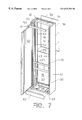
- FIG. 7 is a partially exploded perspective view of a cabinet including an equipment mounting rack according to an embodiment of the invention.
- FIG. 8 is a perspective view similar to FIG. 7 showing the assembled cabinet enclosing the equipment mounting rack in a shut condition.
- An equipment mounting rack 10 is composed of a seismically sound skeleton structure 12 having spaced vertical uprights 13 and 14 supplemented by distinct spaced equipment mounting structures 16 and 17 attached to the skeleton structure and extending along the vertical uprights.
- These equipment mounting structures 16 and 17 in effect constitute side wall structures of a mounting rack interior space 18 in lateral extension of the vertical uprights, such as seen in FIGS. 1 and 2, and include means, such as seen at 43 , for mounting equipment 20 and 21 , such as seen in FIGS. 2 and 5 to 7 .
- FIGS. 2 and 7 show a mounting board 20 attached to the opposite mounting structures 16 and 17 .
- Squares 21 in that mounting board either represent apertures for receiving equipment or symbolize equipment that may be mounted on the board 20 and thereby indirectly on the structures 16 and 17 in the rack interior 18 .
- such or other equipment may be mounted on the structures 16 and 17 directly, as may various fiber optics or other lines, cables, wiring, etc.
- the rack structure according to the invention is of wide utility, including facilities for mounting electrical and/or electronic equipment, facilities for mounting gas supply or transmission equipment, and facilities for mounting liquid fuel supply or transmission systems, or facilities for mounting fire-fighting equipment, hospital equipment and supplies, food and drink survival rations, and other articles, commodities and supplies needed for endurance of heavy earthquakes and other disasters, to name but a few examples where seismic stability and endurance are essential, especially in seismically active areas of the world.
- the spaced equipment mounting structures 16 and 17 may be spaced from vertical uprights 13 and 14 , or may be attached to such spaced vertical uprights.
- the vertical uprights 13 and 14 have elongate partial enclosures 23 extending along these vertical uprights, such as shown in FIG. 2 on an enlarged scale for the vertical upright 13 of the seismically sound skeleton structure 12 .
- the spaced equipment mounting structures 16 and 17 may be attached to these elongate partial enclosures, such as shown at 24 in FIG. 1, indicating fasteners 25 .
- the partial enclosure 23 adds strength to the upright structure and avoids damage to cables and wiring, as more fully disclosed below.
- Such partial enclosures may also be provided about other seismically sound structures.
- each of the vertical frame members of the equipment rack shown in U.S. Pat. No. 5,004,107, by coinventor Richard W. Sevier and by James J. Keenan, issued Apr. 2, 1991 to assignee Hendry Mechanical Works may be equipped with such a partial enclosure.
- the spaced vertical uprights 13 and 14 and the spaced equipment mounting structures 16 and 17 jointly constitute side wall structures of the mounting rack interior space 18 . This is so, even if these mounting structures have large apertures 26 , since an apertured wall is a wall nonetheless. These lateral apertures 26 permit fiber optics or other lines or cables or wiring to be conveniently run, and to be recurringly mounted or tied, such as at webs 27 . For this reason or otherwise, the equipment mounting structures 16 and 17 may be webbed.
- the seismically sound skeleton structure 12 includes cross piece structures 30 and 31 bracing the spaced vertical uprights 13 and 14 and the spaced equipment mounting structures 16 and 17 .
- the lower cross piece structure may be a base structure 30 included in the seismically sound skeleton structure 12 and carrying the spaced vertical uprights 13 and 14 and the spaced equipment mounting structures 16 and 17 .
- An excellent example of a seismically sound base structure is disclosed in the above mentioned U.S. Pat. No. 5,004,107, which is herewith incorporated by reference herein.
- a bracing member 29 in FIGS. 1 and 2 is indicative of the intimate interconnection of the components of the seismically sound skeleton structure 12 . Welding may be used extensively to brace the whole structure into one piece, so to speak.
- These and other base structures in effect may have extensions 32 and 33 at the spaced vertical uprights 13 and 14 , extending under the spaced equipment mounting structures 16 and 17 , such as seen in FIGS. 1 and 7.
- the seismically sound skeleton structure 12 includes cross piece structure 31 at tops of the spaced vertical uprights 13 and 14 , opposite to the base structure 30 .
- Such cross piece structure 31 preferably has transverse extensions 35 and 36 at spaced vertical uprights 13 and 14 , extending over the tops of the equipment mounting structures 16 and 17 .
- the upper exploded view in FIG. 1 shows an example of the cross piece extension 36 composed of a channel-shaped member 37 complemented by different angle members 38 and 39 , welded or braced into one piece.
- a strut plate 40 extends at an angle 41 , such as at 45 degrees to the vertical upright 13 and to the cross brace 31 .
- welding may be used to rigidify the skeleton structure with the strut 40 and with its counterpart in the other corner at 36 .
- bracing techniques are just some examples for providing the seismically sound structure within the scope of the invention herein disclosed.
- the spaced equipment mounting structures 16 and 17 have elongate mounting hole arrays 43 and 44 extending in parallel to the spaced vertical uprights 13 and 14 , respectively.
- Equipment, parts or components may be mounted directly onto these arrays, or indirectly, such as shown at 20 and 21 in FIGS. 2 and 7 by way of example.
- a related embodiment of the invention provides an equipment mounting rack 10 composed of seismically sound skeleton structure 12 having spaced vertical uprights 13 and 14 supplemented by distinct spaced equipment mounting structures 16 and 17 having elongate first sections 46 extending along these spaced vertical uprights, and elongate second sections 47 , seen particularly well in FIG. 6, extending along first sections 46 and constituting side wall structures of mounting rack interior space 18 .
- Elongate first sections 46 of the two mounting structures 16 and 17 may be attached to vertical uprights 13 and 14 , or to their above mentioned elongate partial enclosures 23 extending along such vertical uprights.
- the spaced vertical uprights 13 and 14 and the spaced equipment mounting structures 16 and 17 , and particularly, their elongate second sections 47 , may jointly constitute side wall structures of the mounting rack interior space 18 .
- the spaced equipment mounting structures 16 and 17 have elongate third sections 48 extending along second sections 47 . These elongate third sections 48 preferably are spaced from and extend substantially parallel to the first sections 46 .
- each equipment mounting structure has a rigidifying frame structure 46 - 50 - 48 - 51 thereabout, or about its second or main section 47 .
- the frame member or end plates 50 and 51 preferably are attached to or are one with that main section 47 .
- the distinct mounting structures 16 and 17 preferably are braced with or are at least connected to seismically sound skeleton structure, such as symbolically illustrated by a fastener 52 in FIG. 5 for one of the end plates.
- such distinct mounting structures 16 and 17 preferably are braced or are at least connected to seismically sound skeleton structure 12 on three sides each, such as at 46 - 23 - 13 or 14 , 50 - 32 or 33 and 51 - 35 or 36 .
- the elongate mounting hole arrays 43 and 44 of the spaced equipment mounting structures preferably extend along or at least are at the elongate third sections 48 . As seen best in FIGS. 5 and 6, the elongate mounting hole arrays 43 and 44 preferably are inwardly offset relative to the elongate third sections 48 .
- FIGS. 7 and 8 A special version of the equipment mounting rack according to a further embodiment of the invention is shown in FIGS. 7 and 8 by way of example.
- Such special version is composed of the seismically sound skeleton structure 12 having spaced vertical uprights 13 and 14 , spaced equipment mounting structures 16 and 17 attached to that skeleton structure, such as in any of the above mentioned manners, including intervening partial enclosure 23 , and extending along vertical uprights 13 and 14 , and cabinet walls 53 , 54 , 55 , 56 , etc., attached to skeleton structure 12 .
- the equipment mounting structures 16 and 17 constitute inside the cabinet walls 53 and 54 side wall structures of the mounting rack interior space 18 .
- the equipment mounting structures 16 and 17 and even the uprights 13 are 14 are inside walls, so to speak, and the cabinet walls 53 , 54 are outside walls.
- the equipment mounting structures 16 and 17 constitute side wall structures of the mounting rack interior space 18 inside the cabinet walls 53 and 54 , such as seen in FIG. 7 .
- the seismically sound skeleton structure 12 includes a base structure 30 , carrying the spaced vertical uprights 13 and 14 and having extensions 32 and 33 at the spaced vertical uprights extending under the spaced equipment mounting structures 16 and 17 .
- Cabinet walls 53 , 54 and 55 may be attached to such base structure 30 , 32 and 33 .
- the seismically sound skeleton structure 12 shown in FIGS. 7 and 8 also includes a cross piece structure 31 at tops of the spaced vertical uprights 13 and 14 opposite said base structure 30 , and such cross piece structure again has extensions 35 and 36 at the spaced vertical uprights 13 and 14 extending over the spaced equipment mounting structures 16 and 17 .
- Cabinet walls 53 , 54 and 56 may be attached to such top structure 31 , 35 , 36 .
- the equipment mounting rack preferably has a bottom opening 58 through which fiber optics or other lines or cables can be run, such as to and from a so-called computer floor or other supporting structure, or simply from the floor itself.
- a so-called computer floor or other supporting structure or simply from the floor itself.
- Particularly suitable rigid supporting structures are shown and described in U.S. Pat. No. 5,363,613, by coinventor Richard W. Sevier, issued Nov. 15, 1994 to assignee Hendry Mechanical Works.
- the equipment mounting rack also may have a top opening 59 through which fiber optics or other lines or cables can be run. In fact, such lines or cables may be run to and from openings 58 and 59 through the entire rack or cabinet.
- the cabinet shown in FIGS. 7 and 8 may be completed by a hinged door structure 60 , with top and bottom plates 61 and 62 being attached to the bottom and top structures 30 and 31 .
- FIGS. 2 and 7 show a spacer 64 between the rear of the upright 13 or upright enclosure 23 and the cabinet walls or panels 55 and 56 .
- a similar spacer may be attached to the other upright 14 or to its upright enclosure which corresponds to upright enclosure 23 .
- the cabinet walls or panels 55 and 56 may be attached to such spacers 64 on each back side of the vertical uprights 13 and 14 .
- a simple form of spacer is a rail with a C-shaped cross-section as seen in FIG. 2 .
- One leg of that C-shaped cross-section is visible at 64 in FIG. 7 .
- another equipment mounting structure similar to the equipment mounting structure 16 may be provided instead between the rear of the vertical upright 13 and the rear panels 55 and 56 .
- the vertical upright structure 13 may be provided between two equipment mounting structures of the type shown at 16 .
- the vertical upright structure 14 may be provided between two equipment mounting structures of the type shown at 17 thereby almost doubling the interior rack volume 18 and the equipment mounting capacity.
- an equipment mounting rack may have a seismically sound skeleton structure having spaced vertical uprights 13 and 14 , and elongate partial enclosures 23 extending along such vertical uprights, with each of these elongate partial enclosures having a main section 70 extending in parallel to a main section 71 of the corresponding vertical upright 13 , a first lateral section 72 extending from that main section 70 in spaced relationship to a first side 73 of that vertical upright and having a first extension 74 engaging that first side 73 of that vertical upright, and an opposite second lateral section 75 extending from the main section 70 in spaced relationship to an opposite second side 76 of that vertical upright and having a second extension 77 engaging that second side 76 of that vertical upright.
- the elongate upright partial enclosure 23 has a substantially C-shaped cross-section which has the vertical upright 13 between inwardly turned ends 74 and 77 of that C-shaped cross-section.
- Spacings 78 and 79 are important to seismic stability, strength and utility of the overall vertical upright structures 13 and 14 .
- fasteners such as fasteners 25 and 65 for equipment mounting structure 16 , for a spacer 64 or for another equipment mounting structure instead thereof, extend into spaces 78 and 79 , instead of through a wall of the seismically sound structure 12 , such as the wall 73 or 76 of the upright 13 .
- This not only avoids a weakening of the seismically sound structure by penetration of the uprights 13 and 14 with mounting holes and fasteners, but also precludes inside ends of such fasteners from penetrating into any space within uprights 13 and 14 .
- FIG. 3 shows a version wherein a mounting plate is attached to the partial upright enclosure 23 by a fastener 25 , and wherein an equipment mounting board, such as the above mentioned mounting board 20 , is attached to such mounting plate by another fastener 63 . In that case, neither fastener penetrates any wall 76 etc. of the upright 13 . The same applies when equipment.is directly attached to the mounting plate 22 , or even to the partial enclosure 23 .
- the main sections 70 and 71 of the partial enclosure 23 and upright 71 may also be spaced from each other, to provide a spacing around the upright core from extension 74 to extension 77 of that partial enclosure 23 .
- an equipment mounting rack that comprises a seismically sound skeleton structure having spaced vertical uprights 13 and 14 and a cross piece structure 31 attached to and extending between such vertical uprights, includes a strut plate 40 extending at an angle 41 between each of these vertical uprights and that cross piece structure 31 .
- such strut plate extends inside of each of the vertical uprights 13 and 14 and inside of the cross piece structured.
- the cross piece structure 31 forms a corner at each of the vertical uprights, such as seen in FIG. 4 for one of the vertical uprights.
- the strut plate 40 extends between that vertical upright and the cross piece structure inside of that vertical upright and inside that cross piece structure in spaced relationship to that corner at an angle 41 from a distance from that corner at that vertical upright to a distance from that corner at the cross piece structure.
- Elongate partial enclosures 23 may extend along the vertical uprights 13 and 14 , such as disclosed above with the aid of FIGS. 2 and 3.
- Distinct spaced equipment mounting structures 16 and 17 may again be attached to the skeleton structure 12 and extend along vertical uprights 13 and 14 and may, for instance, constitute side wall structures of a mounting rack interior space 18 .
Abstract
Description
Claims (26)
Priority Applications (3)
| Application Number | Priority Date | Filing Date | Title |
|---|---|---|---|
| US09/103,347 US6527351B1 (en) | 1998-06-23 | 1998-06-23 | Equipment mounting racks and cabinets |
| US09/688,103 US6561602B1 (en) | 1998-06-23 | 2000-10-13 | Equipment mounting racks and cabinets |
| US09/844,541 US6517174B2 (en) | 1998-06-23 | 2001-04-27 | Equipment mounting racks and cabinets |
Applications Claiming Priority (1)
| Application Number | Priority Date | Filing Date | Title |
|---|---|---|---|
| US09/103,347 US6527351B1 (en) | 1998-06-23 | 1998-06-23 | Equipment mounting racks and cabinets |
Related Child Applications (2)
| Application Number | Title | Priority Date | Filing Date |
|---|---|---|---|
| US09/688,103 Division US6561602B1 (en) | 1998-06-23 | 2000-10-13 | Equipment mounting racks and cabinets |
| US09/844,541 Division US6517174B2 (en) | 1998-06-23 | 2001-04-27 | Equipment mounting racks and cabinets |
Publications (1)
| Publication Number | Publication Date |
|---|---|
| US6527351B1 true US6527351B1 (en) | 2003-03-04 |
Family
ID=22294694
Family Applications (2)
| Application Number | Title | Priority Date | Filing Date |
|---|---|---|---|
| US09/103,347 Expired - Lifetime US6527351B1 (en) | 1998-06-23 | 1998-06-23 | Equipment mounting racks and cabinets |
| US09/844,541 Expired - Lifetime US6517174B2 (en) | 1998-06-23 | 2001-04-27 | Equipment mounting racks and cabinets |
Family Applications After (1)
| Application Number | Title | Priority Date | Filing Date |
|---|---|---|---|
| US09/844,541 Expired - Lifetime US6517174B2 (en) | 1998-06-23 | 2001-04-27 | Equipment mounting racks and cabinets |
Country Status (1)
| Country | Link |
|---|---|
| US (2) | US6527351B1 (en) |
Cited By (27)
| Publication number | Priority date | Publication date | Assignee | Title |
|---|---|---|---|---|
| US6695149B1 (en) * | 2002-08-09 | 2004-02-24 | Emc Corporation | Techniques for fastening a panel to an electronic cabinet frame |
| US20060043031A1 (en) * | 2004-08-26 | 2006-03-02 | Cooper Technologies Company | Electronic equipment rack |
| US20060081545A1 (en) * | 2004-10-15 | 2006-04-20 | Rasmussen Neil | Blanking panel for equipment rack or enclosure |
| US7090315B1 (en) * | 1998-12-30 | 2006-08-15 | Apw Electronics Limited | Electrical cabinet and a frame therefor |
| US20060243680A1 (en) * | 2005-04-28 | 2006-11-02 | Levesque Stewart A | Seismically sound rack system |
| US20070095774A1 (en) * | 2005-10-28 | 2007-05-03 | International Business Machines Corporation | Integrated frame and central electronic complex structure |
| US20080085638A1 (en) * | 2006-10-06 | 2008-04-10 | Baxter Robert C | Interconnect tower and relay rack assembly |
| USD630173S1 (en) | 2009-04-20 | 2011-01-04 | Chatsworth Products, Inc. | Cover for electronic equipment cabinet |
| USD632660S1 (en) | 2009-04-20 | 2011-02-15 | Chatsworth Products, Inc. | Cover for electronic equipment cabinet |
| USD651570S1 (en) * | 2010-01-16 | 2012-01-03 | Chatsworth Products, Inc. | Raceway for cable management |
| USD653623S1 (en) * | 2010-01-16 | 2012-02-07 | Chatsworth Products, Inc. | Raceway for cable management |
| US8424691B2 (en) | 2008-05-19 | 2013-04-23 | Chatsworth Products, Inc. | Seismically hardened two-post electronic equipment rack |
| USD684128S1 (en) | 2012-02-10 | 2013-06-11 | Chatsworth Products, Inc. | Containment aisle door |
| CN103208752A (en) * | 2011-05-20 | 2013-07-17 | 中国广东核电集团有限公司 | Aseismic structure for commutation device of emergency power system of nuclear power station |
| US8787023B2 (en) | 2010-09-10 | 2014-07-22 | Chatsworth Products, Inc. | Rail mounting clamp for electronic equipment enclosure |
| US8901438B2 (en) | 2010-09-10 | 2014-12-02 | Chatsworth Products, Inc. | Electronic equipment cabinet structure |
| US9055677B2 (en) | 2010-09-10 | 2015-06-09 | Chatsworth Products, Inc. | Cable pass-through panel for electronic equipment enclosure |
| US9206594B1 (en) | 2014-09-04 | 2015-12-08 | Columbia Insurance Company | Hanger with locator tooth |
| US9549487B2 (en) | 2013-12-17 | 2017-01-17 | Chatsworth Products, Inc. | Electronic equipment enclosure |
| US9560777B2 (en) | 2010-11-08 | 2017-01-31 | Chatsworth Products, Inc. | Door closer mechanism for hot/cold aisle air containment room |
| US9572286B2 (en) | 2013-01-11 | 2017-02-14 | Chatsworth Products, Inc. | Modular thermal isolation barrier for data processing equipment structure |
| US10271452B2 (en) | 2016-07-26 | 2019-04-23 | Chatsworth Products, Inc. | Features for cable managers and other electronic equipment structures |
| US11246231B2 (en) | 2012-02-10 | 2022-02-08 | Chatsworth Products, Inc. | Door closer mechanism for hot/cold aisle air containment room |
| US11622458B1 (en) | 2020-12-15 | 2023-04-04 | Chatsworth Products, Inc. | Brush port assembly and method for installing same |
| US11678458B1 (en) | 2020-12-15 | 2023-06-13 | Chatsworth Products, Inc. | Slidable mounting hardware for electronic equipment enclosure and method for installing same |
| US11818862B1 (en) | 2020-12-15 | 2023-11-14 | Chatsworth Products, Inc. | Frame structure for electronic equipment enclosure |
| US11920392B1 (en) | 2021-02-02 | 2024-03-05 | Chatsworth Products, Inc. | Electrical bonding door hinges |
Families Citing this family (6)
| Publication number | Priority date | Publication date | Assignee | Title |
|---|---|---|---|---|
| US20070163978A1 (en) * | 2006-01-18 | 2007-07-19 | Fa Hung | Collapsible storage rack |
| US20070175836A1 (en) * | 2006-01-27 | 2007-08-02 | Gerhard Bumeder | Frame structure |
| US8290331B2 (en) * | 2008-10-24 | 2012-10-16 | Adc Telecommunications, Inc. | Spacer box and interbay cable management panel |
| US9383536B2 (en) | 2012-03-07 | 2016-07-05 | Commscope Technologies Llc | Spacer box extension kit and interbay cable management panel |
| US9226577B2 (en) * | 2012-07-26 | 2016-01-05 | Prosteel Security Products Inc. | Modular safe interior |
| CN111817150B (en) * | 2020-06-11 | 2022-07-26 | 阜阳腾冠电力科技有限公司 | Switch board convenient to maintenance and repair |
Citations (45)
| Publication number | Priority date | Publication date | Assignee | Title |
|---|---|---|---|---|
| US1516711A (en) | 1923-04-16 | 1924-11-25 | John P Christell | Porch-rail safety device |
| US1957362A (en) | 1932-07-29 | 1934-05-01 | George L Smith | Bricklayer's trestle or horse |
| US2058263A (en) | 1935-07-11 | 1936-10-20 | Western Electric Co | Cabinet |
| US2114155A (en) | 1935-12-09 | 1938-04-12 | Simplex Metal Housing Corp | Building construction |
| US2386019A (en) | 1943-01-28 | 1945-10-02 | Budd Edward G Mfg Co | Truss structure and parts thereof |
| US2875902A (en) | 1956-03-21 | 1959-03-03 | American Viscose Corp | Track extensions for beam racks |
| GB815777A (en) | 1958-02-11 | 1959-07-01 | Standard Telephones Cables Ltd | Improvements in or relating to mounting arrangements for electric equipment |
| US2950786A (en) | 1954-01-27 | 1960-08-30 | Markle Lafayette | Building system |
| US2959715A (en) | 1958-10-24 | 1960-11-08 | Leonchick Walter | Instrument rack assembly |
| US3160280A (en) | 1963-08-12 | 1964-12-08 | Gen Electric | Device for mounting apparatus |
| GB983471A (en) | 1963-07-03 | 1965-02-17 | Tensile Products Ltd | Improvements in or relating to plastic clad frames |
| US3192306A (en) * | 1962-09-26 | 1965-06-29 | Philco Corp | Cooling wall structure for electronic equipment cabinet |
| US3265419A (en) | 1963-12-30 | 1966-08-09 | Honeywell Inc | Cabinet structure |
| US3297383A (en) | 1965-04-29 | 1967-01-10 | Equipto Electronics Corp | Corner construction for a cabinet |
| US3420381A (en) | 1966-11-14 | 1969-01-07 | Gen Communications Products In | Apparatus for electrical components |
| US3537221A (en) | 1967-06-19 | 1970-11-03 | Leroy Helfman | Building structure with separate floor and ceiling joists |
| US3907445A (en) | 1975-01-06 | 1975-09-23 | United States Gypsum Co | Self-aligning joist hanger for structural steel framing |
| US3989398A (en) | 1975-01-06 | 1976-11-02 | United States Gypsum Company | Clip-on attachment members for structural steel joists |
| DE2609100A1 (en) * | 1976-03-05 | 1977-09-08 | Schaefer Gmbh Fritz | KIT FOR THE PRODUCTION OF SHELVES OF VARIABLE SIZES |
| US4141054A (en) | 1977-09-28 | 1979-02-20 | Westinghouse Electric Corp. | Seismic tolerant electrical unit substation |
| US4410294A (en) | 1981-05-07 | 1983-10-18 | Simpson Strong-Tie Company, Inc. | Variable pitch connector |
| US4422792A (en) | 1982-08-16 | 1983-12-27 | Simpson Strong-Tie Company, Inc. | Gusset metal ledger hanger |
| US4497411A (en) | 1982-04-19 | 1985-02-05 | Northern Telecom Limited | Distributing frame for telecommunications systems |
| US4553674A (en) | 1981-01-30 | 1985-11-19 | Hitachi, Ltd. | Casing construction for electronic equipment |
| US4572695A (en) | 1984-08-20 | 1986-02-25 | Simpson Strong-Tie Company, Inc. | Six finger wood jointing connector |
| US4594017A (en) | 1985-06-17 | 1986-06-10 | Altech Industries, Inc. | Joist hanger and blank therefor |
| US4641987A (en) | 1985-06-28 | 1987-02-10 | Schlegel Gary R | Clip for suspended ceiling gridwork |
| US4662524A (en) | 1983-01-31 | 1987-05-05 | Hill-Rom Company, Inc. | Medical service column and mounting bracket |
| US4690286A (en) | 1985-09-19 | 1987-09-01 | Bicc Public Limited Company | Enclosure for housing circuit boards |
| US4715502A (en) | 1986-02-20 | 1987-12-29 | Newton Instrument Company | Telephone equipment rack |
| US4732281A (en) | 1986-03-31 | 1988-03-22 | The Babcock & Wilcox Company | Mounting bracket assembly for electronic instrument mounting, heat dissipation and environmental protection |
| US4899892A (en) | 1988-03-08 | 1990-02-13 | Northern Telecom Limited | Earthquake-resistant electronic equipment frame |
| US4991061A (en) | 1989-09-22 | 1991-02-05 | Westinghouse Electric Corp. | Adjustable starter baseplate assembly |
| US5004107A (en) | 1989-05-05 | 1991-04-02 | Hendry Mechanical Works | Earthquake braced racks |
| USD326200S (en) | 1989-08-11 | 1992-05-19 | International Business Machines Corporation | Rack for electronic equipment |
| GB2254962A (en) | 1991-04-04 | 1992-10-21 | Loh Kg Rittal Werk | Modular housing or rack assembly |
| US5165770A (en) * | 1991-03-29 | 1992-11-24 | Richard Hahn | Electronic equipment modular cabinet system |
| US5214572A (en) | 1991-08-21 | 1993-05-25 | International Business Machines Corporation | One-piece electronic cage |
| US5284254A (en) | 1992-06-24 | 1994-02-08 | B-Line Systems, Inc. | Rack for electrical equipment |
| US5323916A (en) | 1992-12-23 | 1994-06-28 | Newton Instrument Company, Inc. | Unequal flange-type telephone equipment rack adapted for universal application |
| US5363613A (en) | 1992-03-12 | 1994-11-15 | Hendry Mechanical Works | Rigid supporting structures |
| US5372262A (en) | 1991-06-28 | 1994-12-13 | Digital Equipment Corporation | Frame assembly for rack-mountable equipment |
| US5441337A (en) * | 1993-10-06 | 1995-08-15 | Schroff Gmbh | Component cabinet |
| US5639150A (en) * | 1995-09-22 | 1997-06-17 | Amco Engineering Co. | Electronic component enclosure and method |
| US5664380A (en) * | 1995-07-12 | 1997-09-09 | Hsueh; Jen Shiung | Partition frame structure |
Family Cites Families (8)
| Publication number | Priority date | Publication date | Assignee | Title |
|---|---|---|---|---|
| FR2299544A1 (en) * | 1975-01-31 | 1976-08-27 | Vasseur & Cie Ets | Storage framework for use with pallets - has vertical, longitudinal and transverse members linked by adjustable brackets |
| US4158998A (en) * | 1976-05-12 | 1979-06-26 | The Mead Corporation | Shelf support structure |
| US4453472A (en) | 1982-02-22 | 1984-06-12 | M. E. Canfield Company | Rack structure |
| US5743413A (en) | 1995-04-06 | 1998-04-28 | Noll; Ronald C. | Expandable shelf kit/log holder |
| US5566836A (en) | 1995-06-01 | 1996-10-22 | Homaco, Inc. | Telecommunication relay rack |
| FR2736138B1 (en) | 1995-06-27 | 1997-08-22 | Mavil | DEVICE FOR FIXING HORIZONTAL CONSOLES ON A VERTICAL RACK POST |
| US5979672A (en) | 1996-04-10 | 1999-11-09 | Telcordia Technologies, Inc. | Earthquake resistant enclosure for electronic equipment |
| US5983590A (en) | 1997-05-29 | 1999-11-16 | The Crown Division | Earthquake resistant equipment rack |
-
1998
- 1998-06-23 US US09/103,347 patent/US6527351B1/en not_active Expired - Lifetime
-
2001
- 2001-04-27 US US09/844,541 patent/US6517174B2/en not_active Expired - Lifetime
Patent Citations (45)
| Publication number | Priority date | Publication date | Assignee | Title |
|---|---|---|---|---|
| US1516711A (en) | 1923-04-16 | 1924-11-25 | John P Christell | Porch-rail safety device |
| US1957362A (en) | 1932-07-29 | 1934-05-01 | George L Smith | Bricklayer's trestle or horse |
| US2058263A (en) | 1935-07-11 | 1936-10-20 | Western Electric Co | Cabinet |
| US2114155A (en) | 1935-12-09 | 1938-04-12 | Simplex Metal Housing Corp | Building construction |
| US2386019A (en) | 1943-01-28 | 1945-10-02 | Budd Edward G Mfg Co | Truss structure and parts thereof |
| US2950786A (en) | 1954-01-27 | 1960-08-30 | Markle Lafayette | Building system |
| US2875902A (en) | 1956-03-21 | 1959-03-03 | American Viscose Corp | Track extensions for beam racks |
| GB815777A (en) | 1958-02-11 | 1959-07-01 | Standard Telephones Cables Ltd | Improvements in or relating to mounting arrangements for electric equipment |
| US2959715A (en) | 1958-10-24 | 1960-11-08 | Leonchick Walter | Instrument rack assembly |
| US3192306A (en) * | 1962-09-26 | 1965-06-29 | Philco Corp | Cooling wall structure for electronic equipment cabinet |
| GB983471A (en) | 1963-07-03 | 1965-02-17 | Tensile Products Ltd | Improvements in or relating to plastic clad frames |
| US3160280A (en) | 1963-08-12 | 1964-12-08 | Gen Electric | Device for mounting apparatus |
| US3265419A (en) | 1963-12-30 | 1966-08-09 | Honeywell Inc | Cabinet structure |
| US3297383A (en) | 1965-04-29 | 1967-01-10 | Equipto Electronics Corp | Corner construction for a cabinet |
| US3420381A (en) | 1966-11-14 | 1969-01-07 | Gen Communications Products In | Apparatus for electrical components |
| US3537221A (en) | 1967-06-19 | 1970-11-03 | Leroy Helfman | Building structure with separate floor and ceiling joists |
| US3907445A (en) | 1975-01-06 | 1975-09-23 | United States Gypsum Co | Self-aligning joist hanger for structural steel framing |
| US3989398A (en) | 1975-01-06 | 1976-11-02 | United States Gypsum Company | Clip-on attachment members for structural steel joists |
| DE2609100A1 (en) * | 1976-03-05 | 1977-09-08 | Schaefer Gmbh Fritz | KIT FOR THE PRODUCTION OF SHELVES OF VARIABLE SIZES |
| US4141054A (en) | 1977-09-28 | 1979-02-20 | Westinghouse Electric Corp. | Seismic tolerant electrical unit substation |
| US4553674A (en) | 1981-01-30 | 1985-11-19 | Hitachi, Ltd. | Casing construction for electronic equipment |
| US4410294A (en) | 1981-05-07 | 1983-10-18 | Simpson Strong-Tie Company, Inc. | Variable pitch connector |
| US4497411A (en) | 1982-04-19 | 1985-02-05 | Northern Telecom Limited | Distributing frame for telecommunications systems |
| US4422792A (en) | 1982-08-16 | 1983-12-27 | Simpson Strong-Tie Company, Inc. | Gusset metal ledger hanger |
| US4662524A (en) | 1983-01-31 | 1987-05-05 | Hill-Rom Company, Inc. | Medical service column and mounting bracket |
| US4572695A (en) | 1984-08-20 | 1986-02-25 | Simpson Strong-Tie Company, Inc. | Six finger wood jointing connector |
| US4594017A (en) | 1985-06-17 | 1986-06-10 | Altech Industries, Inc. | Joist hanger and blank therefor |
| US4641987A (en) | 1985-06-28 | 1987-02-10 | Schlegel Gary R | Clip for suspended ceiling gridwork |
| US4690286A (en) | 1985-09-19 | 1987-09-01 | Bicc Public Limited Company | Enclosure for housing circuit boards |
| US4715502A (en) | 1986-02-20 | 1987-12-29 | Newton Instrument Company | Telephone equipment rack |
| US4732281A (en) | 1986-03-31 | 1988-03-22 | The Babcock & Wilcox Company | Mounting bracket assembly for electronic instrument mounting, heat dissipation and environmental protection |
| US4899892A (en) | 1988-03-08 | 1990-02-13 | Northern Telecom Limited | Earthquake-resistant electronic equipment frame |
| US5004107A (en) | 1989-05-05 | 1991-04-02 | Hendry Mechanical Works | Earthquake braced racks |
| USD326200S (en) | 1989-08-11 | 1992-05-19 | International Business Machines Corporation | Rack for electronic equipment |
| US4991061A (en) | 1989-09-22 | 1991-02-05 | Westinghouse Electric Corp. | Adjustable starter baseplate assembly |
| US5165770A (en) * | 1991-03-29 | 1992-11-24 | Richard Hahn | Electronic equipment modular cabinet system |
| GB2254962A (en) | 1991-04-04 | 1992-10-21 | Loh Kg Rittal Werk | Modular housing or rack assembly |
| US5372262A (en) | 1991-06-28 | 1994-12-13 | Digital Equipment Corporation | Frame assembly for rack-mountable equipment |
| US5214572A (en) | 1991-08-21 | 1993-05-25 | International Business Machines Corporation | One-piece electronic cage |
| US5363613A (en) | 1992-03-12 | 1994-11-15 | Hendry Mechanical Works | Rigid supporting structures |
| US5284254A (en) | 1992-06-24 | 1994-02-08 | B-Line Systems, Inc. | Rack for electrical equipment |
| US5323916A (en) | 1992-12-23 | 1994-06-28 | Newton Instrument Company, Inc. | Unequal flange-type telephone equipment rack adapted for universal application |
| US5441337A (en) * | 1993-10-06 | 1995-08-15 | Schroff Gmbh | Component cabinet |
| US5664380A (en) * | 1995-07-12 | 1997-09-09 | Hsueh; Jen Shiung | Partition frame structure |
| US5639150A (en) * | 1995-09-22 | 1997-06-17 | Amco Engineering Co. | Electronic component enclosure and method |
Non-Patent Citations (3)
| Title |
|---|
| David E. Kosanda, Design and Testing of an Earth-quake-Resistant Electronic Equipment Rack, 1987 International Electronics Packaging Conference. |
| Lincoln Electric, "How Welding Simplifies the Design of Brackets," Product Engineering, Nov. 1948. |
| Seismic Simulation Test Program on Two LTS-1565 Equipment Racks, for Rockwell International, by Wyle Laboratories, Feb. 11, 1986. |
Cited By (65)
| Publication number | Priority date | Publication date | Assignee | Title |
|---|---|---|---|---|
| US7090315B1 (en) * | 1998-12-30 | 2006-08-15 | Apw Electronics Limited | Electrical cabinet and a frame therefor |
| US6695149B1 (en) * | 2002-08-09 | 2004-02-24 | Emc Corporation | Techniques for fastening a panel to an electronic cabinet frame |
| US20060043031A1 (en) * | 2004-08-26 | 2006-03-02 | Cooper Technologies Company | Electronic equipment rack |
| US8052231B2 (en) | 2004-10-15 | 2011-11-08 | American Power Conversion Corporation | Blanking panel for equipment rack or enclosure |
| US7506768B2 (en) * | 2004-10-15 | 2009-03-24 | American Power Conversion Corporation | Blanking panel for equipment rack or enclosure |
| US20060081545A1 (en) * | 2004-10-15 | 2006-04-20 | Rasmussen Neil | Blanking panel for equipment rack or enclosure |
| US20090178991A1 (en) * | 2004-10-15 | 2009-07-16 | American Power Conversion Corporation | Blanking panel for equipment rack or enclosure |
| US7874433B2 (en) | 2005-04-28 | 2011-01-25 | Ortronics, Inc. | Seismically sound rack system |
| US20060243680A1 (en) * | 2005-04-28 | 2006-11-02 | Levesque Stewart A | Seismically sound rack system |
| US20070095774A1 (en) * | 2005-10-28 | 2007-05-03 | International Business Machines Corporation | Integrated frame and central electronic complex structure |
| US8079481B2 (en) * | 2005-10-28 | 2011-12-20 | International Business Machines Corporation | Integrated frame and central electronic complex structure |
| US20080085638A1 (en) * | 2006-10-06 | 2008-04-10 | Baxter Robert C | Interconnect tower and relay rack assembly |
| US8424691B2 (en) | 2008-05-19 | 2013-04-23 | Chatsworth Products, Inc. | Seismically hardened two-post electronic equipment rack |
| USD630173S1 (en) | 2009-04-20 | 2011-01-04 | Chatsworth Products, Inc. | Cover for electronic equipment cabinet |
| USD632660S1 (en) | 2009-04-20 | 2011-02-15 | Chatsworth Products, Inc. | Cover for electronic equipment cabinet |
| USD651570S1 (en) * | 2010-01-16 | 2012-01-03 | Chatsworth Products, Inc. | Raceway for cable management |
| USD653623S1 (en) * | 2010-01-16 | 2012-02-07 | Chatsworth Products, Inc. | Raceway for cable management |
| US9980400B2 (en) | 2010-09-10 | 2018-05-22 | Chatsworth Products, Inc. | Rail seal for electronic equipment enclosure |
| US10178784B2 (en) | 2010-09-10 | 2019-01-08 | Chatsworth Products, Inc. | Rail seal for electronic equipment enclosure |
| US8787023B2 (en) | 2010-09-10 | 2014-07-22 | Chatsworth Products, Inc. | Rail mounting clamp for electronic equipment enclosure |
| US8901438B2 (en) | 2010-09-10 | 2014-12-02 | Chatsworth Products, Inc. | Electronic equipment cabinet structure |
| US9055677B2 (en) | 2010-09-10 | 2015-06-09 | Chatsworth Products, Inc. | Cable pass-through panel for electronic equipment enclosure |
| US11792948B2 (en) | 2010-09-10 | 2023-10-17 | Chatsworth Products, Inc. | Cable pass-through panel for electronic equipment enclosure |
| US10653025B2 (en) | 2010-09-10 | 2020-05-12 | Chatsworth Products, Inc. | Cable pass-through panel for electronic equipment enclosure |
| US9408326B2 (en) | 2010-09-10 | 2016-08-02 | Chatsworth Products, Inc. | Electronic equipment cabinet structure |
| US11464123B2 (en) | 2010-09-10 | 2022-10-04 | Chatsworth Products, Inc. | Method of adapting an electronic equipment enclosure for cable management |
| US10237994B2 (en) | 2010-09-10 | 2019-03-19 | Chatsworth Products, Inc. | Vertical mounting rail with cable management features |
| US10588227B2 (en) | 2010-09-10 | 2020-03-10 | Chatsworth Products, Inc. | Vertical mounting rail with cable management features |
| US9642270B2 (en) | 2010-09-10 | 2017-05-02 | Chatsworth Products, Inc. | Rail seal for electronic equipment enclosure |
| US9781852B2 (en) | 2010-09-10 | 2017-10-03 | Chatsworth Products, Inc. | Cable pass-through panel for electronic equipment enclosure |
| US11039543B2 (en) | 2010-09-10 | 2021-06-15 | Chatsworth Products, Inc. | Vertical mounting rail with cable management features |
| US9814159B2 (en) | 2010-09-10 | 2017-11-07 | Chatsworth Products, Inc. | Rail seal for electronic equipment enclosure |
| US9560777B2 (en) | 2010-11-08 | 2017-01-31 | Chatsworth Products, Inc. | Door closer mechanism for hot/cold aisle air containment room |
| US10362695B2 (en) | 2010-11-08 | 2019-07-23 | Chatsworth Products, Inc. | Door closer mechanism for hot/cold aisle air containment room |
| CN103208752B (en) * | 2011-05-20 | 2016-04-13 | 中国广核集团有限公司 | A kind of anti-seismic structure for nuclear power station emergency power supply system current converter |
| CN103208752A (en) * | 2011-05-20 | 2013-07-17 | 中国广东核电集团有限公司 | Aseismic structure for commutation device of emergency power system of nuclear power station |
| USD684128S1 (en) | 2012-02-10 | 2013-06-11 | Chatsworth Products, Inc. | Containment aisle door |
| US11246231B2 (en) | 2012-02-10 | 2022-02-08 | Chatsworth Products, Inc. | Door closer mechanism for hot/cold aisle air containment room |
| US10595442B2 (en) | 2013-01-11 | 2020-03-17 | Chatsworth Products, Inc. | Data processing equipment structure |
| US9572286B2 (en) | 2013-01-11 | 2017-02-14 | Chatsworth Products, Inc. | Modular thermal isolation barrier for data processing equipment structure |
| US10375861B2 (en) | 2013-01-11 | 2019-08-06 | Chatsworth Products, Inc. | Modular thermal isolation barrier for data processing equipment structure |
| US9795060B2 (en) | 2013-01-11 | 2017-10-17 | Chatsworth Products, Inc. | Modular thermal isolation barrier for data processing equipment structure |
| US11647610B2 (en) | 2013-01-11 | 2023-05-09 | Chatsworth Products, Inc. | Modular thermal isolation barrier for data processing equipment structure |
| US11083108B2 (en) | 2013-12-17 | 2021-08-03 | Chatsworth Products, Inc. | Electronic equipment enclosure |
| US9549487B2 (en) | 2013-12-17 | 2017-01-17 | Chatsworth Products, Inc. | Electronic equipment enclosure |
| US9206594B1 (en) | 2014-09-04 | 2015-12-08 | Columbia Insurance Company | Hanger with locator tooth |
| US11619328B2 (en) | 2016-07-26 | 2023-04-04 | Chatsworth Products, Inc. | Method of adapting electronic equipment structure for cable management |
| US11644125B2 (en) | 2016-07-26 | 2023-05-09 | Chatsworth Products, Inc. | Method of installing cable finger accessory in a cable manager |
| US11162615B2 (en) | 2016-07-26 | 2021-11-02 | Chatsworth Products, Inc. | Features for cable managers and other electronic equipment structures |
| US11493151B2 (en) | 2016-07-26 | 2022-11-08 | Chatsworth Products, Inc. | Features for cable managers and other electronic equipment structures |
| US11815197B2 (en) | 2016-07-26 | 2023-11-14 | Chatsworth Products, Inc. | Features for cable managers and other electronic equipment structures |
| US10477720B2 (en) | 2016-07-26 | 2019-11-12 | Chatsworth Products, Inc. | Features for cable managers and other electronic equipment structures |
| US10271452B2 (en) | 2016-07-26 | 2019-04-23 | Chatsworth Products, Inc. | Features for cable managers and other electronic equipment structures |
| US11644126B2 (en) | 2016-07-26 | 2023-05-09 | Chatsworth Products, Inc. | Method of installing half-spool accessory in a cable manager |
| US11071227B2 (en) | 2016-07-26 | 2021-07-20 | Chatsworth Products, Inc. | Accessory rod assembly for a cable manager |
| US11268636B2 (en) | 2016-07-26 | 2022-03-08 | Chatsworth Products, Inc. | Features for cable managers and other electronic equipment structures |
| US11678458B1 (en) | 2020-12-15 | 2023-06-13 | Chatsworth Products, Inc. | Slidable mounting hardware for electronic equipment enclosure and method for installing same |
| US11678456B1 (en) | 2020-12-15 | 2023-06-13 | Chatsworth Products, Inc. | Slidable mounting hardware for electronic equipment enclosure and method for installing same |
| US11627677B1 (en) | 2020-12-15 | 2023-04-11 | Chatsworth Products, Inc. | Brush port assembly and method for installing same |
| US11818862B1 (en) | 2020-12-15 | 2023-11-14 | Chatsworth Products, Inc. | Frame structure for electronic equipment enclosure |
| US11818861B1 (en) | 2020-12-15 | 2023-11-14 | Chatsworth Products, Inc. | Frame structure for electronic equipment enclosure |
| US11622458B1 (en) | 2020-12-15 | 2023-04-04 | Chatsworth Products, Inc. | Brush port assembly and method for installing same |
| US11818860B1 (en) | 2020-12-15 | 2023-11-14 | Chatsworth Products, Inc. | Frame structure for electronic equipment enclosure |
| US11903156B1 (en) | 2020-12-15 | 2024-02-13 | Chatsworth Products, Inc. | Brush port assembly and method for installing same |
| US11920392B1 (en) | 2021-02-02 | 2024-03-05 | Chatsworth Products, Inc. | Electrical bonding door hinges |
Also Published As
| Publication number | Publication date |
|---|---|
| US6517174B2 (en) | 2003-02-11 |
| US20010015598A1 (en) | 2001-08-23 |
Similar Documents
| Publication | Publication Date | Title |
|---|---|---|
| US6527351B1 (en) | Equipment mounting racks and cabinets | |
| US6561602B1 (en) | Equipment mounting racks and cabinets | |
| US6036290A (en) | Seismic subframe for electrical enclosure | |
| US20060043031A1 (en) | Electronic equipment rack | |
| US6293637B1 (en) | Earthquake-resistant electronic equipment frame | |
| US6067233A (en) | Mounting brace and cable management apparatus and method | |
| BG62115B1 (en) | Frame-type chassis for a distribution board | |
| US4173934A (en) | Shelving structure | |
| US6017104A (en) | Cabinet structure, having variable size, for electric and/or electronic equipments | |
| US4113331A (en) | Modular console enclosure with writing surface | |
| US4053245A (en) | Connector | |
| US4836481A (en) | Support for writing desks | |
| US3679067A (en) | Storage rack and bracket therefor | |
| KR101751651B1 (en) | Earthquake-Resistant Swichboard with Enclosure Applied Triaxis Corner Piece of Double and Symmetric Structure | |
| US2945596A (en) | Extendible rack structure for storage, embodying wing extensions | |
| JP3551398B2 (en) | Shelf equipment | |
| CN216930504U (en) | Novel antidetonation rack | |
| JP3653644B2 (en) | Shelf equipment | |
| JP2998064B2 (en) | Cabinet structure in a modular shelf | |
| CN212435077U (en) | Low-voltage switchgear convenient to dismouting | |
| CA1085777A (en) | Shelving structure | |
| JP2705279B2 (en) | Structure of frame for communication system | |
| JP3653643B2 (en) | Shelf equipment | |
| CN209982873U (en) | Expansion type cabinet | |
| JPS628781Y2 (en) |
Legal Events
| Date | Code | Title | Description |
|---|---|---|---|
| AS | Assignment |
Owner name: HENDRY MECHANICAL WORKS, CALIFORNIA Free format text: ASSIGNMENT OF ASSIGNORS INTEREST;ASSIGNORS:SEVIER, RICHARD W.;LOUWAGIE, DOMINIC J.;REEL/FRAME:009274/0456;SIGNING DATES FROM 19980612 TO 19980622 Owner name: ADC TELECOMMUNICATIONS, INC., MINNESOTA Free format text: ASSIGNMENT OF ASSIGNORS INTEREST;ASSIGNORS:SEVIER, RICHARD W.;LOUWAGIE, DOMINIC J.;REEL/FRAME:009274/0456;SIGNING DATES FROM 19980612 TO 19980622 |
|
| STCF | Information on status: patent grant |
Free format text: PATENTED CASE |
|
| AS | Assignment |
Owner name: TELECT, INC., WASHINGTON Free format text: ASSIGNMENT OF ASSIGNORS INTEREST;ASSIGNOR:HENDRY MECHANICAL WORKS;REEL/FRAME:015320/0386 Effective date: 20041025 |
|
| AS | Assignment |
Owner name: COMERICA BANK, CALIFORNIA Free format text: SECURITY AGREEMENT;ASSIGNOR:TELECT, INC.;REEL/FRAME:016263/0030 Effective date: 20050526 |
|
| FEPP | Fee payment procedure |
Free format text: PAT HOLDER NO LONGER CLAIMS SMALL ENTITY STATUS, ENTITY STATUS SET TO UNDISCOUNTED (ORIGINAL EVENT CODE: STOL); ENTITY STATUS OF PATENT OWNER: SMALL ENTITY |
|
| REFU | Refund |
Free format text: REFUND - SURCHARGE, PETITION TO ACCEPT PYMT AFTER EXP, UNINTENTIONAL (ORIGINAL EVENT CODE: R2551); ENTITY STATUS OF PATENT OWNER: SMALL ENTITY |
|
| FPAY | Fee payment |
Year of fee payment: 4 |
|
| FEPP | Fee payment procedure |
Free format text: PAT HOLDER CLAIMS SMALL ENTITY STATUS, ENTITY STATUS SET TO SMALL (ORIGINAL EVENT CODE: LTOS); ENTITY STATUS OF PATENT OWNER: SMALL ENTITY |
|
| FPAY | Fee payment |
Year of fee payment: 8 |
|
| FPAY | Fee payment |
Year of fee payment: 12 |
|
| AS | Assignment |
Owner name: ADC TELECOMMUNICATIONS, INC., MINNESOTA Free format text: ASSIGNMENT OF ASSIGNORS INTEREST;ASSIGNORS:SEVIER, RICHARD W.;LOUWAGIE, DOMINIC J.;SIGNING DATES FROM 19980612 TO 19980622;REEL/FRAME:036270/0389 |
|
| AS | Assignment |
Owner name: TYCO ELECTRONICS SERVICES GMBH, SWITZERLAND Free format text: ASSIGNMENT OF ASSIGNORS INTEREST;ASSIGNORS:ADC TELECOMMUNICATIONS, INC.;TE CONNECTIVITY SOLUTIONS GMBH;REEL/FRAME:036908/0443 Effective date: 20150825 |
|
| AS | Assignment |
Owner name: COMMSCOPE EMEA LIMITED, IRELAND Free format text: ASSIGNMENT OF ASSIGNORS INTEREST;ASSIGNOR:TYCO ELECTRONICS SERVICES GMBH;REEL/FRAME:036956/0001 Effective date: 20150828 |
|
| AS | Assignment |
Owner name: COMMSCOPE TECHNOLOGIES LLC, NORTH CAROLINA Free format text: ASSIGNMENT OF ASSIGNORS INTEREST;ASSIGNOR:COMMSCOPE EMEA LIMITED;REEL/FRAME:037012/0001 Effective date: 20150828 |
|
| AS | Assignment |
Owner name: JPMORGAN CHASE BANK, N.A., AS COLLATERAL AGENT, ILLINOIS Free format text: PATENT SECURITY AGREEMENT (TERM);ASSIGNOR:COMMSCOPE TECHNOLOGIES LLC;REEL/FRAME:037513/0709 Effective date: 20151220 Owner name: JPMORGAN CHASE BANK, N.A., AS COLLATERAL AGENT, ILLINOIS Free format text: PATENT SECURITY AGREEMENT (ABL);ASSIGNOR:COMMSCOPE TECHNOLOGIES LLC;REEL/FRAME:037514/0196 Effective date: 20151220 Owner name: JPMORGAN CHASE BANK, N.A., AS COLLATERAL AGENT, IL Free format text: PATENT SECURITY AGREEMENT (TERM);ASSIGNOR:COMMSCOPE TECHNOLOGIES LLC;REEL/FRAME:037513/0709 Effective date: 20151220 Owner name: JPMORGAN CHASE BANK, N.A., AS COLLATERAL AGENT, IL Free format text: PATENT SECURITY AGREEMENT (ABL);ASSIGNOR:COMMSCOPE TECHNOLOGIES LLC;REEL/FRAME:037514/0196 Effective date: 20151220 |
|
| AS | Assignment |
Owner name: ANDREW LLC, NORTH CAROLINA Free format text: RELEASE BY SECURED PARTY;ASSIGNOR:JPMORGAN CHASE BANK, N.A.;REEL/FRAME:048840/0001 Effective date: 20190404 Owner name: COMMSCOPE TECHNOLOGIES LLC, NORTH CAROLINA Free format text: RELEASE BY SECURED PARTY;ASSIGNOR:JPMORGAN CHASE BANK, N.A.;REEL/FRAME:048840/0001 Effective date: 20190404 Owner name: COMMSCOPE, INC. OF NORTH CAROLINA, NORTH CAROLINA Free format text: RELEASE BY SECURED PARTY;ASSIGNOR:JPMORGAN CHASE BANK, N.A.;REEL/FRAME:048840/0001 Effective date: 20190404 Owner name: ALLEN TELECOM LLC, ILLINOIS Free format text: RELEASE BY SECURED PARTY;ASSIGNOR:JPMORGAN CHASE BANK, N.A.;REEL/FRAME:048840/0001 Effective date: 20190404 Owner name: REDWOOD SYSTEMS, INC., NORTH CAROLINA Free format text: RELEASE BY SECURED PARTY;ASSIGNOR:JPMORGAN CHASE BANK, N.A.;REEL/FRAME:048840/0001 Effective date: 20190404 Owner name: ALLEN TELECOM LLC, ILLINOIS Free format text: RELEASE BY SECURED PARTY;ASSIGNOR:JPMORGAN CHASE BANK, N.A.;REEL/FRAME:049260/0001 Effective date: 20190404 Owner name: ANDREW LLC, NORTH CAROLINA Free format text: RELEASE BY SECURED PARTY;ASSIGNOR:JPMORGAN CHASE BANK, N.A.;REEL/FRAME:049260/0001 Effective date: 20190404 Owner name: COMMSCOPE TECHNOLOGIES LLC, NORTH CAROLINA Free format text: RELEASE BY SECURED PARTY;ASSIGNOR:JPMORGAN CHASE BANK, N.A.;REEL/FRAME:049260/0001 Effective date: 20190404 Owner name: REDWOOD SYSTEMS, INC., NORTH CAROLINA Free format text: RELEASE BY SECURED PARTY;ASSIGNOR:JPMORGAN CHASE BANK, N.A.;REEL/FRAME:049260/0001 Effective date: 20190404 Owner name: COMMSCOPE, INC. OF NORTH CAROLINA, NORTH CAROLINA Free format text: RELEASE BY SECURED PARTY;ASSIGNOR:JPMORGAN CHASE BANK, N.A.;REEL/FRAME:049260/0001 Effective date: 20190404 |