US6528131B1 - Insulated assembly incorporating a thermoplastic barrier member - Google Patents
Insulated assembly incorporating a thermoplastic barrier member Download PDFInfo
- Publication number
- US6528131B1 US6528131B1 US09/553,320 US55332000A US6528131B1 US 6528131 B1 US6528131 B1 US 6528131B1 US 55332000 A US55332000 A US 55332000A US 6528131 B1 US6528131 B1 US 6528131B1
- Authority
- US
- United States
- Prior art keywords
- spacer
- glass assembly
- insulated glass
- chambers
- core
- Prior art date
- Legal status (The legal status is an assumption and is not a legal conclusion. Google has not performed a legal analysis and makes no representation as to the accuracy of the status listed.)
- Expired - Fee Related
Links
Images


Classifications
-
- E—FIXED CONSTRUCTIONS
- E06—DOORS, WINDOWS, SHUTTERS, OR ROLLER BLINDS IN GENERAL; LADDERS
- E06B—FIXED OR MOVABLE CLOSURES FOR OPENINGS IN BUILDINGS, VEHICLES, FENCES OR LIKE ENCLOSURES IN GENERAL, e.g. DOORS, WINDOWS, BLINDS, GATES
- E06B3/00—Window sashes, door leaves, or like elements for closing wall or like openings; Layout of fixed or moving closures, e.g. windows in wall or like openings; Features of rigidly-mounted outer frames relating to the mounting of wing frames
- E06B3/66—Units comprising two or more parallel glass or like panes permanently secured together
- E06B3/663—Elements for spacing panes
- E06B3/66309—Section members positioned at the edges of the glazing unit
- E06B3/66361—Section members positioned at the edges of the glazing unit with special structural provisions for holding drying agents, e.g. packed in special containers
-
- E—FIXED CONSTRUCTIONS
- E06—DOORS, WINDOWS, SHUTTERS, OR ROLLER BLINDS IN GENERAL; LADDERS
- E06B—FIXED OR MOVABLE CLOSURES FOR OPENINGS IN BUILDINGS, VEHICLES, FENCES OR LIKE ENCLOSURES IN GENERAL, e.g. DOORS, WINDOWS, BLINDS, GATES
- E06B3/00—Window sashes, door leaves, or like elements for closing wall or like openings; Layout of fixed or moving closures, e.g. windows in wall or like openings; Features of rigidly-mounted outer frames relating to the mounting of wing frames
- E06B3/66—Units comprising two or more parallel glass or like panes permanently secured together
- E06B3/663—Elements for spacing panes
- E06B3/66309—Section members positioned at the edges of the glazing unit
- E06B3/66328—Section members positioned at the edges of the glazing unit of rubber, plastics or similar materials
-
- E—FIXED CONSTRUCTIONS
- E06—DOORS, WINDOWS, SHUTTERS, OR ROLLER BLINDS IN GENERAL; LADDERS
- E06B—FIXED OR MOVABLE CLOSURES FOR OPENINGS IN BUILDINGS, VEHICLES, FENCES OR LIKE ENCLOSURES IN GENERAL, e.g. DOORS, WINDOWS, BLINDS, GATES
- E06B3/00—Window sashes, door leaves, or like elements for closing wall or like openings; Layout of fixed or moving closures, e.g. windows in wall or like openings; Features of rigidly-mounted outer frames relating to the mounting of wing frames
- E06B3/66—Units comprising two or more parallel glass or like panes permanently secured together
- E06B3/663—Elements for spacing panes
- E06B3/66309—Section members positioned at the edges of the glazing unit
- E06B3/66333—Section members positioned at the edges of the glazing unit of unusual substances, e.g. wood or other fibrous materials, glass or other transparent materials
-
- E—FIXED CONSTRUCTIONS
- E06—DOORS, WINDOWS, SHUTTERS, OR ROLLER BLINDS IN GENERAL; LADDERS
- E06B—FIXED OR MOVABLE CLOSURES FOR OPENINGS IN BUILDINGS, VEHICLES, FENCES OR LIKE ENCLOSURES IN GENERAL, e.g. DOORS, WINDOWS, BLINDS, GATES
- E06B3/00—Window sashes, door leaves, or like elements for closing wall or like openings; Layout of fixed or moving closures, e.g. windows in wall or like openings; Features of rigidly-mounted outer frames relating to the mounting of wing frames
- E06B3/66—Units comprising two or more parallel glass or like panes permanently secured together
- E06B3/663—Elements for spacing panes
- E06B3/66309—Section members positioned at the edges of the glazing unit
- E06B3/66342—Section members positioned at the edges of the glazing unit characterised by their sealed connection to the panes
-
- E—FIXED CONSTRUCTIONS
- E06—DOORS, WINDOWS, SHUTTERS, OR ROLLER BLINDS IN GENERAL; LADDERS
- E06B—FIXED OR MOVABLE CLOSURES FOR OPENINGS IN BUILDINGS, VEHICLES, FENCES OR LIKE ENCLOSURES IN GENERAL, e.g. DOORS, WINDOWS, BLINDS, GATES
- E06B3/00—Window sashes, door leaves, or like elements for closing wall or like openings; Layout of fixed or moving closures, e.g. windows in wall or like openings; Features of rigidly-mounted outer frames relating to the mounting of wing frames
- E06B3/66—Units comprising two or more parallel glass or like panes permanently secured together
- E06B3/663—Elements for spacing panes
- E06B3/66309—Section members positioned at the edges of the glazing unit
- E06B2003/6639—Section members positioned at the edges of the glazing unit sinuous
-
- E—FIXED CONSTRUCTIONS
- E06—DOORS, WINDOWS, SHUTTERS, OR ROLLER BLINDS IN GENERAL; LADDERS
- E06B—FIXED OR MOVABLE CLOSURES FOR OPENINGS IN BUILDINGS, VEHICLES, FENCES OR LIKE ENCLOSURES IN GENERAL, e.g. DOORS, WINDOWS, BLINDS, GATES
- E06B3/00—Window sashes, door leaves, or like elements for closing wall or like openings; Layout of fixed or moving closures, e.g. windows in wall or like openings; Features of rigidly-mounted outer frames relating to the mounting of wing frames
- E06B3/66—Units comprising two or more parallel glass or like panes permanently secured together
- E06B3/663—Elements for spacing panes
- E06B3/66309—Section members positioned at the edges of the glazing unit
- E06B2003/66395—U-shape
Definitions
- Insulated glass assemblies presently known in the art incorporate the use of various polymeric substances in combination with other materials.
- One such assembly includes a butylated polymer in which there is embedded an undulating metal spacer.
- this type of sealant strip is limited in that the metal spacer, over time, becomes exposed to the substrates which results in a drastic depreciation in the efficiency of the strip. The particular difficulty arises with moisture vapour transmission when the spacer becomes exposed and contacts the substrates.
- an insulating spacer material which has a degree of rigidity, readily forms sharp corners, and is relatively inexpensive and simple to fabricate and apply. Desirably, such a material traps a volume of dead air therein to achieve a superior level of insulation.
- An object of the present invention is to provide an improved spacer for use in insulated glass or glazing assemblies, the spacer incorporating a volume of dead air or other gas to achieve superior insulating qualities.
- a further object is to provide an improved insulated glass assembly incorporating such a spacer.
- a further object is to provide an improved spacer which is an effective insulator, while being relatively simple and inexpensive to manufacture and apply.
- a further object is to provide an insulating spacer which is relatively rigid and resists twisting and bending forces.
- the invention comprises a composite spacer for spacing substrates in an insulated glass assembly.
- the spacer comprises: an insulating spacer core having upper and lower flat substrate engaging surfaces, a front face for facing into the interior of said insulated glass assembly, and a rear face spaced apart from said front face.
- the spacer core comprises a generally linear array of cellular members.
- the rear face of the core is characterized by a regular array of deep indentations which define the individual members.
- the indentations are rounded to form a sinusoidal or undulating rear face.
- the members may be triangular or rectangular in cross-section.
- the members each comprise a hollow, gas-filled chamber.
- the interior of said spacer core comprises an essentially linear array of hollow cells for trapping dead air therein, wherein said semi-cylindrical members each define a single cell.
- the spacer body is formed from blow moulded plastic such as PVC or vinyl.
- Suitable sealants include polyisobutylene (PIB) butyl or other butylated material which extends about the periphery of the assembly or at least on the flat substrate engaging surfaces of the spacer core and thereby provides a further sealed surface.
- Sealing or other adhesion for the insulating body may be achieved by providing special adhesives such as acrylic adhesive at the substrate engaging surfaces. Further, the material at the substrate engaging surfaces may be uncured so that on application of heat, the body adheres directly to the substrate. This is effective where there is provided at the substrate engaging surfaces a material composed of, for example, a ultra violet curable material.
- the spacer may comprise a composite structure which includes as an integral component a desiccant matrix and/or vapour barrier film, on the front face of the spacer body.
- the desiccant material may be in the form of a matrix of a semi-permeable material.
- a sealant material on the front face may include a desiccant material. Adhesive layers on the upper and lower faces permit the spacer to be mounted to substrates such as glass to form an IG unit.
- the invention comprises an insulating assembly, comprising spaced apart glass or plastic substrates, with a spacer of the type described above extending around the periphery of the assembly.
- a further layer of sealant material may be provided around the periphery of the assembly in contact with all or part of the rear face of the spacer.
- FIG. 5 is a sectional schematic view of a further embodiment of the invention, illustrating a spacer extending around a radius
- FIG. 6 is a schematic sectional view of the embodiment shown in FIG. 5;
- FIG. 7 is a schematic sectional view of a further embodiment of the spacer core according to the present invention.
- FIG. 8 is a schematic sectional view of a further embodiment of the spacer core
- FIG. 9 is a perspective view of a spacer core, illustrating a spacer corner clip according to the present invention.
- FIG. 10 is a perspective view, illustrating a composite spacer featuring a spacer core as shown in FIG. 1 .
- the spacer 10 comprises a spacer core 11 , having a front face 12 , which when the spacer is assembled within an insulating glass assembly, faces into the interior of the assembly, and a rear face 14 spaced apart from and opposed to the front face.
- the core 11 further includes upper and lower substrate engaging surfaces 16 ( a ) and ( b ).
- the front face 12 of the spacer core is generally smooth, while the rear face 14 undulates or is sinusoidal in shape.
- the spacer body thus comprises a generally linear array of linked generally semicylindrical members 15 .
- the top and bottom faces of the spacer comprise substrate engaging surfaces, and are substantially flat.
- the spacer core is formed from blow moulded PVC or vinyl, with each of the cylindrical members being hollow.
- the spacer body comprises a linear array of generally hollow cells, the interior of each of which forms a dead air volume.
- the interiors may be filled with a gas having superior insulative qualities such as a noble gas.
- the individual cells or chambers which form the spacer body are preferably fully sealed from the external atmosphere.
- the spacer core forms a component of a composite spacer. Bonded to the front face of the spacer core is a fluid barrier 20 to further prevent any exchange of gas or vapour with the interior of the insulated glass assembly.
- the fluid barrier may comprise a PET film which may further include an aluminum or other suitable metal layer.
- other metalized or non-metalized films may be used in this capacity.
- the composite spacer may include a desiccant matrix 22 bonded to the fluid barrier at the front (interior) face of the spacer body.
- Suitable desiccant matrices are well known in the art and can include zeolite beads, silica gel, calcium chloride, etc., all of which may be matrixed within a semi-permeable flexible material such as a polysilicone or other suitable semi permeable substance.
- the desiccant material may be incorporated into a continuing body of butyl material which covers at least partially the substrate engaging surfaces of the spacer body.
- the substrate engaging surfaces 16 ( a ) and ( b ) of the spacer 10 may also be partly or fully covered by an adhesive 26 to assist in the sealing and adhering engagement of a substrate with a respective side of the spacer core.
- the sealant and/or adhesive may comprise an uncured material capable of bonding with the substrates upon exposure to heat, ultraviolet radiation, or other curing agent.
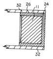
- an insulated glass assembly 30 incorporating the spacer 10 defined above, includes substrates 32 bonded to either side of the spacer body, with the desiccated matrix 22 and vapour barrier film 20 facing the interior of the assembly.
- a sealant such as silicone 24 may cover the outside (rear) face 14 of the spacer body.
- An insulated assembly thus formed in a particular one having the interior volume filled with an insulating gas such as argon or other noble gas, forms a highly effective insulator.
- the cellular arrangement of the spacer body, wherein the spacer core is formed from an array of chambers each trapping a volume of dead air or other gas, is highly effective as an insulator. It is contemplated that the assembly process of such an assembly is relatively simple, whereby the spacer material is simply bent around each corner during assembly of the various components, as seen in FIG. 4 .
- the spacer core 40 forms an essentially linear array of chambers, with both of the front and rear faces 42 and 44 of the core being undulating or sinusoidal in profile.
- the spacer core 40 forms a generally linear array of linked generally cylindrical members, each of which comprises a hollow chamber.
- the entire spacer core 40 is formed from hollow blow moulded PVC or vinyl as in the above version.
- the spacer core may be partly or fully encapsulated with sealant (not shown), with optionally an adhesive material on the flat upper and lower substrate engaging surfaces 46 .
- a third version of the spacer core is shown at FIGS. 5 and 6 and comprises a composite spacer core.
- the composite spacer core 50 of this version comprises paired linear arrays of hollow cellular members 52 , which are arranged in face to face staggered relationship.
- the opposing arrays are spaced apart to form an intersticial space between the arrays which may be filled by a matrix such as hot melt or PIB.
- the flat bases of the triangular members face the outside faces of the composite spacer core 50 , thereby forming a spacer core which may be bent around corners while maintaining a smooth exterior appearance.
- the insulated glass assembly shown herein comprises a double pane assembly. However, it will be appreciated that the same or similar arrangement may form a multi-pane assembly.
Abstract
An insulating spacer for use in glazing assemblies comprises a linear array of insulating chambers of linked cylindrical or semi-cylindrical shape. The spacer core may be formed from a semi-rigid material such as hollow blow moulded PVC or vinyl. A vapour barrier and desiccant matrix may be bonded to the interior face of the spacer core. As well, sealant material may cover at least partly the substrate engaging surfaces and/or the outside face of the spacer, to form a composite insulating spacer. The resulting spacer is energy efficient and relatively easy to manufacture and apply. An insulating glass assembly which incorporates such a spacer, is also provided.
Description
This application is a continuation-in-part of U.S. application Ser. No. 09/105,261, Jun. 26, 1998 abandoned, which is a divisional application of U.S. application Ser. No. 08/513,180 now U.S. Pat. No. 05/773,135, filed Aug. 9, 1995, which, in turn is a continuation-in-part application Ser. No. 08/477,950 now U.S. Pat. No. 05/616,415, filed Jun. 7, 1995, and issued on Apr. 1, 1997, which, in turn, is a continuation-in-part application of U.S. application Ser. No. 07/871,016 now U.S. Pat. No. 05/441,779, filed Apr. 20, 1992 and issued on Aug. 15, 1995.
This invention relates to insulated glass assemblies. In particular, it relates to a composite spacer for use in an insulated glass assembly and further relates to an insulated glass assembly incorporating such a spacer.
Insulated glass assemblies presently known in the art incorporate the use of various polymeric substances in combination with other materials. One such assembly includes a butylated polymer in which there is embedded an undulating metal spacer. Although useful, this type of sealant strip is limited in that the metal spacer, over time, becomes exposed to the substrates which results in a drastic depreciation in the efficiency of the strip. The particular difficulty arises with moisture vapour transmission when the spacer becomes exposed and contacts the substrates.
Further, many of the butylated polymers currently used in insulated glass assemblies are impregnated with a desiccant.
This results in a further problem, namely decreased adhesiveness of the butylated sealant.
Glover, et al. in U.S. Pat. No. 4,950,344, provide a spacer assembly including a foam body separated by a vapour barrier and further including a sealant means about the periphery of the assembly. Although this arrangement is particularly efficient from an energy point of view, one of the key limitations is that the assembly must be fabricated in a number of steps. Generally speaking, the sealant must be gunned about the periphery in a subsequent step to the initial placement of the spacer. This has ramifications during the manufacturing phase and is directly related to increased production costs and, therefore, increased costs in the assembly itself.
It has been found particularly advantageous to incorporate, as a major component of the spacer, a soft, resilient insulated body, having a low thermal conductivity. Examples of materials found to be useful include natural and synthetic elastomers (rubber), cork, EPDM, silicones, polyurethanes and foamed polysilicones, urethanes and other suitable foamed materials. Significant benefits arise from the choice of these materials since not only are they excellent insulators from an energy point of view but additionally, depending on the materials used, the entire spacer can maintain a certain degree of resiliency. This is important where windows, for example, engaged with such a strip experience fluctuating pressure forces as well as a thermal contraction and expansion. By making use of a resilient body, these stresses are alleviated and accordingly, the stress is not transferred to the substrates as would be the case, for example, in assemblies incorporating rigid spacers. However, an overly resilient spacer will tend to flex sideways, twist or compress either during the assembly process or subsequently when the insulated assembly is stressed.
Effective insulating spacers may achieve their effectiveness by trapping a volume of dead air. For example, the spacer body may comprise a thermal plastic or thermal setting foam material. However, conventional foam materials are typically relatively soft and may not be sufficiently rigid for use in association with insulating glass units. As well, a foam spacer formed essentially of a strip of foam material, having a rectangular cross-section, will tend to buckle at the spacer corners. Spacer buckling may be addressed either by rounding off the corners, which presents functional and aesthetic drawbacks, or by slitting and backfilling of the corners. The latter approach, while effective, requires a number of steps and may be relatively costly. Thus, there is a need for an insulating spacer material which has a degree of rigidity, readily forms sharp corners, and is relatively inexpensive and simple to fabricate and apply. Desirably, such a material traps a volume of dead air therein to achieve a superior level of insulation.
It would be desirable to have a composite spacer which overcomes the limitations of desiccated butyl as well as requiring the addition of sealant material in a subsequent procedure. The present invention is directed to satisfying the limitations in the known art.
The term “glass” herein also embraces plastics such as Plexiglass (tm) and the like.
An object of the present invention is to provide an improved spacer for use in insulated glass or glazing assemblies, the spacer incorporating a volume of dead air or other gas to achieve superior insulating qualities. A further object is to provide an improved insulated glass assembly incorporating such a spacer. A further object is to provide an improved spacer which is an effective insulator, while being relatively simple and inexpensive to manufacture and apply. A further object is to provide an insulating spacer which is relatively rigid and resists twisting and bending forces.
In accordance with the above objects, in one aspect the invention comprises a composite spacer for spacing substrates in an insulated glass assembly. The spacer comprises: an insulating spacer core having upper and lower flat substrate engaging surfaces, a front face for facing into the interior of said insulated glass assembly, and a rear face spaced apart from said front face. The spacer core comprises a generally linear array of cellular members. The rear face of the core is characterized by a regular array of deep indentations which define the individual members. In one version, the indentations are rounded to form a sinusoidal or undulating rear face. Alternatively, the members may be triangular or rectangular in cross-section. Preferably, the members each comprise a hollow, gas-filled chamber. In this version, the interior of said spacer core comprises an essentially linear array of hollow cells for trapping dead air therein, wherein said semi-cylindrical members each define a single cell. Conveniently, the spacer body is formed from blow moulded plastic such as PVC or vinyl.
In another aspect, both of the front and rear faces of the spacer core undulate to form an essentially linear array of generally cylindrical members, each of which defines a hollow cell or chamber.
In another aspect, a composite spacer is provided in which the rear face of the above spacer core is covered by a sealant material such as silicone or hot melt. In a further aspect, the substrate engaging surfaces of the spacer body are both covered with a sealant material such as a hot melt material. The front face preferably incorporates one or more of a vapour barrier film and a desiccant.
In another aspect, a composite spacer core comprises a pair of spacer cores in face to face relation, surrounded by hot melt or other flowable substrate to bind them together. For example, the spacer cover may each comprise an array of triangular members which interfinger when placed in face to face relationship.
In a further aspect, a clip is provided to hold neighboring spacer core cellular members in angled disposition to each other where the spacer extends around a corner.
The spacer core may be formed in a fully extruded fashion partly or fully surrounded by hot melt, Swizzle (TM) or other matrix. Alternatively, the spacer core may be co-extruded with one or more matrices such as desiccant, hot melt or other backing.
Preferably, the spacer core is formed from blow moulded PVC or vinyl, to form an essentially linear array of hollow cells or chambers, each cell having an outside sidewall being defined by an undulation of the spacer body.
The advantages achieved by a structure, include relatively high resistance to compressive forces as a result of the rigidity of the structure. As well, twisting and sideways bending of the spacer is minimized as a result of the spacer's relative rigidity. Preferably, the width of the spacer is sufficiently wide to minimize twisting and bending. As well, the undulations permit the spacer to form relatively sharp corners without slitting.
Suitable sealants include polyisobutylene (PIB) butyl or other butylated material which extends about the periphery of the assembly or at least on the flat substrate engaging surfaces of the spacer core and thereby provides a further sealed surface. Sealing or other adhesion for the insulating body may be achieved by providing special adhesives such as acrylic adhesive at the substrate engaging surfaces. Further, the material at the substrate engaging surfaces may be uncured so that on application of heat, the body adheres directly to the substrate. This is effective where there is provided at the substrate engaging surfaces a material composed of, for example, a ultra violet curable material.
The spacer may comprise a composite structure which includes as an integral component a desiccant matrix and/or vapour barrier film, on the front face of the spacer body. The desiccant material may be in the form of a matrix of a semi-permeable material. Various silicones with desiccant material disbursed therein are known to the art. Alternatively, where a separate matrix is not incorporated, a sealant material on the front face may include a desiccant material. Adhesive layers on the upper and lower faces permit the spacer to be mounted to substrates such as glass to form an IG unit.
In a further aspect, the invention comprises an insulating assembly, comprising spaced apart glass or plastic substrates, with a spacer of the type described above extending around the periphery of the assembly. A further layer of sealant material may be provided around the periphery of the assembly in contact with all or part of the rear face of the spacer.
FIG. 1 is a perspective view of a composite spacer according to the present invention;
FIG. 2 is a perspective view of an alternate embodiment of the spacer core illustrated at FIG. 1;
FIG. 3 is a sectional view of a portion of a glazing assembly illustrating the disposition of a spacer therein;
FIG. 4 illustrates the spacer of FIG. 1, in a flexed position to extend sharply around the corner of an insulated glass window assembly;
FIG. 5 is a sectional schematic view of a further embodiment of the invention, illustrating a spacer extending around a radius;
FIG. 6 is a schematic sectional view of the embodiment shown in FIG. 5;
FIG. 7 is a schematic sectional view of a further embodiment of the spacer core according to the present invention;
FIG. 8 is a schematic sectional view of a further embodiment of the spacer core;
FIG. 9 is a perspective view of a spacer core, illustrating a spacer corner clip according to the present invention; and
FIG. 10 is a perspective view, illustrating a composite spacer featuring a spacer core as shown in FIG. 1.
Referring to FIGS. 1, 3, 4 and 10, a first embodiment of a composite spacer 10 is illustrated. The spacer 10 comprises a spacer core 11, having a front face 12, which when the spacer is assembled within an insulating glass assembly, faces into the interior of the assembly, and a rear face 14 spaced apart from and opposed to the front face. The core 11 further includes upper and lower substrate engaging surfaces 16(a) and (b). In this version, the front face 12 of the spacer core is generally smooth, while the rear face 14 undulates or is sinusoidal in shape. The spacer body thus comprises a generally linear array of linked generally semicylindrical members 15. The top and bottom faces of the spacer comprise substrate engaging surfaces, and are substantially flat.
The spacer core is formed from blow moulded PVC or vinyl, with each of the cylindrical members being hollow. Thus, the spacer body comprises a linear array of generally hollow cells, the interior of each of which forms a dead air volume. Alternatively, the interiors may be filled with a gas having superior insulative qualities such as a noble gas. The individual cells or chambers which form the spacer body are preferably fully sealed from the external atmosphere.
The spacer core forms a component of a composite spacer. Bonded to the front face of the spacer core is a fluid barrier 20 to further prevent any exchange of gas or vapour with the interior of the insulated glass assembly. The fluid barrier may comprise a PET film which may further include an aluminum or other suitable metal layer. In addition, other metalized or non-metalized films may be used in this capacity.
The composite spacer may include a desiccant matrix 22 bonded to the fluid barrier at the front (interior) face of the spacer body. Suitable desiccant matrices are well known in the art and can include zeolite beads, silica gel, calcium chloride, etc., all of which may be matrixed within a semi-permeable flexible material such as a polysilicone or other suitable semi permeable substance. As a further option, the desiccant material may be incorporated into a continuing body of butyl material which covers at least partially the substrate engaging surfaces of the spacer body.
As seen in FIGS. 3 and 10, the spacer core 11 is at least partially encapsulated within a sealant material 24 which partially or fully covers the substrate engaging surfaces of the spacer core. The sealant may comprise hot melt or PIB, which is either co-extruded with the spacer core or alternatively may be applied in a secondary operation. The various components of the composite spacer may be of a uniform colour, or any combination of colours.
The substrate engaging surfaces 16(a) and (b) of the spacer 10 may also be partly or fully covered by an adhesive 26 to assist in the sealing and adhering engagement of a substrate with a respective side of the spacer core. The sealant and/or adhesive may comprise an uncured material capable of bonding with the substrates upon exposure to heat, ultraviolet radiation, or other curing agent.
As further illustrated in FIG. 3, an insulated glass assembly 30 incorporating the spacer 10 defined above, includes substrates 32 bonded to either side of the spacer body, with the desiccated matrix 22 and vapour barrier film 20 facing the interior of the assembly. A sealant such as silicone 24 may cover the outside (rear) face 14 of the spacer body. An insulated assembly thus formed, in a particular one having the interior volume filled with an insulating gas such as argon or other noble gas, forms a highly effective insulator. The cellular arrangement of the spacer body, wherein the spacer core is formed from an array of chambers each trapping a volume of dead air or other gas, is highly effective as an insulator. It is contemplated that the assembly process of such an assembly is relatively simple, whereby the spacer material is simply bent around each corner during assembly of the various components, as seen in FIG. 4.
In a further version of the spacer core, shown at FIG. 2, the spacer core 40 forms an essentially linear array of chambers, with both of the front and rear faces 42 and 44 of the core being undulating or sinusoidal in profile. In this version, the spacer core 40 forms a generally linear array of linked generally cylindrical members, each of which comprises a hollow chamber. The entire spacer core 40 is formed from hollow blow moulded PVC or vinyl as in the above version. The spacer core may be partly or fully encapsulated with sealant (not shown), with optionally an adhesive material on the flat upper and lower substrate engaging surfaces 46.
A third version of the spacer core is shown at FIGS. 5 and 6 and comprises a composite spacer core. The composite spacer core 50 of this version comprises paired linear arrays of hollow cellular members 52, which are arranged in face to face staggered relationship. The opposing arrays are spaced apart to form an intersticial space between the arrays which may be filled by a matrix such as hot melt or PIB. The flat bases of the triangular members face the outside faces of the composite spacer core 50, thereby forming a spacer core which may be bent around corners while maintaining a smooth exterior appearance.
FIGS. 7 and 8 illustrate a further embodiment of a spacer core 60. In this version, the cellular members are generally rectangular in section, and spaced apart. The intersticial spaces between the members is conveniently filled with a matrix such as hot melt or PIB. The individual members are mounted to a support matrix such as a vapour barrier film 20 to hold the spacer core together. The individual core members 62 comprise hollow cellular members as characterized above. As shown in FIG. 9, when this spacer core arrangement extends around a sharp corner, the cellular members 62 at the corner are spread apart by approximately 90 degrees. The invention further contemplates a spacer clip 64, which joins neighboring spacer core members at the point where the spacer extends around a corner. The clip includes gripper members 66 shaped to slide into the intersticial spaces between spacer core members, and retain neighboring core members together to prevent excess separation of neighboring members.
The insulated glass assembly shown herein comprises a double pane assembly. However, it will be appreciated that the same or similar arrangement may form a multi-pane assembly.
Claims (17)
1. An insulating glass assembly, comprising:
first and second glass substrates, and
an insulating spacer having spaced apart upper and lower substrate engaging surfaces engaging a respective surface of said first and second substrates, a front face facing the interior of said assembly and a rear face opposed to and spaced from said front face
said spacer having a core comprising a body having an undulating wall defining an array of individual hollow chambers, said hollow chambers enclosing a volume of air and extending in a direction between said first and second glass substrates.
2. An insulated glass assembly as defined in claim 1 , wherein said hollow chambers are air chambers, said spacer having top and bottom walls to thereby form enclosed air chambers and provide said upper and lower substrate engaging surfaces.
3. An insulated glass assembly as defined in claim 1 , wherein both of said front and rear faces are comprised of an undulating wall.
4. An insulated glass assembly as defined in claim 1 , wherein said rear face has a generally sinusoidal or wave shaped profile.
5. An insulated glass assembly as defined in claim 1 , wherein each of said chambers is a hollow gas-filled chamber.
6. An insulated glass assembly as defined in claim 1 , wherein said spacer is formed from blow moulded PVC or vinyl.
7. An insulated glass assembly as defined in claim 1 , wherein said spacer core is at least partially encapsulated within a sealant material.
8. An insulated glass assembly as defined in claim 1 , wherein said front face of said spacer core is generally smooth within a fluid barrier means at said front face.
9. An Insulated glass assembly as defined in claim 8 , where there is bonded to said fluid barrier means a desiccant containing matrix.
10. An insulated glass assembly as defined in claim 1 , wherein said substrate engaging surfaces are at least partly covered by an adhesive.
11. An insulated glass assembly as defined in claim 1 , wherein both of said front and rear faces have an undulating profile to form an essentially linear array of linked chambers.
12. An insulated glass assembly as defined in claim 11 , wherein both of said front and rear faces have an wave shaped or generally sinusoidal profile to form an essentially linear array of linked chambers.
13. An insulated glass assembly as defined in claim 12 , wherein each of said chambers is gas-filled.
14. An insulated glass assembly as defined in claim 13 , wherein each of said chambers is generally triangular in cross-section.
15. An insulated glass assembly as defined in claim 14 , further comprising a second spacer core, arrange in an offset relationship thereto to form a composite spacer core, the apices of said triangular members facing into the interior of said composite spacer core and the fiat bases facing the exterior thereof, said spacer core being spaced apart to form ain intersticial space therebetween, said intersticial space being filled with a matrix.
16. An insulated glass assembly as defined in claim 14 , wherein said chambers are generally rectangular in cross-section and spaced apart from each other, said members being joined together by a support matrix forming said front face of said spacer core.
17. An insulated glass assembly as defined in claim 15 , comprising a clip member for engaging adjacent or near-adjacent spacer core chambers to restrict separation thereof at a corner, said clip member comprising a generally L-shaped member having engagement means to engage with corresponding spacer core chambers.
Priority Applications (1)
| Application Number | Priority Date | Filing Date | Title |
|---|---|---|---|
| US09/553,320 US6528131B1 (en) | 1991-04-22 | 2000-04-20 | Insulated assembly incorporating a thermoplastic barrier member |
Applications Claiming Priority (7)
| Application Number | Priority Date | Filing Date | Title |
|---|---|---|---|
| CA2040636 | 1991-04-22 | ||
| CA2040636 | 1991-04-22 | ||
| US07/871,016 US5441779A (en) | 1991-04-22 | 1992-04-20 | Insulated assembly incorporating a thermoplastic barrier member |
| US08/477,950 US5616415A (en) | 1991-04-22 | 1995-06-07 | Insulated assembly incorporating a thermoplastic barrier member |
| US08/513,180 US5773135A (en) | 1991-04-22 | 1995-08-09 | Insulated assembly incorporating a thermoplastic barrier member |
| US10526198A | 1998-06-26 | 1998-06-26 | |
| US09/553,320 US6528131B1 (en) | 1991-04-22 | 2000-04-20 | Insulated assembly incorporating a thermoplastic barrier member |
Related Parent Applications (1)
| Application Number | Title | Priority Date | Filing Date |
|---|---|---|---|
| US10526198A Continuation-In-Part | 1991-04-22 | 1998-06-26 |
Publications (1)
| Publication Number | Publication Date |
|---|---|
| US6528131B1 true US6528131B1 (en) | 2003-03-04 |
Family
ID=27508427
Family Applications (1)
| Application Number | Title | Priority Date | Filing Date |
|---|---|---|---|
| US09/553,320 Expired - Fee Related US6528131B1 (en) | 1991-04-22 | 2000-04-20 | Insulated assembly incorporating a thermoplastic barrier member |
Country Status (1)
| Country | Link |
|---|---|
| US (1) | US6528131B1 (en) |
Cited By (39)
| Publication number | Priority date | Publication date | Assignee | Title |
|---|---|---|---|---|
| US20030038528A1 (en) * | 2000-08-22 | 2003-02-27 | Youngi Kim | Pocket wheel cover for portable golf cart |
| US20030074859A1 (en) * | 2001-08-09 | 2003-04-24 | Gerhard Reichert | Spacer assembly for insulating glazing units and method for fabricating the same |
| US20040076815A1 (en) * | 2002-07-03 | 2004-04-22 | Gerhard Reichert | Spacer and muntin elements for insulating glazing units |
| US20040169593A1 (en) * | 1999-04-02 | 2004-09-02 | Robert Olodort | Foldable keyboard |
| US20050028458A1 (en) * | 2003-06-23 | 2005-02-10 | Rosskamp Barent A. | Integrated window sash with lattice frame and retainer clip |
| US20050028459A1 (en) * | 2003-06-23 | 2005-02-10 | Crandell Stephen L. | Method of making an integrated window sash |
| US20050028460A1 (en) * | 2003-06-23 | 2005-02-10 | Steffek Cory D. | Integrated window sash |
| US20050034386A1 (en) * | 2003-06-23 | 2005-02-17 | Crandell Stephen L. | Integrated window sash with groove for desiccant material |
| US6989188B2 (en) | 2003-11-07 | 2006-01-24 | Technoform Caprano Und Brunnhofer Gmbh & Co. Kd | Spacer profiles for double glazings |
| US20060101739A1 (en) * | 2000-11-08 | 2006-05-18 | Afg Industries, Inc. | Ribbed tube continuous flexible spacer assembly |
| US20060159874A1 (en) * | 2005-01-18 | 2006-07-20 | Solutia, Inc. | Windows having multiple polymer layers |
| US20060157186A1 (en) * | 2005-01-18 | 2006-07-20 | Solutia, Inc. | Methods for producing windows having multiple polymer layers |
| US20070261325A1 (en) * | 2003-06-23 | 2007-11-15 | Rosskamp Barent A | Plastic spacer stock, plastic spacer frame and multi-sheet unit, and method of making same |
| US20070261358A1 (en) * | 2003-06-23 | 2007-11-15 | Davis William B | Plastic spacer stock, plastic spacer frame and multi-sheet unit, and method of making same |
| US20070275192A1 (en) * | 2006-05-24 | 2007-11-29 | Peter Lisec | Insulating Glass Unit with an Elastoplastic Spacer Strip and a Method of Applying the Spacer Strip |
| US20090120018A1 (en) * | 2007-11-13 | 2009-05-14 | Infinite Edge Technologies, Llc | Sealed unit and spacer with stabilized elongate strip |
| US7827761B2 (en) | 2003-06-23 | 2010-11-09 | Ppg Industries Ohio, Inc. | Plastic spacer stock, plastic spacer frame and multi-sheet unit, and method of making same |
| US7852996B2 (en) | 2001-08-29 | 2010-12-14 | Google Inc. | Method and system for providing information for identifying callers based on partial number |
| US20110104512A1 (en) * | 2009-07-14 | 2011-05-05 | Rapp Eric B | Stretched strips for spacer and sealed unit |
| US7950194B2 (en) | 2003-06-23 | 2011-05-31 | Ppg Industries Ohio, Inc. | Plastic spacer stock, plastic spacer frame and multi-sheet unit, and method of making same |
| US20120159880A1 (en) * | 2010-12-23 | 2012-06-28 | Saint-Gobain Performance Plastics Corporatrion | Structural Glazing Spacer |
| US8230661B2 (en) | 2000-10-20 | 2012-07-31 | Truseal Technologies, Inc. | Continuous flexible spacer assembly having sealant support member |
| WO2012140005A1 (en) * | 2011-04-13 | 2012-10-18 | Prowerb Ag | Spacer for spacing apart glass panes in a multi-glazed window, a multi-glazed window and a process for producing a spacer |
| US8967219B2 (en) | 2010-06-10 | 2015-03-03 | Guardian Ig, Llc | Window spacer applicator |
| USD732697S1 (en) | 2013-11-27 | 2015-06-23 | Vinyl-Pro Window Systems, Inc. | Decorative scroll for a window |
| US9140052B2 (en) | 2013-11-27 | 2015-09-22 | Vinyl-Pro Window Systems Inc. | Decorative insert for a window |
| US9228389B2 (en) | 2010-12-17 | 2016-01-05 | Guardian Ig, Llc | Triple pane window spacer, window assembly and methods for manufacturing same |
| US9260907B2 (en) | 2012-10-22 | 2016-02-16 | Guardian Ig, Llc | Triple pane window spacer having a sunken intermediate pane |
| US9309714B2 (en) | 2007-11-13 | 2016-04-12 | Guardian Ig, Llc | Rotating spacer applicator for window assembly |
| US20160278204A1 (en) * | 2014-12-05 | 2016-09-22 | VivaLnk, Inc. | Stretchable electronic patch having a foldable circuit layer |
| US20160290032A1 (en) * | 2013-12-12 | 2016-10-06 | Saint-Gobain Glass France | Spacer for insulating glazing units, comprising extruded profiled seal |
| US9689196B2 (en) | 2012-10-22 | 2017-06-27 | Guardian Ig, Llc | Assembly equipment line and method for windows |
| US10190359B2 (en) | 2013-12-12 | 2019-01-29 | Saint-Gobain Glass France | Double glazing having improved sealing |
| US10301868B2 (en) | 2014-06-27 | 2019-05-28 | Saint-Gobain Glass France | Insulated glazing comprising a spacer, and production method |
| US10344525B2 (en) | 2014-06-27 | 2019-07-09 | Saint-Gobain Glass France | Insulated glazing with spacer, related methods and uses |
| US10508486B2 (en) | 2015-03-02 | 2019-12-17 | Saint Gobain Glass France | Glass-fiber-reinforced spacer for insulating glazing unit |
| US10626663B2 (en) | 2014-09-25 | 2020-04-21 | Saint-Gobain Glass France | Spacer for insulating glazing units |
| US10632708B2 (en) * | 2016-02-29 | 2020-04-28 | Alienus Film Llc | Insulating film |
| AU2017346393B2 (en) * | 2016-10-18 | 2023-09-07 | P.E.T. Polymer Extrusion Technology, Inc. | Method and system for manufacturing a spacer for translucent panels |
Citations (25)
| Publication number | Priority date | Publication date | Assignee | Title |
|---|---|---|---|---|
| US2253219A (en) * | 1939-02-16 | 1941-08-19 | Elmo E Alexander | Panel bend |
| US3027608A (en) | 1959-06-22 | 1962-04-03 | Libbey Owens Ford Glass Co | Multiple glass sheet glazing units |
| US3544294A (en) | 1966-10-08 | 1970-12-01 | Tokyo Shibaura Electric Co | Method for manufacturing laminated glass plates |
| US3578543A (en) * | 1967-09-28 | 1971-05-11 | Ethyl Corp | Seal for plastic sheeting |
| US3607596A (en) * | 1968-07-10 | 1971-09-21 | Fmc Corp | Cellular article |
| US3791910A (en) | 1972-03-07 | 1974-02-12 | Ppg Industries Inc | Multiple glazed unit |
| US3823524A (en) | 1973-01-12 | 1974-07-16 | Alusuisse | Thermal break type architectural extrusions |
| US4113905A (en) | 1977-01-06 | 1978-09-12 | Gerald Kessler | D.i.g. foam spacer |
| US4268553A (en) | 1978-04-05 | 1981-05-19 | Usm Corporation | Method for double glazing units |
| US4335166A (en) | 1980-11-21 | 1982-06-15 | Cardinal Insulated Glass Co. | Method of manufacturing a multiple-pane insulating glass unit |
| US4348435A (en) | 1980-03-19 | 1982-09-07 | Ppg Industries, Inc. | Primed multiple glazed units for curtainwall systems |
| US4393105A (en) | 1981-04-20 | 1983-07-12 | Spire Corporation | Method of fabricating a thermal pane window and product |
| US4431691A (en) * | 1979-01-29 | 1984-02-14 | Tremco, Incorporated | Dimensionally stable sealant and spacer strip and composite structures comprising the same |
| US4576841A (en) | 1981-11-04 | 1986-03-18 | Helmut Lingemann Gmbh & Co. | Desiccant application for double-glazed windows, etc. and a spacer section filled with the desiccant application |
| US4658553A (en) | 1984-07-25 | 1987-04-21 | Sanden Corporation | Multi-windowpane structure for use in a temperature controlled environment |
| US4822649A (en) | 1986-02-20 | 1989-04-18 | Saint-Gobain Vitrage | Multiple glazing, method for obtaining same and device for using said method |
| US4831799A (en) | 1986-09-22 | 1989-05-23 | Michael Glover | Multiple layer insulated glazing units |
| US4950344A (en) | 1988-12-05 | 1990-08-21 | Lauren Manufacturing Company | Method of manufacturing multiple-pane sealed glazing units |
| US5007217A (en) | 1986-09-22 | 1991-04-16 | Lauren Manufacturing Company | Multiple pane sealed glazing unit |
| US5048997A (en) | 1989-08-16 | 1991-09-17 | Alumet Mfg. Inc. | Flexible cornerpiece for spacer frame for insulated glass panel |
| US5106663A (en) | 1989-03-07 | 1992-04-21 | Tremco Incorporated | Double-paned window system having controlled sealant thickness |
| US5120584A (en) | 1987-08-31 | 1992-06-09 | Saint-Gobain Vitrage | Insulating glass pane for motor vehicles |
| US5128181A (en) | 1989-02-07 | 1992-07-07 | Heinz Kunert | Construction element |
| US5196254A (en) * | 1986-07-25 | 1993-03-23 | Jsp Corporation | Cushioning material |
| US5234730A (en) * | 1986-11-07 | 1993-08-10 | Tremco, Inc. | Adhesive composition, process, and product |
-
2000
- 2000-04-20 US US09/553,320 patent/US6528131B1/en not_active Expired - Fee Related
Patent Citations (25)
| Publication number | Priority date | Publication date | Assignee | Title |
|---|---|---|---|---|
| US2253219A (en) * | 1939-02-16 | 1941-08-19 | Elmo E Alexander | Panel bend |
| US3027608A (en) | 1959-06-22 | 1962-04-03 | Libbey Owens Ford Glass Co | Multiple glass sheet glazing units |
| US3544294A (en) | 1966-10-08 | 1970-12-01 | Tokyo Shibaura Electric Co | Method for manufacturing laminated glass plates |
| US3578543A (en) * | 1967-09-28 | 1971-05-11 | Ethyl Corp | Seal for plastic sheeting |
| US3607596A (en) * | 1968-07-10 | 1971-09-21 | Fmc Corp | Cellular article |
| US3791910A (en) | 1972-03-07 | 1974-02-12 | Ppg Industries Inc | Multiple glazed unit |
| US3823524A (en) | 1973-01-12 | 1974-07-16 | Alusuisse | Thermal break type architectural extrusions |
| US4113905A (en) | 1977-01-06 | 1978-09-12 | Gerald Kessler | D.i.g. foam spacer |
| US4268553A (en) | 1978-04-05 | 1981-05-19 | Usm Corporation | Method for double glazing units |
| US4431691A (en) * | 1979-01-29 | 1984-02-14 | Tremco, Incorporated | Dimensionally stable sealant and spacer strip and composite structures comprising the same |
| US4348435A (en) | 1980-03-19 | 1982-09-07 | Ppg Industries, Inc. | Primed multiple glazed units for curtainwall systems |
| US4335166A (en) | 1980-11-21 | 1982-06-15 | Cardinal Insulated Glass Co. | Method of manufacturing a multiple-pane insulating glass unit |
| US4393105A (en) | 1981-04-20 | 1983-07-12 | Spire Corporation | Method of fabricating a thermal pane window and product |
| US4576841A (en) | 1981-11-04 | 1986-03-18 | Helmut Lingemann Gmbh & Co. | Desiccant application for double-glazed windows, etc. and a spacer section filled with the desiccant application |
| US4658553A (en) | 1984-07-25 | 1987-04-21 | Sanden Corporation | Multi-windowpane structure for use in a temperature controlled environment |
| US4822649A (en) | 1986-02-20 | 1989-04-18 | Saint-Gobain Vitrage | Multiple glazing, method for obtaining same and device for using said method |
| US5196254A (en) * | 1986-07-25 | 1993-03-23 | Jsp Corporation | Cushioning material |
| US4831799A (en) | 1986-09-22 | 1989-05-23 | Michael Glover | Multiple layer insulated glazing units |
| US5007217A (en) | 1986-09-22 | 1991-04-16 | Lauren Manufacturing Company | Multiple pane sealed glazing unit |
| US5234730A (en) * | 1986-11-07 | 1993-08-10 | Tremco, Inc. | Adhesive composition, process, and product |
| US5120584A (en) | 1987-08-31 | 1992-06-09 | Saint-Gobain Vitrage | Insulating glass pane for motor vehicles |
| US4950344A (en) | 1988-12-05 | 1990-08-21 | Lauren Manufacturing Company | Method of manufacturing multiple-pane sealed glazing units |
| US5128181A (en) | 1989-02-07 | 1992-07-07 | Heinz Kunert | Construction element |
| US5106663A (en) | 1989-03-07 | 1992-04-21 | Tremco Incorporated | Double-paned window system having controlled sealant thickness |
| US5048997A (en) | 1989-08-16 | 1991-09-17 | Alumet Mfg. Inc. | Flexible cornerpiece for spacer frame for insulated glass panel |
Cited By (64)
| Publication number | Priority date | Publication date | Assignee | Title |
|---|---|---|---|---|
| US20040169593A1 (en) * | 1999-04-02 | 2004-09-02 | Robert Olodort | Foldable keyboard |
| US20030038528A1 (en) * | 2000-08-22 | 2003-02-27 | Youngi Kim | Pocket wheel cover for portable golf cart |
| US8230661B2 (en) | 2000-10-20 | 2012-07-31 | Truseal Technologies, Inc. | Continuous flexible spacer assembly having sealant support member |
| US7107729B2 (en) | 2000-11-08 | 2006-09-19 | Afg Industries, Inc. | Ribbed tube continuous flexible spacer assembly |
| US8281527B2 (en) | 2000-11-08 | 2012-10-09 | Agc Flat Glass North America, Inc. | Ribbed tube continuous flexible spacer assembly |
| US20060101739A1 (en) * | 2000-11-08 | 2006-05-18 | Afg Industries, Inc. | Ribbed tube continuous flexible spacer assembly |
| US20030074859A1 (en) * | 2001-08-09 | 2003-04-24 | Gerhard Reichert | Spacer assembly for insulating glazing units and method for fabricating the same |
| US7743584B2 (en) * | 2001-08-09 | 2010-06-29 | Edgetech I.G., Inc. | Spacer assembly for insulating glazing units and method for fabricating the same |
| US7852996B2 (en) | 2001-08-29 | 2010-12-14 | Google Inc. | Method and system for providing information for identifying callers based on partial number |
| US20040076815A1 (en) * | 2002-07-03 | 2004-04-22 | Gerhard Reichert | Spacer and muntin elements for insulating glazing units |
| US20050166546A1 (en) * | 2002-07-03 | 2005-08-04 | Gerhard Reichert | Spacer for insulating glazing units |
| US7997037B2 (en) | 2003-06-23 | 2011-08-16 | Ppg Industries Ohio, Inc. | Integrated window sash with groove for desiccant material |
| US7739851B2 (en) | 2003-06-23 | 2010-06-22 | Ppg Industries Ohio, Inc. | Plastic spacer stock, plastic spacer frame and multi-sheet unit, and method of making same |
| US7856791B2 (en) | 2003-06-23 | 2010-12-28 | Ppg Industries Ohio, Inc. | Plastic spacer stock, plastic spacer frame and multi-sheet unit, and method of making same |
| US20070261325A1 (en) * | 2003-06-23 | 2007-11-15 | Rosskamp Barent A | Plastic spacer stock, plastic spacer frame and multi-sheet unit, and method of making same |
| US20070261358A1 (en) * | 2003-06-23 | 2007-11-15 | Davis William B | Plastic spacer stock, plastic spacer frame and multi-sheet unit, and method of making same |
| US20050034386A1 (en) * | 2003-06-23 | 2005-02-17 | Crandell Stephen L. | Integrated window sash with groove for desiccant material |
| US7490445B2 (en) | 2003-06-23 | 2009-02-17 | Ppg Industries Ohio, Inc. | Integrated window sash |
| US7827761B2 (en) | 2003-06-23 | 2010-11-09 | Ppg Industries Ohio, Inc. | Plastic spacer stock, plastic spacer frame and multi-sheet unit, and method of making same |
| US20050028458A1 (en) * | 2003-06-23 | 2005-02-10 | Rosskamp Barent A. | Integrated window sash with lattice frame and retainer clip |
| US20050028459A1 (en) * | 2003-06-23 | 2005-02-10 | Crandell Stephen L. | Method of making an integrated window sash |
| US20050028460A1 (en) * | 2003-06-23 | 2005-02-10 | Steffek Cory D. | Integrated window sash |
| US7588653B2 (en) | 2003-06-23 | 2009-09-15 | Ppg Industries Ohio, Inc. | Method of making an integrated window sash |
| US7765769B2 (en) | 2003-06-23 | 2010-08-03 | Ppg Industries Ohio, Inc. | Integrated window sash with lattice frame and retainer clip |
| US7950194B2 (en) | 2003-06-23 | 2011-05-31 | Ppg Industries Ohio, Inc. | Plastic spacer stock, plastic spacer frame and multi-sheet unit, and method of making same |
| US6989188B2 (en) | 2003-11-07 | 2006-01-24 | Technoform Caprano Und Brunnhofer Gmbh & Co. Kd | Spacer profiles for double glazings |
| US20060157186A1 (en) * | 2005-01-18 | 2006-07-20 | Solutia, Inc. | Methods for producing windows having multiple polymer layers |
| US20060159874A1 (en) * | 2005-01-18 | 2006-07-20 | Solutia, Inc. | Windows having multiple polymer layers |
| US7713600B2 (en) * | 2006-05-24 | 2010-05-11 | Peter Lisec | Insulating glass unit with an elastoplastic spacer strip and a method of applying the spacer strip |
| US20070275192A1 (en) * | 2006-05-24 | 2007-11-29 | Peter Lisec | Insulating Glass Unit with an Elastoplastic Spacer Strip and a Method of Applying the Spacer Strip |
| US20090120036A1 (en) * | 2007-11-13 | 2009-05-14 | Infinite Edge Technologies, Llc | Box spacer with sidewalls |
| US9617781B2 (en) | 2007-11-13 | 2017-04-11 | Guardian Ig, Llc | Sealed unit and spacer |
| US20090120019A1 (en) * | 2007-11-13 | 2009-05-14 | Infinite Edge Technologies, Llc | Reinforced window spacer |
| US8151542B2 (en) * | 2007-11-13 | 2012-04-10 | Infinite Edge Technologies, Llc | Box spacer with sidewalls |
| US9309714B2 (en) | 2007-11-13 | 2016-04-12 | Guardian Ig, Llc | Rotating spacer applicator for window assembly |
| US20090123694A1 (en) * | 2007-11-13 | 2009-05-14 | Infinite Edge Technologies, Llc | Material with undulating shape |
| US9127502B2 (en) | 2007-11-13 | 2015-09-08 | Guardian Ig, Llc | Sealed unit and spacer |
| US9187949B2 (en) | 2007-11-13 | 2015-11-17 | Guardian Ig, Llc | Spacer joint structure |
| US20090120018A1 (en) * | 2007-11-13 | 2009-05-14 | Infinite Edge Technologies, Llc | Sealed unit and spacer with stabilized elongate strip |
| US8596024B2 (en) | 2007-11-13 | 2013-12-03 | Infinite Edge Technologies, Llc | Sealed unit and spacer |
| US8795568B2 (en) | 2007-11-13 | 2014-08-05 | Guardian Ig, Llc | Method of making a box spacer with sidewalls |
| US8586193B2 (en) | 2009-07-14 | 2013-11-19 | Infinite Edge Technologies, Llc | Stretched strips for spacer and sealed unit |
| US20110104512A1 (en) * | 2009-07-14 | 2011-05-05 | Rapp Eric B | Stretched strips for spacer and sealed unit |
| US8967219B2 (en) | 2010-06-10 | 2015-03-03 | Guardian Ig, Llc | Window spacer applicator |
| US9228389B2 (en) | 2010-12-17 | 2016-01-05 | Guardian Ig, Llc | Triple pane window spacer, window assembly and methods for manufacturing same |
| US8826611B2 (en) * | 2010-12-23 | 2014-09-09 | Saint-Gobain Performance Plastics Corporation | Structural glazing spacer |
| US9272499B2 (en) | 2010-12-23 | 2016-03-01 | Saint-Gobain Performance Plastics Corporation | Structural glazing spacer |
| US20120159880A1 (en) * | 2010-12-23 | 2012-06-28 | Saint-Gobain Performance Plastics Corporatrion | Structural Glazing Spacer |
| WO2012140005A1 (en) * | 2011-04-13 | 2012-10-18 | Prowerb Ag | Spacer for spacing apart glass panes in a multi-glazed window, a multi-glazed window and a process for producing a spacer |
| US9260907B2 (en) | 2012-10-22 | 2016-02-16 | Guardian Ig, Llc | Triple pane window spacer having a sunken intermediate pane |
| US9689196B2 (en) | 2012-10-22 | 2017-06-27 | Guardian Ig, Llc | Assembly equipment line and method for windows |
| USD732697S1 (en) | 2013-11-27 | 2015-06-23 | Vinyl-Pro Window Systems, Inc. | Decorative scroll for a window |
| US9140052B2 (en) | 2013-11-27 | 2015-09-22 | Vinyl-Pro Window Systems Inc. | Decorative insert for a window |
| US20160290032A1 (en) * | 2013-12-12 | 2016-10-06 | Saint-Gobain Glass France | Spacer for insulating glazing units, comprising extruded profiled seal |
| US10167665B2 (en) * | 2013-12-12 | 2019-01-01 | Saint-Gobain Glass France | Spacer for insulating glazing units, comprising extruded profiled seal |
| US10190359B2 (en) | 2013-12-12 | 2019-01-29 | Saint-Gobain Glass France | Double glazing having improved sealing |
| US10301868B2 (en) | 2014-06-27 | 2019-05-28 | Saint-Gobain Glass France | Insulated glazing comprising a spacer, and production method |
| US10344525B2 (en) | 2014-06-27 | 2019-07-09 | Saint-Gobain Glass France | Insulated glazing with spacer, related methods and uses |
| US10626663B2 (en) | 2014-09-25 | 2020-04-21 | Saint-Gobain Glass France | Spacer for insulating glazing units |
| US9585245B2 (en) * | 2014-12-05 | 2017-02-28 | VivaLnk, Inc. | Stretchable electronic patch having a foldable circuit layer |
| US20160278204A1 (en) * | 2014-12-05 | 2016-09-22 | VivaLnk, Inc. | Stretchable electronic patch having a foldable circuit layer |
| US10508486B2 (en) | 2015-03-02 | 2019-12-17 | Saint Gobain Glass France | Glass-fiber-reinforced spacer for insulating glazing unit |
| US10632708B2 (en) * | 2016-02-29 | 2020-04-28 | Alienus Film Llc | Insulating film |
| AU2017346393B2 (en) * | 2016-10-18 | 2023-09-07 | P.E.T. Polymer Extrusion Technology, Inc. | Method and system for manufacturing a spacer for translucent panels |
Similar Documents
| Publication | Publication Date | Title |
|---|---|---|
| US6528131B1 (en) | Insulated assembly incorporating a thermoplastic barrier member | |
| CA2408382C (en) | Insulated assembly incorporating a thermoplastic barrier member | |
| EP0865560B1 (en) | Insulated assembly incorporating a thermoplastic barrier member and a spacer adapted for use as such a barrier member. | |
| US5806272A (en) | Foam core spacer assembly | |
| US5691045A (en) | Insulated assembly incorporating a thermoplastic barrier member | |
| US5088258A (en) | Thermal broken glass spacer | |
| EP0610274B1 (en) | Insulation strip and method for single and multiple atmosphere insulating assemblies | |
| US5658645A (en) | Insulation strip and method for single and multiple atmosphere insulating assemblies | |
| EP1341982B1 (en) | Ribbed tube continuous flexible spacer assembly | |
| US5447761A (en) | Sealant strip incorporating flexing stress alleviating means | |
| CA2303464C (en) | Spacer for insulated glass assembly | |
| US20220316264A1 (en) | Compression Fit Grooved Spacer | |
| CN114585793B (en) | Compression fit channel spacer | |
| JP3866287B6 (en) | Thermal insulation assembly incorporating a thermoplastic barrier member | |
| CA2054272C (en) | Insulation strip and method for single and multiple atmosphere insulating assemblies | |
| MXPA00004833A (en) | Spacer for insulated glass assembly |
Legal Events
| Date | Code | Title | Description |
|---|---|---|---|
| FPAY | Fee payment |
Year of fee payment: 4 |
|
| FPAY | Fee payment |
Year of fee payment: 8 |
|
| REMI | Maintenance fee reminder mailed | ||
| LAPS | Lapse for failure to pay maintenance fees | ||
| STCH | Information on status: patent discontinuation |
Free format text: PATENT EXPIRED DUE TO NONPAYMENT OF MAINTENANCE FEES UNDER 37 CFR 1.362 |
|
| FP | Expired due to failure to pay maintenance fee |
Effective date: 20150304 |