US6529669B1 - Cable junction box, particularly for optical fibers - Google Patents
Cable junction box, particularly for optical fibers Download PDFInfo
- Publication number
- US6529669B1 US6529669B1 US09/246,910 US24691099A US6529669B1 US 6529669 B1 US6529669 B1 US 6529669B1 US 24691099 A US24691099 A US 24691099A US 6529669 B1 US6529669 B1 US 6529669B1
- Authority
- US
- United States
- Prior art keywords
- cable
- junction box
- support base
- box
- box according
- Prior art date
- Legal status (The legal status is an assumption and is not a legal conclusion. Google has not performed a legal analysis and makes no representation as to the accuracy of the status listed.)
- Expired - Fee Related
Links
- 239000013307 optical fiber Substances 0.000 title abstract description 9
- 239000000835 fiber Substances 0.000 claims abstract description 34
- 125000006850 spacer group Chemical group 0.000 claims abstract description 9
- 238000009434 installation Methods 0.000 abstract description 2
- 238000012423 maintenance Methods 0.000 abstract 1
- 230000003287 optical effect Effects 0.000 description 9
- 238000000034 method Methods 0.000 description 8
- 239000000969 carrier Substances 0.000 description 6
- 238000004519 manufacturing process Methods 0.000 description 5
- 238000009826 distribution Methods 0.000 description 4
- 239000013521 mastic Substances 0.000 description 3
- 238000013461 design Methods 0.000 description 2
- 238000011161 development Methods 0.000 description 2
- 238000010586 diagram Methods 0.000 description 2
- 230000010354 integration Effects 0.000 description 2
- 239000000463 material Substances 0.000 description 2
- 230000008520 organization Effects 0.000 description 2
- 238000007789 sealing Methods 0.000 description 2
- 238000004804 winding Methods 0.000 description 2
- 241000531908 Aramides Species 0.000 description 1
- 241000252203 Clupea harengus Species 0.000 description 1
- RYGMFSIKBFXOCR-UHFFFAOYSA-N Copper Chemical compound [Cu] RYGMFSIKBFXOCR-UHFFFAOYSA-N 0.000 description 1
- 238000004026 adhesive bonding Methods 0.000 description 1
- 238000004873 anchoring Methods 0.000 description 1
- 238000013459 approach Methods 0.000 description 1
- 229920003235 aromatic polyamide Polymers 0.000 description 1
- 230000005540 biological transmission Effects 0.000 description 1
- 210000000988 bone and bone Anatomy 0.000 description 1
- 239000002131 composite material Substances 0.000 description 1
- 230000006835 compression Effects 0.000 description 1
- 238000007906 compression Methods 0.000 description 1
- 229910052802 copper Inorganic materials 0.000 description 1
- 239000010949 copper Substances 0.000 description 1
- 238000005520 cutting process Methods 0.000 description 1
- 239000011152 fibreglass Substances 0.000 description 1
- 210000004907 gland Anatomy 0.000 description 1
- 235000019514 herring Nutrition 0.000 description 1
- 229920001903 high density polyethylene Polymers 0.000 description 1
- 239000004700 high-density polyethylene Substances 0.000 description 1
- 238000002347 injection Methods 0.000 description 1
- 239000007924 injection Substances 0.000 description 1
- 239000004033 plastic Substances 0.000 description 1
- 229920003023 plastic Polymers 0.000 description 1
- 229920002635 polyurethane Polymers 0.000 description 1
- 239000004814 polyurethane Substances 0.000 description 1
- 238000002360 preparation method Methods 0.000 description 1
- 239000011347 resin Substances 0.000 description 1
- 229920005989 resin Polymers 0.000 description 1
- 230000000717 retained effect Effects 0.000 description 1
- 239000013585 weight reducing agent Substances 0.000 description 1
- 238000003466 welding Methods 0.000 description 1
Images


Classifications
-
- G—PHYSICS
- G02—OPTICS
- G02B—OPTICAL ELEMENTS, SYSTEMS OR APPARATUS
- G02B6/00—Light guides; Structural details of arrangements comprising light guides and other optical elements, e.g. couplings
- G02B6/44—Mechanical structures for providing tensile strength and external protection for fibres, e.g. optical transmission cables
- G02B6/4439—Auxiliary devices
- G02B6/4471—Terminating devices ; Cable clamps
- G02B6/4472—Manifolds
- G02B6/4475—Manifolds with provision for lateral branching
-
- G—PHYSICS
- G02—OPTICS
- G02B—OPTICAL ELEMENTS, SYSTEMS OR APPARATUS
- G02B6/00—Light guides; Structural details of arrangements comprising light guides and other optical elements, e.g. couplings
- G02B6/44—Mechanical structures for providing tensile strength and external protection for fibres, e.g. optical transmission cables
- G02B6/4439—Auxiliary devices
- G02B6/444—Systems or boxes with surplus lengths
- G02B6/4441—Boxes
- G02B6/4446—Cable boxes, e.g. splicing boxes with two or more multi fibre cables
Definitions
- the invention relates to a junction box for a tensioned cable, particularly an optical fibers cable.
- the invention is applicable for making branch connections on line or in a section operated on cables.
- making a branch connection is an operation that consists of connecting one or several wires or one or several cable fibers to connect them to another cable.
- connection technique is a relatively recent technique used for optical fiber cables that consists of cutting the optical fiber(s) to be connected, to connect it or them to other fibers in another cable.
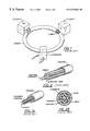
- FIG. 1 illustrates the principle used for making branch connections to this type of network.
- the invention can be better understood after a brief reminder about the development of the structure of currently available optical fibers.
- the first cables specially designed for the production of inter-city networks are cables with grooved rods as illustrated in FIG. 2 .
- the cable with tubes technique was subsequently developed in order to better protect the fiber and also to encase it.
- FIGS. 2A and 2B These cables are illustrated in FIGS. 2A and 2B.
- looped networks naturally protected by a return along a different route, improve reliability. For example, they were used for the connection of large cooperations (for example banks).
- single-tube cables is characterized (in cables containing up to 288 fibers) by a thick high density polyethylene tube containing 2 or 4 carriers. These carriers stabilize the materials. In fact, they are made of a fiber glass composite or aramide wick. Laying is facilitated by their high tensile and compression strength.
- Encasing of the fibers making up single-tube cables leads to two types of optical modules, namely ribbon fibers and fibers with flexible casings.
- Ribbon fibers or flat cable fibers are placed side by side in a polymerized casing. This encasing is done in the factory, and facilitates the earth connection.
- FIG. 2 D Bulk fibers with flexible casings, frequently called micro-ducts, are illustrated in the sketch in FIG. 2 D. These fibers are free to move within this colored casing. A combination of several casings is close to the state-of-the-art for a copper cable. Color marking identifies a module at the end, and also within the cross-section of a cable.
- a branch connection is added into the network by using boxes designed for national networks.
- This box designed for use in line with a cable over-length on each side, is more and more frequently used in a herring bone pattern, in other words in which all cables enter on the same side.
- B Boxes with base and a dome- or cap-shaped cover. They are characterized by a circular-shaped base on which rounded or oblong-shaped cable crossings cooperate with a heat sealed glued sleeve, to create the seal by deformation and by gluing.
- box C The first disadvantage of box C is that it cannot be industrialized. It is designed for making branch connections on flexible cables that can be wound. The reduction in the anchorage volume and integration of the seal are useful but expensive, and furthermore space must be available for cavities to accommodate the anchorages.
- a box also in the form of a tray like the previous description, comprises two symmetric elements. This box is interesting in that it is more compact, but also due to its mechanical seal. In practice it is a clone of box type A and has the same disadvantages. Mechanical continuity of the carriers is achieved by anchoring them.
- a D type box derived from the design of the A type box has the same disadvantages, and particularly the same cumbersome anchorages, of the unjustified winding structures, since only a few fibers need to be organized in the case of a branch connection.
- the cable carrier structure is cut and reconstituted by anchorage in the box, which introduces long operations.
- the winding area or the fiber access area does not facilitate connection ergonomy.
- the box according to the invention overcomes these disadvantages.
- the cable protection can be reconstituted in the work area without the disadvantages of prior techniques, and in particular the integrity of the cable casing is maintained which immediately eliminates the need for anchorages.
- the box according to the invention enables easy access to optical modules without management or organization of their over-length. With the invention, the continuity of the optical module is retained, together with a limited hierarchy of the branch connected fibers without any organization and management device.
- the invention may be used in service ducts (vertical or horizontal cableways) considering the small cross-section of this box, the center line of which is coincident with the center line of the cable.
- this box may be used to repair a distribution cable (single-tube) while it is buried in the ground after an incident, for example an accidental break to the cable by mechanical machinery.
- Branch connected cables inserted axially inside seals made of industrial products can reduce the cost of these crossings.
- This box facilitates access to the fiber in all pulling chambers through which a distribution cable passes.
- the box facilitates branch connections during installation while the network is being built, and later even if the cable has been laid, regardless of the type of the pulling chamber.
- the box is suitable for above-underground environments (columns, building foundations, etc.) or overhead environments (top of posts, building facades).
- one of the main purposes of the invention is a junction box for a cable, and particularly a single-tube optical fiber cable for the connection of one or several wire(s) or fiber(s) of this cable, called the connected cable, to one or several wires forming at least one other cable called the connecting cable, characterized particularly in that it comprises a hollow support suitable for a tensioned connected cable crossing, a spacer to hold the casing of the said axially cut cable, spread inside the hollow support in order to thus free the cable wires or fibers.
- the hollow support comprises several successive compartments to house over-lengths of wires or fibers of connecting cables.
- the spacer is formed of two parallel rods rigidly attached to box attachment washers.
- the hollow support is formed by a generally parallelepiped-shaped base in which there is a channel with dimensions suitable for holding the connected cable with the spacer.
- the box includes one or several splice support plates located above and along this channel.
- the base is closed by a cover and a gasket placed between this cover and the base that seals the box.
- the longitudinal edges of the base have a corrugated shape corresponding to the shapes of the compartments in order to contain the clips so that the cover can exert a pressure on the said gasket.
- FIG. 1 shows a diagram of the network illustrating branch connections for client connections
- FIGS. 2, 2 A and 2 B show various prior cable structures
- FIGS. 2E and 2F show cable structures with single-tube optical fibers with optical fiber modules shown in FIGS. 2C and 2D,
- FIG. 3 illustrates the entire box
- FIGS. 4A and 4B diagrammatically illustrate a cross-section through the box, for micro-duct and for strip or ribbon type optical modules respectively,
- FIG. 5 illustrates the base of the box according to the invention and its spacer.
- the box according to the invention is identified as mark 1 in FIGS. 3 and 5 in which it is shown.
- This box has an elongated shape, and is provided with a base 3 (FIG. 3 or 5 ) and a cover 40 (FIG. 3 ).
- the base 3 comprises a series of rounded compartments 11 with identical dimensions.
- the diameter of these compartments corresponds to the allowable curvature on a fiber or mini-cable.
- a longitudinal channel 10 passes diametrically through all compartments 11 along the longitudinal axis of the box. This channel 10 terminates at each end by a notch 15 through which the connected cable passes, sealed by a sealing mastic 12 .
- This notch-shaped crossing 15 is rectangular, and its cross-section is greater than the cross-section of the 288-fiber cable (for example 15 mm ⁇ box depth) Therefore, it can hold any cable with a smaller diameter, for example 144-fiber cables with diameters of 10 to 15 mm.
- Threaded holes 16 on each side of this crossing are provided to contain crossings for connecting and connected cables A and B, manufactured industrially, and cable glands or mini-tube connectors.
- These threaded holes 16 have a standard diameter.
- the cable is inserted into these crossings through one of its ends, unlike the connected cable that is inserted radially in its notch.
- a cold polymerizable polyurethane mastic product of the type frequently used for automobiles is used for sealing.
- cable 1 After preparation by stripping, cable 1 is opened into two parts without destroying the carriers, which avoids the need for any anchorage structure.
- the spacer 2 shown in more detail in FIG. 5, is composed of two tubes (or rods) 20 welded onto washers 21 themselves perforated with a hole. This keeps the two cable half-ducts separated, which facilitates access to fiber modules, and the branch connection operation thus enabling risk-free manipulation.
- Screws 22 are inserted through the hole in washers 21 for attachment to the bottom of the box.
- the cable is encased in the box.
- Platelets 13 hold the cable and the optical module in position. They also perform the function of containing splices after welding or a mechanical connection. A mastic is used to hold these splices in place, together with an assembly that may be derived from the patent description submitted by the applicant as No. FR 96 02410 published under No. 2 745 393 on Aug. 29, 1997.
- the half-ducts G are preferably assembled to the spacer 2 with links 14 in order to prevent any accidental damage to the optical modules.
- a minimum but essential over-length of the connecting cables is left free in the compartments.
- the outside of the box is approximately the same shape as the inside, resulting in a corrugated shape in which recesses 17 can be seen along the edges 18 of the box.
- This special shape contributes to stiffening the box due to the axial and longitudinal moment of inertia.
- the box is closed by assembling a cover 40 and a gasket 41 of the same shape.
- This cover 40 compresses the flat gasket 41 by means of a series of clips 30 that are located in the recesses. These clips facilitate fast closing without any over-thickness.
- screws 41 placed in the thickness of the recess enable assembly by conventional means.
- the box may be made using a plastic injection technique. It is about 30 to 40 mm thick (the cover thickness is about 5 mm) and it is about 800 mm long.
Abstract
Description
Claims (9)
Applications Claiming Priority (2)
| Application Number | Priority Date | Filing Date | Title |
|---|---|---|---|
| FR9801558A FR2774776B1 (en) | 1998-02-10 | 1998-02-10 | PICKING BOX OF A CABLE, IN PARTICULAR OF OPTICAL FIBERS |
| FR9801558 | 1998-02-10 |
Publications (1)
| Publication Number | Publication Date |
|---|---|
| US6529669B1 true US6529669B1 (en) | 2003-03-04 |
Family
ID=9522799
Family Applications (1)
| Application Number | Title | Priority Date | Filing Date |
|---|---|---|---|
| US09/246,910 Expired - Fee Related US6529669B1 (en) | 1998-02-10 | 1999-02-09 | Cable junction box, particularly for optical fibers |
Country Status (4)
| Country | Link |
|---|---|
| US (1) | US6529669B1 (en) |
| EP (1) | EP0936486B1 (en) |
| DE (1) | DE69933954T2 (en) |
| FR (1) | FR2774776B1 (en) |
Cited By (4)
| Publication number | Priority date | Publication date | Assignee | Title |
|---|---|---|---|---|
| US20090080900A1 (en) * | 2007-09-24 | 2009-03-26 | Verizon Services Organization Inc. | Environmentally stable component assembly |
| CN102956599A (en) * | 2012-11-20 | 2013-03-06 | 无锡市威海达机械制造有限公司 | Lead frame structure |
| RU2586401C2 (en) * | 2011-12-16 | 2016-06-10 | Силек Кабль | Optical cable to recover micromodules and with internal longitudinal profile |
| WO2023235158A1 (en) * | 2022-05-31 | 2023-12-07 | Corning Research & Development Corporation | Optical container of optical component formed form polymeric composition with aversive additive |
Families Citing this family (4)
| Publication number | Priority date | Publication date | Assignee | Title |
|---|---|---|---|---|
| FR2793890B1 (en) * | 1999-05-19 | 2002-01-18 | France Telecom | BOX FOR ACCESSING ONE OR MORE OPTICAL FIBERS IN A TENSIONED CABLE |
| CA2337284A1 (en) | 2001-02-15 | 2002-08-15 | Teraspan Networks Inc. | Surface fibre optic cable network installation |
| CN105842808A (en) * | 2016-06-08 | 2016-08-10 | 山东箭波通信设备有限公司 | Optical cable terminal box wire outgoing panel |
| CN109900324A (en) * | 2019-03-21 | 2019-06-18 | 北京交通大学 | The installation method of humidity temperature pickup in fibre-optical splice box |
Citations (7)
| Publication number | Priority date | Publication date | Assignee | Title |
|---|---|---|---|---|
| FR2528220A1 (en) | 1982-06-08 | 1983-12-09 | Nonclerq Bernard | Fibre-optic telecommunications cable - has conductors loosely held in metal tubes with friction reducing plastic balls between each conductor and tube |
| US4701015A (en) * | 1984-03-29 | 1987-10-20 | Sumitomo Electric Industries, Ltd. | Waterproof optical fiber cable and method of the production thereof |
| EP0428931A2 (en) | 1989-11-13 | 1991-05-29 | KABEL RHEYDT Aktiengesellschaft | Method of splice-free connection of subscribers |
| FR2745393A1 (en) | 1996-02-27 | 1997-08-29 | Crespel Daniel | Support and holder for optical fibre spliced joints or modules |
| EP0803753A1 (en) | 1996-04-25 | 1997-10-29 | France Telecom | Auxiliary device for intervening and sorting fibres in an optical cable |
| US5684911A (en) * | 1995-09-01 | 1997-11-04 | Lucent Technologies Inc. | Sub-surface fiber optic splice housing and method of splicing fiber optic cable |
| FR2750220A1 (en) | 1996-06-25 | 1997-12-26 | Crespel Daniel | Storage, protection container for fibre optic cables |
Family Cites Families (1)
| Publication number | Priority date | Publication date | Assignee | Title |
|---|---|---|---|---|
| FR2646928B1 (en) * | 1989-05-11 | 1993-12-24 | Etat Francais Cnet | MODULE AND CONNECTION BOX FOR FIBER OPTIC CABLES |
-
1998
- 1998-02-10 FR FR9801558A patent/FR2774776B1/en not_active Expired - Fee Related
-
1999
- 1999-02-09 DE DE69933954T patent/DE69933954T2/en not_active Expired - Lifetime
- 1999-02-09 US US09/246,910 patent/US6529669B1/en not_active Expired - Fee Related
- 1999-02-09 EP EP99400301A patent/EP0936486B1/en not_active Expired - Lifetime
Patent Citations (7)
| Publication number | Priority date | Publication date | Assignee | Title |
|---|---|---|---|---|
| FR2528220A1 (en) | 1982-06-08 | 1983-12-09 | Nonclerq Bernard | Fibre-optic telecommunications cable - has conductors loosely held in metal tubes with friction reducing plastic balls between each conductor and tube |
| US4701015A (en) * | 1984-03-29 | 1987-10-20 | Sumitomo Electric Industries, Ltd. | Waterproof optical fiber cable and method of the production thereof |
| EP0428931A2 (en) | 1989-11-13 | 1991-05-29 | KABEL RHEYDT Aktiengesellschaft | Method of splice-free connection of subscribers |
| US5684911A (en) * | 1995-09-01 | 1997-11-04 | Lucent Technologies Inc. | Sub-surface fiber optic splice housing and method of splicing fiber optic cable |
| FR2745393A1 (en) | 1996-02-27 | 1997-08-29 | Crespel Daniel | Support and holder for optical fibre spliced joints or modules |
| EP0803753A1 (en) | 1996-04-25 | 1997-10-29 | France Telecom | Auxiliary device for intervening and sorting fibres in an optical cable |
| FR2750220A1 (en) | 1996-06-25 | 1997-12-26 | Crespel Daniel | Storage, protection container for fibre optic cables |
Cited By (5)
| Publication number | Priority date | Publication date | Assignee | Title |
|---|---|---|---|---|
| US20090080900A1 (en) * | 2007-09-24 | 2009-03-26 | Verizon Services Organization Inc. | Environmentally stable component assembly |
| US7751680B2 (en) * | 2007-09-24 | 2010-07-06 | Verizon Patent And Licensing Inc. | Environmentally stable component assembly |
| RU2586401C2 (en) * | 2011-12-16 | 2016-06-10 | Силек Кабль | Optical cable to recover micromodules and with internal longitudinal profile |
| CN102956599A (en) * | 2012-11-20 | 2013-03-06 | 无锡市威海达机械制造有限公司 | Lead frame structure |
| WO2023235158A1 (en) * | 2022-05-31 | 2023-12-07 | Corning Research & Development Corporation | Optical container of optical component formed form polymeric composition with aversive additive |
Also Published As
| Publication number | Publication date |
|---|---|
| FR2774776A1 (en) | 1999-08-13 |
| FR2774776B1 (en) | 2000-04-21 |
| EP0936486A1 (en) | 1999-08-18 |
| DE69933954D1 (en) | 2006-12-28 |
| DE69933954T2 (en) | 2007-09-20 |
| EP0936486B1 (en) | 2006-11-15 |
Similar Documents
| Publication | Publication Date | Title |
|---|---|---|
| CN101443684B (en) | Fiber optic distribution cables and structures therefor | |
| CA1313321C (en) | Fiber optic cable splice closure | |
| CA2065090C (en) | Fiber optic cable having spliceless branch and method of making | |
| CA1317650C (en) | Splice case | |
| US5479553A (en) | Fiber optic splice closure | |
| CN101460877B (en) | Fiber optic cables and assemblies for fiber to the subscriber applications | |
| US8059929B2 (en) | Tools and methods for manufacturing fiber optic distribution cables | |
| MX2007008031A (en) | Overmolded multiport optical connection terminal having means for accommodating excess fiber length. | |
| US4494822A (en) | Overhead electric and optical transmission systems | |
| US20020146229A1 (en) | Fiber optic cable splice enclosure | |
| US5111001A (en) | Splice case | |
| US6529669B1 (en) | Cable junction box, particularly for optical fibers | |
| RU2229190C2 (en) | Packing member, packing assembly, and packing method | |
| US6415092B1 (en) | Access box for one or more optic fibers in a tensioned cable | |
| CN101872044B (en) | Fiber optic distribution cables and structures therefor | |
| US20220413247A1 (en) | Optical fiber splice closure and method of joining fiber optic cables | |
| JP2007304552A (en) | Parts kit for manufacturing fiber optic distribution cable | |
| US20070050975A1 (en) | Blowing of optical fiber cables into ducts | |
| US20230010410A1 (en) | Splice enclosure for cable repairs | |
| US20230314728A1 (en) | Fiber optic enclosure with a side cable entrance | |
| KR100308505B1 (en) | Fold Unit and Ultra-Central Optical Cable With It | |
| JPS63259504A (en) | Optical fiber line | |
| EP0621989A1 (en) | Splice case |
Legal Events
| Date | Code | Title | Description |
|---|---|---|---|
| AS | Assignment |
Owner name: FRANCE TELECOM, FRANCE Free format text: ASSIGNMENT OF ASSIGNORS INTEREST;ASSIGNOR:CRESPEL, DANIEL;REEL/FRAME:009868/0074 Effective date: 19990310 |
|
| FEPP | Fee payment procedure |
Free format text: PAYOR NUMBER ASSIGNED (ORIGINAL EVENT CODE: ASPN); ENTITY STATUS OF PATENT OWNER: LARGE ENTITY |
|
| FPAY | Fee payment |
Year of fee payment: 4 |
|
| AS | Assignment |
Owner name: CHARTOLEAUX KG LIMITED LIABILITY COMPANY, DELAWARE Free format text: ASSIGNMENT OF ASSIGNORS INTEREST;ASSIGNOR:FRANCE TELECOM SA;REEL/FRAME:021640/0352 Effective date: 20080611 |
|
| FEPP | Fee payment procedure |
Free format text: PAYER NUMBER DE-ASSIGNED (ORIGINAL EVENT CODE: RMPN); ENTITY STATUS OF PATENT OWNER: LARGE ENTITY Free format text: PAYOR NUMBER ASSIGNED (ORIGINAL EVENT CODE: ASPN); ENTITY STATUS OF PATENT OWNER: LARGE ENTITY |
|
| FEPP | Fee payment procedure |
Free format text: PAYOR NUMBER ASSIGNED (ORIGINAL EVENT CODE: ASPN); ENTITY STATUS OF PATENT OWNER: LARGE ENTITY Free format text: PAYER NUMBER DE-ASSIGNED (ORIGINAL EVENT CODE: RMPN); ENTITY STATUS OF PATENT OWNER: LARGE ENTITY |
|
| FPAY | Fee payment |
Year of fee payment: 8 |
|
| REMI | Maintenance fee reminder mailed | ||
| LAPS | Lapse for failure to pay maintenance fees | ||
| STCH | Information on status: patent discontinuation |
Free format text: PATENT EXPIRED DUE TO NONPAYMENT OF MAINTENANCE FEES UNDER 37 CFR 1.362 |
|
| FP | Lapsed due to failure to pay maintenance fee |
Effective date: 20150304 |
|
| AS | Assignment |
Owner name: HANGER SOLUTIONS, LLC, GEORGIA Free format text: ASSIGNMENT OF ASSIGNORS INTEREST;ASSIGNOR:INTELLECTUAL VENTURES ASSETS 161 LLC;REEL/FRAME:052159/0509 Effective date: 20191206 |
|
| AS | Assignment |
Owner name: INTELLECTUAL VENTURES ASSETS 161 LLC, DELAWARE Free format text: ASSIGNMENT OF ASSIGNORS INTEREST;ASSIGNOR:CHARTOLEAUX KG LIMITED LIABILITY COMPANY;REEL/FRAME:051873/0323 Effective date: 20191126 |