US6539214B1 - Method of estimating the signal to noise ratio of a digital signal received by a radiocommunications receiver - Google Patents
Method of estimating the signal to noise ratio of a digital signal received by a radiocommunications receiver Download PDFInfo
- Publication number
- US6539214B1 US6539214B1 US09/393,458 US39345899A US6539214B1 US 6539214 B1 US6539214 B1 US 6539214B1 US 39345899 A US39345899 A US 39345899A US 6539214 B1 US6539214 B1 US 6539214B1
- Authority
- US
- United States
- Prior art keywords
- signal
- noise
- receiver
- received
- noise ratio
- Prior art date
- Legal status (The legal status is an assumption and is not a legal conclusion. Google has not performed a legal analysis and makes no representation as to the accuracy of the status listed.)
- Expired - Fee Related
Links
Images


Classifications
-
- H—ELECTRICITY
- H04—ELECTRIC COMMUNICATION TECHNIQUE
- H04Q—SELECTING
- H04Q11/00—Selecting arrangements for multiplex systems
- H04Q11/04—Selecting arrangements for multiplex systems for time-division multiplexing
- H04Q11/0428—Integrated services digital network, i.e. systems for transmission of different types of digitised signals, e.g. speech, data, telecentral, television signals
- H04Q11/0478—Provisions for broadband connections
-
- H—ELECTRICITY
- H04—ELECTRIC COMMUNICATION TECHNIQUE
- H04B—TRANSMISSION
- H04B17/00—Monitoring; Testing
- H04B17/20—Monitoring; Testing of receivers
-
- H—ELECTRICITY
- H04—ELECTRIC COMMUNICATION TECHNIQUE
- H04J—MULTIPLEX COMMUNICATION
- H04J11/00—Orthogonal multiplex systems, e.g. using WALSH codes
- H04J11/0023—Interference mitigation or co-ordination
- H04J11/005—Interference mitigation or co-ordination of intercell interference
-
- H—ELECTRICITY
- H04—ELECTRIC COMMUNICATION TECHNIQUE
- H04B—TRANSMISSION
- H04B2201/00—Indexing scheme relating to details of transmission systems not covered by a single group of H04B3/00 - H04B13/00
- H04B2201/69—Orthogonal indexing scheme relating to spread spectrum techniques in general
- H04B2201/707—Orthogonal indexing scheme relating to spread spectrum techniques in general relating to direct sequence modulation
- H04B2201/70702—Intercell-related aspects
Definitions
- the invention relates to a method of estimating the signal to noise ratio of a digital signal received by a radiocommunications receiver.
- a telecommunications system in which a plurality of terminals communicate with a control station, notably by means of retransmission means on board a satellite.
- the inter-terminal communications are performed by means of the control station.
- the latter communicates simultaneously with a set of terminals. It is this multiplicity of simultaneous communications which makes it necessary to resort to shared code and/or frequency and/or time slot resources.
- the resources are limited by the retransmission capacity of the equipment on board the satellite. It is therefore necessary to allocate, to each transmitter, the power which is just sufficient to satisfy the communications requirements, that is to say the power allowing the bit error rate to always be less than a required rate. In order to satisfy this requirement, it is ensured that, at any instant, the signal to noise ratio of the received signal is greater than a predetermined value.
- This measurement of the signal to noise ratio is performed continuously since the propagation conditions can vary, in particular as a result of variations in the meteorological conditions. For example, rain causes a high attenuation of the received signal compared with a transmission in clear weather. It can also be pointed out that the propagation conditions can be degraded as a result of jitter which has its origin in multiple signal paths causing additive and subtractive combinations as well as maskings which occur when an antenna is following a moving source (the satellite) and obstacles are interposed on the path of the transmitted signal.
- the methods of estimating the signal to noise ratio which provide the best result are, in the case of digital signals, on the one hand, a correlation method and, on the other hand, a method of direct measurement of the received signal.
- the first method consists in correlating the received binary signal with a signal which is decoded, and then recoded. This is because it is known that a transmitted binary signal contains redundant information in order to allow a robust transmission of the information. For example, an ATM cell containing 424 bits is transmitted in 848 bits.
- the decoding consists in extracting the 424 useful bits and the coding consists of transforming the 424 useful bits into 848 bits intended to be transmitted.
- the received binary signal and the signal at the output of the coder have the same format and the same number of bits.
- the correlation consists in performing a multiplication of the received signal S by the signal X at the output of the coder.
- This signal to noise ratio is then the ratio between the square of the mean and twice the variance.
- This method is limited by the performance of the decoder. When the link is of poor quality, the decoder provides an erroneous result and the measurement provided is then not reliable. Thus, the estimated signal to noise ratio has a correct value only when its value is sufficiently high.
- the second method (a direct measurement on the received signal S) consists in determining the absolute value
- ⁇ circumflex over ( ⁇ ) ⁇ is the mean
- ⁇ circumflex over ( ⁇ ) ⁇ 2 is the variance
- ⁇ circumflex over ( ⁇ ) ⁇ is the signal to noise ratio
- the signal to noise ratio being determined from an absolute value, the results are satisfactory only when this ratio has a sufficiently high value. This is because, as only the absolute value is considered, the negative values fold back on to the positive values and, if the signal to noise ratio approaches zero, this folding back leads to an impairment of the statistical properties of the original signal and the estimates of the mean (1) and variance (2) are no longer adapted to the resulting signal.
- the invention provides a method of estimating the noise which reduces, to a great extent, the estimation variance where the received signal comprises a number of codes.
- a noise power is estimated on all the received codes and the mean value of the noise is determined, this mean value being used for estimating the signal to noise ratio for each code.
- the invention results from the observation that the noises observed for each code are uncorrelated although coming from the same random process.
- the noise estimation variance is divided by M compared with the case where the noise estimation is performed individually on each code, without taking the other codes into account.
- an estimation of the noise power can be performed even if the receiver for which the estimation is being performed does not receive any signals intended for it. This is because this estimation can be carried out on the received codes which are intended for other receivers.
- the known methods of estimating means of signals can be resorted to.
- the invention makes provision for estimating the mean and the variance of the signal x I 2 +x Q 2 , or the mean and the variance of the signals x I 2 and x Q 2 considered as one and the same random variable.
- the invention provides a method of estimating the noise power of a given digital signal assigned a code, this signal being received by a receiver simultaneously with a plurality of other digital signals assigned different codes, which is characterised in that the noise powers are estimated for each of the received digital signals assigned codes, and in that there is assigned, to the given signal, the mean noise power which is the ratio between, on the one hand, the sum of the estimated noise powers and, on the other hand, the total number M of received codes.
- the codes are for example orthogonal.
- At least certain of the simultaneously received digital signals are intended for receiver(s) other than the one for which the noise power is being estimated.
- the noise power is determined on all the digital signals received by the receiver which are assigned codes, this estimation being capable of being performed continuously, even in the absence of a code intended for the receiver.
- the invention also provides a method of estimating the signal to noise ratio of a digital signal assigned a code, this signal being received by a receiver simultaneously with other digital signals assigned different codes, the noise power used for estimating this signal to noise ratio being the noise power determined by the noise power estimation method described above.
- the estimation of the mean and the variance of the signal is, in one embodiment, performed on an estimate of the mean of the signals x I 2 +x Q 2 .
- ⁇ y 2 4 ⁇ 4 +4 ⁇ 2 s 2 .
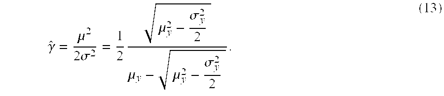
- the mean and the variance of the variables x I 2 and x Q 2 considered as one and the same random variable can also be estimated.
- ⁇ being the mean common to the variables X I and X Q and ⁇ 2 the variance of these variables X I and X Q .
- the invention also provides a method of determining the power assigned to a transmitter in which the power is determined in a manner such that, in the receiver, the signal to noise ratio is always at least equal to a reference value, which is characterised in that the signal to noise ratio of the receiver is estimated according to the method described above.
- the invention also makes provision for applying the latter method of determining power assigned to a transmitter to a telecommunications system in which the transmitter and the receiver communicate by means of retransmission means on board an orbiting satellite.
- FIG. 1 is a diagram of a satellite telecommunications system to which the invention applies
- FIG. 2 is a diagram of a code separation device, known per se,
- FIG. 3 is a diagram showing the noise estimation principle in accordance with the invention.
- FIGS. 4 and 5 are diagrams showing embodiments of the method in accordance with the invention.
- FIG. 1 The example which will now be described in connection with the figures relates to a telecommunication system in which the surface of the earth is divided into zones 10 (FIG. 1) , only one of which has been depicted in the figure.
- zones 10 In each zone there is found, on the one hand, a central control or connection station 20 , and, on the other hand, terminals or subscriber sets 16 , 18 , etc.
- the terminals 16 , 18 , etc. communicate with one another by means of retransmission equipment on board a satellite 14 in low or medium orbit.
- the altitude of the satellite is around 1,500 km.
- This satellite 14 moves in an orbit 12 in which there are other satellites.
- a number of orbits 12 are provided.
- the equipment in the next satellite (not shown), for example in the same orbit 12 , takes over the communication.
- the word “satellite” will sometimes be used for the equipment on board thereof.
- the control and connection station 20 provides the management of the communications between the terminals 16 , 18 , etc. In particular, it allocates frequency, power and code resources for each of the terminals. To that end, this station 20 communicates with each of the terminals, also by means of the satellite 14 .
- the inter-terminal communications are performed by means of the station 20 .
- the terminal 16 communicates with the terminal 18
- the terminal 16 sends the data to the station 20 by means of the satellite and the station 20 retransmits these data to the terminal 18 , also by means of the satellite.
- the station 20 is connected to a terrestrial network 22 , of the ATM type in the example.
- this station 20 is connected, by means of an ATM switch 34 , to a broadband network 36 , to a narrow-band network 38 , and to servers 28 .
- the narrow-band network 38 allows the connection of users 30 and servers 24 .
- the broadband network 36 allows the connection of users 32 and servers 26 .
- Such a telecommunication system of the asynchronous transmission type allows a high data rate with a large capacity and a small delay due to the transmission.
- the data are in digital form and organized in packets or cells comprising, for the ATM standard, 384 data bits (or symbols) and 40 header bits (or symbols).
- the problem which the invention aims to solve is to allocate, to each communication, from the control station 20 to a terminal 16 , 18 and from a terminal 16 , 18 to the control station, a power resource which is such that this power is that just necessary for the signal to noise ratio to meet the specifications.
- the communications will have a required quality of service guaranteeing a bit error rate lower than a predetermined limit without excessive power consumption. This is because the transmitted power must be that which is just necessary, since the power available in the satellite is limited and, if a communication requires more power, that excess comes by reducing the power allocated to the other communications.
- terminals being mass-marketed devices whose price must be as low as possible, it is preferable that their power is limited.
- the signal to noise ratio is determined at reception and the transmission power is adjusted so that this signal to noise ratio is equal to a reference value.
- the invention concerns more precisely the estimation of the noise and the estimation of,the signal to noise ratio.
- the adjustment of the transmission power, and therefore the estimation of the signal to noise ratio has a particular importance, since the power received by the receivers can vary to a great extent, notably because of variations in the propagation conditions due to random changes in the meteorological conditions.
- the propagation is degraded substantially in the event of rain compared with clear weather.
- the propagation is also degraded as a result of jitter and maskings.
- the propagation conditions can also introduce noise and the noise source can, itself, have characteristics which vary.
- the causes of noise are, notably, interference due to the use of the same transmission frequencies for neighbouring zones, or jamming by other transmission systems.
- a noise estimation method is provided which is particularly accurate where the cells are assigned codes such as orthogonal codes.
- C i represents a code and cell i represents a cell.
- the number of codes is equal to 80.
- the device depicted in FIG. 2 which comprises multipliers 42 1 , 42 2 , . . . , 42 80 , each of which has a first input receiving the signal S and a second input to which a code C 1 , C 2 , . . . or C 80 is applied.
- the cell cell i is obtained as a result of the orthogonality properties of the codes, that is to say:
- each signal receiver or terminal receives all the M codes which are transmitted at a given moment.
- the invention consists of taking advantage of this simultaneous reception of M codes to significantly reduce the noise estimation variance. This is because it can be shown that the observed noise contributions for each code are uncorrelated although coming from the same random process.
- an estimation of the noise is performed on all the received cells, that is to say the noise powers for each code are summed and the arithmetic mean of the noise powers is worked out. It is this mean which is used for the estimation of the signal to noise ratio for a cell. It can thus be seen in FIG. 3 that the transmitter 50 assigns, to each of the transmitted cells, a code, all the codes being orthogonal. This code assignment is referred to as spreading (block 52 ).
- the M cells assigned codes, respectively 1 to M, are transmitted by a channel 54 (radio transmission) which is a source of noise.
- a sequence of unspreading 58 is performed as depicted in FIG. 2 and the noise power is determined for each cell (block 60 1 to 60 M ) . These noise power estimates are added up, and then the sum is divided by M. In FIG. 3, this operation is performed by the mean block 62 . The result is the noise ⁇ circumflex over ( ⁇ ) ⁇ 2 which is used for estimating the signal to noise ratio for each cell.
- the noise power estimation is performed by determining the variance of the received signals.
- the signal to noise ratio is obtained by estimating, in addition, the mean of the signals.
- the noise measurement can be used for the subsequent estimation of the noise of signals intended for the receiver.
- the transmitted signals are phase modulated with two or four states.
- phase between these two signals can take 4 values, for example ⁇ /4, 3 ⁇ /4, 5 ⁇ /4 and 7 ⁇ /4 and each of these phase differences represents a pair of binary numbers 00, 01, 10 or 11.
- phase can take only two values representing a “0” and a “1”, respectively.
- a phase-modulated signal is represented by a complex signal X(N) which can be represented by two real signals X I (N) and X Q (N) which are the projections of the complex signal along the axes, respectively I and Q.
- the signals X I (N) and X Q (N) correspond to Gaussian random variables of means ⁇ I and ⁇ Q and variance ⁇ 2 .
- the random variable Y(N) such that:
- the variables X I (N) 2 and X Q (N) 2 being Gaussian random variables of mean different from zero, the random variable Y(N) follows a non-symmetrical ⁇ 2 law with two degrees of freedom.
- the signal to noise ratio of the phase-modulated signal can be determined by estimating the mean and the variance of Y(N). To that end, the following relationships are used:
- the signals X I (N) and X Q (N) are considered as constituting one and the same random variable which can be written as a vector Y(N) with two components X I (N) 2 and X Q (N) 2 :
- ⁇ is the mean common to the two variables X I and X Q .
- FIG. 4 depicts the various steps of the method where the variable y is the sum of the squares of x I and x Q .
- the block 70 corresponds to the demodulated signal in a specific code j.
- this signal is squared. From this squared signal, the mean and the variance of the signal y are estimated (block 74 ). For this code j, the mean and the variance, that is to say the numerator (block 76 ) and the denominator (block 78 ) of the formula (9) above, are calculated. The variance is determined as indicated above in connection with FIG. 3, that is to say by working out the mean of the sum of the individual variances for each of the codes (block 80 ).
- the signal to noise ratio is estimated by using, in the block 82 , the ratio of the mean value provided by the block 76 to four times the variance ⁇ circumflex over ( ⁇ ) ⁇ 2 provided by the block 80 .
- the method of estimating the noise power of a signal assigned a code can be used independently of the method of estimating the signal to noise ratio which was described above for a phase-modulated signal.
- the method of estimating the signal to noise ratio of the prior art which was described above in the introduction to the description, could be resorted to.
- this method is not limited to a phase modulation.
- the method of estimating the signal to noise ratio for phase-modulated digital signals can be used independently of the method of estimating the noise power which was described in connection with FIG. 3 .
Abstract
Description


Claims (12)
Applications Claiming Priority (2)
| Application Number | Priority Date | Filing Date | Title |
|---|---|---|---|
| FR9901295A FR2789534B1 (en) | 1999-02-04 | 1999-02-04 | METHOD OF ESTIMATING THE SIGNAL TO NOISE RATIO OF A DIGITAL SIGNAL RECEIVED BY A RADIO COMMUNICATION RECEIVER |
| FR9901295 | 1999-02-04 |
Publications (1)
| Publication Number | Publication Date |
|---|---|
| US6539214B1 true US6539214B1 (en) | 2003-03-25 |
Family
ID=9541596
Family Applications (1)
| Application Number | Title | Priority Date | Filing Date |
|---|---|---|---|
| US09/393,458 Expired - Fee Related US6539214B1 (en) | 1999-02-04 | 1999-09-10 | Method of estimating the signal to noise ratio of a digital signal received by a radiocommunications receiver |
Country Status (12)
| Country | Link |
|---|---|
| US (1) | US6539214B1 (en) |
| EP (1) | EP1026843B1 (en) |
| JP (1) | JP4521913B2 (en) |
| KR (1) | KR20000076605A (en) |
| CN (1) | CN1263387A (en) |
| AT (1) | ATE218019T1 (en) |
| AU (1) | AU1357600A (en) |
| BR (1) | BR0000220A (en) |
| DE (1) | DE69901532T2 (en) |
| FR (1) | FR2789534B1 (en) |
| ID (1) | ID24780A (en) |
| TW (1) | TW453053B (en) |
Cited By (4)
| Publication number | Priority date | Publication date | Assignee | Title |
|---|---|---|---|---|
| US20040131028A1 (en) * | 2002-07-23 | 2004-07-08 | Schiff Leonard N. | Noise compensation in satellite communications |
| US20040244050A1 (en) * | 2003-05-27 | 2004-12-02 | Kim Dong-Won | Method and apparatus providing channel management in a multi-frequency network broadcasting system |
| US6871066B1 (en) * | 1999-09-17 | 2005-03-22 | Telefonaktiebolaget Lm Ericsson (Publ) | Method and an apparatus for estimating residual noise in a signal and an apparatus utilizing the method |
| US20070207741A1 (en) * | 2003-08-07 | 2007-09-06 | Jones Alan E | Method and arrangement for noise variance and sir estimation |
Families Citing this family (4)
| Publication number | Priority date | Publication date | Assignee | Title |
|---|---|---|---|---|
| FR2789534B1 (en) * | 1999-02-04 | 2001-06-08 | Cit Alcatel | METHOD OF ESTIMATING THE SIGNAL TO NOISE RATIO OF A DIGITAL SIGNAL RECEIVED BY A RADIO COMMUNICATION RECEIVER |
| KR20030085745A (en) * | 2002-05-01 | 2003-11-07 | 엘지전자 주식회사 | Interference power estimation method in mobile telecommunication system |
| CN100448183C (en) * | 2004-06-07 | 2008-12-31 | 东南大学 | Online S/N ratio estimation of calibrated average for Rayleigh channel |
| CN101640572B (en) * | 2008-07-18 | 2015-01-28 | 美满电子科技(上海)有限公司 | Method and apparatus for signal/noise ratio measurement and communication equipment |
Citations (11)
| Publication number | Priority date | Publication date | Assignee | Title |
|---|---|---|---|---|
| US5317599A (en) | 1992-01-14 | 1994-05-31 | Nec Corporation | Method and circuit for detecting CN ratio of QPSK signal |
| US5418849A (en) * | 1988-12-21 | 1995-05-23 | Siemens Telecomunicazioni S.P.A. | Procedure and device for adaptive digital cancellation of the echo generated in telephone connections with time-variant characteristics |
| US5463662A (en) * | 1994-04-08 | 1995-10-31 | Echelon Corporation | Apparatus and method for reducing errors in data caused by noise through use of blanking |
| US5506869A (en) | 1994-10-27 | 1996-04-09 | Northern Telecom Limited | Methods and apparatus for estimating carrier-to-interference ratios at cellular radio base stations |
| US5799005A (en) * | 1996-04-30 | 1998-08-25 | Qualcomm Incorporated | System and method for determining received pilot power and path loss in a CDMA communication system |
| US5842114A (en) * | 1997-02-12 | 1998-11-24 | Interdigital Technology Corporation | Global channel power control to minimize spillover in a wireless communication environment |
| US5974098A (en) * | 1994-09-12 | 1999-10-26 | Nec Corporation | Received signal detector for digital demodulator |
| US5978657A (en) * | 1995-01-19 | 1999-11-02 | Sony Corporation | Method of and apparatus for acquiring strength information from received signals transmitted by a plurality of base stations and for transmitting a signal thereof |
| US6104933A (en) * | 1997-06-23 | 2000-08-15 | Telefonaktiebolaget Lm Ericsson | Method and apparatus for control of base stations in macro diversity radio systems |
| US6118767A (en) * | 1997-11-19 | 2000-09-12 | Metawave Communications Corporation | Interference control for CDMA networks using a plurality of narrow antenna beams and an estimation of the number of users/remote signals present |
| US6122260A (en) * | 1996-12-16 | 2000-09-19 | Civil Telecommunications, Inc. | Smart antenna CDMA wireless communication system |
Family Cites Families (5)
| Publication number | Priority date | Publication date | Assignee | Title |
|---|---|---|---|---|
| US5297161A (en) * | 1992-06-29 | 1994-03-22 | Motorola Inc. | Method and apparatus for power estimation in an orthogonal coded communication system |
| JP3457357B2 (en) * | 1993-07-23 | 2003-10-14 | 株式会社日立製作所 | Spread spectrum communication system, transmission power control method, mobile terminal device, and base station |
| JPH10108249A (en) * | 1996-09-26 | 1998-04-24 | Nippon Telegr & Teleph Corp <Ntt> | System and method for controlling transmission power |
| JPH10190497A (en) * | 1996-12-27 | 1998-07-21 | Fujitsu Ltd | Sir measuring device |
| FR2789534B1 (en) * | 1999-02-04 | 2001-06-08 | Cit Alcatel | METHOD OF ESTIMATING THE SIGNAL TO NOISE RATIO OF A DIGITAL SIGNAL RECEIVED BY A RADIO COMMUNICATION RECEIVER |
-
1999
- 1999-02-04 FR FR9901295A patent/FR2789534B1/en not_active Expired - Fee Related
- 1999-08-26 DE DE69901532T patent/DE69901532T2/en not_active Expired - Lifetime
- 1999-08-26 EP EP99402123A patent/EP1026843B1/en not_active Expired - Lifetime
- 1999-08-26 AT AT99402123T patent/ATE218019T1/en not_active IP Right Cessation
- 1999-09-10 US US09/393,458 patent/US6539214B1/en not_active Expired - Fee Related
-
2000
- 2000-01-17 JP JP2000007428A patent/JP4521913B2/en not_active Expired - Fee Related
- 2000-01-21 TW TW089101013A patent/TW453053B/en active
- 2000-01-25 AU AU13576/00A patent/AU1357600A/en not_active Abandoned
- 2000-01-28 BR BR0000220-8A patent/BR0000220A/en not_active Application Discontinuation
- 2000-02-01 ID IDP20000071A patent/ID24780A/en unknown
- 2000-02-03 KR KR1020000005427A patent/KR20000076605A/en not_active Application Discontinuation
- 2000-02-04 CN CN00101993A patent/CN1263387A/en active Pending
Patent Citations (11)
| Publication number | Priority date | Publication date | Assignee | Title |
|---|---|---|---|---|
| US5418849A (en) * | 1988-12-21 | 1995-05-23 | Siemens Telecomunicazioni S.P.A. | Procedure and device for adaptive digital cancellation of the echo generated in telephone connections with time-variant characteristics |
| US5317599A (en) | 1992-01-14 | 1994-05-31 | Nec Corporation | Method and circuit for detecting CN ratio of QPSK signal |
| US5463662A (en) * | 1994-04-08 | 1995-10-31 | Echelon Corporation | Apparatus and method for reducing errors in data caused by noise through use of blanking |
| US5974098A (en) * | 1994-09-12 | 1999-10-26 | Nec Corporation | Received signal detector for digital demodulator |
| US5506869A (en) | 1994-10-27 | 1996-04-09 | Northern Telecom Limited | Methods and apparatus for estimating carrier-to-interference ratios at cellular radio base stations |
| US5978657A (en) * | 1995-01-19 | 1999-11-02 | Sony Corporation | Method of and apparatus for acquiring strength information from received signals transmitted by a plurality of base stations and for transmitting a signal thereof |
| US5799005A (en) * | 1996-04-30 | 1998-08-25 | Qualcomm Incorporated | System and method for determining received pilot power and path loss in a CDMA communication system |
| US6122260A (en) * | 1996-12-16 | 2000-09-19 | Civil Telecommunications, Inc. | Smart antenna CDMA wireless communication system |
| US5842114A (en) * | 1997-02-12 | 1998-11-24 | Interdigital Technology Corporation | Global channel power control to minimize spillover in a wireless communication environment |
| US6104933A (en) * | 1997-06-23 | 2000-08-15 | Telefonaktiebolaget Lm Ericsson | Method and apparatus for control of base stations in macro diversity radio systems |
| US6118767A (en) * | 1997-11-19 | 2000-09-12 | Metawave Communications Corporation | Interference control for CDMA networks using a plurality of narrow antenna beams and an estimation of the number of users/remote signals present |
Cited By (7)
| Publication number | Priority date | Publication date | Assignee | Title |
|---|---|---|---|---|
| US6871066B1 (en) * | 1999-09-17 | 2005-03-22 | Telefonaktiebolaget Lm Ericsson (Publ) | Method and an apparatus for estimating residual noise in a signal and an apparatus utilizing the method |
| US20040131028A1 (en) * | 2002-07-23 | 2004-07-08 | Schiff Leonard N. | Noise compensation in satellite communications |
| US8121536B2 (en) * | 2002-07-23 | 2012-02-21 | Qualcomm Incorporated | Noise compensation in satellite communications |
| US20040244050A1 (en) * | 2003-05-27 | 2004-12-02 | Kim Dong-Won | Method and apparatus providing channel management in a multi-frequency network broadcasting system |
| US7865930B2 (en) * | 2003-05-27 | 2011-01-04 | Samsung Electronics Co., Ltd | Method and apparatus providing channel management in a multi-frequency network broadcasting system |
| US20070207741A1 (en) * | 2003-08-07 | 2007-09-06 | Jones Alan E | Method and arrangement for noise variance and sir estimation |
| US7590388B2 (en) * | 2003-08-07 | 2009-09-15 | Ipwireless, Inc. | Method and arrangement for noise variance and SIR estimation |
Also Published As
| Publication number | Publication date |
|---|---|
| ATE218019T1 (en) | 2002-06-15 |
| EP1026843A1 (en) | 2000-08-09 |
| TW453053B (en) | 2001-09-01 |
| CN1263387A (en) | 2000-08-16 |
| JP2000295140A (en) | 2000-10-20 |
| KR20000076605A (en) | 2000-12-26 |
| ID24780A (en) | 2000-08-10 |
| DE69901532D1 (en) | 2002-06-27 |
| BR0000220A (en) | 2000-12-05 |
| DE69901532T2 (en) | 2003-01-09 |
| FR2789534B1 (en) | 2001-06-08 |
| AU1357600A (en) | 2000-08-10 |
| EP1026843B1 (en) | 2002-05-22 |
| JP4521913B2 (en) | 2010-08-11 |
| FR2789534A1 (en) | 2000-08-11 |
Similar Documents
| Publication | Publication Date | Title |
|---|---|---|
| US7392018B1 (en) | Channel estimation applique for wireless communications | |
| CN100401645C (en) | MMSE reception of DS-CDMA with transmit diversity | |
| CN101814931B (en) | Doppler frequency shift estimation and compensation method in TD-SCDMA (Time Division-Synchronization Code Division Multiple Access) system | |
| US7398056B1 (en) | Channel estimation applique for multiple antenna wireless communications | |
| US20030153273A1 (en) | Vector network analyzer applique for adaptive communications in wireless networks | |
| CN100568784C (en) | Utilize multi-slot average interpolation to carry out the method and system of channel estimating | |
| EP0707389A2 (en) | Apparatus for and method of broadcast satellite network return-link signal transmission | |
| KR100744456B1 (en) | M-ary orthogonal/balanced uwb-transmitted reference system | |
| US6885655B2 (en) | Noise characterization in a wireless communication system | |
| US6539214B1 (en) | Method of estimating the signal to noise ratio of a digital signal received by a radiocommunications receiver | |
| US7577190B2 (en) | Method for prediction of a channel coefficient | |
| Bello | Error probabilities due to atmospheric noise and flat fading in HF ionospheric communication systems | |
| Azzahra | NOMA signal transmission over millimeter-wave frequency for backbone network in HAPS with MIMO antenna | |
| Vilnrotter et al. | Telecommand/telemetry ranging for deep-space applications | |
| CN100449968C (en) | Method and apparatus for monitoring a reductant (standby) transmitter in a radio communication system | |
| US6987796B1 (en) | Method for receiving spectrum spread signals with frequency offset correction | |
| US7042966B1 (en) | Method of estimating the signal-to-noise ratio in a telecommunications receiver and an application of the method to controlling a transmitter | |
| US20020169006A1 (en) | Cellular communications system and related methods | |
| MXPA00001074A (en) | Method of estimating the signal to noise ratio of a digital signal | |
| RU2289148C1 (en) | Signal detector | |
| Divsalar et al. | Diversity Techniques for Multipath Fading Channels between Earth and the Moon | |
| Loo et al. | Performance analysis and measurement of a saw‐based group demodulator for on‐board processing in communications satellites | |
| Kostic | Error rates of DCPSK signlas in hard-limited multilink systems with cochannel interference and noise | |
| JPS6343936B2 (en) | ||
| JPS6343934B2 (en) |
Legal Events
| Date | Code | Title | Description |
|---|---|---|---|
| AS | Assignment |
Owner name: ALCATEL, FRANCE Free format text: ASSIGNMENT OF ASSIGNORS INTEREST;ASSIGNORS:LAPAILLE, CEDRIC;CALOT, GUILLAUME;REEL/FRAME:010319/0782;SIGNING DATES FROM 19990901 TO 19990909 |
|
| FEPP | Fee payment procedure |
Free format text: PAYOR NUMBER ASSIGNED (ORIGINAL EVENT CODE: ASPN); ENTITY STATUS OF PATENT OWNER: LARGE ENTITY |
|
| FPAY | Fee payment |
Year of fee payment: 4 |
|
| AS | Assignment |
Owner name: SUTTON WIRELESS, L.L.C., DELAWARE Free format text: ASSIGNMENT OF ASSIGNORS INTEREST;ASSIGNOR:ALCATEL LUCENT;REEL/FRAME:019094/0733 Effective date: 20070223 |
|
| AS | Assignment |
Owner name: ALCATEL LUCENT, FRANCE Free format text: CHANGE OF NAME;ASSIGNOR:ALCATEL;REEL/FRAME:019297/0420 Effective date: 20061130 |
|
| FEPP | Fee payment procedure |
Free format text: PAYOR NUMBER ASSIGNED (ORIGINAL EVENT CODE: ASPN); ENTITY STATUS OF PATENT OWNER: LARGE ENTITY Free format text: PAYER NUMBER DE-ASSIGNED (ORIGINAL EVENT CODE: RMPN); ENTITY STATUS OF PATENT OWNER: LARGE ENTITY |
|
| FPAY | Fee payment |
Year of fee payment: 8 |
|
| REMI | Maintenance fee reminder mailed | ||
| LAPS | Lapse for failure to pay maintenance fees | ||
| STCH | Information on status: patent discontinuation |
Free format text: PATENT EXPIRED DUE TO NONPAYMENT OF MAINTENANCE FEES UNDER 37 CFR 1.362 |
|
| FP | Lapsed due to failure to pay maintenance fee |
Effective date: 20150325 |