US6542756B1 - Method for detecting forward link power control bits in a communication system - Google Patents
Method for detecting forward link power control bits in a communication system Download PDFInfo
- Publication number
- US6542756B1 US6542756B1 US09/515,023 US51502300A US6542756B1 US 6542756 B1 US6542756 B1 US 6542756B1 US 51502300 A US51502300 A US 51502300A US 6542756 B1 US6542756 B1 US 6542756B1
- Authority
- US
- United States
- Prior art keywords
- power control
- phase
- result
- quadrature
- summing
- Prior art date
- Legal status (The legal status is an assumption and is not a legal conclusion. Google has not performed a legal analysis and makes no representation as to the accuracy of the status listed.)
- Expired - Lifetime
Links
Images

Classifications
-
- H—ELECTRICITY
- H04—ELECTRIC COMMUNICATION TECHNIQUE
- H04W—WIRELESS COMMUNICATION NETWORKS
- H04W52/00—Power management, e.g. TPC [Transmission Power Control], power saving or power classes
- H04W52/04—TPC
- H04W52/54—Signalisation aspects of the TPC commands, e.g. frame structure
- H04W52/58—Format of the TPC bits
-
- H—ELECTRICITY
- H04—ELECTRIC COMMUNICATION TECHNIQUE
- H04W—WIRELESS COMMUNICATION NETWORKS
- H04W52/00—Power management, e.g. TPC [Transmission Power Control], power saving or power classes
- H04W52/04—TPC
- H04W52/06—TPC algorithms
- H04W52/08—Closed loop power control
Definitions
- the invention relates generally to wireless communication systems and, more particularly, to a method for detecting forward link power control bits in a code division multiple access (CDMA) communication system.
- CDMA code division multiple access
- the IS-95 CDMA system is unique in that its forward and reverse links have different link structures.
- the forward link is made up of four types of logical channels: pilot, sync, paging, and traffic channels.
- the pilot channel is transmitted continuously by the base station to provide the mobile station with timing and phase reference.
- the reverse link is made up of two types of logical channels: access and traffic channels. The reason that a pilot channel is not used on the reverse link is that it has been heretofore impractical for each mobile station to broadcast its own pilot sequence. For this reason, a reverse pilot channel has not been suggested in IS-95.
- the recently announced CDMA 2000 system includes a continuous Reverse Pilot Channel (R-PICH) and a Reverse Fundamental Channel (R-FCH), one or more Reverse Supplemental Channels (R-SCH), and a Reverse Dedicated Control Channel (R-DCCH).
- R-PICH is made up of a fixed reference value and multiplexed forward Power-Control (PC) information.
- PC power-Control
- the base station processes the Reverse Pilot Channel (R-PICH) to determine whether a +1 or a ⁇ 1 was sent at each 1.25 ms power-control group (PCG).
- each power control group presents a challenge, however, in that channel imperfections and multipath effects can result in a receiver mistakenly detecting the received power control bit which may negatively impact system operation by causing forward link channels to transmit at inappropriate power levels.
- a method to better estimate the value of a power control bit at a receiver to better control forward link power levels is a challenge, however, in that channel imperfections and multipath effects can result in a receiver mistakenly detecting the received power control bit which may negatively impact system operation by causing forward link channels to transmit at inappropriate power levels.
- the present invention provides a novel and improved method for detecting forward link power control bits by a base station from a reverse link signal.
- the base station establishes communications on both the forward and reverse link with an SU. Communications are transmitted to the SU on the forward link and communications are received from the SU on the reverse link.
- the SU commands the base station to incrementally alter the forward link transmit power.
- the SU performs such a task by sending periodic power control bits to the base station on a reverse link signal.
- the transmitted power control bits may be distorted by channel imperfections and multipath effects.
- the present invention derives an optimum decision variable for performing power control bit estimation at the base station.
- the optimum decision variable for determining the sign of a received power control bit is computed by considering the in-phase and quadrature-phase components of a single power control group received on the reverse pilot channel.
- Both the in-phase and quadrature-phase components of the power control group are respectively made up of a pilot part containing the reverse pilot signal which is repeated over a 1152 ⁇ N chip duration, where N is the spreading rate, and a power control part containing the forward power control bit, which is repeated over a 384 ⁇ N chip duration.
- the optimum decision variable is obtained by first multiplying the pilot part (e.g., 1152 ⁇ N) by the power control part (e.g., 384 ⁇ N) for the respective in-phase and quadrature components to obtain an in-phase and quadrature result and summing the two intermediate results to obtain a final value, whose sign provides an estimation regarding whether a +1 or ⁇ 1 power control bit was sent by the SU.
- the present invention performs the method described above to include the different multipath components by using a rake receiver and summing the individual results of each finger to derive a better overall estimate of the transmitted power control bit.
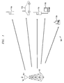
- FIG. 1 is a diagram illustrating a wireless communication system implemented according to one embodiment of the present invention in which reverse link power control commands issued by mobile stations are received and implemented by a servicing base station;
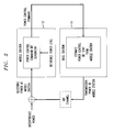
- FIG. 2 is a block diagram of a reverse power control.loop used in a CDMA 2000 system
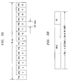
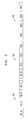
- FIG. 3 a is a diagram illustrating a single frame of a reverse pilot channel according to the present invention comprising 16 power control groups;
- FIG. 3 b is a diagram of a single power control group of FIG. 3 a;
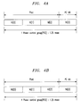
- FIG. 4 a is a diagram of the in-phase component of a single power control group after being received over a fading channel after complex despreading
- FIG. 4 b is a diagram of the quadrature-phase component of a single power control group after being received over a fading channel after complex despreading
- FIG. 5 is a diagram of three power control groups received in consecutive order.
- FIG. 1 is a schematic diagram illustrating a wireless communication system, designated generally by reference numeral 100 and implemented according to the present invention in which forward link power control bits are detected at the base station 102 .
- the base station 102 operates according to the code division multiple access (CDMA) protocol as per ANSI 2000 standard.
- CDMA code division multiple access
- SUs subscribing units
- the base station 102 and the SUs may operate according to various other communication protocols.
- the base station 102 and the SUs 110 a - 110 d may operate according to multiple communication protocols.
- the TIA/EIA/IS-95 standard of performing power control in a CDMA communication system generally divides power control into two general categories: forward power control and reverse power control. There are three components of reverse power control: open loop, closed loop and outer loop.
- Open loop power control sets the transmit power based upon the power that is received at the mobile station. Open loop power control compensates for the path loss from the mobile station to the base station and handles very slow fading. Closed loop power control includes an 800 bps feedback loop from the base station to the mobile station to set the transmit power of the mobile station. Closed loop power control compensates for medium to fast fading and for inaccuracies in open loop power control.
- Outer loop power control is implementation specific but typically adjusts the closed loop power control threshold in the base station in order to maintain a desired frame error rate.
- the later standard i.e., TIA/EIA/IS-2000, provides for an additional form of forward power control where power control information is multiplexed on the reverse pilot channel (R-PICH).
- R-PICH reverse pilot channel
- the time multiplexed forward power control information is referred to as the power control sub-channel; the details of which are described below with reference to FIG. 2 .
- FIG. 2 there is shown a block diagram of a forward power control loop used in TIA/EIA/2000.
- An SU receives a signal transmitted from a base station on a forward link, compares it with an internally generated reference value, and generates forward-link power control bits to be carried on an R-PICH as reverse power sub-channel.
- forward link power control bits are time-multiplexed in the last quarter of each 20 ms frame of the reverse pilot channel.
- FIG. 3 a illustrates a 20 ms frame structure for a reverse pilot channel divided into 16 segments, where each individual segment is known in the art as a power control group having a duration of 1.25 msec (20 ms/16 segments).
- FIG. 3 b illustrates a single power control group of FIG. 1 .
- the power control group is shown divided into four sections of equal length.
- the first three quarters of the power control group contain a repeated sequence of pilot symbols having a fixed value equal to the value of the PN code of the reverse link.
- the last quarter contains a repeated sequence of power control symbols having a fixed value equal to the value of the power control bit (PCB) transmitted in that particular transmission interval.
- PCB power control bit
- the reverse power sub-channel provides information on the quality of the forward link at the rate of 1 bit per Power Control Group, (1 bit/1.25 ms), and is used by the forward link channels to adjust their power.
- the amount of mobile power increase and power decrease per each PCB is nominally +1 dB and ⁇ 1 dB, respectively, however the TIA/EIA/IS-2000 standard provides for 0.5 dB and 0.25 dB respective increments.
- the present embodiment describes the method of the present invention for a reverse pilot channel having a spreading rate of 3. It is contemplated by the present invention that spreading rates other than 3 may be used. In a preferred embodiment, for a spreading rate of 3, a single power control group would include 4608 chips (384 ⁇ 4 groups ⁇ spreading rate of 3).
- FIG. 3 b illustrates a single power control group having a spreading rate of 3, including 4608 chips divided into 4 sections of 1152 chips, where the 1152 chips in each of the first three sections transmit the pilot signal (+1), and the 1152 chips in the final section (i.e., last quarter) transmit the reverse power sub-channel information.
- the reverse power sub-channel information transmitted in the last quarter of the frame is transmitted as 1152 chips, where each chip has a constant value over the 1152 chip duration of either +1 or ⁇ 1, where a +1 value corresponds to a power control bit of “0” and thus an increase in power, and a ⁇ 1 value corresponds to a power control bit of “1” and thus a decrease in power.
- FIGS. 4 a and 4 b illustrate a single power control group of the complex reverse pilot signal (R-PICH) after being multiplied by respective I and Q PN sequences at the receiver.
- the complex reverse pilot signal is used by the mobile station for initial acquisition, time tracking, Rake-receiver coherent reference recovery and power-control measurements. It is a complex channel having in-phase (I) and quadrature (Q) components.
- FIGS. 4 a and 4 b illustrate the respective I and Q components of the complex reverse pilot signal, where hI( 0 ) represents the accumulation of the first 1152 chips (i.e., first section) of the power control, and hI( 1 ) represents the accumulation of the next 1152 chips (i.e., second section) of the power control group. Accordingly, hI( 2 ) and hI( 3 ) represent the respective accumulation of the third and fourth sections of the power control group.
- FIG. 4 b illustrates a similar result for the quadrature channel component of the power control group
- the respective probability density functions of hI( 3 ) and hQ( 3 ) are determined, where hI( 3 ) and hQ( 3 ) are random variables.
- hI( 3 ) and hQ( 3 ) are random variables.
- obtaining the probability density function for random variables is not possible, however, in a special case, if the mean and variance of the gaussian random variables can be determined, the probability density function is attainable. It must therefore be shown that the random variables hI( 3 ) and hQ( 3 ) are gaussian random variables.
- hI( 3 ) and hQ( 3 ) are derived below.
- the following definitions are provided to assist in the understanding of their derivation. Further, the derivation assumes that ⁇ and ⁇ are constant over a power control group. It is further assumed that timing recovery is within a pre-specified tolerance.
- ⁇ fading envelope, assumed to be constant over a power control group
- ⁇ the combined effect of Doppler frequent shift and frequency offsets, assumed to be constant over a power control group.
- nI, nQ complex channel noise plus quantization noise after the automatic gain control block.
- A pilot signal amplitude
- r(i) 4 bits complex signal after automatic gain control.
- the pilot signal p(i) transmitted at the mobile station is
- the phase of the pilot signal is rotated by 180° at the power control bit location.
- the received pilot signal r(i) is defined as
- Input signal power is 2A 2 ⁇ 2 and noise power is E[nI 2 ]+E[nQ 2 ], where E[.] represent the expected value.
- the received signal can be assumed to have Gaussian statistics by applying the principles of the Central Limit Theorem which is well known in the art. Considering that the noise power is a lot larger than the signal power of the received signal, the statistics of the received signal are assumed to be that of the noise. Further, because the I-channel and Q-channel are mutually orthogonal communication media, it can be assumed that the I-channel noise and Q-channel noise are iid (independent and identically distributed) gaussian random variables with zero means. Then ⁇ 2 is defined as the variance of nI and nQ. At a normal operating point, the input SNR is ⁇ 30 dB. Considering that the variance of the I-channel and Q-channel AGC outputs are constant (defined as C AGC ) and that the noise power is much larger than the signal power, ⁇ 2 is derived in equation (5) as
- Equation (6) illustrates the process of complex despreading whereby a complex received signal r(i) multiplied by an in-phase PN code, PNI(i) and a quadrature-phase PN code, respectively with the resulting product terms being summed over M, where M is the coherent integration length of a quarter power control group.
- M is the coherent integration length of a quarter power control group.
- sampling period is a chip duration
- ⁇ I and ⁇ Q are mutually independent random variables with the same statistics.
- hI(l) are Gaussian random variables with mean 2MA ⁇ cos ⁇ and variance 2M ⁇ 2
- hQ(l) are Gaussian random variables with mean 2MA ⁇ sin ⁇ and variance 2M ⁇ 2 .
- hI(l) and hQ(l) are Gaussian random variables with mean 2MA ⁇ sin ⁇ and variance 2M ⁇ 2 .
- the probability density function is then used to derive an optimum decision criteria using maximum a posteriori estimation, as will be defined below.
- hI( 3 ) and hQ( 3 ) contain the power control information in each power control group (i.e., the accumulated 1152 chips in the fourth section of the power control group.
- X and Y may be derived in a number of ways in alternate embodiments, however, in the preferred embodiment (X,Y) is derived as
- FIG. 5 illustrates three consecutively transmitted power control groups transmitted from the mobile station, where the Power Control Group, generally designated as 503 is considered the power control group currently being received by the base station.
- a better estimate of X and Y may be obtained by considering the subsequently received power control group 505 in combination with the current power control group 503 to form a better estimate of X and Y. It should be noted that the better estimate comes at the additional cost of estimation delay. That is, an optimum decision cannot be made until both power control groups 503 and 505 are processed, as defined by equation (10).
- Equation (10) illustrates that by using the first 3 ⁇ 4 of power control group 505 in combination with power control group 503 , a better estimate of X and Y may be obtained.
- equation (11) is not subject to the estimation delay drawback defined by equation (10), as a consequence of using a previously received power control group 501 .
- x is the observed result from accumulating the first 3456 chips of the I component of the power control group.
- y is the observed result from accumulating the first 3456 chips for the Q component of the power control group.
- u represents the accumulation of the last 1152 chips of the I component of the power control group, containing the power control information.
- v represents the accumulation of the last 1152 chips of the Q component of the power control group, containing the power control information.
- equation (12) the derivation of the optimum decision criteria begins with equation (12), defined as:
- Equation (13) defines two conditional probabilities, where the first conditional probability is the probability of a power control bit being equal to +1 given the occurrence of events T 1 and T 2 .
- the second conditional probability is the probability of a power control bit being equal to ⁇ 1 given the occurrence of events T 1 and T 2 .
- T1 , PC ⁇ ⁇ bit - 1 ] P ⁇ [ T1
- the first comparison of equation (14) states on the left-hand side that the conditional probability of receiving a PC bit value of +1 given events T 1 and T 2 , and the right hand side states that the conditional probability of receiving a ⁇ 1 value given events T 1 and T 2 .
- the first comparison is not in a form that is amenable to determining the probability density functions.
- the subsequent comparisons of equation (14) utilize the Bayesian rule to re-arrange equation (14) to a form which lends itself more readily to deriving the probability density functions.
- T 1 , PC bit +1] and P[T 2
- T 2 is a gaussian random variable with known mean and variance. It is apparent that event T 2 is equivalent to events (U,V), and given that (U,V) have been proven to be gaussian random variables with a known variance, it therefore follows that event T 2 is a gaussian random variable. Further, it is assumed that the mean of T 2 is equal to the observed value of T 1 because T 1 is more reliable event.
- T 1 is more reliable than T 2 as it represents the accumulation of three times the number of chips (e.g., 3456 chips) in a power control group, as compared with the number of chips in event T 1 (e.g., 1152 chips). It is important to recognize that having a reliable estimate of T 1 is critical to the present invention given the assumption that the mean of T 2 is that of T 1 .
- T 2 is a 2K mutually independent jointly gaussian random variable
- equation (15) represents the general case of a probability density function of 2K mutually independent jointly Gaussian random variables, where K represents the number of fingers in the receiver. That is, when there is more than one path, the information from the power control groups needs to be combined from all the paths.
- T1 , PC ⁇ ⁇ bit + 1 ] - ln ⁇ ⁇ P ⁇ [ T2
- the optimum decision criteria states that if the result, ⁇ , is larger than zero, the power control bit is +1, otherwise, the power control bit is ⁇ 1.
- the In-phase and Quadrature-phase component input to all the fingers have the same noise variances, namely, 2M ⁇ 2 .
Abstract
Description


Claims (18)
Priority Applications (1)
| Application Number | Priority Date | Filing Date | Title |
|---|---|---|---|
| US09/515,023 US6542756B1 (en) | 2000-02-29 | 2000-02-29 | Method for detecting forward link power control bits in a communication system |
Applications Claiming Priority (1)
| Application Number | Priority Date | Filing Date | Title |
|---|---|---|---|
| US09/515,023 US6542756B1 (en) | 2000-02-29 | 2000-02-29 | Method for detecting forward link power control bits in a communication system |
Publications (1)
| Publication Number | Publication Date |
|---|---|
| US6542756B1 true US6542756B1 (en) | 2003-04-01 |
Family
ID=24049673
Family Applications (1)
| Application Number | Title | Priority Date | Filing Date |
|---|---|---|---|
| US09/515,023 Expired - Lifetime US6542756B1 (en) | 2000-02-29 | 2000-02-29 | Method for detecting forward link power control bits in a communication system |
Country Status (1)
| Country | Link |
|---|---|
| US (1) | US6542756B1 (en) |
Cited By (10)
| Publication number | Priority date | Publication date | Assignee | Title |
|---|---|---|---|---|
| US20030083093A1 (en) * | 2001-10-31 | 2003-05-01 | Lg Electronics Inc. | Method and apparatus for adjusting power in communication system |
| US20030119541A1 (en) * | 2000-08-29 | 2003-06-26 | Hiromitsu Ubuki | Base station device, control station device, and transmission power control method |
| US20030203739A1 (en) * | 2002-04-25 | 2003-10-30 | Chang-Ho Jung | Apparatus and method for processing paging for WCDMA terminal |
| US20040137931A1 (en) * | 2003-01-10 | 2004-07-15 | Sandip Sarkar | Modified power control for hybrid ARQ on the reverse link |
| US6816476B2 (en) * | 1998-08-25 | 2004-11-09 | Samsung Electronics Co., Ltd. | Reverse closed loop power control in control hold state for CDMA communication system |
| US6907018B1 (en) * | 2000-10-13 | 2005-06-14 | Nortel Networks Limited | Method and system for initial power management for data bursts in CDMA systems |
| US20060107179A1 (en) * | 2004-09-28 | 2006-05-18 | Ba-Zhong Shen | Amplifying magnitude metric of received signals during iterative decoding of LDPC (Low Density Parity Check) code and LDPC coded modulation |
| US20070033480A1 (en) * | 2005-07-18 | 2007-02-08 | Broadcom Corporation, A California Corporation | Efficient construction of LDPC (Low Density Parity Check) codes with corresponding parity check matrix having CSI (Cyclic Shifted Identity) sub-matrices |
| US20070060183A1 (en) * | 2003-11-12 | 2007-03-15 | Koninklijke Philips Electronics N.V. | Radio communication system, method of operating a communication system, and a mobile station |
| US20070248051A1 (en) * | 2006-04-21 | 2007-10-25 | Shirish Nagaraj | Method to control the effects of out-of-cell interference in a wireless cellular system using over-the-air feedback control |
Citations (18)
| Publication number | Priority date | Publication date | Assignee | Title |
|---|---|---|---|---|
| US5544156A (en) | 1994-04-29 | 1996-08-06 | Telefonaktiebolaget Lm Ericsson | Direct sequence CDMA coherent uplink detector |
| US5577022A (en) | 1994-11-22 | 1996-11-19 | Qualcomm Incorporated | Pilot signal searching technique for a cellular communications system |
| US5603096A (en) | 1994-07-11 | 1997-02-11 | Qualcomm Incorporated | Reverse link, closed loop power control in a code division multiple access system |
| US5629934A (en) | 1995-06-30 | 1997-05-13 | Motorola, Inc. | Power control for CDMA communication systems |
| US5722061A (en) | 1994-12-16 | 1998-02-24 | Qualcomm Incorporated | Method and apparatus for increasing receiver immunity to interference |
| US5751763A (en) * | 1996-03-15 | 1998-05-12 | Motorola, Inc. | Method and apparatus for power control in a communication system |
| US5781543A (en) | 1996-08-29 | 1998-07-14 | Qualcomm Incorporated | Power-efficient acquisition of a CDMA pilot signal |
| US5790537A (en) | 1996-05-15 | 1998-08-04 | Mcgill University | Interference suppression in DS-CDMA systems |
| US5799011A (en) | 1996-03-29 | 1998-08-25 | Motorola, Inc. | CDMA power control channel estimation using dynamic coefficient scaling |
| US5896411A (en) | 1997-05-05 | 1999-04-20 | Northern Telecom Limited | Enhanced reverse link power control in a wireless communication system |
| US5933781A (en) | 1997-01-31 | 1999-08-03 | Qualcomm Incorporated | Pilot based, reversed channel power control |
| US5940430A (en) | 1996-03-15 | 1999-08-17 | Motorola, Inc. | Method and apparatus for power control in a communication system |
| US5987076A (en) | 1996-07-29 | 1999-11-16 | Qualcomm Inc. | Coherent signal processing for CDMA communication system |
| US5991329A (en) | 1995-06-30 | 1999-11-23 | Interdigital Technology Corporation | Automatic power control system for a code division multiple access (CDMA) communications system |
| US5991284A (en) | 1997-02-13 | 1999-11-23 | Qualcomm Inc. | Subchannel control loop |
| US5991636A (en) | 1996-08-21 | 1999-11-23 | Electronics And Telecommunications Research Institute | Adaptive power control method for a CDMA mobile radio telephone system |
| US6208873B1 (en) * | 1998-11-23 | 2001-03-27 | Qualcomm Incorporated | Method and apparatus for transmitting reverse link power control signals based on the probability that the power control command is in error |
| US6304563B1 (en) * | 1999-04-23 | 2001-10-16 | Qualcomm Incorporated | Method and apparatus for processing a punctured pilot channel |
-
2000
- 2000-02-29 US US09/515,023 patent/US6542756B1/en not_active Expired - Lifetime
Patent Citations (19)
| Publication number | Priority date | Publication date | Assignee | Title |
|---|---|---|---|---|
| US5544156A (en) | 1994-04-29 | 1996-08-06 | Telefonaktiebolaget Lm Ericsson | Direct sequence CDMA coherent uplink detector |
| US5812938A (en) | 1994-07-11 | 1998-09-22 | Qualcomm Incorporated | Reverse link, closed loop power control in a code division multiple access system |
| US5603096A (en) | 1994-07-11 | 1997-02-11 | Qualcomm Incorporated | Reverse link, closed loop power control in a code division multiple access system |
| US5577022A (en) | 1994-11-22 | 1996-11-19 | Qualcomm Incorporated | Pilot signal searching technique for a cellular communications system |
| US5722061A (en) | 1994-12-16 | 1998-02-24 | Qualcomm Incorporated | Method and apparatus for increasing receiver immunity to interference |
| US5629934A (en) | 1995-06-30 | 1997-05-13 | Motorola, Inc. | Power control for CDMA communication systems |
| US5991329A (en) | 1995-06-30 | 1999-11-23 | Interdigital Technology Corporation | Automatic power control system for a code division multiple access (CDMA) communications system |
| US5940430A (en) | 1996-03-15 | 1999-08-17 | Motorola, Inc. | Method and apparatus for power control in a communication system |
| US5751763A (en) * | 1996-03-15 | 1998-05-12 | Motorola, Inc. | Method and apparatus for power control in a communication system |
| US5799011A (en) | 1996-03-29 | 1998-08-25 | Motorola, Inc. | CDMA power control channel estimation using dynamic coefficient scaling |
| US5790537A (en) | 1996-05-15 | 1998-08-04 | Mcgill University | Interference suppression in DS-CDMA systems |
| US5987076A (en) | 1996-07-29 | 1999-11-16 | Qualcomm Inc. | Coherent signal processing for CDMA communication system |
| US5991636A (en) | 1996-08-21 | 1999-11-23 | Electronics And Telecommunications Research Institute | Adaptive power control method for a CDMA mobile radio telephone system |
| US5781543A (en) | 1996-08-29 | 1998-07-14 | Qualcomm Incorporated | Power-efficient acquisition of a CDMA pilot signal |
| US5933781A (en) | 1997-01-31 | 1999-08-03 | Qualcomm Incorporated | Pilot based, reversed channel power control |
| US5991284A (en) | 1997-02-13 | 1999-11-23 | Qualcomm Inc. | Subchannel control loop |
| US5896411A (en) | 1997-05-05 | 1999-04-20 | Northern Telecom Limited | Enhanced reverse link power control in a wireless communication system |
| US6208873B1 (en) * | 1998-11-23 | 2001-03-27 | Qualcomm Incorporated | Method and apparatus for transmitting reverse link power control signals based on the probability that the power control command is in error |
| US6304563B1 (en) * | 1999-04-23 | 2001-10-16 | Qualcomm Incorporated | Method and apparatus for processing a punctured pilot channel |
Cited By (20)
| Publication number | Priority date | Publication date | Assignee | Title |
|---|---|---|---|---|
| US6816476B2 (en) * | 1998-08-25 | 2004-11-09 | Samsung Electronics Co., Ltd. | Reverse closed loop power control in control hold state for CDMA communication system |
| US7054655B2 (en) * | 2000-08-29 | 2006-05-30 | Matsushita Electric Industrial Co., Ltd. | Base station device, control station device, and transmission power control method |
| US20030119541A1 (en) * | 2000-08-29 | 2003-06-26 | Hiromitsu Ubuki | Base station device, control station device, and transmission power control method |
| US6907018B1 (en) * | 2000-10-13 | 2005-06-14 | Nortel Networks Limited | Method and system for initial power management for data bursts in CDMA systems |
| US7236801B2 (en) * | 2001-10-31 | 2007-06-26 | Lg Electronics Inc. | Method and apparatus for adjusting power in a communication system for a channel used for power control for reverse feedback channels |
| US20030083093A1 (en) * | 2001-10-31 | 2003-05-01 | Lg Electronics Inc. | Method and apparatus for adjusting power in communication system |
| US20030203739A1 (en) * | 2002-04-25 | 2003-10-30 | Chang-Ho Jung | Apparatus and method for processing paging for WCDMA terminal |
| US7047025B2 (en) * | 2002-04-25 | 2006-05-16 | Lg Electronics Inc. | Apparatus and method for processing paging for WCDMA terminal |
| US20070030820A1 (en) * | 2003-01-10 | 2007-02-08 | Sandip Sarkar | Modified power control for Hybrid ARQ on the reverse link |
| US7155249B2 (en) * | 2003-01-10 | 2006-12-26 | Qualcomm Incorporated | Modified power control for hybrid ARQ on the reverse link |
| US20040137931A1 (en) * | 2003-01-10 | 2004-07-15 | Sandip Sarkar | Modified power control for hybrid ARQ on the reverse link |
| AU2004204968B2 (en) * | 2003-01-10 | 2009-06-04 | Qualcomm, Incorporated | Modified power control for hybrid ARQ on the reverse link |
| US20070060183A1 (en) * | 2003-11-12 | 2007-03-15 | Koninklijke Philips Electronics N.V. | Radio communication system, method of operating a communication system, and a mobile station |
| US9185663B2 (en) | 2003-11-12 | 2015-11-10 | Koninklijke Philips N.V. | Radio communication system, method of operating a communication system, and a mobile station |
| US9277507B2 (en) | 2003-11-12 | 2016-03-01 | Koninklijke Philips N.V. | Radio communication system, method of operating a communication system, and a mobile station |
| US10412686B2 (en) | 2003-11-12 | 2019-09-10 | Koninklijke Philips N.V. | Radio communication system, method of operating a communication system, and a mobile station |
| US20060107179A1 (en) * | 2004-09-28 | 2006-05-18 | Ba-Zhong Shen | Amplifying magnitude metric of received signals during iterative decoding of LDPC (Low Density Parity Check) code and LDPC coded modulation |
| US20070033480A1 (en) * | 2005-07-18 | 2007-02-08 | Broadcom Corporation, A California Corporation | Efficient construction of LDPC (Low Density Parity Check) codes with corresponding parity check matrix having CSI (Cyclic Shifted Identity) sub-matrices |
| US20070248051A1 (en) * | 2006-04-21 | 2007-10-25 | Shirish Nagaraj | Method to control the effects of out-of-cell interference in a wireless cellular system using over-the-air feedback control |
| US8493941B2 (en) * | 2006-04-21 | 2013-07-23 | Alcatel Lucent | Method to control the effects of out-of-cell interference in a wireless cellular system using over-the-air feedback control |
Similar Documents
| Publication | Publication Date | Title |
|---|---|---|
| EP1044527B1 (en) | Communication control device and method for cdma communication system | |
| RU2152686C1 (en) | Coherent receiver of code-division multiple- access system using sequence for direct demodulation of transmission line of earth- aircraft communication | |
| US6249682B1 (en) | Apparatus and method for estimating speed in mobile communication | |
| EP1922825B1 (en) | Detection method for ack/nack signals and detector thereof | |
| CA2312772A1 (en) | Method and apparatus for coherently-averaged power estimation | |
| CN1849793B (en) | Unbiased signal to interference ratio in wireless communications devices and methods therefor | |
| EP1126637A2 (en) | Method for synchronizing frame by using pilot pattern in compressed mode | |
| EP1134907B1 (en) | Method and apparatus for decoding a spread spectrum signal for CDMA | |
| KR20030005430A (en) | Adaptive chip equalizers for synchronous ds-cdma system with pilot sequences | |
| US8385398B2 (en) | Receiver with chip-level equalisation | |
| US6542756B1 (en) | Method for detecting forward link power control bits in a communication system | |
| EP1433269B1 (en) | Communications method, apparatus and computer programs products for channel characterization | |
| US7453933B2 (en) | Method of estimating a signal-to-interference+noise ratio (SINR) using data samples | |
| US7154872B2 (en) | Method and system for tracking and correcting timing errors in communication systems | |
| CN1086087C (en) | Receiving method and receiver | |
| US8068532B2 (en) | Scaling in a receiver for coded digital data symbols | |
| US7869486B2 (en) | Tracking apparatus and method for a mobile communication system | |
| WO2002037929A9 (en) | A METHOD AND APPARATUS FOR Eb/Nt ESTIMATION FOR FORWARD POWER CONTROL IN SPREAD SPECTRUM COMMUNICATIONS SYSTEMS | |
| US7042928B2 (en) | Method and apparatus for pilot estimation using prediction error method | |
| EP1405437B1 (en) | Estimating eb/nt in a cdma system using power control bits | |
| US7061882B2 (en) | Pilot estimation using prediction error method-switched filters | |
| US7359445B2 (en) | System, method and computer program product for demodulating quadrature amplitude modulated signals based upon a speed of a receiver | |
| US20040062217A1 (en) | Method and apparatus for pilot estimation using an adaptive prediction error method with a kalman filter and a gauss-newton algorithm | |
| Cameron | Fixed-point implementation of a multistage receiver | |
| US8310944B2 (en) | Signal-to-interference + noise ratio estimator and method, mobile terminal having this estimator |
Legal Events
| Date | Code | Title | Description |
|---|---|---|---|
| AS | Assignment |
Owner name: LUCENT TECHNOLOGIES, INC., NEW JERSEY Free format text: ASSIGNMENT OF ASSIGNORS INTEREST;ASSIGNOR:KIM, JAEHYEONG;REEL/FRAME:010912/0090 Effective date: 20000512 |
|
| STCF | Information on status: patent grant |
Free format text: PATENTED CASE |
|
| FPAY | Fee payment |
Year of fee payment: 4 |
|
| FEPP | Fee payment procedure |
Free format text: PAYOR NUMBER ASSIGNED (ORIGINAL EVENT CODE: ASPN); ENTITY STATUS OF PATENT OWNER: LARGE ENTITY |
|
| FPAY | Fee payment |
Year of fee payment: 8 |
|
| FPAY | Fee payment |
Year of fee payment: 12 |
|
| AS | Assignment |
Owner name: PROVENANCE ASSET GROUP LLC, CONNECTICUT Free format text: ASSIGNMENT OF ASSIGNORS INTEREST;ASSIGNORS:NOKIA TECHNOLOGIES OY;NOKIA SOLUTIONS AND NETWORKS BV;ALCATEL LUCENT SAS;REEL/FRAME:043877/0001 Effective date: 20170912 Owner name: NOKIA USA INC., CALIFORNIA Free format text: SECURITY INTEREST;ASSIGNORS:PROVENANCE ASSET GROUP HOLDINGS, LLC;PROVENANCE ASSET GROUP LLC;REEL/FRAME:043879/0001 Effective date: 20170913 Owner name: CORTLAND CAPITAL MARKET SERVICES, LLC, ILLINOIS Free format text: SECURITY INTEREST;ASSIGNORS:PROVENANCE ASSET GROUP HOLDINGS, LLC;PROVENANCE ASSET GROUP, LLC;REEL/FRAME:043967/0001 Effective date: 20170913 |
|
| AS | Assignment |
Owner name: ALCATEL-LUCENT USA INC., NEW JERSEY Free format text: CHANGE OF NAME;ASSIGNOR:LUCENT TECHNOLOGIES INC.;REEL/FRAME:049887/0613 Effective date: 20081101 |
|
| AS | Assignment |
Owner name: NOKIA US HOLDINGS INC., NEW JERSEY Free format text: ASSIGNMENT AND ASSUMPTION AGREEMENT;ASSIGNOR:NOKIA USA INC.;REEL/FRAME:048370/0682 Effective date: 20181220 |
|
| AS | Assignment |
Owner name: PROVENANCE ASSET GROUP LLC, CONNECTICUT Free format text: RELEASE BY SECURED PARTY;ASSIGNOR:CORTLAND CAPITAL MARKETS SERVICES LLC;REEL/FRAME:058983/0104 Effective date: 20211101 Owner name: PROVENANCE ASSET GROUP HOLDINGS LLC, CONNECTICUT Free format text: RELEASE BY SECURED PARTY;ASSIGNOR:CORTLAND CAPITAL MARKETS SERVICES LLC;REEL/FRAME:058983/0104 Effective date: 20211101 Owner name: PROVENANCE ASSET GROUP LLC, CONNECTICUT Free format text: RELEASE BY SECURED PARTY;ASSIGNOR:NOKIA US HOLDINGS INC.;REEL/FRAME:058363/0723 Effective date: 20211129 Owner name: PROVENANCE ASSET GROUP HOLDINGS LLC, CONNECTICUT Free format text: RELEASE BY SECURED PARTY;ASSIGNOR:NOKIA US HOLDINGS INC.;REEL/FRAME:058363/0723 Effective date: 20211129 |
|
| AS | Assignment |
Owner name: RPX CORPORATION, CALIFORNIA Free format text: ASSIGNMENT OF ASSIGNORS INTEREST;ASSIGNOR:PROVENANCE ASSET GROUP LLC;REEL/FRAME:059352/0001 Effective date: 20211129 |