US6546236B1 - Phase-compensating polarization diversity receiver - Google Patents
Phase-compensating polarization diversity receiver Download PDFInfo
- Publication number
- US6546236B1 US6546236B1 US08/910,297 US91029797A US6546236B1 US 6546236 B1 US6546236 B1 US 6546236B1 US 91029797 A US91029797 A US 91029797A US 6546236 B1 US6546236 B1 US 6546236B1
- Authority
- US
- United States
- Prior art keywords
- signal
- polarized
- phase
- signals
- polarized signal
- Prior art date
- Legal status (The legal status is an assumption and is not a legal conclusion. Google has not performed a legal analysis and makes no representation as to the accuracy of the status listed.)
- Expired - Lifetime, expires
Links
Images

Classifications
-
- H—ELECTRICITY
- H04—ELECTRIC COMMUNICATION TECHNIQUE
- H04B—TRANSMISSION
- H04B7/00—Radio transmission systems, i.e. using radiation field
- H04B7/02—Diversity systems; Multi-antenna system, i.e. transmission or reception using multiple antennas
- H04B7/10—Polarisation diversity; Directional diversity
Definitions
- the present invention relates to a receiver in a wireless communication system, and more particularly, to a polarization diversity receiver which aligns the phase of received cross-polarized signals and combines the received signals to generate an enhanced received signal.
- Received signals are a combination of the transmitted signal along a direct path between the transmitter and receiver as well as reflections of the transmitted signal by intervening objects such as terrain and buildings and atmospheric conditions such as inverse gradients of relative humidity and temperature.
- the orientation of the electric field vector of the transmitted signal is referred to as the signal's polarization.
- the polarization of the transmitted signal changes as it is reflected to the receiver. Due to reflections, the received signal can become orthogonally polarized to the transmitted signal.
- the strength of a signal which is received by an antenna is highest when the received signal has the same polarization (i.e. co-polarized) as the antenna and becomes substantially zero when the received signal is orthogonally polarized to the antenna. Consequently, depolarization of the transmitted signal can result in signal “holes” where the signal strength drops below a minimum threshold of reception by the receiver.
- some receivers are coupled to a pair of antennas which have orthogonal polarizations, such as linear polarizations (e.g. horizontal and vertical), elliptical polarizations (e.g. horizontal and vertical major axes), or circular polarizations (e.g. right circular and left circular).
- orthogonal polarizations such as linear polarizations (e.g. horizontal and vertical), elliptical polarizations (e.g. horizontal and vertical major axes), or circular polarizations (e.g. right circular and left circular).
- the phase centers of the antennas can be co-located so that only one antenna structure is needed on the receiver. Improved signal reception is provided by the receiver selecting and then processing the strongest one of the two signals from the antennas.
- some receivers are coupled to a pair of antennas which are separated by a minimum of one half of a wavelength of the carrier frequency of the transmitted signal. By separating two receiving antennas by the appropriate distance, each antenna receives a signal whose fading pattern can be uncorrelated with the fading pattern of the signal received by the other antenna. As with polarization diversity reception, improved signal reception is provided by the receiver selecting and then processing the strongest one of the two signals from the antennas.
- the electromagnetic energy of the weaker signal is discarded. Consequently, the strength of the received signal continues to be limited by depolarization and multipath effects on the transmitted signal.
- the present invention is directed to a receiver and an associated method which provides a strong received signal irrespective of any depolarization of the received signal.
- the receiver is used with a first antenna which receives first polarized signals and a second antenna which receives second polarized signals, where the first polarized signals have a substantially different polarization than the second polarized signals.
- the receiver includes a phase shifter and a combiner circuit.
- the phase shifter adjusts the phase of the first polarized signal in response to the phase of the second polarized signal to produce a phase compensated first signal.
- the phase shifter adjusts the phase of the first polarized signal to be substantially aligned with the phase of the second polarized signal.
- the combiner circuit sums the second polarized signal and the phase compensated first signal to generate a combined polarization received signal. In this manner, the depolarized signals and polarized signals are phase-aligned and then combined to generate an enhanced received signal irrespective of the depolarization characteristics of the received signal.
- spatial diversity reception is combined with polarization diversity reception by separating the first and second differently polarized antennas by at least about one half of a wavelength of the carrier frequency of the transmitted signal.
- the received signals are phase-aligned and then combined to generate an enhanced received signal irrespective of the multipath characteristics and the depolarization characteristics of the received signal.
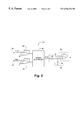
- FIG. 1 is a block diagram of a phase-compensated dual polarization receiver according to the present invention.
- FIG. 2 is a circuit diagram of the phase detector which is shown in FIG. 1 .
- a phase-compensated dual-polarization receiver 20 is shown in FIG. 1 .
- the receiver 20 is connected to two orthogonally polarized antennas 22 and 24 to receive signals therefrom.
- the conventional antennas 22 and 24 are adapted to receive linear, circular, or elliptical orthogonally polarized radio-frequency signals.
- the phase centers of the antennas 22 and 24 can be co-located to provide polarization diversity reception from one antenna structure.
- the phase centers of the antennas 22 and 24 can be spatially separated by at least one half of a wavelength of the carrier frequency of the transmitted signal to provide both polarization diversity reception and spatial diversity reception.
- the receiver 20 includes two intermediate frequency (IF) signal circuits 26 and 28 , a phase detector 30 , a loop filter 32 , a phase shifter 34 , and an IF signal amplifier 36 .
- IF intermediate frequency
- the signal received from antenna 22 is downconverted by the IF signal circuit 26 to an intermediate frequency signal which is provided to the IF signal amplifier 36 .
- the signal received from the other antenna 24 is initially phase shifted by phase shifter 34 so that its phase becomes substantially aligned with the signal received by antenna 22 .
- the phase shifted signal is downconverted by the IF signal circuit 28 to the intermediate frequency and provided to the IF signal amplifier 36 .
- the phase shifter 34 adjusts the phase of the signal in response to a phase error signal which is generated by the phase detector 30 .
- the phase shifter 34 can include the digital phase shifter integrated circuit which is manufactured by General Microwave Company as part number 7720A or a similar device.
- the phase detector 30 is inductively coupled to the output of the IF signal circuits 26 and 28 , at nodes 38 and 40 , to sense the downconverted IF signals.
- the phase detector 30 detects any phase difference between the sensed IF signals and outputs the phase error signal to the phase shifter 34 to drive the phase difference between the IF signals to zero.
- the phase detector 30 includes two small signal amplifiers 42 and 44 , a signal multiplier 46 , a low pass filter 48 , and a DC amplifier 50 .
- the small signal amplifiers 42 and 44 are inductively coupled, at nodes 38 and 40 , to the output of the IF signal circuits 26 and 28 (FIG. 1) to sense the IF signals.
- the sensed IF signals which are provided to the small signal amplifiers 42 and 44 can be represented as follows:
- V 1 ( t ) A Cos[ W LO t+ ⁇ 1 ( t )+90]
- V 1 (t) The sensed IF signal from the IF signal circuit 26 ;
- W LO Local oscillator frequency of IF signal circuits 26 and 28 ;
- ⁇ 1 (t) Phase angle of V 1 (t);
- V 2 ( t ) B Cos[W LO t+ ⁇ 2 ( t )+90]
- V 2 (t) The sensed IF signal from the IF signal circuit 28 ;
- W LO Local oscillator frequency of IF signal circuits 26 and 28 ;
- ⁇ 1 (t) Phase angle of V 1 (t);
- the amplified IF signals from the small signal amplifiers 42 and 44 are multiplied by the signal multiplier 46 to provide the following signal to the low pass filter 48 :
- V 3 ( t ) ABC Cos[ ⁇ 1 ( t ) ⁇ 2 ( t )+90]+ ABC Cos[2 W LO t+ ⁇ 1 ( t )+ ⁇ 2 ( t )+90]
- V 3 (t) multiplied IF signal generated by the signal multiplier 46 ;
- C gain product of the small signal amplifiers 42 and 44 and the signal multiplier 46 .
- the signal multiplier 46 can include conventional integrated circuitry for multiplying signals, such as part number MPY634 which is manufactured by Burr Brown Company or a similar device.
- the DC component of the multiplied IF signal is referred to as the phase error signal.
- the magnitude of the phase error signal is indicative of any phase difference between the sensed IF signals and, consequently, any phase difference between the signals received by the orthogonally polarized antennas 22 and 24 .
- the magnitude of the phase error signal is zero when the IF signals from the IF signal circuits 26 and 28 are substantially aligned and is a maximum when the IF signals are 90 degrees out of phase.
- the phase detector 30 controls the phase shifter 34 (FIG. 1) to drive the phase difference between the IF signals to zero and, thereby, provide substantial alignment between the IF signals.
- the phase error signal is amplified by the DC amplifier 50 and provided to the loop filter 32 (FIG. 1 ).
- the phase error signal is smoothed by the loop filter 32 to increase the stability of the phase control loop, which is formed by the phase detector 30 , loop filter 32 , phase shifter 34 , and IF signal circuit 28 , in driving any phase difference between the IF signals to zero.
- the loop filter 32 includes conventional integration circuitry such as a capacitor and resistor network (not shown).
- the substantially aligned IF signals from the IF signal circuits 26 and 28 are summed and amplified by a conventional IF signal amplifier 36 to form a combined polarization signal.
- the combined polarization signal is provided to conventional signal processing circuitry (not shown) for demodulation and other processing required by the communications device in which the receiver 20 is utilized.
- the receiver 20 compensates for multi-path characteristics and depolarization characteristics of the received signals.
- the antennas 22 and 24 are cross-polarized to receive the depolarized and polarized components of the received signal and are spatially separated to avoid any destructive interaction of the received multipath signals.
- the received signals are phase-aligned and then combined to generate an enhanced received signal irrespective of the depolarization or multipath characteristics of the received signal.
Abstract
Description
Claims (15)
Priority Applications (3)
| Application Number | Priority Date | Filing Date | Title |
|---|---|---|---|
| US08/910,297 US6546236B1 (en) | 1997-08-11 | 1997-08-11 | Phase-compensating polarization diversity receiver |
| AU89036/98A AU8903698A (en) | 1997-08-11 | 1998-08-10 | Phase-compensating polarization diversity receiver |
| PCT/US1998/016695 WO1999008400A2 (en) | 1997-08-11 | 1998-08-10 | Phase-compensating polarization diversity receiver |
Applications Claiming Priority (1)
| Application Number | Priority Date | Filing Date | Title |
|---|---|---|---|
| US08/910,297 US6546236B1 (en) | 1997-08-11 | 1997-08-11 | Phase-compensating polarization diversity receiver |
Publications (1)
| Publication Number | Publication Date |
|---|---|
| US6546236B1 true US6546236B1 (en) | 2003-04-08 |
Family
ID=25428585
Family Applications (1)
| Application Number | Title | Priority Date | Filing Date |
|---|---|---|---|
| US08/910,297 Expired - Lifetime US6546236B1 (en) | 1997-08-11 | 1997-08-11 | Phase-compensating polarization diversity receiver |
Country Status (3)
| Country | Link |
|---|---|
| US (1) | US6546236B1 (en) |
| AU (1) | AU8903698A (en) |
| WO (1) | WO1999008400A2 (en) |
Cited By (15)
| Publication number | Priority date | Publication date | Assignee | Title |
|---|---|---|---|---|
| US20030054790A1 (en) * | 2000-10-24 | 2003-03-20 | Yukitoshi Sanada | Receiver |
| US20030125001A1 (en) * | 2001-12-28 | 2003-07-03 | Murata Manufacturing Co., Ltd. | Signal reception circuit and communication device having the same |
| US20030186660A1 (en) * | 2002-03-27 | 2003-10-02 | Lg Electronics Inc. | Diversity receiving apparatus and method |
| US6751264B2 (en) * | 2001-07-27 | 2004-06-15 | Motorola, Inc. | Receiver and method therefor |
| US20050157684A1 (en) * | 2000-06-02 | 2005-07-21 | Nokia Networks Oy | Closed loop feedback system for improved down link performance |
| US20080096509A1 (en) * | 2006-10-19 | 2008-04-24 | Maxlinear, Inc. | Low Complexity Diversity Receiver |
| US20090103673A1 (en) * | 2007-10-22 | 2009-04-23 | Chung Shan Institute Of Science And Technology, Armaments Bureau, M.N.D. | Signal power combiner with dynamic phase compensation |
| US20090224983A1 (en) * | 2008-03-08 | 2009-09-10 | Qualcomm Incorporated | Methods and apparatus for supporting communications using horizontal polarization and dipole antennas |
| US20090227292A1 (en) * | 2008-03-08 | 2009-09-10 | Qualcomm Incorporated | Methods and apparatus for using polarized antennas in wireless networks including single sector base stations |
| US20090224990A1 (en) * | 2008-03-06 | 2009-09-10 | Qualcomm Incorporated | Methods and apparatus for supporting communications using a first polarization direction electrical antenna and a second polarization direction magnetic antenna |
| US20090224992A1 (en) * | 2008-03-08 | 2009-09-10 | Qualcomm Incorporated | Methods and apparatus for using polarized antennas in wireless networks including multi-sector base stations |
| US20090224847A1 (en) * | 2008-03-06 | 2009-09-10 | Qualcomm Incorporated | Methods and apparatus for supporting communications using antennas associated with different polarization directions |
| US20120326928A1 (en) * | 2010-02-25 | 2012-12-27 | Telefonaktiebolaget L M Ericsson (Publ) | Communication system node comprising a transformation matrix |
| CN104348536A (en) * | 2013-07-30 | 2015-02-11 | 瞻博网络公司 | Methods and apparatus for multi-polarization antenna systems |
| US20180026686A1 (en) * | 2015-02-12 | 2018-01-25 | Telefonaktiebolaget Lm Ericsson (Publ) | Microwave Radio Transmitter and Receiver for Polarization Misalignment Compensation |
Families Citing this family (2)
| Publication number | Priority date | Publication date | Assignee | Title |
|---|---|---|---|---|
| US8548031B2 (en) | 2009-12-30 | 2013-10-01 | Silicon Laboratories Inc. | Antenna diversity system with frame synchronization |
| US9178592B1 (en) | 2014-07-24 | 2015-11-03 | Silicon Laboratories Inc. | Systems and methods using multiple inter-chip (IC) links for antenna diversity and/or debug |
Citations (8)
| Publication number | Priority date | Publication date | Assignee | Title |
|---|---|---|---|---|
| US4186347A (en) | 1978-10-31 | 1980-01-29 | Nasa | Radio frequency arraying method for receivers |
| US4313220A (en) * | 1978-01-23 | 1982-01-26 | Northern Telecom Limited | Circuit and method for reducing polarization crosstalk caused by rainfall |
| US5263180A (en) | 1990-01-18 | 1993-11-16 | Fujitsu Limited | Space diversity reception system |
| EP0637878A2 (en) | 1993-08-02 | 1995-02-08 | Harris Corporation | Space diversity combiner |
| US5392054A (en) | 1993-01-29 | 1995-02-21 | Ericsson Ge Mobile Communications Inc. | Diversity antenna assembly for portable radiotelephones |
| EP0661834A2 (en) | 1993-12-28 | 1995-07-05 | Nec Corporation | Method and circuit for signal combining in a space diversity receiving system |
| US5568158A (en) * | 1990-08-06 | 1996-10-22 | Gould; Harry J. | Electronic variable polarization antenna feed apparatus |
| US5923714A (en) * | 1996-03-27 | 1999-07-13 | Samsung Electronics Co., Ltd. | Normalization circuit for preventing divergence of a normalizing voltage in a coupler used for diversity operation |
-
1997
- 1997-08-11 US US08/910,297 patent/US6546236B1/en not_active Expired - Lifetime
-
1998
- 1998-08-10 WO PCT/US1998/016695 patent/WO1999008400A2/en active Application Filing
- 1998-08-10 AU AU89036/98A patent/AU8903698A/en not_active Abandoned
Patent Citations (9)
| Publication number | Priority date | Publication date | Assignee | Title |
|---|---|---|---|---|
| US4313220A (en) * | 1978-01-23 | 1982-01-26 | Northern Telecom Limited | Circuit and method for reducing polarization crosstalk caused by rainfall |
| US4186347A (en) | 1978-10-31 | 1980-01-29 | Nasa | Radio frequency arraying method for receivers |
| US5263180A (en) | 1990-01-18 | 1993-11-16 | Fujitsu Limited | Space diversity reception system |
| US5568158A (en) * | 1990-08-06 | 1996-10-22 | Gould; Harry J. | Electronic variable polarization antenna feed apparatus |
| US5392054A (en) | 1993-01-29 | 1995-02-21 | Ericsson Ge Mobile Communications Inc. | Diversity antenna assembly for portable radiotelephones |
| EP0637878A2 (en) | 1993-08-02 | 1995-02-08 | Harris Corporation | Space diversity combiner |
| EP0661834A2 (en) | 1993-12-28 | 1995-07-05 | Nec Corporation | Method and circuit for signal combining in a space diversity receiving system |
| US5513222A (en) * | 1993-12-28 | 1996-04-30 | Nec Corporation | Combining circuit for a diversity receiving system |
| US5923714A (en) * | 1996-03-27 | 1999-07-13 | Samsung Electronics Co., Ltd. | Normalization circuit for preventing divergence of a normalizing voltage in a coupler used for diversity operation |
Cited By (32)
| Publication number | Priority date | Publication date | Assignee | Title |
|---|---|---|---|---|
| US7792206B2 (en) | 2000-06-02 | 2010-09-07 | Juha Ylitalo | Closed loop feedback system for improved down link performance |
| US8442144B2 (en) | 2000-06-02 | 2013-05-14 | Intellectual Ventures I Llc | Closed loop feedback system for improved down link performance |
| US20050157684A1 (en) * | 2000-06-02 | 2005-07-21 | Nokia Networks Oy | Closed loop feedback system for improved down link performance |
| US7139324B1 (en) * | 2000-06-02 | 2006-11-21 | Nokia Networks Oy | Closed loop feedback system for improved down link performance |
| US20100322337A1 (en) * | 2000-06-02 | 2010-12-23 | Juha Ylitalo | Closed loop feedback system for improved down link performance |
| US7844010B2 (en) | 2000-06-02 | 2010-11-30 | Juha Ylitalo | Closed loop feedback system for improved down link performance |
| US6862442B2 (en) * | 2000-10-24 | 2005-03-01 | Sony Corporation | Receiver |
| US20030054790A1 (en) * | 2000-10-24 | 2003-03-20 | Yukitoshi Sanada | Receiver |
| US6751264B2 (en) * | 2001-07-27 | 2004-06-15 | Motorola, Inc. | Receiver and method therefor |
| US20030125001A1 (en) * | 2001-12-28 | 2003-07-03 | Murata Manufacturing Co., Ltd. | Signal reception circuit and communication device having the same |
| US6928276B2 (en) * | 2001-12-28 | 2005-08-09 | Murata Manufacturing Co., Ltd. | Signal reception circuit and communication device having the same |
| US7363016B2 (en) * | 2002-03-27 | 2008-04-22 | Lg Electronics Inc. | Diversity receiving apparatus and method |
| US20030186660A1 (en) * | 2002-03-27 | 2003-10-02 | Lg Electronics Inc. | Diversity receiving apparatus and method |
| US20080096509A1 (en) * | 2006-10-19 | 2008-04-24 | Maxlinear, Inc. | Low Complexity Diversity Receiver |
| US20090103673A1 (en) * | 2007-10-22 | 2009-04-23 | Chung Shan Institute Of Science And Technology, Armaments Bureau, M.N.D. | Signal power combiner with dynamic phase compensation |
| US20090224847A1 (en) * | 2008-03-06 | 2009-09-10 | Qualcomm Incorporated | Methods and apparatus for supporting communications using antennas associated with different polarization directions |
| US8024003B2 (en) * | 2008-03-06 | 2011-09-20 | Qualcomm Incorporated | Methods and apparatus for supporting communications using antennas associated with different polarization directions |
| US8326249B2 (en) | 2008-03-06 | 2012-12-04 | Qualcomm Incorporated | Methods and apparatus for supporting communications using a first polarization direction electrical antenna and a second polarization direction magnetic antenna |
| US20090224990A1 (en) * | 2008-03-06 | 2009-09-10 | Qualcomm Incorporated | Methods and apparatus for supporting communications using a first polarization direction electrical antenna and a second polarization direction magnetic antenna |
| US20090224983A1 (en) * | 2008-03-08 | 2009-09-10 | Qualcomm Incorporated | Methods and apparatus for supporting communications using horizontal polarization and dipole antennas |
| US8594732B2 (en) | 2008-03-08 | 2013-11-26 | Qualcomm Incorporated | Methods and apparatus for using polarized antennas in wireless networks including multi-sector base stations |
| US20090224992A1 (en) * | 2008-03-08 | 2009-09-10 | Qualcomm Incorporated | Methods and apparatus for using polarized antennas in wireless networks including multi-sector base stations |
| US7991374B2 (en) * | 2008-03-08 | 2011-08-02 | Qualcomm Incorporated | Methods and apparatus for supporting communications using horizontal polarization and dipole antennas |
| US20090227292A1 (en) * | 2008-03-08 | 2009-09-10 | Qualcomm Incorporated | Methods and apparatus for using polarized antennas in wireless networks including single sector base stations |
| US8594733B2 (en) | 2008-03-08 | 2013-11-26 | Qualcomm Incorporated | Methods and apparatus for using polarized antennas in wireless networks including single sector base stations |
| US20120326928A1 (en) * | 2010-02-25 | 2012-12-27 | Telefonaktiebolaget L M Ericsson (Publ) | Communication system node comprising a transformation matrix |
| US9728850B2 (en) * | 2010-02-25 | 2017-08-08 | Telefonaktiebolaget Lm Ericsson (Publ) | Communication system node comprising a transformation matrix |
| CN104348536A (en) * | 2013-07-30 | 2015-02-11 | 瞻博网络公司 | Methods and apparatus for multi-polarization antenna systems |
| EP2840655A1 (en) * | 2013-07-30 | 2015-02-25 | Juniper Networks, Inc. | Methods and apparatus for multi-polarization antenna systems |
| CN104348536B (en) * | 2013-07-30 | 2018-02-23 | 瞻博网络公司 | Method and apparatus for multi-polarization antenna system |
| US20180026686A1 (en) * | 2015-02-12 | 2018-01-25 | Telefonaktiebolaget Lm Ericsson (Publ) | Microwave Radio Transmitter and Receiver for Polarization Misalignment Compensation |
| US10171143B2 (en) * | 2015-02-12 | 2019-01-01 | Telefonaktiebolaget Lm Ericsson (Publ) | Microwave radio transmitter and receiver for polarization misalignment compensation |
Also Published As
| Publication number | Publication date |
|---|---|
| WO1999008400A2 (en) | 1999-02-18 |
| WO1999008400A3 (en) | 1999-04-29 |
| AU8903698A (en) | 1999-03-01 |
Similar Documents
| Publication | Publication Date | Title |
|---|---|---|
| US6546236B1 (en) | Phase-compensating polarization diversity receiver | |
| CA2036482C (en) | Interference cancellation system for interference signals received with differing phases | |
| US9537468B2 (en) | Reflective vector modulators | |
| KR0164250B1 (en) | Receiver and repeater for spread spectrum communicaton | |
| EP0762660B1 (en) | Apparatus and method for electronic polarization correction | |
| US5710995A (en) | Adaptive antenna receiver | |
| US8200302B2 (en) | Mobile wireless communication apparatus having a plurality of antenna elements | |
| US7171175B2 (en) | Method for receiving radio frequency signal and a receiver device | |
| US20080001820A1 (en) | Methods and Systems for Tracking Signals with Diverse Polarization Properties | |
| RO120442B1 (en) | Method and system for communications using electromagnetic waves | |
| US20020190908A1 (en) | Method and apparatus for wireless communication utilizing electrical and magnetic polarization | |
| JPH01212035A (en) | Electromagnetic field diversity reception system | |
| JPWO2005011148A1 (en) | Millimeter-wave wireless communication method and system | |
| Chen et al. | Overview on the phase conjugation techniques of the retrodirective array | |
| US20070279284A1 (en) | Method To Design Polarization Arrangements For Mimo Antennas Using State Of Polarization As Parameter | |
| Parsons et al. | Diversity techniques for mobile radio reception | |
| Miura et al. | A DBF self-beam steering array antenna for mobile satellite applications using beam-space maximal-ratio combination | |
| EP0348940B1 (en) | Uplink cross-polarization interference canceller using correlation calculator and stepwise tracking controller | |
| EP0642232A1 (en) | Radio communication system | |
| US11196160B2 (en) | Dual-polarized retrodirective array and multi-frequency antenna element | |
| Keusgen | On limits of wireless communications when using multiple dual-polarized antennas | |
| US4611212A (en) | Field component diversity antenna and receiver arrangement | |
| US7110733B1 (en) | Array antenna radio communication apparatus and weight coefficient generating method | |
| RU2296398C1 (en) | Device for forming polarization of radio-signals of receiver-transmitters | |
| Taga | Characteristics of space‐diversity branch using parallel dipole antennas in mobile radio communications |
Legal Events
| Date | Code | Title | Description |
|---|---|---|---|
| AS | Assignment |
Owner name: ERICSSON INC., NORTH CAROLINA Free format text: ASSIGNMENT OF ASSIGNORS INTEREST;ASSIGNORS:CANADA, ROBERT O.;RAWLE, WALTER D.;REEL/FRAME:008846/0438 Effective date: 19970807 |
|
| STCF | Information on status: patent grant |
Free format text: PATENTED CASE |
|
| FPAY | Fee payment |
Year of fee payment: 4 |
|
| FPAY | Fee payment |
Year of fee payment: 8 |
|
| AS | Assignment |
Owner name: RESEARCH IN MOTION LIMITED, CANADA Free format text: ASSIGNMENT OF ASSIGNORS INTEREST;ASSIGNOR:TELEFONAKTIEBOLAGET L M ERICSSON (PUBL);REEL/FRAME:026251/0104 Effective date: 20110325 |
|
| FPAY | Fee payment |
Year of fee payment: 12 |
|
| AS | Assignment |
Owner name: BLACKBERRY LIMITED, ONTARIO Free format text: CHANGE OF NAME;ASSIGNOR:RESEARCH IN MOTION LIMITED;REEL/FRAME:038025/0078 Effective date: 20130709 |