US6580821B1 - Method for computing the location and orientation of an object in three dimensional space - Google Patents
Method for computing the location and orientation of an object in three dimensional space Download PDFInfo
- Publication number
- US6580821B1 US6580821B1 US09/538,208 US53820800A US6580821B1 US 6580821 B1 US6580821 B1 US 6580821B1 US 53820800 A US53820800 A US 53820800A US 6580821 B1 US6580821 B1 US 6580821B1
- Authority
- US
- United States
- Prior art keywords
- points
- dimensional
- solutions
- computing
- marked
- Prior art date
- Legal status (The legal status is an assumption and is not a legal conclusion. Google has not performed a legal analysis and makes no representation as to the accuracy of the status listed.)
- Expired - Lifetime
Links
Images


Classifications
-
- G—PHYSICS
- G06—COMPUTING; CALCULATING OR COUNTING
- G06T—IMAGE DATA PROCESSING OR GENERATION, IN GENERAL
- G06T7/00—Image analysis
- G06T7/70—Determining position or orientation of objects or cameras
- G06T7/73—Determining position or orientation of objects or cameras using feature-based methods
- G06T7/74—Determining position or orientation of objects or cameras using feature-based methods involving reference images or patches
-
- G—PHYSICS
- G06—COMPUTING; CALCULATING OR COUNTING
- G06V—IMAGE OR VIDEO RECOGNITION OR UNDERSTANDING
- G06V10/00—Arrangements for image or video recognition or understanding
- G06V10/70—Arrangements for image or video recognition or understanding using pattern recognition or machine learning
- G06V10/74—Image or video pattern matching; Proximity measures in feature spaces
- G06V10/75—Organisation of the matching processes, e.g. simultaneous or sequential comparisons of image or video features; Coarse-fine approaches, e.g. multi-scale approaches; using context analysis; Selection of dictionaries
- G06V10/757—Matching configurations of points or features
-
- G—PHYSICS
- G06—COMPUTING; CALCULATING OR COUNTING
- G06V—IMAGE OR VIDEO RECOGNITION OR UNDERSTANDING
- G06V40/00—Recognition of biometric, human-related or animal-related patterns in image or video data
- G06V40/10—Human or animal bodies, e.g. vehicle occupants or pedestrians; Body parts, e.g. hands
- G06V40/16—Human faces, e.g. facial parts, sketches or expressions
- G06V40/172—Classification, e.g. identification
Definitions
- This invention relates to computer vision and more particularly to the computation of the location and orientation (alternatively referred to as “pose”) of an object in three dimensional (3D) space.
- Apparatus for capturing 3-dimensional (henceforth, 3D) models of people's faces are known in the art. These apparatus simultaneously capture pictures of the faces in registration with the 3D models that are captured.
- the 3D models consist of the 3-dimensional coordinates of a large number of points on the surface of the face, typically on the order of 640 ⁇ 640, along with the color picture value at each point. This provides the possibility of realistic computer graphics rendering of the faces from any vantage point. It is envisioned that this device can be used to capture a large number of face models. In some applications, this number could reach on the order of one million faces or more.
- One application of this device is face identification, i.e., given a query consisting of an arbitrary two-dimensional (2D) photograph of a face, to search a large database of previously captured 3D models of faces to find the model which best matches the 2D photograph.
- 2D two-dimensional
- the methods of the present invention fall into the first class.
- Features that have been used by prior artisans range from hand-selected points, to automatically detected points such as “corners”, extrema, lines, line junctions, and curves.
- the present invention deals only with the simplest of these methods, which takes as input 2 sets of points.
- the first set of points is marked by hand on a 3D model, resulting in 3D coordinates of the points.
- the second set of points is similarly marked by hand on a 2D image of a similar object.
- the correspondence between the 3D and 2D points is known, i.e., for each of the 3D points there is exactly one 2D point which is known to correspond to it, and vice versa.
- a 3D point “corresponds” to a 2D point, it is meant that the points represent the same feature of the object, e.g., the left corner of the left eye of some person's face, or the left rear corner of the left wing of an airplane.
- the problem to be solved is to compute the rigid motion of the 3D point set, all points moving identically together, such that the perspective projection (i.e., the camera image) of the 3D point set will be the 2D point set. This is equivalent to finding the position and orientation of a perspective projection camera so that the picture it takes of the 3D point set will be the 2D point set. This is sometimes called the “perspective n-point problem,” where n is the number of points involved.
- the first problem is that when there are more than 3 pairs of corresponding points, it is not in general possible to obtain a closed form solution. For larger numbers of points, a least squares approach is required. In general, because of the nonlinear nature of the perspective projection (i.e., perspective contains a division by the z coordinate), and the nonlinear effects in the 2D image of rotations in 3D space, the least squares problem must be solved by iterative methods. Iterative methods are slow compared to closed form solutions, and in the applications of concern, it will eventually be required to solve this problem for up to hundreds of millions or more different sets of 3D points for each query, so that speed is important. It is further desirable that for graphic display purposes, the solution be so fast that it can be done in real time to provide a smooth graphic display of the effect of altering point positions on the resulting solution.
- a method for computing the location and orientation of an object in three-dimensional space comprises the steps of: (a) marking a plurality of feature points on a three-dimensional model and corresponding feature points on a two-dimensional query image; (b) for all possible subsets of three two-dimensional feature points marked in step (a), computing the four possible three-dimensional rigid motion solutions of a set of three points in three-dimensional space such that after each of the four rigid motions, under a fixed perspective projection, the three three-dimensional points are mapped precisely to the three corresponding two-dimensional points; (c) for each solution found in step (b), computing an error measure derived from the errors in the projections of all three-dimensional marked points in the three-dimensional model which were not among the three points used in the solution, but which did have corresponding marked points in the two-dimensional query image; (d) ranking the solutions from step (c) based on the computed error measure; and (e) selecting the best solution based on the ranking in step (d).
- the method further comprises, after step (a), the step of computing a predetermined number of perturbed points derived from each of the feature points wherein the computation of step (b) is on all possible subsets of three two-dimensional points marked in the query image, and in addition on the corresponding perturbed points.
- the predetermined number of perturbed points are obtained by sampling from a spherical Gaussian distribution.
- the method further comprises, after step (d), the steps of: (i) choosing a subset of the solutions from step (c) based on the ranking of step (d); (ii) computing a predetermined number of perturbed points derived from each of the subset of the solutions; (iii) repeating step (b) on the predetermined number of perturbed points; and (iv) repeating step (c) for each solution found in step (iii); wherein the ranking of step (d) is based on the error computed in both steps (c) and (iv).
- the subset of solutions chosen is a predetermined portion of the ranked solutions, such as the top 10% of the ranked solutions.
- program storage device readable by machine, tangibly embodying a program of instructions executable by the machine to perform the method steps of the methods and variations thereof of the present invention and a computer program product embodied in a computer-readable medium for carrying out the methods, and variations thereof, of the present invention.
- the computer program has modules corresponding to the steps of the methods and variations thereof of the present invention.
- FIG. 1 illustrates a schematic representation of a two dimensional mapping of a three dimensional model of a human face.
- FIG. 2 illustrates a schematic representation of a two dimensional query photograph.
- FIG. 3 illustrates the model points of the three dimensional model when imaged by a camera projection transformation resulting in the best approximation to the two dimensional query points that are marked in a query.
- FIG. 4 illustrates the two dimensional query image of FIG. 2 and the three dimensional model, both with all visible feature points marked.
- FIG. 5 illustrates a graphical representation of the perspective projection of a point p in 3-space to a point q in an image plane.
- FIG. 6 illustrates a tetrahedron LABC with vertices L, A, B, and C.
- FIG. 7 is a flowchart illustrating the method of the present invention.
- FIG. 8 is a flowchart illustrating a first variation of the method of FIG. 7 .
- FIGS. 9 a and 9 b are flowcharts illustrating a second variation of the method of FIG. 7 .
- the methods of the present invention are pose estimation methods.
- the methods of the present invention solve the problem of determining the best approximate pose of each 3D model to account for the appearance of the query, i.e., the position and orientation of the model in three dimensional space that would lead to an image most similar to the query.
- the methods of the present invention do this using a small number of manually selected corresponding points in the 3D model and the 2D query.
- three 2D-3D point-pairs are considered at a time to compute a tentative solution, which is computable in closed form as the solution to a quartic equation.
- a Gaussian jittering technique is preferably used to reverse the effect of presumed Gaussian errors in the manual marking of the points.
- the methods of the present invention is similar to the RANSAC method of the prior art; however, there are notable differences.
- RANSAC was developed primarily to solve the same problem, i.e., the “perspective n point problem”, in which one is given the relative positions of n points in 3D space, and an equal number of points in a 2D image, and the problem is to find the perspective projection that maps the 3D points to the 2D points. The correspondence between the 2D and 3D points is known.
- the RANSAC method tries to precompute a reasonable error bound, and then tries subsets of the data points. It removes points from each subset in an effort to achieve an acceptable total error.
- the subsets are chosen either at random or deterministically, and the authors give an analysis indicating how many subsets and what size of subset are appropriate based on the number of available points, and the expected error statistics.
- RANSAC is intended to be used in the presence of a fairly large number of points, so that exhaustive testing of all combinations is not contemplated.
- RANSAC uses as its basic computation either closed form solutions on three points, or least squares solutions on some larger number of points. There are those in the art who have clearly shown for the first time in the computer vision literature, the fact that for three points, there is a straightforward solution involving solving a quartic equation, which in general can have four physically meaningful solutions.
- the Best Triangle methods of the present invention use, as their fundamental computation, a closed form solution for three points, and its algorithm for that solution is based on the RANSAC quartic exposition.
- the Best Triangle methods of the present invention never use least squares or any iterative method of solution, as do the methods of the prior art.
- the Best Triangle methods of the present invention compute their solution using only the three points.
- the “quality” of that solution is based on how well the remaining points fit, but the solution itself is not affected by any aspect of the errors on the other points.
- the Best Triangle methods of the present invention choose their final solution by ranking all solutions for three points by this “quality” factor; the solution with the lowest residuals on the remaining points is determined to be the best solution.
- the solution is based on three points; presumably there are three points in the data which are not grossly wrong, so one expects that the solution will at least be reasonable.
- grossly wrong points participate in choosing which solution is the best, they can do so in one of two ways.
- they can be one of the “other points”, i.e., not one of the three used in computing the solution.
- the bad points only affect the competition among solutions. If these points are grossly wrong, then for all reasonable solutions of three points, one would expect that they contribute an approximately equal grossly wrong error, and therefore do not make a significant difference in choosing among solutions.
- a grossly wrong point is one of the three being used to compute the solution, one expects that it will skew the solution so much that the ranking errors contributed by all the other points will easily eliminate this solution from the competition.
- the Best Triangle methods of the present invention are extremely fast, as compared to the methods of the prior art, since there is no need for iterative solutions.
- the Best Triangle methods of the present invention also add another technique to the computation.
- the Best Triangle methods In order to compensate for the fact that only three points are being used for a solution, and assuming that the data points differ from their true values by a Gaussian error, the Best Triangle methods artificially generate a Gaussian cloud of several points around each data point, and solves the three point problem for all combinations of the points in the cloud. This offers the possibility of improving the three point solution to more closely approximate the correct solution.
- the alignment methods of the prior art give complexity bounds such as in equation 1 above, they do not contemplate exhaustively checking all possible triples, since they are in an environment where there may be a very large number, perhaps thousands, of points to draw triples from. Instead, they concern themselves with methods for pruning the search of triples, such as heuristic criteria for the likelihood that a given 3D point may be matched to a 2D point in the query. They are also in an environment where the points themselves are highly unreliable, since they have been extracted automatically by machine. Finally, the quality measure they use is not point-based. Rather, it is based on edges that have been extracted in the query image. This also is dictated by the fact that this is more reliable than errors of a large number of unreliable points.
- the alignment methods of the prior art try to solve is therefore rather different than that addressed by the methods of the present invention.
- the alignment methods of the prior art use a fairly small set (e.g., numbering 10) of 3D models, each of which are considerably different, and they extract large numbers of unreliable points automatically. They do not know the 2D-3D point correspondences in advance, and therefore, must guess these. Most of their effort is involved in dealing with large numbers of unreliable points, they do not consider the error on the points not used for the rigid motion solution, but rather use errors related to line segments. What's more, they use an orthographic or orthographic-plus-scale approximation to perspective projection.
- the present invention by contrast, is intended for a large set (e.g., up to 1 million) of 3D models, each of which are quite similar, and it extracts a small number of relatively reliable points manually.
- the invention knows the 2D-3D point correspondences in advance, and therefore has no need to guess these.
- Most of the present invention's effort is involved in performing an exhaustive solution for all choices of point triples; it has no interest in edges of any kind, and only uses errors on the remaining corresponding points. What's more, it uses perspective projection exactly, not an approximation to perspective projection.
- FIG. 1 is a schematic representation of a two dimensional mapping of a three dimensional model of a human face 100 .
- the face 100 has the appearance of a photograph, but at every point of this 2D representation has associated with it a datum of depth, so that although only 2D data is displayed, 3D data is nevertheless available.
- a human operator uses an input device such as a mouse to click on some number of points 102 which are defined as specific features of the face. In the case of FIG.
- 1, 12 points have been defined and marked; these are defined as the left and right corners of each eye, the pupil of each eye, the left and right corners of the lips, the center of the boundary between the two lips, and three points where the nose meets the rest of the face, at the left and right extremities of the base of the nose, and the center of the base of the nose.
- these are the typical 12 features that are used. Obviously, larger or smaller numbers of feature points can be used.
- a 2D query photograph 200 is presented to the system.
- a human operator marks as many of the 12 defined features 202 as are visible in the query photograph 200 . Note that these marks 202 are not interchangeable, so that mark number n always indicates feature number n; if feature number n is not visible, then no mark number n is made.
- each 3D model 100 was responsible for the 2D query image 200 .
- the problem, for each 3D model 100 is to discover the translation and rotation (i.e., rigid motion) of the 3D model 100 so that its model points 102 , when imaged by the camera projection transformation 300 —a perspective projection—result in the best approximation to the 2D query points 202 that were marked in the query.
- FIG. 4 200 indicates the 2D query image, and 100 indicates the 3D model, both with all visible feature points marked 202 , 102 , respectively. (In this case, all 12 feature points were visible in the 2D query.)
- We systematically consider each triple 400 of feature points in the query. In this case, because there are 12 feature points, there are 12*11*10/6 220 such triples.
- Each such triple corresponds to a unique triple of feature points 402 in each 3D model 100 , since we know the correspondence between the features in the model and the query.
- each of these triples is joined by a triangle 404 , 406 . Note that the triangle 406 in the 3D model 100 , is actually a triangle in three dimensional space, although it is being depicted in the figure in two dimensions only.
- the first thing that must be computed is the rigid motion of the 3D model triangle 406 , that results, under a fixed camera projection to 2D, in the 2D query triangle 404 . Because there are two sets of only three points involved, this rigid motion can be computed in closed form by solving a quartic equation, which is known in principle from prior art.
- one way of defining perspective projection is that we are given a center of projection L, which is a point in 3-space, and a location and orientation of the image plane in 3-space.
- the perspective projection of a point p in 3-space to a point q in the image plane is performed by taking the unique line which passes through both q and L in 3-space, and defining q as the unique point where this line intersects the image plane. This obviously excludes the degenerate case where the image plane contains the center of projection.
- A*, B*, C* be 3 points in the image plane.
- A′, B′, C′ be 3 points in 3-space.
- ⁇ A ⁇ B ⁇ , ⁇ B ⁇ C ⁇ , and ⁇ C ⁇ A ⁇ have the same values as ⁇ A′ ⁇ B′ ⁇ , ⁇ B′ ⁇ C′ ⁇ , and ⁇ C′ ⁇ A′ ⁇ , respectively.
- Q ab , Q ac , and Q bc are the angles that LA makes with LB, LA with LC, and LB wth LC, respectively.
- K1 ( R bc ) 2 ( R ac ) 2 ( 5 )
- K2 ( R bc ) 2 ( R ab ) 2 ( 6 )
- x b/a (7)
- G 1 4( K 1 K 2 +K 1 ⁇ K 2 ) K 2 (1 ⁇ K 1 )cos Q ab +4 K 1 [( K 1 K 2 ⁇ K 1 +K 2 )cos Q ac cos Q bc +2 K 1 K 2 cos Q ab cos 2 Q ac ] (12)
- the remaining-point error will depend on what happens to the remaining n-3 points, i.e., to the points (4, 5, . . . , n).
- ⁇ z ⁇ means the usual (Euclidean) norm in R 2 .
- z (z x , z y ), where z x is the x component of z, and z y is the y component of z.
- x and y stand for the axes of R 2 , unlike above and below, where we are using x and y as points in R 2 and R 3 , respectively. Then the norm is defined by
- E i is known as the square error at point i.
- the winning solution is the one which achieves the lowest value of E tot .
- Hand marked points can suffer from a certain amount of imprecision. This can arise from various sources, including resolution limitations of the devices being used to aid in the marking, as well as the fact that the features corresponding to the points being marked may not have perfectly well-defined locations in either the 3D model or the 2D query image.
- the methods of the present invention contain an optional technique which attempts to find better points than the exact points presented to it in the data. This is done based on the assumption that the marked points obey a spherical Gaussian distribution with a mean at the “true” point position. I.e., if the true point position is at (u,v) in the query, then this module assumes that the probability that this point was actually marked at (x,y) is given by:
- A is a normalization factor
- s is the standard deviation, which is selected ad hoc, typically at about 1-3 pixel diameters.
- the algorithm uses such a technique to generate a cloud of a small number of points around the data value (x,y).
- the number of perturbed points to use in such a cloud is fixed for a given run of the algorithm. It can, however, be varied from query to query, but for each query, the number of points must be the same for all data points that are to be perturbed.
- a cost-saving variation of this procedure is to first solve for the pose of all triples without noise, i.e. solve using the unperturbed values of q i . Then, sort the triples used in this unperturbed stage based on the quality score. Finally, run the additional perturbed k triples for only the few best solutions. There is no need to add noise to triples that provided very bad quality scores in the first place, since it is very unlikely that such small perturbations will lead to large improvements in the quality.
- the methods of the present invention have been implemented in the C programming language.
- the methods used to compute the solution of the perspective three point problem is the one presented in the RANSAC method. This reduces the problem to solving a quartic equation.
- the implementation uses a quartic equation solver available in the public domain on the internet.
- the primary advantage over other methods is a better tradeoff between speed and robustness.
- the methods of the present invention are both extremely fast and quite robust.
- the methods of the present invention are particularly well suited to the application, where a small number of manually marked points with known correspondences must be used to find pose.
- the method of the present invention comprises marking a predetermined number of feature points, typically by a human operator, on both a 3D model and a 2D query image at steps 702 and 704 , respectively.
- the number of feature points chosen is in the range of 8-12.
- all subsets of three pairs of corresponding feature points are generated.
- the four possible three-dimensional rigid motions of the three points in three-dimensional space are computed at step 708 , such that after each of these four rigid motions, a fixed perspective projection maps the three three-dimensional points precisely to the three corresponding two-dimensional points.
- Step 708 is then repeated for all possible subsets of three two-dimensional points marked in the query.
- an error measure is computed at step 710 which is derived from the errors in the projections of all three-dimensional marked points in the model which were not among the three points used in that solution, but which did have corresponding marked points in the two-dimensional query.
- the solutions are ranked based on the error computed at step 710 .
- the best solution is selected based on the ranking of step 712 .
- steps 702 , 704 , and 706 are carried out as in the method discussed above.
- step 802 a small number, about 10, perturbed points are computed which are derived from each of the original feature points. These points are typically obtained by sampling from a spherical Gaussian distribution.
- Step 804 is similar to step 708 discussed above with regard to the above method, except that the computation is also carried out for the corresponding perturbed points from step 802 .
- an error measure is computed at step 710 which is derived from the errors in the projections of all three-dimensional marked points in the model which were not among the three points used in that solution, but which did have corresponding marked points in the two-dimensional query.
- the solutions are ranked based on the error computed at step 710 .
- the best solution is selected based on the ranking of step 712 .
- the second variation of the methods of the present invention starts with the same steps 702 , 704 , 706 , 708 , 710 , and 712 as the method described above with regard to FIG. 7 .
- step 714 instead of step 714 , where the best solution is selected based on the ranking of step 712 , a subset of the most promising solutions are selected at step 902 based on the ranking of step 712 .
- step 904 a small number, about 10, of perturbed points are computed at step 904 which are derived from each of the original feature points which are members of promising subset. Unlike step 802 , only the “promising” subset of point-pair triples are used.
- step 906 the computation of step 804 is carried out on the corresponding perturbed points from step 904 .
- step 908 for each solution found in step 906 , an error measure is computed which is derived from the errors in the projections of the corresponding perturbed three-dimensional marked points in the model which were not among the three points used in that solution, but which did have corresponding marked points in the two-dimensional query.
- the solutions from steps 708 and 906 are ranked based on the error computed in steps 710 and 908 .
- best solution is selected based on the ranking of step 910 .
Abstract
A method for computing the location and orientation of an object in three-dimensional space. The method comprises the steps of: (a) marking a plurality of feature points on a three-dimensional model and corresponding feature points on a two-dimensional query image; (b) for all possible subsets of three two-dimensional feature points marked in step (a), computing the four possible three-dimensional rigid motion solutions of a set of three points in three-dimensional space such that after each of the four rigid motions, under a fixed perspective projection, the three three-dimensional points are mapped precisely to the three corresponding two-dimensional points; (c) for each solution found in step (b), computing an error measure derived from the errors in the projections of all three-dimensional marked points in the three-dimensional model which were not among the three points used in the solution, but which did have corresponding marked points in the two-dimensional query image; (d) ranking the solutions from step (c) based on the computed error measure; and (e) selecting the best solution based on the ranking in step (d). Also provided is a program storage device readable by machine, tangibly embodying a program of instructions executable by the machine to perform the method steps of the present invention and a computer program product embodied in a computer-readable medium for carrying out the methods of the present invention.
Description
1. Field of the Invention
This invention relates to computer vision and more particularly to the computation of the location and orientation (alternatively referred to as “pose”) of an object in three dimensional (3D) space.
2. Prior Art
Apparatus for capturing 3-dimensional (henceforth, 3D) models of people's faces are known in the art. These apparatus simultaneously capture pictures of the faces in registration with the 3D models that are captured. The 3D models consist of the 3-dimensional coordinates of a large number of points on the surface of the face, typically on the order of 640×640, along with the color picture value at each point. This provides the possibility of realistic computer graphics rendering of the faces from any vantage point. It is envisioned that this device can be used to capture a large number of face models. In some applications, this number could reach on the order of one million faces or more.
One application of this device is face identification, i.e., given a query consisting of an arbitrary two-dimensional (2D) photograph of a face, to search a large database of previously captured 3D models of faces to find the model which best matches the 2D photograph.
There are numerous obstacles to be overcome to accomplish this.
In general, there is no knowledge or control of the conditions under which the query photograph was acquired. Therefore, the pose (i.e. the position and orientation of the subject) and the lighting conditions of the query photograph are unknown.
There have been numerous approaches to the problem of face recognition. We focus on one class of paradigms for matching a query to a model in this setting, which begins with the task of determining the pose of the face in the query, where the “pose” is defined as the 3D position and orientation of the face.
It is that task, pose determination, that the present invention, is concerned with. There is considerable prior art concerned with finding the pose of 3D objects given a 2D photograph. The present invention is interested in the case where a set of 3D models is available. The methods of the prior art for dealing with this problem can be divided into two classes:
1. Those based on “features” extracted from the 2D image which are compared to corresponding features in some 3D model; and
2. Those that use the image directly.
The methods of the present invention fall into the first class. Features that have been used by prior artisans range from hand-selected points, to automatically detected points such as “corners”, extrema, lines, line junctions, and curves. The present invention deals only with the simplest of these methods, which takes as input 2 sets of points. The first set of points is marked by hand on a 3D model, resulting in 3D coordinates of the points. The second set of points is similarly marked by hand on a 2D image of a similar object. The correspondence between the 3D and 2D points is known, i.e., for each of the 3D points there is exactly one 2D point which is known to correspond to it, and vice versa. By saying that a 3D point “corresponds” to a 2D point, it is meant that the points represent the same feature of the object, e.g., the left corner of the left eye of some person's face, or the left rear corner of the left wing of an airplane. The problem to be solved is to compute the rigid motion of the 3D point set, all points moving identically together, such that the perspective projection (i.e., the camera image) of the 3D point set will be the 2D point set. This is equivalent to finding the position and orientation of a perspective projection camera so that the picture it takes of the 3D point set will be the 2D point set. This is sometimes called the “perspective n-point problem,” where n is the number of points involved.
There have been many practitioners who have crafted solutions to the perspective n point problem. These range from relatively straightforward least squares solutions, to statistical selection techniques, through what is now commonly called “recognition by alignment.”
There are several problems with existing methods for this problem. The first problem is that when there are more than 3 pairs of corresponding points, it is not in general possible to obtain a closed form solution. For larger numbers of points, a least squares approach is required. In general, because of the nonlinear nature of the perspective projection (i.e., perspective contains a division by the z coordinate), and the nonlinear effects in the 2D image of rotations in 3D space, the least squares problem must be solved by iterative methods. Iterative methods are slow compared to closed form solutions, and in the applications of concern, it will eventually be required to solve this problem for up to hundreds of millions or more different sets of 3D points for each query, so that speed is important. It is further desirable that for graphic display purposes, the solution be so fast that it can be done in real time to provide a smooth graphic display of the effect of altering point positions on the resulting solution.
Therefore it is an object of the present invention to provide a method for computing the location and orientation of an object in three dimensional space which is fast as compared to the methods of the prior art.
It is a further object of the present invention to provide a method for computing the location and orientation of an object in three dimensional space which is not only fast as compared to the methods of the prior art but also robust.
It is yet a further object of the present invention to provide a method for computing the location and orientation of an object in three dimensional space which is well suited to an application, where a small number of manually marked points with known correspondences must be used to find pose.
It is yet a further object of the present invention to provide a method for computing the location and orientation of an object in three dimensional space which does not require knowledge of a camera model, or need to solve for a camera model.
It is still yet a further object of the present invention to provide a method for computing the location and orientation of an object in three dimensional space which is computationally simpler than the heuristics and iterative solutions of the prior art.
Accordingly, a method for computing the location and orientation of an object in three-dimensional space is provided. The method comprises the steps of: (a) marking a plurality of feature points on a three-dimensional model and corresponding feature points on a two-dimensional query image; (b) for all possible subsets of three two-dimensional feature points marked in step (a), computing the four possible three-dimensional rigid motion solutions of a set of three points in three-dimensional space such that after each of the four rigid motions, under a fixed perspective projection, the three three-dimensional points are mapped precisely to the three corresponding two-dimensional points; (c) for each solution found in step (b), computing an error measure derived from the errors in the projections of all three-dimensional marked points in the three-dimensional model which were not among the three points used in the solution, but which did have corresponding marked points in the two-dimensional query image; (d) ranking the solutions from step (c) based on the computed error measure; and (e) selecting the best solution based on the ranking in step (d).
In a first variation of the method of the present invention, the method further comprises, after step (a), the step of computing a predetermined number of perturbed points derived from each of the feature points wherein the computation of step (b) is on all possible subsets of three two-dimensional points marked in the query image, and in addition on the corresponding perturbed points. Typically, the predetermined number of perturbed points are obtained by sampling from a spherical Gaussian distribution.
In a second variation of the method of the present invention, the method further comprises, after step (d), the steps of: (i) choosing a subset of the solutions from step (c) based on the ranking of step (d); (ii) computing a predetermined number of perturbed points derived from each of the subset of the solutions; (iii) repeating step (b) on the predetermined number of perturbed points; and (iv) repeating step (c) for each solution found in step (iii); wherein the ranking of step (d) is based on the error computed in both steps (c) and (iv). Preferably, the subset of solutions chosen is a predetermined portion of the ranked solutions, such as the top 10% of the ranked solutions.
Still further provided is a program storage device readable by machine, tangibly embodying a program of instructions executable by the machine to perform the method steps of the methods and variations thereof of the present invention and a computer program product embodied in a computer-readable medium for carrying out the methods, and variations thereof, of the present invention. Preferably, the computer program has modules corresponding to the steps of the methods and variations thereof of the present invention.
These and other features, aspects, and advantages of the methods of the present invention will become better understood with regard to the following description, appended claims, and accompanying drawings where:
FIG. 1 illustrates a schematic representation of a two dimensional mapping of a three dimensional model of a human face.
FIG. 2 illustrates a schematic representation of a two dimensional query photograph.
FIG. 3 illustrates the model points of the three dimensional model when imaged by a camera projection transformation resulting in the best approximation to the two dimensional query points that are marked in a query.
FIG. 4 illustrates the two dimensional query image of FIG. 2 and the three dimensional model, both with all visible feature points marked.
FIG. 5 illustrates a graphical representation of the perspective projection of a point p in 3-space to a point q in an image plane.
FIG. 6 illustrates a tetrahedron LABC with vertices L, A, B, and C.
FIG. 7 is a flowchart illustrating the method of the present invention.
FIG. 8 is a flowchart illustrating a first variation of the method of FIG. 7.
FIGS. 9a and 9 b are flowcharts illustrating a second variation of the method of FIG. 7.
Although this invention is applicable to numerous and various types of objects to be recognized, it has been found particularly useful in the environment of human face recognition. Therefore, without limiting the applicability of the invention to human face recognition, the invention will be described in such environment.
The methods of the present invention are pose estimation methods. In a system where a 2D photographic query is to be matched to a 3D model in a large database of such models by predicting the appearance of each model under the pose and lighting conditions that created the query, the methods of the present invention solve the problem of determining the best approximate pose of each 3D model to account for the appearance of the query, i.e., the position and orientation of the model in three dimensional space that would lead to an image most similar to the query. The methods of the present invention do this using a small number of manually selected corresponding points in the 3D model and the 2D query. Preferably, three 2D-3D point-pairs are considered at a time to compute a tentative solution, which is computable in closed form as the solution to a quartic equation. For each such solution, the error of the remaining points—those not used in the tentative solution for the current 3 point-pairs—is noted and used to select the best of the tentative solutions. This is performed exhaustively for all such possible triples. In addition, a Gaussian jittering technique is preferably used to reverse the effect of presumed Gaussian errors in the manual marking of the points.
The methods of the present invention, alternatively referred to as the “Best Triangle” method, or the “Robust Triangle” method, is similar to the RANSAC method of the prior art; however, there are notable differences. RANSAC was developed primarily to solve the same problem, i.e., the “perspective n point problem”, in which one is given the relative positions of n points in 3D space, and an equal number of points in a 2D image, and the problem is to find the perspective projection that maps the 3D points to the 2D points. The correspondence between the 2D and 3D points is known.
The difficulty arises when the 2D points have been extracted by some automatic (or even manual) process, because such points, especially in the automatic case, can be subject to gross error. This is referred to as the outlier rejection problem. If one does a least squares fit, then data that are grossly “wrong” have a large effect on the solution since the square of the error is being minimized. The problem then becomes how to reject such grossly wrong answers. There have been numerous approaches to this problem over the years; in the computer vision literature, they have in recent years been referred to as “robust” methods.
The RANSAC method tries to precompute a reasonable error bound, and then tries subsets of the data points. It removes points from each subset in an effort to achieve an acceptable total error. The subsets are chosen either at random or deterministically, and the authors give an analysis indicating how many subsets and what size of subset are appropriate based on the number of available points, and the expected error statistics. RANSAC is intended to be used in the presence of a fairly large number of points, so that exhaustive testing of all combinations is not contemplated. RANSAC uses as its basic computation either closed form solutions on three points, or least squares solutions on some larger number of points. There are those in the art who have clearly shown for the first time in the computer vision literature, the fact that for three points, there is a straightforward solution involving solving a quartic equation, which in general can have four physically meaningful solutions.
The Best Triangle methods of the present invention use, as their fundamental computation, a closed form solution for three points, and its algorithm for that solution is based on the RANSAC quartic exposition. The Best Triangle methods of the present invention never use least squares or any iterative method of solution, as do the methods of the prior art.
However, the Best Triangle methods of the present invention have two major differences from RANSAC:
1. It exhaustively computes the solution for every possible subset of three points in the data. This is practical, because for the problems it is intended for, there are only about 12 points.
2. Rather than remove points while seeking a least squares solution using all remaining points, the Best Triangle methods of the present invention compute their solution using only the three points. The “quality” of that solution is based on how well the remaining points fit, but the solution itself is not affected by any aspect of the errors on the other points.
The Best Triangle methods of the present invention choose their final solution by ranking all solutions for three points by this “quality” factor; the solution with the lowest residuals on the remaining points is determined to be the best solution.
This achieves robustness in two different ways. First, the solution is based on three points; presumably there are three points in the data which are not grossly wrong, so one expects that the solution will at least be reasonable. On the other hand, when grossly wrong points participate in choosing which solution is the best, they can do so in one of two ways. First, they can be one of the “other points”, i.e., not one of the three used in computing the solution. Among all such situations, the bad points only affect the competition among solutions. If these points are grossly wrong, then for all reasonable solutions of three points, one would expect that they contribute an approximately equal grossly wrong error, and therefore do not make a significant difference in choosing among solutions. In the case where a grossly wrong point is one of the three being used to compute the solution, one expects that it will skew the solution so much that the ranking errors contributed by all the other points will easily eliminate this solution from the competition.
For small numbers of data points to match, e.g. 12, the Best Triangle methods of the present invention are extremely fast, as compared to the methods of the prior art, since there is no need for iterative solutions. In general, the Best Triangle methods of the present invention must compute 
solutions when there are n data points. For n=12, this is 12*11*10/6=220 solutions. Since the closed form quartic solution for three points is constant time, it does not affect the asymptotic cost of the algorithm. Obviously, this is only practical for reasonable values of n, but when n is small, it is quite effective. A least squares solution on an arbitrary number of points, by comparison, requires an iterative component to compute something like eigenvalues or singular values.
The Best Triangle methods of the present invention also add another technique to the computation. In order to compensate for the fact that only three points are being used for a solution, and assuming that the data points differ from their true values by a Gaussian error, the Best Triangle methods artificially generate a Gaussian cloud of several points around each data point, and solves the three point problem for all combinations of the points in the cloud. This offers the possibility of improving the three point solution to more closely approximate the correct solution.
Of course, if there is some reason to believe that some distribution other than Gaussian better describes the point placement errors, samples may be taken from such a distribution.
However, in most cases it is unlikely that such a distribution can be known, there is likely to be little difference from using a Gaussian distribution because only a few samples are taken, and in addition the distribution must admit of a simple method to generate samples, and often the latter is difficult for non-Gaussian distributions. Therefore, a Gaussian distribution is most likely the best choice under most circumstances.
Another method that is similar to those of the present invention is known as “recognition using alignment” or, simply “alignment”. In this method, as in the methods of the present invention, triples of points are used to solve for a rigid motion. As in the methods of the present invention, these solutions are scored based on a quality measure, and the best solution wins. However, it there are some important differences. First, these prior art methods consider only an orthographic projection, or orthographic with a scaling factor, but not perspective projection. They state that closed form solutions for the perspective three point problem are impractical, and therefore they avoid them. This forces them to use, at best, the orthographic plus scale approximation, which assumes that the distance from the camera to the subject is large compared to the total depth occupied by the subject. This is not a good approximation for the apparatus used in the methods of the present invention, since pictures or models of a human head are often captured from a distance that is often only a small multiple of the size of the head, for example, from 1 meter away. The methods of the present invention take advantage of a workable solution to the perspective three point problem, and are therefore able to make a better approximation.
Although the alignment methods of the prior art give complexity bounds such as in equation 1 above, they do not contemplate exhaustively checking all possible triples, since they are in an environment where there may be a very large number, perhaps thousands, of points to draw triples from. Instead, they concern themselves with methods for pruning the search of triples, such as heuristic criteria for the likelihood that a given 3D point may be matched to a 2D point in the query. They are also in an environment where the points themselves are highly unreliable, since they have been extracted automatically by machine. Finally, the quality measure they use is not point-based. Rather, it is based on edges that have been extracted in the query image. This also is dictated by the fact that this is more reliable than errors of a large number of unreliable points.
The fundamental problem which the alignment methods of the prior art try to solve is therefore rather different than that addressed by the methods of the present invention. The alignment methods of the prior art use a fairly small set (e.g., numbering 10) of 3D models, each of which are considerably different, and they extract large numbers of unreliable points automatically. They do not know the 2D-3D point correspondences in advance, and therefore, must guess these. Most of their effort is involved in dealing with large numbers of unreliable points, they do not consider the error on the points not used for the rigid motion solution, but rather use errors related to line segments. What's more, they use an orthographic or orthographic-plus-scale approximation to perspective projection.
The present invention, by contrast, is intended for a large set (e.g., up to 1 million) of 3D models, each of which are quite similar, and it extracts a small number of relatively reliable points manually. The invention knows the 2D-3D point correspondences in advance, and therefore has no need to guess these. Most of the present invention's effort is involved in performing an exhaustive solution for all choices of point triples; it has no interest in edges of any kind, and only uses errors on the remaining corresponding points. What's more, it uses perspective projection exactly, not an approximation to perspective projection.
FIG. 1 is a schematic representation of a two dimensional mapping of a three dimensional model of a human face 100. Preferably, the face 100 has the appearance of a photograph, but at every point of this 2D representation has associated with it a datum of depth, so that although only 2D data is displayed, 3D data is nevertheless available. A human operator uses an input device such as a mouse to click on some number of points 102 which are defined as specific features of the face. In the case of FIG. 1, 12 points have been defined and marked; these are defined as the left and right corners of each eye, the pupil of each eye, the left and right corners of the lips, the center of the boundary between the two lips, and three points where the nose meets the rest of the face, at the left and right extremities of the base of the nose, and the center of the base of the nose. Preferably, these are the typical 12 features that are used. Obviously, larger or smaller numbers of feature points can be used.
Under some poses, not all of these points are visible. However, at this point we are only marking the 3D points on a 3D model. These points are marked and their 3D coordinates stored as part of the 3D model information database. This process of marking 3D points is performed for all models in the database.
Referring now to FIG. 2, at some future time, a 2D query photograph 200 is presented to the system. A human operator then marks as many of the 12 defined features 202 as are visible in the query photograph 200. Note that these marks 202 are not interchangeable, so that mark number n always indicates feature number n; if feature number n is not visible, then no mark number n is made.
The problem that must then be solved is illustrated in FIG. 3. We assume, in turn, that each 3D model 100 was responsible for the 2D query image 200. The problem, for each 3D model 100, is to discover the translation and rotation (i.e., rigid motion) of the 3D model 100 so that its model points 102, when imaged by the camera projection transformation 300—a perspective projection—result in the best approximation to the 2D query points 202 that were marked in the query. We know the point correspondences, i.e., we know which 3D point gave rise to each 2D point, and vice versa.
In order to avoid costly computations, such as nonlinear least squares, we consider all possible triples of features. In FIG. 4, 200 indicates the 2D query image, and 100 indicates the 3D model, both with all visible feature points marked 202, 102, respectively. (In this case, all 12 feature points were visible in the 2D query.) We systematically consider each triple 400 of feature points in the query. In this case, because there are 12 feature points, there are 12*11*10/6=220 such triples. Each such triple corresponds to a unique triple of feature points 402 in each 3D model 100, since we know the correspondence between the features in the model and the query. We can imagine each of these triples as being joined by a triangle 404, 406. Note that the triangle 406 in the 3D model 100, is actually a triangle in three dimensional space, although it is being depicted in the figure in two dimensions only.
The first thing that must be computed is the rigid motion of the 3D model triangle 406, that results, under a fixed camera projection to 2D, in the 2D query triangle 404. Because there are two sets of only three points involved, this rigid motion can be computed in closed form by solving a quartic equation, which is known in principle from prior art.
We repeat here the RANSAC technique for solving the perspective three point problem using the solutions of a quartic equation.
Referring now to FIG. 5, one way of defining perspective projection is that we are given a center of projection L, which is a point in 3-space, and a location and orientation of the image plane in 3-space. The perspective projection of a point p in 3-space to a point q in the image plane is performed by taking the unique line which passes through both q and L in 3-space, and defining q as the unique point where this line intersects the image plane. This obviously excludes the degenerate case where the image plane contains the center of projection.
For the purposes of this explanation, let:
A*, B*, C* be 3 points in the image plane.
A′, B′, C′, be 3 points in 3-space.
Then, we want to rigidly move A′, B′, C′ in 3-space to another set of 3 points in 3-space, A , B , C, such that the perspective projection of A is A*, that of B is B*, and that of C is C*.
Note that if we know the three distances ∥A′−B′∥, ∥B′−C′∥, and ∥C′−A′∥, then we know the triangle ABC up to rigid motion, i.e., every triangle ABC where ∥A−B∥, ∥B−C∥, and ∥C−A∥ have the same values can be brought into alignment with the triangle A′B′C′ by a rigid motion.
Because we know L and A*, B*, C*, we can form the lines of projection through the A, B, C, respectively, that we want to solve for. It is therefore sufficient to find points along these lines such that
∥A−B∥, ∥B−C∥, and ∥C−A∥ have the same values as ∥A′−B′∥, ∥B′−C′∥, and ∥C′−A′∥, respectively.
Referring now to FIG. 6, if we consider the tetrahedron LABC i.e., the tetrahedron with vertices L, A, B, and C, then this is equivalent to solving for the lengths of the 3 “legs”, edges LA, LB, LC. Call these lengths a, b, c, respectively. Also, for compactness of notation, define Rab, Rac, and Rbc to be ∥A−B∥, ∥B−C∥, and ∥C−A∥, respectively.
Similarly, define Qab, Qac, and Qbc to be the angles that LA makes with LB, LA with LC, and LB wth LC, respectively.
Then, the solution to the perspective three point problem becomes the solution to the system of three equations:
For compactness of notation, define the quantities K1, K2, and x by: 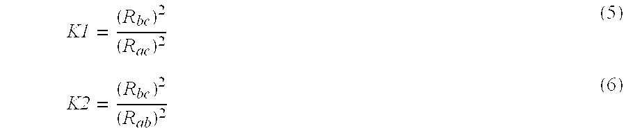
x=b/a (7)
Note that x is well defined because we assume that the none of the points in 3-space lies at the center of perspective, and hence “a” cannot be 0.
Then, the solutions of the system of equations 2-4 are given by the solutions to the quartic equation 8:
where
Once we have this solution, all the other points in the 3D model 100 can be moved by the same rigid motion, and projected through the camera transformation to the image. Even if we are using points from the 3D model 100 that gave rise to the 2D query 200, i.e. from the actual person whose picture we are trying to identify, the remaining points will in general not project precisely to their corresponding 2D points at this time. Due to errors in human placement of the points, roundoff errors, changes in the face over time, possibly an inaccurate camera model, lens distortion, and any number of other sources of error and noise, there will be some error in the 2D projection of these points.
Most of the time, we will be solving this problem for a 3D model which does not correctly identify the query. In that case, we would expect that the errors of the remaining points would be far greater than for the correct model.
However, there is another source of error. In many poses, some of the points that make up a triangle will be squashed together into a triangle that is extremely narrow. Under such conditions, the accuracy of the solution for the rigid transformation is subject to large numerical errors because very slight changes in the locations of the points under these conditions can lead to large changes in the rigid motion solution.
There is also the possibility that two candidate 3D models may be very similar, and if we choose the wrong triangles to use, the wrong model may win the remaining-point-error competition. To deal with these possibilities, we consider all the triples, and choose the rigid motion that results from the one with the least remaining-point error. Note that only the triangle enters into the calculation of the rigid motion. The other points only serve to choose among the 220 solutions corresponding to the 220 triangles we tried.
Although there are many reasonable and obvious choices for the “remaining-point error,” we are using the definition which is commonly known as square error, or “L2 error”:
In what follows, Rk denotes standard k-dimensional real Euclidean space. Assume we are using n points, i.e., n 3D points in correspondence with n 2D points. (In our examples, n=12.) Denote these points by the indices (1, 2, . . . , n). For each selected triple, renumber the points so that the selected triple consists of the points numbered 1, 2, and 3. Denote the points in the query by xi, where i is one of (1, 2, . . . , n). Note that xi is a point in R2. Similarly, denote the corresponding feature points in the 3D model as yi, where i is one of (1, 2, . . . , n) Note that yi is a point in R3. Denote the rigid motion of the model that was solved for by solving the perspective three point problem by T. Note that T is a map from R3 to R3, which we denote by:
Denote the perspective projection performed by the camera. Then the problem we have solved in the perspective three-point problem, recalling that the first three points after our renumbering are the ones that were matched, is:
The remaining-point error will depend on what happens to the remaining n-3 points, i.e., to the points (4, 5, . . . , n).
where ∥z∥ means the usual (Euclidean) norm in R2. To define this norm let z=(zx, zy), where zx is the x component of z, and zy is the y component of z. Note that here x and y stand for the axes of R2, unlike above and below, where we are using x and y as points in R2 and R3, respectively. Then the norm is defined by
Ei is known as the square error at point i.
The total square error, Etot, is then given by the sum of these quantities: 
Note that because the three triangle points i=(1,2,3) were solved to map exactly (up to root finding and machine roundoff error) to each other, so that the error at those points is already zero, this means we can, if we like, replace the above equation with: 
since Ei=0 for i=(1, 2, 3)
In the competition among the 220 solution sets (for n=12, i.e.) of up to four solutions each, that correspond to the 220 different choices for the triple of points used to solve the perspective 3 point problem, the winning solution is the one which achieves the lowest value of Etot.
Hand marked points can suffer from a certain amount of imprecision. This can arise from various sources, including resolution limitations of the devices being used to aid in the marking, as well as the fact that the features corresponding to the points being marked may not have perfectly well-defined locations in either the 3D model or the 2D query image. To compensate for these defects, the methods of the present invention contain an optional technique which attempts to find better points than the exact points presented to it in the data. This is done based on the assumption that the marked points obey a spherical Gaussian distribution with a mean at the “true” point position. I.e., if the true point position is at (u,v) in the query, then this module assumes that the probability that this point was actually marked at (x,y) is given by:
where A is a normalization factor, and s is the standard deviation, which is selected ad hoc, typically at about 1-3 pixel diameters. There are well-known techniques for generating random samples from such a distribution. The algorithm uses such a technique to generate a cloud of a small number of points around the data value (x,y). (The number of perturbed points to use in such a cloud is fixed for a given run of the algorithm. It can, however, be varied from query to query, but for each query, the number of points must be the same for all data points that are to be perturbed.) It does this by turning around the above distribution as a distribution of (u,v) values as a function of (x,y), i.e. it uses the distribution
which is identical to equation 21, except that we are now regarding this as a distribution of (u,v) with mean (x,y), to generate samples of (u,v) that might have been the “true” point locations. For example, if the number of perturbed points has been set to 4, we draw 4 consecutive samples from the distribution (equation 22), repeating this process successively at each data point (xi, yi) in the query. It then uses these extra points in the following way. Whenever a triple of points (p1, p2, p3) in 3D would have been matched with a triple of points (q1, q2, q3) in 2D, it first generates a Gaussian cloud of points around each of the qi.
Typically, there are about 3-10 points in a cloud. Suppose there are k points in a cloud. Then at each qi, the algorithm generates a cloud of points
Then, whenever qi appears in a triple of points that are to be used in a perspective three-point solution, not only is qi used in the solution, but each qij, for all j, is used for a solution as well. I.e., if the three 2D points are (q1, q2, q3), then all (q1j, q2j, q3j), where j takes on all values in (1, . . . , k), are used. I.e., First the solution is done using (q1, q2, q3). At each of (q1, q2, q3), a cloud of k points is generated. Then the solution is done using the j-th such cloud point in each cloud. This increases the cost of the algorithm by the constant factor (k+1).
In the example above where the number of perturbed points has been set to 4, we would draw 4 samples from the distribution at each data point qi, i.e., we would draw the samples:
q1,1, q1,2, q1,3, q1,4 from a distribution with mean at q1,
q2,1, q2,2, q2,3, q2,4 from a distribution with mean at q2,
q3,1, q3,2, q3,3, q3,4 from a distribution with mean at q3.
Note that each q is a point in 2-space.
Then, recalling we are computing a solution for the projection of (p1, p2, p3),
a solution would be computed for each of the correspondences:
(p i , p 2 , p 3)|→(q 1,2 , q 2,2 , q 3,2) (25)
A cost-saving variation of this procedure is to first solve for the pose of all triples without noise, i.e. solve using the unperturbed values of qi. Then, sort the triples used in this unperturbed stage based on the quality score. Finally, run the additional perturbed k triples for only the few best solutions. There is no need to add noise to triples that provided very bad quality scores in the first place, since it is very unlikely that such small perturbations will lead to large improvements in the quality.
The methods of the present invention have been implemented in the C programming language. The methods used to compute the solution of the perspective three point problem is the one presented in the RANSAC method. This reduces the problem to solving a quartic equation. The implementation uses a quartic equation solver available in the public domain on the internet.
The primary advantage over other methods is a better tradeoff between speed and robustness. The methods of the present invention are both extremely fast and quite robust.
The methods of the present invention are particularly well suited to the application, where a small number of manually marked points with known correspondences must be used to find pose.
It does not require knowledge of a camera model, since it is robust enough that it works with a “typical” camera model, and it also does not need to solve for a camera model.
Although the code to solve a quartic is somewhat complex, this is a well-understood area. Because the methods of the present invention use the quartic solution, they are in other respects simpler than most approaches, since no heuristics are required, and no iterative solutions are required.
The methods of the present invention will now be summarized with reference to the flowcharts of FIGS. 7, 8, 9 a, and 9 b in which like reference numerals indicate like or similar steps. Referring now to the flowchart of FIG. 7, the method of the present invention comprises marking a predetermined number of feature points, typically by a human operator, on both a 3D model and a 2D query image at steps 702 and 704, respectively. Preferably the number of feature points chosen is in the range of 8-12. At step 706, all subsets of three pairs of corresponding feature points are generated. Given each subset of three feature points in three-dimensional space, and three corresponding feature points in two-dimensional space, the four possible three-dimensional rigid motions of the three points in three-dimensional space are computed at step 708, such that after each of these four rigid motions, a fixed perspective projection maps the three three-dimensional points precisely to the three corresponding two-dimensional points. Step 708 is then repeated for all possible subsets of three two-dimensional points marked in the query. For each solution found in step 708, an error measure is computed at step 710 which is derived from the errors in the projections of all three-dimensional marked points in the model which were not among the three points used in that solution, but which did have corresponding marked points in the two-dimensional query. At step 712, the solutions are ranked based on the error computed at step 710. Lastly, at step 714 the best solution is selected based on the ranking of step 712.
Referring now to the flowchart of FIG. 8, a first variation of the previously described method is summarized. In the first variation of the methods of the present invention, steps 702, 704, and 706 are carried out as in the method discussed above. At step 802, a small number, about 10, perturbed points are computed which are derived from each of the original feature points. These points are typically obtained by sampling from a spherical Gaussian distribution. Step 804 is similar to step 708 discussed above with regard to the above method, except that the computation is also carried out for the corresponding perturbed points from step 802. For each solution found in step 804, an error measure is computed at step 710 which is derived from the errors in the projections of all three-dimensional marked points in the model which were not among the three points used in that solution, but which did have corresponding marked points in the two-dimensional query. At step 712, the solutions are ranked based on the error computed at step 710. Lastly, at step 714 the best solution is selected based on the ranking of step 712.
Referring now to the flowcharts of FIGS. 9a and 9 b, a second variation of the methods of the present invention will be summarized. The second variation of the methods of the present invention starts with the same steps 702, 704, 706, 708, 710, and 712 as the method described above with regard to FIG. 7. However, instead of step 714, where the best solution is selected based on the ranking of step 712, a subset of the most promising solutions are selected at step 902 based on the ranking of step 712. Similar to step 802 described above with regard to the first variation of the methods of the present invention, a small number, about 10, of perturbed points are computed at step 904 which are derived from each of the original feature points which are members of promising subset. Unlike step 802, only the “promising” subset of point-pair triples are used. At step 906, the computation of step 804 is carried out on the corresponding perturbed points from step 904. At step 908, for each solution found in step 906, an error measure is computed which is derived from the errors in the projections of the corresponding perturbed three-dimensional marked points in the model which were not among the three points used in that solution, but which did have corresponding marked points in the two-dimensional query. At step 910, the solutions from steps 708 and 906 are ranked based on the error computed in steps 710 and 908. Lastly, at step 714, best solution is selected based on the ranking of step 910.
While there has been shown and described what is considered to be preferred embodiments of the invention, it will, of course, be understood that various modifications and changes in form or detail could readily be made without departing from the spirit of the invention. It is therefore intended that the invention be not limited to the exact forms described and illustrated, but should be constructed to cover all modifications that may fall within the scope of the appended claims.
Claims (24)
1. A method for computing the location and orientation of an object in three-dimensional space, the method comprising the steps of:
(a) marking a plurality of feature points on a three-dimensional model and corresponding feature points on a two-dimensional query image;
(b) for all possible subsets of three two-dimensional feature points marked in step (a), computing the four possible three-dimensional rigid motion solutions of a set of three points in three-dimensional space such that after each of the four rigid motions, under a fixed perspective projection, the three three-dimensional points are mapped precisely to the three corresponding two-dimensional points;
(c) for each solution found in step (b), computing an error measure derived from the errors in the projections of all three-dimensional marked points in the three-dimensional model which were not among the three points used in the solution, but which did have corresponding marked points in the two-dimensional query image;
(d) ranking the solutions from step (c) based on the computed error measure; and
(e) selecting the best solution based on the ranking in step (d).
2. The method of claim 1 , wherein the number of feature points marked in step (a) is in the range of 8-12.
3. The method of claim 1 , further comprising, after step (a), the step of computing a predetermined number of perturbed points derived from each of the feature points wherein the computation of step (b) is on all possible subsets of three two-dimensional points marked in the query image, and in addition on the corresponding perturbed points.
4. The method of claim 3 , wherein the predetermined number of perturbed points are obtained by sampling from a spherical Gaussian distribution.
5. The method of claim 1 , after step (d), further comprising the steps of:
(i) choosing a subset of the solutions from step (c) based on the ranking of step (d);
(ii) computing a predetermined number of perturbed points derived from each of the subset of the solutions;
(iii) repeating step (b) on the predetermined number of perturbed points; and
(iv) repeating step (c) for each solution found in step (iii);
wherein the ranking of step (d) is based on the error computed in both steps (c) and (iv).
6. The method of claim 5 , wherein the subset of solutions chosen is a predetermined portion of the ranked solutions.
7. The method of claim 6 , wherein the predetermined portion is the top 10% of the ranked solutions.
8. The method of claim 5 , wherein the predetermined number of perturbed points are obtained by sampling from a spherical Gaussian distribution.
9. A computer program product embodied in a computer-readable medium for computing the location and orientation of an object in three-dimensional space, the computer program product comprising:
(a) computer readable program code means for marking a plurality of feature points on a three-dimensional model and corresponding feature points on a two-dimensional query image;
(b) computer readable program code means for computing, for all possible subsets of three two-dimensional feature points marked, the four possible three-dimensional rigid motion solutions of a set of three points in three-dimensional space such that after each of the four rigid motions, under a fixed perspective projection, the three three-dimensional points are mapped precisely to the three corresponding two-dimensional points;
(c) computer readable program code means for computing, for each solution, an error measure derived from the errors in the projections of all three-dimensional marked points in the three-dimensional model which were not among the three points used in the solution, but which did have corresponding marked points in the two-dimensional query image;
(d) computer readable program code means for ranking the solutions based on the computed error measure; and
(e) computer readable program code means for selecting the best solution based on the ranking.
10. The computer program product of claim 9 , wherein the number of feature points marked is in the range of 8-12.
11. The computer program product of claim 9 , further comprising computer readable program code means for computing a predetermined number of perturbed points derived from each of the feature points wherein the computation in (b) is on all possible subsets of three two-dimensional points marked in the query image, and in addition on the corresponding perturbed points.
12. The computer program product of claim 11 , wherein the predetermined number of perturbed points are obtained by sampling from a spherical Gaussian distribution.
13. The computer program product of claim 9 , further comprising:
(i) computer readable program code means for choosing a subset of the solutions from (c) based on the ranking of (d);
(ii) computer readable program code means for computing a predetermined number of perturbed points derived from each of the subset of the solutions;
(iii) computer readable program code means for repeating (b) on the predetermined number of perturbed points; and
(iv) computer readable program code means for repeating (c) for each solution found in (iii);
wherein the ranking of (d) is based on the error computed in both (c) and (iv).
14. The computer program product of claim 13 , wherein the subset of solutions chosen is a predetermined portion of the ranked solutions.
15. The computer program product of claim 14 , wherein the predetermined portion is the top 10% of the ranked solutions.
16. The computer program product of claim 13 , wherein the predetermined number of perturbed points are obtained by sampling from a spherical Gaussian distribution.
17. A program storage device readable by machine, tangibly embodying a program of instructions executable by the machine to perform method steps for computing the location and orientation of an object in three-dimensional space, the method comprising the steps of:
(a) marking a plurality of feature points on a three-dimensional model and corresponding feature points on a two-dimensional query image;
(b) for all possible subsets of three two-dimensional feature points marked in step (a), computing the four possible three-dimensional rigid motion solutions of a set of three points in three-dimensional space such that after each of the four rigid motions, under a fixed perspective projection, the three three-dimensional points are mapped precisely to the three corresponding two-dimensional points;
(c) for each solution found in step (b), computing an error measure derived from the errors in the projections of all three-dimensional marked points in the three-dimensional model which were not among the three points used in the solution, but which did have corresponding marked points in the two-dimensional query image;
(d) ranking the solutions from step (c) based on the computed error measure; and
(e) selecting the best solution based on the ranking in step (d).
18. The method of claim 17 , wherein the number of feature points marked in step (a) is in the range of 8-12.
19. The method of claim 17 , further comprising, after step (a), the step of computing a predetermined number of perturbed points derived from each of the feature points wherein the computation of step (b) is on all possible subsets of three two-dimensional points marked in the query image, and in addition on the corresponding perturbed points.
20. The method of claim 19 , wherein the predetermined number of perturbed points are obtained by sampling from a spherical Gaussian distribution.
21. The method of claim 17 , after step (d), further comprising the steps of:
(i) choosing a subset of the solutions from step (c) based on the ranking of step (d);
(ii) computing a predetermined number of perturbed points derived from each of the subset of the solutions;
(iii) repeating step (b) on the predetermined number of perturbed points; and
(iv) repeating step (c) for each solution found in step (iii);
wherein the ranking of step (d) is based on the error computed in both steps (c) and (iv).
22. The method of claim 21 , wherein the subset of solutions chosen is a predetermined portion of the ranked solutions.
23. The method of claim 22 , wherein the predetermined portion is the top 10% of the ranked solutions.
24. The method of claim 21 , wherein the predetermined number of perturbed points are obtained by sampling from a spherical Gaussian distribution.
Priority Applications (4)
| Application Number | Priority Date | Filing Date | Title |
|---|---|---|---|
| US09/538,208 US6580821B1 (en) | 2000-03-30 | 2000-03-30 | Method for computing the location and orientation of an object in three dimensional space |
| JP2000257304A JP2001283229A (en) | 2000-03-30 | 2000-08-28 | Method for calculating position and direction of object in three-dimensional space |
| DE60023447T DE60023447T2 (en) | 2000-03-30 | 2000-08-30 | METHOD FOR CALCULATING THE POSITION AND ORIENTATION OF AN OBJECT IN THREE-DIMENSIONAL SPACES |
| EP00118165A EP1139270B1 (en) | 2000-03-30 | 2000-08-30 | Method for computing the location and orientation of an object in three-dimensional space |
Applications Claiming Priority (1)
| Application Number | Priority Date | Filing Date | Title |
|---|---|---|---|
| US09/538,208 US6580821B1 (en) | 2000-03-30 | 2000-03-30 | Method for computing the location and orientation of an object in three dimensional space |
Publications (1)
| Publication Number | Publication Date |
|---|---|
| US6580821B1 true US6580821B1 (en) | 2003-06-17 |
Family
ID=24145948
Family Applications (1)
| Application Number | Title | Priority Date | Filing Date |
|---|---|---|---|
| US09/538,208 Expired - Lifetime US6580821B1 (en) | 2000-03-30 | 2000-03-30 | Method for computing the location and orientation of an object in three dimensional space |
Country Status (4)
| Country | Link |
|---|---|
| US (1) | US6580821B1 (en) |
| EP (1) | EP1139270B1 (en) |
| JP (1) | JP2001283229A (en) |
| DE (1) | DE60023447T2 (en) |
Cited By (65)
| Publication number | Priority date | Publication date | Assignee | Title |
|---|---|---|---|---|
| US20020018062A1 (en) * | 2000-08-11 | 2002-02-14 | Minolta Co., Ltd. | Method and apparatus for generating three-dimensional data |
| US20020102010A1 (en) * | 2000-12-06 | 2002-08-01 | Zicheng Liu | System and method providing improved head motion estimations for animation |
| US20020176627A1 (en) * | 2001-03-28 | 2002-11-28 | Nec Corporation | Pattern-collating device, pattern-collating method and pattern-collating program |
| US20030035098A1 (en) * | 2001-08-10 | 2003-02-20 | Nec Corporation | Pose estimation method and apparatus |
| US20030063586A1 (en) * | 2001-09-28 | 2003-04-03 | Engholm Kathryn A. | Visualization of active codes, their spreading factors and power levels, in a code domain power display |
| US20030137510A1 (en) * | 2000-05-27 | 2003-07-24 | Robert Massen | Method and assembly for the photogrammetric detection of the 3-d shape of an object |
| US20030206171A1 (en) * | 2002-05-03 | 2003-11-06 | Samsung Electronics Co., Ltd. | Apparatus and method for creating three-dimensional caricature |
| US6714214B1 (en) | 1999-12-07 | 2004-03-30 | Microsoft Corporation | System method and user interface for active reading of electronic content |
| US20040114481A1 (en) * | 2002-09-02 | 2004-06-17 | Samsung Electronics Co., Ltd. | Optical information storage medium and method of and apparatus for recording and/or reproducing information on and/or from the optical information storage medium |
| US20040119848A1 (en) * | 2002-11-12 | 2004-06-24 | Buehler Christopher J. | Method and apparatus for computerized image background analysis |
| US20040130620A1 (en) * | 2002-11-12 | 2004-07-08 | Buehler Christopher J. | Method and system for tracking and behavioral monitoring of multiple objects moving through multiple fields-of-view |
| US20040227820A1 (en) * | 2003-03-11 | 2004-11-18 | David Nister | Method and apparatus for determining camera pose from point correspondences |
| US20050046626A1 (en) * | 2003-09-02 | 2005-03-03 | Fuji Photo Film Co., Ltd. | Image generating apparatus, image generating method and image generating program |
| US20050047630A1 (en) * | 2000-03-09 | 2005-03-03 | Microsoft Corporation | Rapid computer modeling of faces for animation |
| US20050058321A1 (en) * | 2003-09-11 | 2005-03-17 | Buehler Christopher J. | Computerized method and apparatus for determining field-of-view relationships among multiple image sensors |
| US20050078852A1 (en) * | 2003-10-10 | 2005-04-14 | Buehler Christopher J. | Method of counting objects in a monitored environment and apparatus for the same |
| US20050078853A1 (en) * | 2003-10-10 | 2005-04-14 | Buehler Christopher J. | System and method for searching for changes in surveillance video |
| US20060176301A1 (en) * | 2005-02-07 | 2006-08-10 | Samsung Electronics Co., Ltd. | Apparatus and method of creating 3D shape and computer-readable recording medium storing computer program for executing the method |
| US7113641B1 (en) * | 1998-08-14 | 2006-09-26 | Christian Eckes | Method for recognizing objects in digitized images |
| US20060233423A1 (en) * | 2005-04-19 | 2006-10-19 | Hesam Najafi | Fast object detection for augmented reality systems |
| US20070052698A1 (en) * | 2003-07-11 | 2007-03-08 | Ryuji Funayama | Image processing apparatus, image processing method, image processing program, and recording medium |
| US20070075996A1 (en) * | 2005-10-03 | 2007-04-05 | Konica Minolta Holdings, Inc. | Modeling system, and modeling method and program |
| US20070179377A1 (en) * | 2003-12-11 | 2007-08-02 | Koninklijke Philips Electronic, N.V. | Elastic image registration |
| US20070183662A1 (en) * | 2006-02-07 | 2007-08-09 | Haohong Wang | Inter-mode region-of-interest video object segmentation |
| US20070183661A1 (en) * | 2006-02-07 | 2007-08-09 | El-Maleh Khaled H | Multi-mode region-of-interest video object segmentation |
| US20070182818A1 (en) * | 2005-09-02 | 2007-08-09 | Buehler Christopher J | Object tracking and alerts |
| US20070183665A1 (en) * | 2006-02-06 | 2007-08-09 | Mayumi Yuasa | Face feature point detecting device and method |
| US20070183663A1 (en) * | 2006-02-07 | 2007-08-09 | Haohong Wang | Intra-mode region-of-interest video object segmentation |
| US20070201729A1 (en) * | 2006-02-06 | 2007-08-30 | Mayumi Yuasa | Face feature point detection device and method |
| US20070211944A1 (en) * | 2006-03-07 | 2007-09-13 | Tomoyuki Takeguchi | Apparatus for detecting feature point and method of detecting feature point |
| US20070274574A1 (en) * | 2004-08-20 | 2007-11-29 | Boult Terrance E | Biometric signatures and identification through the use of projective invariants |
| US20070283004A1 (en) * | 2006-06-02 | 2007-12-06 | Buehler Christopher J | Systems and methods for distributed monitoring of remote sites |
| US20070288141A1 (en) * | 2004-06-22 | 2007-12-13 | Bergen James R | Method and apparatus for visual odometry |
| US20080181486A1 (en) * | 2007-01-26 | 2008-07-31 | Conversion Works, Inc. | Methodology for 3d scene reconstruction from 2d image sequences |
| WO2008112786A2 (en) * | 2007-03-12 | 2008-09-18 | Conversion Works, Inc. | Systems and method for generating 3-d geometry using points from image sequences |
| US20080240518A1 (en) * | 2007-03-30 | 2008-10-02 | Sony United Kingdom Limited | Apparatus and method of image capture |
| US20080303902A1 (en) * | 2007-06-09 | 2008-12-11 | Sensomatic Electronics Corporation | System and method for integrating video analytics and data analytics/mining |
| US20090096790A1 (en) * | 2007-10-11 | 2009-04-16 | Mvtec Software Gmbh | System and method for 3d object recognition |
| US20090131836A1 (en) * | 2007-03-06 | 2009-05-21 | Enohara Takaaki | Suspicious behavior detection system and method |
| US20090245624A1 (en) * | 2002-07-10 | 2009-10-01 | Nec Corporation | Image matching system using three-dimensional object model, image matching method, and image matching program |
| US20100002082A1 (en) * | 2005-03-25 | 2010-01-07 | Buehler Christopher J | Intelligent camera selection and object tracking |
| US7671728B2 (en) | 2006-06-02 | 2010-03-02 | Sensormatic Electronics, LLC | Systems and methods for distributed monitoring of remote sites |
| CN101807247A (en) * | 2010-03-22 | 2010-08-18 | 中国农业大学 | Fine-adjustment positioning method of fruit and vegetable picking point |
| US20100322535A1 (en) * | 2009-06-22 | 2010-12-23 | Chunghwa Picture Tubes, Ltd. | Image transformation method adapted to computer program product and image display device |
| US20110153210A1 (en) * | 2009-12-22 | 2011-06-23 | General Electric Company | Relative Navigation System and a Method Thereof |
| US20110153205A1 (en) * | 2009-12-22 | 2011-06-23 | General Electric Company | Relative Navigation System |
| US20110153211A1 (en) * | 2009-12-22 | 2011-06-23 | General Electric Company | Method of determining range |
| US20110227924A1 (en) * | 2010-03-17 | 2011-09-22 | Casio Computer Co., Ltd. | 3d modeling apparatus, 3d modeling method, and computer readable medium |
| US20110234759A1 (en) * | 2010-03-29 | 2011-09-29 | Casio Computer Co., Ltd. | 3d modeling apparatus, 3d modeling method, and computer readable medium |
| US20120114175A1 (en) * | 2010-11-05 | 2012-05-10 | Samsung Electronics Co., Ltd. | Object pose recognition apparatus and object pose recognition method using the same |
| US20130121598A1 (en) * | 2011-11-15 | 2013-05-16 | Futurewei Technologies, Inc. | System and Method for Randomized Point Set Geometry Verification for Image Identification |
| CN103295025A (en) * | 2013-05-03 | 2013-09-11 | 南京大学 | Automatic selecting method of three-dimensional model optimal view |
| US20130243278A1 (en) * | 2012-03-19 | 2013-09-19 | Hiroo SAITO | Biological information processor |
| CN103366158A (en) * | 2013-06-27 | 2013-10-23 | 东南大学 | Three dimensional structure and color model-based monocular visual road face detection method |
| US8791941B2 (en) | 2007-03-12 | 2014-07-29 | Intellectual Discovery Co., Ltd. | Systems and methods for 2-D to 3-D image conversion using mask to model, or model to mask, conversion |
| US8830229B2 (en) | 2010-05-07 | 2014-09-09 | Mvtec Software Gmbh | Recognition and pose determination of 3D objects in 3D scenes |
| US8860712B2 (en) | 2004-09-23 | 2014-10-14 | Intellectual Discovery Co., Ltd. | System and method for processing video images |
| CN104182765A (en) * | 2014-08-21 | 2014-12-03 | 南京大学 | Internet image driven automatic selection method of optimal view of three-dimensional model |
| CN104778731A (en) * | 2015-03-03 | 2015-07-15 | 北京空间机电研究所 | Method for solving three-dimensional similarity transformation parameter of model based on fitting plane normal vector direction |
| CN104867156A (en) * | 2015-06-01 | 2015-08-26 | 中国科学院光电技术研究所 | Feature point identification method aiming at pose measuring of cooperation marker |
| US20150348269A1 (en) * | 2014-05-27 | 2015-12-03 | Microsoft Corporation | Object orientation estimation |
| US20170228929A1 (en) * | 2015-09-01 | 2017-08-10 | Patrick Dengler | System and Method by which combining computer hardware device sensor readings and a camera, provides the best, unencumbered Augmented Reality experience that enables real world objects to be transferred into any digital space, with context, and with contextual relationships. |
| US9868212B1 (en) * | 2016-02-18 | 2018-01-16 | X Development Llc | Methods and apparatus for determining the pose of an object based on point cloud data |
| US10878657B2 (en) | 2018-07-25 | 2020-12-29 | Konami Gaming, Inc. | Casino management system with a patron facial recognition system and methods of operating same |
| US11521460B2 (en) | 2018-07-25 | 2022-12-06 | Konami Gaming, Inc. | Casino management system with a patron facial recognition system and methods of operating same |
Families Citing this family (29)
| Publication number | Priority date | Publication date | Assignee | Title |
|---|---|---|---|---|
| US20030123734A1 (en) * | 2001-12-28 | 2003-07-03 | Koninklijke Philips Electronics N.V. | Methods and apparatus for object recognition |
| AUPS170902A0 (en) | 2002-04-12 | 2002-05-16 | Canon Kabushiki Kaisha | Face detection and tracking in a video sequence |
| AU2003203644B2 (en) * | 2002-04-12 | 2005-10-06 | Canon Kabushiki Kaisha | Face detection and tracking in a video sequence |
| US7706601B2 (en) | 2003-08-29 | 2010-04-27 | Nec Corporation | Object posture estimation/correlation system using weight information |
| US7593550B2 (en) | 2005-01-26 | 2009-09-22 | Honeywell International Inc. | Distance iris recognition |
| US8442276B2 (en) | 2006-03-03 | 2013-05-14 | Honeywell International Inc. | Invariant radial iris segmentation |
| US8705808B2 (en) | 2003-09-05 | 2014-04-22 | Honeywell International Inc. | Combined face and iris recognition system |
| US8049812B2 (en) | 2006-03-03 | 2011-11-01 | Honeywell International Inc. | Camera with auto focus capability |
| US8064647B2 (en) | 2006-03-03 | 2011-11-22 | Honeywell International Inc. | System for iris detection tracking and recognition at a distance |
| US8090157B2 (en) * | 2005-01-26 | 2012-01-03 | Honeywell International Inc. | Approaches and apparatus for eye detection in a digital image |
| US8098901B2 (en) | 2005-01-26 | 2012-01-17 | Honeywell International Inc. | Standoff iris recognition system |
| KR100816607B1 (en) | 2003-10-21 | 2008-03-24 | 닛본 덴끼 가부시끼가이샤 | Image collation system and image collation method |
| GB2448653B (en) | 2006-03-03 | 2011-03-23 | Honeywell Int Inc | Single lens splitter camera |
| KR101299074B1 (en) | 2006-03-03 | 2013-08-30 | 허니웰 인터내셔널 인코포레이티드 | Iris encoding system |
| JP4738488B2 (en) | 2006-03-03 | 2011-08-03 | ハネウェル・インターナショナル・インコーポレーテッド | Iris recognition system with image quality metric |
| GB2450024B (en) | 2006-03-03 | 2011-07-27 | Honeywell Int Inc | Modular biometrics collection system architecture |
| CN101542520B (en) * | 2007-03-09 | 2011-12-07 | 欧姆龙株式会社 | Recognition processing method and image processing device using the same |
| US8063889B2 (en) | 2007-04-25 | 2011-11-22 | Honeywell International Inc. | Biometric data collection system |
| US8436907B2 (en) | 2008-05-09 | 2013-05-07 | Honeywell International Inc. | Heterogeneous video capturing system |
| US8090246B2 (en) | 2008-08-08 | 2012-01-03 | Honeywell International Inc. | Image acquisition system |
| US8280119B2 (en) | 2008-12-05 | 2012-10-02 | Honeywell International Inc. | Iris recognition system using quality metrics |
| US8472681B2 (en) | 2009-06-15 | 2013-06-25 | Honeywell International Inc. | Iris and ocular recognition system using trace transforms |
| US8630464B2 (en) | 2009-06-15 | 2014-01-14 | Honeywell International Inc. | Adaptive iris matching using database indexing |
| CN101719264B (en) * | 2009-12-28 | 2012-05-23 | 清华大学 | Method for computing visual field of multi-view dynamic scene acquisition |
| US8742887B2 (en) | 2010-09-03 | 2014-06-03 | Honeywell International Inc. | Biometric visitor check system |
| DE102014005181A1 (en) | 2014-04-03 | 2015-10-08 | Astrium Gmbh | Position and orientation of objects |
| EP4217916A1 (en) * | 2020-09-28 | 2023-08-02 | BAE SYSTEMS plc | Large space tracking using a wearable optics device |
| EP3975040A1 (en) * | 2020-09-28 | 2022-03-30 | BAE SYSTEMS plc | Large space tracking using a wearable optics device |
| CN112907671B (en) * | 2021-03-31 | 2022-08-02 | 深圳市慧鲤科技有限公司 | Point cloud data generation method and device, electronic equipment and storage medium |
Citations (4)
| Publication number | Priority date | Publication date | Assignee | Title |
|---|---|---|---|---|
| US4860216A (en) * | 1986-11-13 | 1989-08-22 | The United States Of America As Represented By The Secretary Of The Air Force | Communication adaptive multi-sensor system |
| US4975969A (en) * | 1987-10-22 | 1990-12-04 | Peter Tal | Method and apparatus for uniquely identifying individuals by particular physical characteristics and security system utilizing the same |
| US6243488B1 (en) * | 1993-08-05 | 2001-06-05 | U.S. Philips Corporation | Method and apparatus for rendering a two dimensional image from three dimensional image data |
| US6434278B1 (en) * | 1997-09-23 | 2002-08-13 | Enroute, Inc. | Generating three-dimensional models of objects defined by two-dimensional image data |
-
2000
- 2000-03-30 US US09/538,208 patent/US6580821B1/en not_active Expired - Lifetime
- 2000-08-28 JP JP2000257304A patent/JP2001283229A/en active Pending
- 2000-08-30 DE DE60023447T patent/DE60023447T2/en not_active Expired - Lifetime
- 2000-08-30 EP EP00118165A patent/EP1139270B1/en not_active Expired - Lifetime
Patent Citations (4)
| Publication number | Priority date | Publication date | Assignee | Title |
|---|---|---|---|---|
| US4860216A (en) * | 1986-11-13 | 1989-08-22 | The United States Of America As Represented By The Secretary Of The Air Force | Communication adaptive multi-sensor system |
| US4975969A (en) * | 1987-10-22 | 1990-12-04 | Peter Tal | Method and apparatus for uniquely identifying individuals by particular physical characteristics and security system utilizing the same |
| US6243488B1 (en) * | 1993-08-05 | 2001-06-05 | U.S. Philips Corporation | Method and apparatus for rendering a two dimensional image from three dimensional image data |
| US6434278B1 (en) * | 1997-09-23 | 2002-08-13 | Enroute, Inc. | Generating three-dimensional models of objects defined by two-dimensional image data |
Non-Patent Citations (51)
| Title |
|---|
| A. Shashua, "Geometry and Photometry in 3D Visual Recognition", Massachusetts Institute of Technology, 1992, pp. 1-165. |
| A.R. Brooks, "Symbolic Reasoning Among 3-D Models and 2-D Images", Dissertation 1981, pp. 1-172. |
| A.S. Georghiades et al., "Illumination Cones for Recognition Under Variable Lighting: Faces", To appear in the Proceedings of CVPR98. |
| B.K.P. Horn et al., "Calculating the reflectance map", Applied Optics, 1979, pp. 1770-1779. |
| B.K.P. Horn et al., "Calculating The Reflectance Map", Artificial Intelligence Laboratory, pp. 115-126. |
| B.K.P. Horn, "Hill-Shading and the Reflectance Map", Artificial Intelligence Laboratory, pp. 79-120. |
| B.K.P. Horn, "Hill-Shading and the Reflectance Map", Proceedings of the IEEE, vol. 69, 1981, pp. 14-47. |
| B.K.P. Horn, "Shape From Shading: A Method For Obtaining The Shape Of A Smooth Opaque Object From One View", Massachusetts Institute of Technology, 1970, pp. 1-197. |
| B.K.P. Horn, "Understanding Image Intensities", Artificial Intelligence 8, 1977, pp. 201-231. |
| D.G. Lowe, "Fitting Parameterized Three-Dimensional Models to Images", IEEE Transactions on Pattern Analysis and Machine Intelligence, 1991, pp. 441-450. |
| D.G. Lowe, "Three-Dimensional Object Recognition from Single Two-Dimensional Images", 1987, pp. 355-395. |
| D.G. Lowe, "Visual Recognition From Spatial Correspondence And Perceptual Organization", pp. 953-959. |
| D.P. Huttenlocher et al., "Object Recognition Using Alignment", DARPA Image Understanding Workshop, 1987, pp. 370-379. |
| D.P. Huttenlocher et al., "Object Recognition Using Alignment", IEEE, 1987, pp. 102-111. |
| D.P. Huttenlocher et al., "Recognizing Solid Objects by Alignment with an Image", International Journal of Computer Vision, 1990, pp. 195-212. |
| D.P. Huttenlocher et al., "Recognizing Solid Objects by Alignment", DARPA Image Understanding Workshop, 1998, pp. 1114-1122. |
| D.P. Huttenlocher, "Three-Dimensional Recognition of Solid Objects from a Two-Dimensional Image", MIT Artificial Laboratory, Technical Report 1045, 1988, pp. 1-161. |
| Fischler et al., Random Sample Consensus: A Paradigm for Model Fitting with Applications to Image Analysis and Automated Cartography, 1981, SRI International 1981, 391-395.* * |
| Huttenlocher et al., Recognizing Solid Objects by Alignment with an Image, 1990, Internal Jouranl of Computer Vision, Kluwer Academic Publishers, 5:2, 195-212.* * |
| J. Olienis et al., "A Global Algorithm for Shape from Shading", IEEE, 1993, pp. 692-701. |
| J. Olienis et al., "Provably Convergent Algorithms for Shape from Shading", Image Understanding Workshop, 1993, pp. 1121-1130. |
| J. Olienis, "Existence and Uniqueness in Shape from Shading", IEEE, 1990, pp. 341-345. |
| J. Olienis, "New Results In Shape From Shading", Image Understanding Workshop, 1990, pp. 145-153. |
| J. Olienis, "Shape from Shading as a Partially Well-Constrained Problem", CVGIP 1991, pp. 163-183. |
| J. Olienis, "Shape from Shading as a Partially Well-Constrained Problem", IEEE, 1991, pp. 559-564. |
| J. Olienis, "Uniqueness in Shape from Shading", International Journal of Computer Vision, 1991, pp. 75-104. |
| J. Oliensis et al., "Direct method for reconstructing shape from shading", SPIE, 1991, pp. 116-128. |
| J.J. Koenderink et al., "Photometric invariants related to solid shape", OPTICA ACTA, 1980, pp. 981-996. |
| L. Sirovich et al., "Low-dimensional procedure for the characterization of human faces", Optical Society of America, 1987, pp. 519-524. |
| L. Wiskott et al., "Face Recognition by Elastic Bunch Graph Matching", IEEE Transactions on Pattern Analysis and Machine Intelligence, vol. 19, 1997, pp. 775-779. |
| L.G. Roberts, "Machine Perception of Three-Dimensional Solids", Massachusetts Institute of Technology Lincoln Laboratory, Technical Report No. 315, 1965, pp. 1-40. |
| M. Kirby et al., "Application of the Karhunen-Loeve Procedure for the Characterization of Human Faces", IEEE, 1990, pp. 103-108. |
| M. Turk et al., Eigenfaces for Recognition:, Journal of Cognitive Neurosocience, vol. 3, No. 1, 1991, pp. 71-86. |
| M.A. Fischler et al., "Random Sample Consensus: A Paradigm for Model Fitting with Application to Image Analysis and Automated Cartography", SRI International 1981, pp. 381-395. |
| M.A. Turk et al., "Face Recognition Using Eigenfaces", IEEE, 1991, pp. 586-591. |
| P. Dupuis et al., "Direct Method for Reconstructing Shape From Shading", DARPA Image Understand, 1992, pp. 563-571. |
| P. Dupuis et al., "Direct Method For Reconstructing Shape From Shading", IEEE 1992, pp. 453-458. |
| P. Viola et al., "Alignment by Maximization of Mutual Information", To appear at the International Conference on Computer Vision, 1995. |
| P.H. Winston, "Obtaining Shape From Shading Information", The Psychology of Computer Vision, pp. 115-155. |
| P.N. Belhumeur et al., "Comparing Images Under Variable Illumination", To appear in the Proceedings of CVPR98. |
| P.N. Belhumeur et al., "What Is the Set of Images of an Object under All Possible Illumination Conditions?", International Journal of Computer Vision, 1998, pp. 1-16. |
| P.N. Belhumuer et al., "The Bas-Relief Ambiguity", In the Proceedings of CVPR97. |
| P.S. Penev, "Local Feature Analysis: A general statistical theory for object representation", 1996, pp. 1-27. |
| R. Zurmuhl, "Praktische Mathematik", Springer-Verlag, 1965, pp. 60-65. |
| R.A. Brooks et al., "The AGRONYM Model-Based Vision System", Proceedings of the Sixth International Joint Conference on Artificial Intelligence, 1979, pp. 105-113. |
| R.A. Brooks, "Model-Based Three-Dimensional Interpretations of Two-Dimensional Images", IEEE Transactions on Pattern Analysis and Machine Intelligence, 1983, pp. 140-150. |
| R.A. Brooks, "Symbolic Reasoning Among 3-D Models and 2-D Images", Artificial Intelligence 17, 1981, pp. 285-345. |
| S. Ullman et al., "Recognition by Linear Combinations of Models", IEEE, 1991, pp. 992-1006. |
| T. Vetter et al., "Estimating Coloured 3D Face Models from Single Images: An Example Based Approach", European Conference on Computer Vision vol. 2, pp. 499-512. |
| T. Vetter, "Synthesis of novel views from a single face image", Max-Planck-Institute Technical Report No. 26, 1996, pp. 1-13. |
| W.E.L. Grimson et al., "On the Verification of Hypothesized Matches in Model-Based Recognition", IEEE Transactions on Pattern Analysis and Machine Intelligence, 1991, pp. 1201-1213. |
Cited By (149)
| Publication number | Priority date | Publication date | Assignee | Title |
|---|---|---|---|---|
| US7113641B1 (en) * | 1998-08-14 | 2006-09-26 | Christian Eckes | Method for recognizing objects in digitized images |
| US6714214B1 (en) | 1999-12-07 | 2004-03-30 | Microsoft Corporation | System method and user interface for active reading of electronic content |
| US7133540B2 (en) | 2000-03-09 | 2006-11-07 | Microsoft Corporation | Rapid computer modeling of faces for animation |
| US20050213820A1 (en) * | 2000-03-09 | 2005-09-29 | Microsoft Corporation | Rapid computer modeling of faces for animation |
| US7181051B2 (en) * | 2000-03-09 | 2007-02-20 | Microsoft Corporation | Rapid computer modeling of faces for animation |
| US20060104491A1 (en) * | 2000-03-09 | 2006-05-18 | Microsoft Corporation | Rapid Computer Modeling of Faces for Animation |
| US7174035B2 (en) | 2000-03-09 | 2007-02-06 | Microsoft Corporation | Rapid computer modeling of faces for animation |
| US20060104490A1 (en) * | 2000-03-09 | 2006-05-18 | Microsoft Corporation | Rapid Computer Modeling of Faces for Animation |
| US7158658B2 (en) | 2000-03-09 | 2007-01-02 | Microsoft Corporation | Rapid computer modeling of faces for animation |
| US7149330B2 (en) | 2000-03-09 | 2006-12-12 | Microsoft Corporation | Rapid computer modeling of faces for animation |
| US7149329B2 (en) | 2000-03-09 | 2006-12-12 | Microsoft Corporation | Rapid computer modeling of faces for animation |
| US7142698B2 (en) | 2000-03-09 | 2006-11-28 | Microsoft Corporation | Rapid computer modeling of faces for animation |
| US20050207623A1 (en) * | 2000-03-09 | 2005-09-22 | Microsoft Corporation | Rapid computer modeling of faces for animation |
| US7212656B2 (en) | 2000-03-09 | 2007-05-01 | Microsoft Corporation | Rapid computer modeling of faces for animation |
| US7082212B2 (en) | 2000-03-09 | 2006-07-25 | Microsoft Corporation | Rapid computer modeling of faces for animation |
| US20050053277A1 (en) * | 2000-03-09 | 2005-03-10 | Microsoft Corporation | Rapid computer modeling of faces for animation |
| US20050047630A1 (en) * | 2000-03-09 | 2005-03-03 | Microsoft Corporation | Rapid computer modeling of faces for animation |
| US7065233B2 (en) | 2000-03-09 | 2006-06-20 | Microsoft Corporation | Rapid computer modeling of faces for animation |
| US20060126924A1 (en) * | 2000-03-09 | 2006-06-15 | Microsoft Corporation | Rapid Computer Modeling of Faces for Animation |
| US20060110027A1 (en) * | 2000-03-09 | 2006-05-25 | Microsoft Corporation | Rapid Computer Modeling of Faces for Animation |
| US20050135660A1 (en) * | 2000-03-09 | 2005-06-23 | Microsoft Corporation | Rapid computer modeling of faces for animation |
| US20050190962A1 (en) * | 2000-03-09 | 2005-09-01 | Microsoft Corporation | Rapid computer modeling of faces for animation |
| US7298889B2 (en) * | 2000-05-27 | 2007-11-20 | Corpus.E Ag | Method and assembly for the photogrammetric detection of the 3-D shape of an object |
| US20030137510A1 (en) * | 2000-05-27 | 2003-07-24 | Robert Massen | Method and assembly for the photogrammetric detection of the 3-d shape of an object |
| US6996266B2 (en) * | 2000-08-11 | 2006-02-07 | Minolta Co., Ltd. | Method and apparatus for generating three-dimensional data of an object by selecting the method for detecting corresponding points that is suitable to the object |
| US20020018062A1 (en) * | 2000-08-11 | 2002-02-14 | Minolta Co., Ltd. | Method and apparatus for generating three-dimensional data |
| US20050074145A1 (en) * | 2000-12-06 | 2005-04-07 | Microsoft Corporation | System and method providing improved head motion estimations for animation |
| US20050008196A1 (en) * | 2000-12-06 | 2005-01-13 | Microsoft Corporation | System and method providing improved head motion estimations for animation |
| US7020305B2 (en) | 2000-12-06 | 2006-03-28 | Microsoft Corporation | System and method providing improved head motion estimations for animation |
| US7706575B2 (en) | 2000-12-06 | 2010-04-27 | Microsoft Corporation | System and method providing improved head motion estimations for animation |
| US20020102010A1 (en) * | 2000-12-06 | 2002-08-01 | Zicheng Liu | System and method providing improved head motion estimations for animation |
| AU784873B2 (en) * | 2001-03-28 | 2006-07-13 | Nec Corporation | Pattern-collating device, pattern-collating method and pattern-collating program |
| US7043083B2 (en) * | 2001-03-28 | 2006-05-09 | Nec Corporation | Pattern-collating device, pattern-collating method and pattern-collating program |
| US20020176627A1 (en) * | 2001-03-28 | 2002-11-28 | Nec Corporation | Pattern-collating device, pattern-collating method and pattern-collating program |
| US20070172127A1 (en) * | 2001-08-10 | 2007-07-26 | Nec Corporation | Pose estimation method and apparatus |
| US7313266B2 (en) | 2001-08-10 | 2007-12-25 | Nec Corporation | Pose estimation method and apparatus |
| US7218773B2 (en) * | 2001-08-10 | 2007-05-15 | Nec Corporation | Pose estimation method and apparatus |
| US20030035098A1 (en) * | 2001-08-10 | 2003-02-20 | Nec Corporation | Pose estimation method and apparatus |
| US7184406B2 (en) * | 2001-09-28 | 2007-02-27 | Tektronix, Inc. | Visualization of active codes, their spreading factors and power levels, in a code domain power display |
| US20030063586A1 (en) * | 2001-09-28 | 2003-04-03 | Engholm Kathryn A. | Visualization of active codes, their spreading factors and power levels, in a code domain power display |
| US7535469B2 (en) * | 2002-05-03 | 2009-05-19 | Samsung Electronics Co., Ltd. | Apparatus and method for creating three-dimensional caricature |
| US20030206171A1 (en) * | 2002-05-03 | 2003-11-06 | Samsung Electronics Co., Ltd. | Apparatus and method for creating three-dimensional caricature |
| US7873208B2 (en) * | 2002-07-10 | 2011-01-18 | Nec Corporation | Image matching system using three-dimensional object model, image matching method, and image matching program |
| US20090245624A1 (en) * | 2002-07-10 | 2009-10-01 | Nec Corporation | Image matching system using three-dimensional object model, image matching method, and image matching program |
| US20040114481A1 (en) * | 2002-09-02 | 2004-06-17 | Samsung Electronics Co., Ltd. | Optical information storage medium and method of and apparatus for recording and/or reproducing information on and/or from the optical information storage medium |
| US20040119848A1 (en) * | 2002-11-12 | 2004-06-24 | Buehler Christopher J. | Method and apparatus for computerized image background analysis |
| US20070211914A1 (en) * | 2002-11-12 | 2007-09-13 | Buehler Christopher J | Method and apparatus for computerized image background analysis |
| US8547437B2 (en) | 2002-11-12 | 2013-10-01 | Sensormatic Electronics, LLC | Method and system for tracking and behavioral monitoring of multiple objects moving through multiple fields-of-view |
| US7460685B2 (en) | 2002-11-12 | 2008-12-02 | Intellivid Corporation | Method and apparatus for computerized image background analysis |
| US7221775B2 (en) | 2002-11-12 | 2007-05-22 | Intellivid Corporation | Method and apparatus for computerized image background analysis |
| US20040130620A1 (en) * | 2002-11-12 | 2004-07-08 | Buehler Christopher J. | Method and system for tracking and behavioral monitoring of multiple objects moving through multiple fields-of-view |
| US20050265582A1 (en) * | 2002-11-12 | 2005-12-01 | Buehler Christopher J | Method and system for tracking and behavioral monitoring of multiple objects moving through multiple fields-of-view |
| US20040227820A1 (en) * | 2003-03-11 | 2004-11-18 | David Nister | Method and apparatus for determining camera pose from point correspondences |
| US7359526B2 (en) * | 2003-03-11 | 2008-04-15 | Sarnoff Corporation | Method and apparatus for determining camera pose from point correspondences |
| US7809166B2 (en) * | 2003-07-11 | 2010-10-05 | Toyota Jidosha Kabushiki Kaisha | Image processing apparatus for estimating motion of predetermined feature point of 3D object |
| US20070052698A1 (en) * | 2003-07-11 | 2007-03-08 | Ryuji Funayama | Image processing apparatus, image processing method, image processing program, and recording medium |
| US7532215B2 (en) * | 2003-09-02 | 2009-05-12 | Fujifilm Corporation | Image generating apparatus, image generating method and image generating program |
| US20050046626A1 (en) * | 2003-09-02 | 2005-03-03 | Fuji Photo Film Co., Ltd. | Image generating apparatus, image generating method and image generating program |
| US20050058321A1 (en) * | 2003-09-11 | 2005-03-17 | Buehler Christopher J. | Computerized method and apparatus for determining field-of-view relationships among multiple image sensors |
| US7286157B2 (en) | 2003-09-11 | 2007-10-23 | Intellivid Corporation | Computerized method and apparatus for determining field-of-view relationships among multiple image sensors |
| US7280673B2 (en) | 2003-10-10 | 2007-10-09 | Intellivid Corporation | System and method for searching for changes in surveillance video |
| US20050078852A1 (en) * | 2003-10-10 | 2005-04-14 | Buehler Christopher J. | Method of counting objects in a monitored environment and apparatus for the same |
| US20050078853A1 (en) * | 2003-10-10 | 2005-04-14 | Buehler Christopher J. | System and method for searching for changes in surveillance video |
| US7346187B2 (en) | 2003-10-10 | 2008-03-18 | Intellivid Corporation | Method of counting objects in a monitored environment and apparatus for the same |
| US8326086B2 (en) * | 2003-12-11 | 2012-12-04 | Koninklijke Philips Electronics N.V. | Elastic image registration |
| US20070179377A1 (en) * | 2003-12-11 | 2007-08-02 | Koninklijke Philips Electronic, N.V. | Elastic image registration |
| US20070288141A1 (en) * | 2004-06-22 | 2007-12-13 | Bergen James R | Method and apparatus for visual odometry |
| US7623685B2 (en) * | 2004-08-20 | 2009-11-24 | The Regents Of The University Of Colorado | Biometric signatures and identification through the use of projective invariants |
| US20070274574A1 (en) * | 2004-08-20 | 2007-11-29 | Boult Terrance E | Biometric signatures and identification through the use of projective invariants |
| US8860712B2 (en) | 2004-09-23 | 2014-10-14 | Intellectual Discovery Co., Ltd. | System and method for processing video images |
| US20060176301A1 (en) * | 2005-02-07 | 2006-08-10 | Samsung Electronics Co., Ltd. | Apparatus and method of creating 3D shape and computer-readable recording medium storing computer program for executing the method |
| US8502868B2 (en) | 2005-03-25 | 2013-08-06 | Sensormatic Electronics, LLC | Intelligent camera selection and object tracking |
| US20100002082A1 (en) * | 2005-03-25 | 2010-01-07 | Buehler Christopher J | Intelligent camera selection and object tracking |
| US8174572B2 (en) | 2005-03-25 | 2012-05-08 | Sensormatic Electronics, LLC | Intelligent camera selection and object tracking |
| US20060233423A1 (en) * | 2005-04-19 | 2006-10-19 | Hesam Najafi | Fast object detection for augmented reality systems |
| US7706603B2 (en) * | 2005-04-19 | 2010-04-27 | Siemens Corporation | Fast object detection for augmented reality systems |
| US9036028B2 (en) | 2005-09-02 | 2015-05-19 | Sensormatic Electronics, LLC | Object tracking and alerts |
| US9407878B2 (en) | 2005-09-02 | 2016-08-02 | Sensormatic Electronics, LLC | Object tracking and alerts |
| US9881216B2 (en) | 2005-09-02 | 2018-01-30 | Sensormatic Electronics, LLC | Object tracking and alerts |
| US20070182818A1 (en) * | 2005-09-02 | 2007-08-09 | Buehler Christopher J | Object tracking and alerts |
| US7773798B2 (en) * | 2005-10-03 | 2010-08-10 | Konica Minolta Holdings, Inc. | Modeling system, and modeling method and program |
| US20070075996A1 (en) * | 2005-10-03 | 2007-04-05 | Konica Minolta Holdings, Inc. | Modeling system, and modeling method and program |
| US20070201729A1 (en) * | 2006-02-06 | 2007-08-30 | Mayumi Yuasa | Face feature point detection device and method |
| US20070183665A1 (en) * | 2006-02-06 | 2007-08-09 | Mayumi Yuasa | Face feature point detecting device and method |
| US7873190B2 (en) | 2006-02-06 | 2011-01-18 | Kabushiki Kaisha Toshiba | Face feature point detection device and method |
| US20070183661A1 (en) * | 2006-02-07 | 2007-08-09 | El-Maleh Khaled H | Multi-mode region-of-interest video object segmentation |
| US20070183662A1 (en) * | 2006-02-07 | 2007-08-09 | Haohong Wang | Inter-mode region-of-interest video object segmentation |
| US8605945B2 (en) | 2006-02-07 | 2013-12-10 | Qualcomm, Incorporated | Multi-mode region-of-interest video object segmentation |
| US8150155B2 (en) | 2006-02-07 | 2012-04-03 | Qualcomm Incorporated | Multi-mode region-of-interest video object segmentation |
| US20070183663A1 (en) * | 2006-02-07 | 2007-08-09 | Haohong Wang | Intra-mode region-of-interest video object segmentation |
| US8265349B2 (en) * | 2006-02-07 | 2012-09-11 | Qualcomm Incorporated | Intra-mode region-of-interest video object segmentation |
| US8265392B2 (en) | 2006-02-07 | 2012-09-11 | Qualcomm Incorporated | Inter-mode region-of-interest video object segmentation |
| US20070211944A1 (en) * | 2006-03-07 | 2007-09-13 | Tomoyuki Takeguchi | Apparatus for detecting feature point and method of detecting feature point |
| US7848547B2 (en) * | 2006-03-07 | 2010-12-07 | Kabushiki Kaisha Toshiba | Apparatus for detecting feature point and method of detecting feature point |
| US8013729B2 (en) | 2006-06-02 | 2011-09-06 | Sensormatic Electronics, LLC | Systems and methods for distributed monitoring of remote sites |
| US20100145899A1 (en) * | 2006-06-02 | 2010-06-10 | Buehler Christopher J | Systems and Methods for Distributed Monitoring of Remote Sites |
| US7825792B2 (en) | 2006-06-02 | 2010-11-02 | Sensormatic Electronics Llc | Systems and methods for distributed monitoring of remote sites |
| US20070283004A1 (en) * | 2006-06-02 | 2007-12-06 | Buehler Christopher J | Systems and methods for distributed monitoring of remote sites |
| US7671728B2 (en) | 2006-06-02 | 2010-03-02 | Sensormatic Electronics, LLC | Systems and methods for distributed monitoring of remote sites |
| US20080181486A1 (en) * | 2007-01-26 | 2008-07-31 | Conversion Works, Inc. | Methodology for 3d scene reconstruction from 2d image sequences |
| US8655052B2 (en) | 2007-01-26 | 2014-02-18 | Intellectual Discovery Co., Ltd. | Methodology for 3D scene reconstruction from 2D image sequences |
| US20090131836A1 (en) * | 2007-03-06 | 2009-05-21 | Enohara Takaaki | Suspicious behavior detection system and method |
| WO2008112786A3 (en) * | 2007-03-12 | 2009-07-16 | Conversion Works Inc | Systems and method for generating 3-d geometry using points from image sequences |
| US9082224B2 (en) | 2007-03-12 | 2015-07-14 | Intellectual Discovery Co., Ltd. | Systems and methods 2-D to 3-D conversion using depth access segiments to define an object |
| US8791941B2 (en) | 2007-03-12 | 2014-07-29 | Intellectual Discovery Co., Ltd. | Systems and methods for 2-D to 3-D image conversion using mask to model, or model to mask, conversion |
| WO2008112786A2 (en) * | 2007-03-12 | 2008-09-18 | Conversion Works, Inc. | Systems and method for generating 3-d geometry using points from image sequences |
| US8878835B2 (en) | 2007-03-12 | 2014-11-04 | Intellectual Discovery Co., Ltd. | System and method for using feature tracking techniques for the generation of masks in the conversion of two-dimensional images to three-dimensional images |
| US8131024B2 (en) * | 2007-03-30 | 2012-03-06 | Sony United Kingdom Limited | Apparatus and method of image capture for facial recognition |
| US20080240518A1 (en) * | 2007-03-30 | 2008-10-02 | Sony United Kingdom Limited | Apparatus and method of image capture |
| US20080303902A1 (en) * | 2007-06-09 | 2008-12-11 | Sensomatic Electronics Corporation | System and method for integrating video analytics and data analytics/mining |
| US8379014B2 (en) | 2007-10-11 | 2013-02-19 | Mvtec Software Gmbh | System and method for 3D object recognition |
| US20090096790A1 (en) * | 2007-10-11 | 2009-04-16 | Mvtec Software Gmbh | System and method for 3d object recognition |
| US20100322535A1 (en) * | 2009-06-22 | 2010-12-23 | Chunghwa Picture Tubes, Ltd. | Image transformation method adapted to computer program product and image display device |
| US8422824B2 (en) * | 2009-06-22 | 2013-04-16 | Chunghwa Picture Tubes, Ltd. | Image transformation method device for obtaining a three dimensional image |
| US8326523B2 (en) | 2009-12-22 | 2012-12-04 | General Electric Company | Method of determining range |
| US20110153210A1 (en) * | 2009-12-22 | 2011-06-23 | General Electric Company | Relative Navigation System and a Method Thereof |
| US8386096B2 (en) | 2009-12-22 | 2013-02-26 | General Electric Company | Relative navigation system |
| US8352100B2 (en) | 2009-12-22 | 2013-01-08 | General Electric Company | Relative navigation system and a method thereof |
| US20110153205A1 (en) * | 2009-12-22 | 2011-06-23 | General Electric Company | Relative Navigation System |
| US20110153211A1 (en) * | 2009-12-22 | 2011-06-23 | General Electric Company | Method of determining range |
| US20110227924A1 (en) * | 2010-03-17 | 2011-09-22 | Casio Computer Co., Ltd. | 3d modeling apparatus, 3d modeling method, and computer readable medium |
| CN101807247A (en) * | 2010-03-22 | 2010-08-18 | 中国农业大学 | Fine-adjustment positioning method of fruit and vegetable picking point |
| CN101807247B (en) * | 2010-03-22 | 2012-07-18 | 中国农业大学 | Fine-adjustment positioning method of fruit and vegetable picking point |
| US8482599B2 (en) * | 2010-03-29 | 2013-07-09 | Casio Computer Co., Ltd. | 3D modeling apparatus, 3D modeling method, and computer readable medium |
| US20110234759A1 (en) * | 2010-03-29 | 2011-09-29 | Casio Computer Co., Ltd. | 3d modeling apparatus, 3d modeling method, and computer readable medium |
| US8830229B2 (en) | 2010-05-07 | 2014-09-09 | Mvtec Software Gmbh | Recognition and pose determination of 3D objects in 3D scenes |
| US8755630B2 (en) * | 2010-11-05 | 2014-06-17 | Samsung Electronics Co., Ltd. | Object pose recognition apparatus and object pose recognition method using the same |
| US20120114175A1 (en) * | 2010-11-05 | 2012-05-10 | Samsung Electronics Co., Ltd. | Object pose recognition apparatus and object pose recognition method using the same |
| US9875386B2 (en) * | 2011-11-15 | 2018-01-23 | Futurewei Technologies, Inc. | System and method for randomized point set geometry verification for image identification |
| US20130121598A1 (en) * | 2011-11-15 | 2013-05-16 | Futurewei Technologies, Inc. | System and Method for Randomized Point Set Geometry Verification for Image Identification |
| US9684850B2 (en) * | 2012-03-19 | 2017-06-20 | Kabushiki Kaisha Toshiba | Biological information processor |
| US20130243278A1 (en) * | 2012-03-19 | 2013-09-19 | Hiroo SAITO | Biological information processor |
| CN103295025A (en) * | 2013-05-03 | 2013-09-11 | 南京大学 | Automatic selecting method of three-dimensional model optimal view |
| CN103295025B (en) * | 2013-05-03 | 2016-06-15 | 南京大学 | A kind of automatic selecting method of three-dimensional model optimal view |
| CN103366158A (en) * | 2013-06-27 | 2013-10-23 | 东南大学 | Three dimensional structure and color model-based monocular visual road face detection method |
| US20150348269A1 (en) * | 2014-05-27 | 2015-12-03 | Microsoft Corporation | Object orientation estimation |
| US9727776B2 (en) * | 2014-05-27 | 2017-08-08 | Microsoft Technology Licensing, Llc | Object orientation estimation |
| CN104182765A (en) * | 2014-08-21 | 2014-12-03 | 南京大学 | Internet image driven automatic selection method of optimal view of three-dimensional model |
| CN104182765B (en) * | 2014-08-21 | 2017-03-22 | 南京大学 | Internet image driven automatic selection method of optimal view of three-dimensional model |
| CN104778731A (en) * | 2015-03-03 | 2015-07-15 | 北京空间机电研究所 | Method for solving three-dimensional similarity transformation parameter of model based on fitting plane normal vector direction |
| CN104867156B (en) * | 2015-06-01 | 2017-09-15 | 中国科学院光电技术研究所 | A kind of Feature point recognition method for cooperation marker pose measurement |
| CN104867156A (en) * | 2015-06-01 | 2015-08-26 | 中国科学院光电技术研究所 | Feature point identification method aiming at pose measuring of cooperation marker |
| US20170228929A1 (en) * | 2015-09-01 | 2017-08-10 | Patrick Dengler | System and Method by which combining computer hardware device sensor readings and a camera, provides the best, unencumbered Augmented Reality experience that enables real world objects to be transferred into any digital space, with context, and with contextual relationships. |
| US9868212B1 (en) * | 2016-02-18 | 2018-01-16 | X Development Llc | Methods and apparatus for determining the pose of an object based on point cloud data |
| US10500727B1 (en) * | 2016-02-18 | 2019-12-10 | X Development Llc | Methods and apparatus for determining the pose of an object based on point cloud data |
| US11192250B1 (en) * | 2016-02-18 | 2021-12-07 | X Development Llc | Methods and apparatus for determining the pose of an object based on point cloud data |
| US10878657B2 (en) | 2018-07-25 | 2020-12-29 | Konami Gaming, Inc. | Casino management system with a patron facial recognition system and methods of operating same |
| US11455864B2 (en) | 2018-07-25 | 2022-09-27 | Konami Gaming, Inc. | Casino management system with a patron facial recognition system and methods of operating same |
| US11521460B2 (en) | 2018-07-25 | 2022-12-06 | Konami Gaming, Inc. | Casino management system with a patron facial recognition system and methods of operating same |
Also Published As
| Publication number | Publication date |
|---|---|
| EP1139270B1 (en) | 2005-10-26 |
| JP2001283229A (en) | 2001-10-12 |
| DE60023447T2 (en) | 2006-08-10 |
| EP1139270A2 (en) | 2001-10-04 |
| EP1139270A3 (en) | 2003-08-20 |
| DE60023447D1 (en) | 2005-12-01 |
Similar Documents
| Publication | Publication Date | Title |
|---|---|---|
| US6580821B1 (en) | Method for computing the location and orientation of an object in three dimensional space | |
| Polonsky et al. | What’s in an image? Towards the computation of the “best” view of an object | |
| Faugeras et al. | 3-d reconstruction of urban scenes from image sequences | |
| KR101007276B1 (en) | Three dimensional face recognition | |
| CN103729885B (en) | Various visual angles projection registers united Freehandhand-drawing scene three-dimensional modeling method with three-dimensional | |
| Karantzalos et al. | Large-scale building reconstruction through information fusion and 3-d priors | |
| Sun et al. | Depth estimation of face images using the nonlinear least-squares model | |
| Davies et al. | Advanced methods and deep learning in computer vision | |
| Gao et al. | Local feature performance evaluation for structure-from-motion and multi-view stereo using simulated city-scale aerial imagery | |
| Kampel et al. | Virtual reconstruction of broken and unbroken pottery | |
| CN113393524A (en) | Target pose estimation method combining deep learning and contour point cloud reconstruction | |
| Kampel et al. | Profile-based pottery reconstruction | |
| Lee et al. | Correspondence problem in image sequence analysis | |
| Fabbri et al. | Multiview differential geometry in application to computer vision | |
| Zuliani | Computational methods for automatic image registration | |
| Krueger | Model based object classification and localisation in multiocular images | |
| Bräutigam et al. | A model-free voting approach for integrating multiple cues | |
| CN111524217A (en) | Novel method for improving accuracy of sketch shape and application system | |
| Stein | Structural indexing for object recognition | |
| Aubry | Representing 3D models for alignment and recognition | |
| Mian | Representations and matching techniques for 3D free-form object and face recognition | |
| Le et al. | GCSAC: geometrical constraint sample consensus for primitive shapes estimation in 3D point cloud | |
| Yang | Robust method in photogrammetric reconstruction of geometric primitives in solid modeling | |
| Comport | Towards a computer imagination: Robust real-time 3D tracking of rigid and articulated objects for augmented reality and robotics | |
| Barrena Orueechebarria | Camera perspective distortion in model-based visual localisation. |
Legal Events
| Date | Code | Title | Description |
|---|---|---|---|
| AS | Assignment |
Owner name: NEC CORPORATION, JAPAN Free format text: ASSIGNMENT OF ASSIGNORS INTEREST;ASSIGNOR:ROY, SEBASTIEN;REEL/FRAME:010664/0896 Effective date: 20000329 |
|
| STCF | Information on status: patent grant |
Free format text: PATENTED CASE |
|
| FPAY | Fee payment |
Year of fee payment: 4 |
|
| FPAY | Fee payment |
Year of fee payment: 8 |
|
| FPAY | Fee payment |
Year of fee payment: 12 |