US6584076B1 - Telecommunications conferencing method and apparatus - Google Patents
Telecommunications conferencing method and apparatus Download PDFInfo
- Publication number
- US6584076B1 US6584076B1 US09/183,994 US18399498A US6584076B1 US 6584076 B1 US6584076 B1 US 6584076B1 US 18399498 A US18399498 A US 18399498A US 6584076 B1 US6584076 B1 US 6584076B1
- Authority
- US
- United States
- Prior art keywords
- conference
- call
- coordinator
- bridges
- bridge
- Prior art date
- Legal status (The legal status is an assumption and is not a legal conclusion. Google has not performed a legal analysis and makes no representation as to the accuracy of the status listed.)
- Expired - Lifetime
Links
Images


Classifications
-
- H—ELECTRICITY
- H04—ELECTRIC COMMUNICATION TECHNIQUE
- H04L—TRANSMISSION OF DIGITAL INFORMATION, e.g. TELEGRAPHIC COMMUNICATION
- H04L12/00—Data switching networks
- H04L12/02—Details
- H04L12/16—Arrangements for providing special services to substations
- H04L12/18—Arrangements for providing special services to substations for broadcast or conference, e.g. multicast
-
- H—ELECTRICITY
- H04—ELECTRIC COMMUNICATION TECHNIQUE
- H04M—TELEPHONIC COMMUNICATION
- H04M3/00—Automatic or semi-automatic exchanges
- H04M3/42—Systems providing special services or facilities to subscribers
- H04M3/56—Arrangements for connecting several subscribers to a common circuit, i.e. affording conference facilities
Definitions
- This invention relates to the art of telecommunications conferencing, such as audio and video conferencing.
- Prior art audio conferencing requires a conference bridge.
- This bridge is located at a location which is fixed for each conference call.
- the conference bridge is located in the local exchange carrier (LEC), e.g., in a switch or adjunct thereof, serving the originating caller.
- LEC local exchange carrier
- From the bridge a trunk is required to connect to each of the conferenced in parties if they are served by a different LEC, necessitating the use of two trunks.
- the cost of such a call is at least the cost of the local line from the caller to the LEC the cost of the two trunks.
- a conference bridge is selected for a conference call so as to reduce the overall cost of the conference call, and the conference bride selected may be changed dynamically, e.g., as parties are added or dropped from the conference call, so as to continuously maintain the low cost of the conference call.
- the local telephone switches which interface with user telephones are connected to device servers which each includes a packet circuit gateway (PCG) for coupling user information, including voice, data, signaling, and the like, onto a packet network which provides both transport and service.
- PCG packet circuit gateway
- the packet network determines the parties to be on the conference call and selects a conference bridge that results in the lowest cost for the conference call, e.g., a bridge located more closely to two of the parties on the conference call.
- a new conference bridge is selected for the call that would keep the cost low for the call as configured with the revised parties and the information streams from all of the parties that remain on the call are directed the new conference bridge. Once the transition to the new conference bridge is completed, the old conference bridge is released for use by another conference.
- IP Internet Protocol
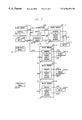
- FIG. 1 shows a logical representation of an exemplary embodiment of the invention in which communication is achieved digitally and the particular conference bridge employed at any particular time during a call is selected so as to minimize the overall cost of a call based on prescribed call cost criteria;
- FIG. 2 shows the addition of a device server to the conference call shown in FIG. 1;
- FIG. 3 shows how the conference call shown in FIG. 2 is changed after two device servers are dropped from the conference call and a device server is added to the conference call;
- FIG. 4 shows a more traditional view of a network in accordance with principles of the invention.
- processors may be provided through the use of dedicated hardware as well as hardware capable of executing software in association with appropriate software.
- the functions may be provided by a single dedicated processor, by a single shared processor, or by a plurality of individual processors, some of which may be shared.
- explicit use of the term “processor” or “controller” should not be construed to refer exclusively to hardware capable of executing software, and may implicitly include, without limitation, digital signal processor (DSP) hardware, read-only memory (ROM) for storing software, random access memory (RAM), and non-volatile storage. Other hardware, conventional and/or custom, may also be included.
- DSP digital signal processor
- ROM read-only memory
- RAM random access memory
- non-volatile storage non-volatile storage
- any switches shown in the FIGS. are conceptual only. Their function may be carried out through the operation of program logic, through dedicated logic, through the interaction of program control and dedicated logic, or even manually, the particular technique being selectable by the implementor as more specifically understood from the context.
- any element expressed as a means for performing a specified function is intended to encompass any way of performing that function including, for example, a) a combination of circuit elements which performs that function or b) software in any form, including, therefore, firmware, microcode or the like, combined with appropriate circuitry for executing that software to perform the function.
- the invention as defined by such claims resides in the fact that the functionalities provided by the various recited means are combined and brought together in the manner which the claims call for. Applicant thus regards any means which can provide those functionalities as equivalent as those shown herein.
- a conference bridge is selected for a conference call so as to reduce the overall cost of the conference call, and the conference bride selected may be changed dynamically, e.g., as parties are added or dropped from the conference call, so as to continuously maintain the low cost of the conference call.
- FIG. 1 shows a logical representation of an exemplary embodiment of the invention in which communication is achieved digitally and the particular conference bridge employed at any particular time during a call is selected so as to minimize the overall cost of a call based on prescribed call cost criteria.
- FIG. 1 shows a) device servers 101 , including device servers 101 - 1 through 101 -N; b) devices 103 , including devices 103 - 1 through 103 -N; c) call coordinator 105 ; conference bridges 107 , including conference bridges 107 - 1 through 107 -N; d) links 113 and 115 ; and e) data network links 119 which together form a data network.
- Device servers 101 are protocol translators which translate the protocol of a device being served by the device server to a common call control protocol.
- Each of device servers 101 include at least a control unit 109 and they each may also include a packet circuit gateway 111 to handle the media portion, e.g., voice and/or video, of the call.
- Control unit 109 is typically implemented by a processor running software, the processor including, or being coupled to, a packet communication interface.
- Each packet circuit gateway 111 may include a processor, which may be shared with control unit 109 , and may also include media processing capabilities, such as digital to analog and analog to digital converters for media and capabilities to packetize media or reconstruct media from packetized format.
- server is used in the conventional manner of the “client-server” architecture, where the server serves request from the clients and does not take action unless it is in response to a client request.
- Each device server 101 maintains protocol state information for the protocol that it uses to communicate with call coordinator 105 .
- Each device server 101 exposes itself as a hierarchical namespace so that any client that wants to make use services provided by any particular one of device servers 101 accesses that particular one of device servers 101 as if it is accessing a distributed file system.
- Typical device servers represent physical/logical telephone devices, which include a) end-point device servers and b) gateway device servers.
- a primary function of device servers 101 is to act as an interface between the data network made up of links 119 that connects device servers 101 and call coordinator 105 and some other external network or device, e.g., a legacy network or a legacy piece of equipment.
- each device server 101 may be a valid entity in a legacy network that can employ the appropriate protocol of that legacy network.
- device servers 101 shield call coordinator 105 from specific signaling protocols of the legacy network or legacy equipment to which they respectively connect. This is achieved by maintaining protocol specific state in device servers 101 .
- Devices 103 are any communication tool, such as a conventional plain old telephone service (POTS) telephone, an Internet protocol (IP) telephone, or telecommunications switches.
- POTS plain old telephone service
- IP Internet protocol
- the individual ones of devices 103 e.g., device 103 - 1 and device 103 -N, need not be the same.
- devices 103 are, collectively, all the devices connected to the communications system of FIG. 1 .
- Each particular one of devices 103 is interfaced to one of device servers 101 . Such a connection is necessary for control purposes, as each device server 101 includes one of control units 109 . However, each device 103 need not be interfaced to a one of device servers 101 that has a packet circuit gateway for media purposes, such as if the device being interfaced already is compatible with the protocol employed by the data network made up of data network links 119 .
- One such device is device 103 - 1 , which can transmit directly over the network, such as an IP telephone, and so it is coupled to device server 101 - 1 , which does not include a packet circuit gateway.
- a call coordinator such as call coordinator 105 , accomplishes communications among various device servers.
- Call coordinator may be implemented as a software module that is executed by a computer connected to the network to which the device servers are attached.
- the computer executing call coordinator 105 may be separate from the computer, or computers, of device servers 101 , or it may share processing power with one or more of the computers of device servers 101 , or other computers attached to the network.
- the functionality of call coordinator 105 may be distributed over several computers, which may be separate from, or shared with, the computers of device servers 101 , in any combination.
- a single network may have more than one call coordinator attached to it, with each call coordinator handling zero, one, or more calls.
- call coordinator 105 functions in the role of the “client” of the conventional “client-server” architecture, e.g., it initiates requests for services to the various ones of device servers 101 . Typically, such requests are in response to a so-called “event” that is detected by call coordinator 105 . Since the call coordinator is the client, it is able to request service from various ones of device servers 101 as is appropriate for the service being provided on a particular call and consistent with stored rules or registrations.
- Each of device servers 101 are unaware of communication state, which is the interaction among multiple device servers. Instead, communication state is maintained by call coordinator 105 , which exposes the communication state as a hierarchical namespace. As a client of device servers 101 , call coordinator 105 manipulates device servers 101 to accomplish communications. Call coordinator 105 furthermore captures and exports such an interaction, known as a “call session”, as a hierarchical namespace.
- Call coordinator 105 treats the processing of a call as a sequence of steps each of which can be implemented by a small piece of computer executable code called a “feature applet”.
- Feature applets perform a specific step in call processing and as part of the step it typically manipulates the call tree of the namespace exposed by call coordinator 105 . That is, apart from loading the feature applets, call coordinator 105 and the feature applets communicate entirely through a call tree.
- Feature applets can be dynamically loaded and executed by call coordinator 105 .
- the feature applet code can be located somewhere else in the network and can be loaded on the fly from the network, or the feature applet itself can even be executed somewhere else in the network. Since the session state is manipulated using the call tree which is exposed by the call coordinator as a hierarchical namespace, the location where the feature applet executes, as part of processing the current call/session is irrelevant.
- Call coordinator 105 supports an explicit user model. That is, users of the system are authenticated by the call coordinator and are bound to specific devices. Users of the system may also dictate what feature applets are run by call coordinator 105 while processing a call on their behalf. To accomplish this, feature applets may be logically grouped for every user of the system.
- call coordinator 105 provides a facility for incrementally evolving the system for each user.
- a call consists of one or more users with each user controlling one or more device servers 101 .
- Call coordinator 105 controls the adding and dropping of users as well as actual ones of device serves 101 to the conference, in addition to specifying which of conference bridges 107 should be used for any particular time for any call.
- call coordinator 105 may arrange for direct connection between ones of device servers 101 when there are only two device servers on a call rather than using one of conference bridges 107 .
- call coordinator 105 may specify that more than one conference bridge 107 is to be employed, the conference bridges being linked, if doing so results in an overall lower cost. Such a situation may result, for example, if groups of devices 101 on a single call are clustered geographically, e.g., three in the United States and four in Europe.
- Conference bridges 107 perform conferencing functions, including media mixing. They may also perform media functionalities such as mute, hold, add sound effects at the behest of call coordinator 105 . Conference bridges may also include, or make use of, transcoding capabilities, i.e., the ability to transform one media format to another. For example, a conference bridge may transform media between Lucent SX7300P coder format and G 711 standard media format. Furthermore, some conference bridges may be capable of handling data of different types and formats, e.g., voice and video or voice in various formats such as G 711 mu-law at 64 Kbps and G.729 encoded voice at 6 Kpbs, while some conference bridges can handle data of only a single type or a single format.
- transcoding capabilities i.e., the ability to transform one media format to another. For example, a conference bridge may transform media between Lucent SX7300P coder format and G 711 standard media format.
- some conference bridges may be capable of handling data of different types and formats, e
- Data network links 119 form a data network, for example, an Internet-like network or a so-called intranet.
- link 121 may be a data network link similar to data network links 119 or it may proprietary type of link unique to the use of device 111 .
- Data network links 119 may be links such as logical links, e.g., where real time protocol/universal datagram protocol (RTP/UDP) is used, or virtual circuit links, e.g., where asynchronous transfer mode (ATM) is employed.
- RTP/UDP real time protocol/universal datagram protocol
- ATM asynchronous transfer mode
- Links 113 are logical links which represent the transmission of control and media separately. This separation is purely for pedagogical purposes. In practice, both control and media may be sent over the same link and handled appropriately by devices 103 and their respective associated one of device servers 101 .
- a conference call is defined as any call on which there are three or more device servers 101 .
- the conference call may start out known to be a conference call or it may start out as requiring less than three device servers 101 and at least one of device server 101 is added later.
- call coordinator 105 determines that a call requires a conference bridge, e.g., the call involves more than two of device servers 101 , it arranges for one of conference bridges 107 to be used by the call.
- call coordinator 105 selects the particular one of conference bridges 107 to be employed as a function of a specified criteria.
- the criteria may include cost and/or capabilities to achieve the desired conference call.
- cost is determined by the location of the media sources for the ones of device servers 101 that are participating in the conference call, and selects one of conference bridges 107 which would minimize the cost.
- call coordinator 105 selects a particular one of conference bridges 107 for the call, it identifies the selected one of conference bridges 107 to each of device servers 101 on the call, e.g., by specifying the Internet protocol (IP) address and port.
- Call coordinator 105 also identifies each of the ones of device servers 101 to the selected one of conference bridges 107 .
- the media part of each of the ones of device servers 101 that are on the conference call then begins transmitting media in the form of packets, e.g., RTP/UDP packets, to the selected one of conference bridges 107 .
- FIG. 1 shows a conference call between three devices, devices 103 - 3 , 103 - 4 , and 103 -N. These devices are located in a geographic area that, from the point of view of the data network made up of data links 119 .
- device servers 101 - 3 , 101 - 4 , and 101 -N are shown separately in FIG. 1, because FIG. 1 is a logical representation, device servers 101 - 3 , 101 - 4 , and 101 -N may actually be implemented by a single device server, e.g., if devices 103 - 3 , 103 - 4 , and 103 -N were all connected to the same local exchange telephone switch, such as Number 5 Electronic Switching System (5ESS) available from Lucent Technologies.
- 5ESS Number 5 Electronic Switching System
- call coordinator 105 evaluates the conference call as it will be with the additional conferee and selects a conference bridge for the call.
- this conference bridge may be selected from one of the currently available conference bridges or the conference bridge that is currently being used by the conference to which the conferee is being added.
- the conference bridge may be selected from all the conference bridges and, if necessary, a conference call which may already be using the selected bridge can itself be reassigned to another conference bridge selected for it. This would typically only be done provided that the final configuration of both conference calls results in the lowest overall cost to the entire system.
- the call coordinator instruct each existing device server to start using the newly selected conference bridge, provided that it is different from the conference bridge already being used by the conference call. This may be achieved by identifying the new conference bridge to each device server on the call, e.g., by specifying the Internet protocol (IP) address and port.
- IP Internet protocol
- the call coordinator also identifies each of the device servers to the newly selected conference bridge.
- the media part of the device server then begins transmitting media in the form of packets, e.g., RTP/UDP packets, to the newly selected conference bridge. If the device server does not include packet circuit gateway for providing media, the device server instructs the device being served by the device server to provide the media directly to the newly selected conference bridge.
- FIG. 2 shows the addition of device server 101 - 1 to the conference call shown in FIG. 1 .
- the addition of device server 101 - 1 adds to the conference call devices 103 - 1 .
- the location used to determine which of conference bridges 107 to use is based on the source of the media in packet form that can go over links 119 . Because device 103 - 1 directly provides media that can go over links 119 , the location of device 103 - 1 is used. In the example of FIGS. 1 and 2 device 103 - 1 is located somewhat remotely from device servers 101 - 3 , 101 - 4 , and 101 -N. Therefore, call coordinator 105 , when adding device 103 determines that the best conference bridge to server the conference call with device 103 - 1 added on is conference bride 107 - 2 .
- call coordinator 105 Once call coordinator 105 has selected conference bridge 107 - 2 , it identifies conference bridge 107 - 2 to device servers 101 - 3 , 101 - 4 , and 101 -N, as well as device 103 - 1 .
- Device servers 101 - 3 , 101 - 4 , and 101 -N, as well as device 103 - 1 are also identified to conference bridge 107 - 2 . Thereafter, device servers 101 - 3 , 101 - 4 , and 101 -N as well as device 103 - 1 transmit media to conference bridge 107 - 2 , and receive media therefrom.
- the call coordinator evaluates the conference call as it will be with the one less conferee and selects a conference bridge for the call.
- this conference bridge may be selected from one of the currently available conference bridge or the bridge that is currently being used by the conference to which the conferee is being added.
- the conference bridge may be selected from all the conference bridges and, if necessary, a conference call which may already be using the selected bridge can itself be reassigned to another conference bridge selected for it. This would typically only be done provided that the final configuration of both conference calls results in the lowest overall cost to the entire system.
- the call coordinator instruct each existing device server to start using the newly selected conference bridge, provided that it is different from the conference bridge already being used by the conference call. This may be achieved by identifying the new conference bridge to each device server on the call, e.g., by specifying the Internet protocol (IP) address and port.
- IP Internet protocol
- the call coordinator also identifies each of the device servers to the newly selected conference bridge.
- the media part of the device server then begins transmitting media in the form of packets, e.g., RTP/UDP packets, to the newly selected conference bridge. If the device server does not include packet circuit gateway for providing media, the device server instructs the device being served by the device server to provide the media directly to the newly selected conference bridge.
- call coordinator may decide to dispense with the use of a conference bridge and to instead instruct the remaining device servers to communicate media directly with each other, e.g., by providing to each the IP and port of the other.
- FIG. 3 shows how the conference call shown in FIG. 2 is changed after device servers 101 - 4 and 101 -N are dropped from the conference call and device server 101 - 2 is added.
- the dropping of device servers 101 - 4 and 101 -N result in the dropping from the conference call of devices 103 - 4 and 103 -N.
- the addition of device server 101 - 2 adds to the conference call devices 103 - 2 .
- the resulting conference includes device servers 101 - 1 , 101 - 2 , and 101 - 3 . Because of the proximity of device servers 101 - 2 , and 101 - 3 and device 103 - 1 to each other and to conference bridge 107 - 1 , conference bridge 107 - 1 is selected as the conference bridge for the conference call by call coordinator 105 .
- call coordinator 105 Once call coordinator 105 has selected conference bridge 107 - 1 , it identifies conference bridge 107 - 1 to device servers 101 - 2 and 101 - 3 , as well as device 103 - 1 .
- Device servers 101 - 2 and 101 - 3 , as well as device 103 - 1 are also identified to conference bridge 107 - 1 . Thereafter, device servers 101 - 2 and 101 - 3 , as well as device 103 - 1 transmit media to conference bridge 107 - 1 , and receive media therefrom.
- call coordinator 105 drops device servers 101 - 4 and 101 -N from the call, and instructs them to no longer send media to conference bridge 107 - 2
- FIG. 4 shows a more traditional view of a network in accordance with principles of the invention. Shown in FIG. 4 are device servers 401 , devices 403 , data network 439 , and conference bridges 407 .
- Device servers 401 correspond to device servers 101 of FIG. 1 . However, in FIG. 4, some more explicit implementation details of a particular embodiment of device servers 401 are shown. Specifically, device servers 401 are shown to include control device server 409 , control unit 409 and they each may also include a packet circuit gateway 411 to handle the media portion, each being coupled to a No. 5ESS.
- Devices 403 are units such as telephones.
- Data network 439 is made up of data links 419 which correspond to data links 119 of FIG. 1 .
- conference bridges 407 corresponds to conference bridges 107 of FIG. 1 .
Abstract
Description
Claims (20)
Priority Applications (6)
| Application Number | Priority Date | Filing Date | Title |
|---|---|---|---|
| US09/183,994 US6584076B1 (en) | 1998-11-02 | 1998-11-02 | Telecommunications conferencing method and apparatus |
| CA002285095A CA2285095A1 (en) | 1998-11-02 | 1999-10-06 | Telecommunications conferencing method and apparatus |
| DE69921062T DE69921062T2 (en) | 1998-11-02 | 1999-10-25 | Telephone conference apparatus and method |
| EP99308424A EP0999686B1 (en) | 1998-11-02 | 1999-10-25 | Telecommunications conferencing method and apparatus |
| KR1019990048212A KR20000047586A (en) | 1998-11-02 | 1999-11-02 | Telecommunications conferencing method and apparatus |
| JP11311883A JP2000253156A (en) | 1998-11-02 | 1999-11-02 | Electrical communication conference method and device |
Applications Claiming Priority (1)
| Application Number | Priority Date | Filing Date | Title |
|---|---|---|---|
| US09/183,994 US6584076B1 (en) | 1998-11-02 | 1998-11-02 | Telecommunications conferencing method and apparatus |
Publications (1)
| Publication Number | Publication Date |
|---|---|
| US6584076B1 true US6584076B1 (en) | 2003-06-24 |
Family
ID=22675167
Family Applications (1)
| Application Number | Title | Priority Date | Filing Date |
|---|---|---|---|
| US09/183,994 Expired - Lifetime US6584076B1 (en) | 1998-11-02 | 1998-11-02 | Telecommunications conferencing method and apparatus |
Country Status (6)
| Country | Link |
|---|---|
| US (1) | US6584076B1 (en) |
| EP (1) | EP0999686B1 (en) |
| JP (1) | JP2000253156A (en) |
| KR (1) | KR20000047586A (en) |
| CA (1) | CA2285095A1 (en) |
| DE (1) | DE69921062T2 (en) |
Cited By (29)
| Publication number | Priority date | Publication date | Assignee | Title |
|---|---|---|---|---|
| US20020191766A1 (en) * | 2001-06-13 | 2002-12-19 | Siemens Ag. | System for setting up and controlling a conference circuit |
| US20040213209A1 (en) * | 2003-04-22 | 2004-10-28 | O'connor Neil | Processing of communication session request messages |
| US6831899B1 (en) * | 2000-08-18 | 2004-12-14 | At&T Corp. | Voice and video/image conferencing services over the IP network with asynchronous transmission of audio and video/images integrating loosely coupled devices in the home network |
| US20050015444A1 (en) * | 2003-07-15 | 2005-01-20 | Darwin Rambo | Audio/video conferencing system |
| US20050243977A1 (en) * | 2004-04-28 | 2005-11-03 | International Business Machines Corporation | Telecommunications voice server leveraging application web-server capabilities |
| US20060077252A1 (en) * | 2004-10-12 | 2006-04-13 | Bain John R | Method and apparatus for controlling a conference call |
| US20060098684A1 (en) * | 2002-09-30 | 2006-05-11 | Bruno Bozionek | Data communications system, computer, and data communications method for parallelly operating standard-based and proprietary resources |
| US20060146124A1 (en) * | 2004-12-17 | 2006-07-06 | Andrew Pepperell | Video conference recorder |
| US20060171336A1 (en) * | 2005-01-05 | 2006-08-03 | William Macdonald | Video multi-conference unit (MCU) |
| US20070048776A1 (en) * | 2005-08-24 | 2007-03-01 | The Scripps Research Institute | Translation enhancer-element dependent vector systems |
| US20070133413A1 (en) * | 2005-12-09 | 2007-06-14 | Andrew Pepperell | Flow control in a video conference |
| US20070276908A1 (en) * | 2006-05-23 | 2007-11-29 | Cisco Technology, Inc. | Method and apparatus for inviting non-rich media endpoints to join a conference sidebar session |
| US20080059581A1 (en) * | 2006-09-05 | 2008-03-06 | Andrew Pepperell | Viewing data as part of a video conference |
| US20080063173A1 (en) * | 2006-08-09 | 2008-03-13 | Cisco Technology, Inc. | Conference resource allocation and dynamic reallocation |
| US20080068448A1 (en) * | 2006-09-18 | 2008-03-20 | Hansen Robert A | Method for adapting a device to participate in video conference calls |
| US20080144525A1 (en) * | 2006-12-13 | 2008-06-19 | Crockett Douglas M | Method and apparatus for allocating network resources in a group communication system |
| US20080158338A1 (en) * | 2006-11-20 | 2008-07-03 | Evans Simon J W | Hardware architecture for video conferencing |
| US7580374B1 (en) * | 2000-12-22 | 2009-08-25 | At&T Intellectual Property, I, L.P. | Systems and methods for setting future teleconference calls |
| US7764632B2 (en) * | 2006-08-24 | 2010-07-27 | Interwise Ltd. | Software bridge for multi-point multi-media teleconferencing and telecollaboration |
| US8238536B1 (en) | 2004-04-06 | 2012-08-07 | West Corporation | Call redirect via centralized bridges |
| US8458253B1 (en) * | 2008-02-28 | 2013-06-04 | West Corporation | Enterprise conferencing with dual mixing |
| US8532100B2 (en) | 2010-10-19 | 2013-09-10 | Cisco Technology, Inc. | System and method for data exchange in a heterogeneous multiprocessor system |
| US20140051383A1 (en) * | 2012-08-14 | 2014-02-20 | Gregory Joseph Doerr | System and Method of Routing Conference Call Participants |
| US8670538B1 (en) * | 2004-04-06 | 2014-03-11 | West Corporation | International conferencing via globally distributed cascading servers |
| WO2014165685A1 (en) * | 2013-04-03 | 2014-10-09 | Level 3 Communications, Llc | Real time application programming interface in a telecommunications network |
| US9112932B1 (en) | 2008-02-28 | 2015-08-18 | West Corporation | Enterprise conferencing with dual mixing |
| US9183560B2 (en) | 2010-05-28 | 2015-11-10 | Daniel H. Abelow | Reality alternate |
| US9258181B1 (en) * | 2007-12-06 | 2016-02-09 | Alorica Business Solutions, Llc | Managing agent login to multiple conference call bridges |
| US20190158546A1 (en) * | 2017-11-21 | 2019-05-23 | Incontact, Inc. | Systems and methods for dynamic latency reduction for conferencing |
Families Citing this family (12)
| Publication number | Priority date | Publication date | Assignee | Title |
|---|---|---|---|---|
| US6584076B1 (en) | 1998-11-02 | 2003-06-24 | Lucent Technologies Inc. | Telecommunications conferencing method and apparatus |
| KR100545081B1 (en) * | 2001-06-30 | 2006-01-24 | 주식회사 케이티 | Remote Private Branch Exchange System for IP Phone and Method for Group Call Service using it |
| NO318975B1 (en) * | 2003-06-20 | 2005-05-30 | Tandberg Telecom As | System and procedure for setting up fashions and conferences |
| JP3916239B2 (en) * | 2003-06-30 | 2007-05-16 | Necエンジニアリング株式会社 | Multi-party call system and multi-party call method |
| EP1501272B1 (en) * | 2003-07-23 | 2012-09-26 | France Telecom | Method of organising a conference call |
| EP1501271A1 (en) * | 2003-07-23 | 2005-01-26 | France Telecom | Method of organising a conference call |
| JP2007150851A (en) * | 2005-11-29 | 2007-06-14 | Toshiba Corp | Master device of communication system and conference connection method of communication system |
| US8699384B2 (en) * | 2006-03-15 | 2014-04-15 | American Teleconferencing Services, Ltd. | VOIP conferencing |
| EP2053869A1 (en) * | 2007-10-24 | 2009-04-29 | Alcatel Lucent | Media server selection for conference within a call control system |
| CN101170427B (en) * | 2007-11-23 | 2010-06-02 | 中兴通讯股份有限公司 | An audio conference access method |
| JP5405033B2 (en) * | 2008-03-18 | 2014-02-05 | 株式会社Nttドコモ | Call control device |
| US9167098B1 (en) * | 2014-09-29 | 2015-10-20 | Edifire LLC | Dynamic conference session re-routing in secure media-based conferencing |
Citations (9)
| Publication number | Priority date | Publication date | Assignee | Title |
|---|---|---|---|---|
| US4796293A (en) | 1987-12-18 | 1989-01-03 | Communications Network Enhancement Inc. | Enhanced dedicated teleconferencing system |
| US5828743A (en) | 1995-05-12 | 1998-10-27 | Protel, Inc. | Apparatus and method for automated audio teleconferencing having enhanced access and security features |
| US5991276A (en) * | 1996-11-19 | 1999-11-23 | Fujitsu Limited | Videoconference system |
| US5995608A (en) | 1997-03-28 | 1999-11-30 | Confertech Systems Inc. | Method and apparatus for on-demand teleconferencing |
| US6035026A (en) * | 1997-06-27 | 2000-03-07 | Samsung Electronics Co., Ltd. | Method and apparatus of call conferencing in a telephone exchange system |
| EP0999686A2 (en) | 1998-11-02 | 2000-05-10 | Lucent Technologies Inc. | Telecommunications conferencing method and apparatus |
| US6088361A (en) * | 1997-05-06 | 2000-07-11 | International Business Machines Corp. | Timed division multiplex bus connection controller |
| US6163544A (en) * | 1995-12-08 | 2000-12-19 | Telefonaktiebolaget Lm Ericsson | Configuration method for auxiliary resources |
| US6337864B1 (en) * | 1997-10-10 | 2002-01-08 | Fujitsu Limited | Information transmission apparatus, information transmission method, and medium recorded with information transmission program, in store-and-forward type of electronic conference system |
-
1998
- 1998-11-02 US US09/183,994 patent/US6584076B1/en not_active Expired - Lifetime
-
1999
- 1999-10-06 CA CA002285095A patent/CA2285095A1/en not_active Abandoned
- 1999-10-25 EP EP99308424A patent/EP0999686B1/en not_active Expired - Lifetime
- 1999-10-25 DE DE69921062T patent/DE69921062T2/en not_active Expired - Lifetime
- 1999-11-02 KR KR1019990048212A patent/KR20000047586A/en not_active Application Discontinuation
- 1999-11-02 JP JP11311883A patent/JP2000253156A/en active Pending
Patent Citations (9)
| Publication number | Priority date | Publication date | Assignee | Title |
|---|---|---|---|---|
| US4796293A (en) | 1987-12-18 | 1989-01-03 | Communications Network Enhancement Inc. | Enhanced dedicated teleconferencing system |
| US5828743A (en) | 1995-05-12 | 1998-10-27 | Protel, Inc. | Apparatus and method for automated audio teleconferencing having enhanced access and security features |
| US6163544A (en) * | 1995-12-08 | 2000-12-19 | Telefonaktiebolaget Lm Ericsson | Configuration method for auxiliary resources |
| US5991276A (en) * | 1996-11-19 | 1999-11-23 | Fujitsu Limited | Videoconference system |
| US5995608A (en) | 1997-03-28 | 1999-11-30 | Confertech Systems Inc. | Method and apparatus for on-demand teleconferencing |
| US6088361A (en) * | 1997-05-06 | 2000-07-11 | International Business Machines Corp. | Timed division multiplex bus connection controller |
| US6035026A (en) * | 1997-06-27 | 2000-03-07 | Samsung Electronics Co., Ltd. | Method and apparatus of call conferencing in a telephone exchange system |
| US6337864B1 (en) * | 1997-10-10 | 2002-01-08 | Fujitsu Limited | Information transmission apparatus, information transmission method, and medium recorded with information transmission program, in store-and-forward type of electronic conference system |
| EP0999686A2 (en) | 1998-11-02 | 2000-05-10 | Lucent Technologies Inc. | Telecommunications conferencing method and apparatus |
Cited By (58)
| Publication number | Priority date | Publication date | Assignee | Title |
|---|---|---|---|---|
| US6831899B1 (en) * | 2000-08-18 | 2004-12-14 | At&T Corp. | Voice and video/image conferencing services over the IP network with asynchronous transmission of audio and video/images integrating loosely coupled devices in the home network |
| US7580374B1 (en) * | 2000-12-22 | 2009-08-25 | At&T Intellectual Property, I, L.P. | Systems and methods for setting future teleconference calls |
| US20020191766A1 (en) * | 2001-06-13 | 2002-12-19 | Siemens Ag. | System for setting up and controlling a conference circuit |
| US7805968B2 (en) * | 2001-06-13 | 2010-10-05 | Siemens Aktiengesellschaft | System for setting up and controlling a conference circuit |
| US20060098684A1 (en) * | 2002-09-30 | 2006-05-11 | Bruno Bozionek | Data communications system, computer, and data communications method for parallelly operating standard-based and proprietary resources |
| US20040213209A1 (en) * | 2003-04-22 | 2004-10-28 | O'connor Neil | Processing of communication session request messages |
| US7313131B2 (en) * | 2003-04-22 | 2007-12-25 | Nortel Networks Limited | Processing of communication session request messages |
| US20050015444A1 (en) * | 2003-07-15 | 2005-01-20 | Darwin Rambo | Audio/video conferencing system |
| US9641804B2 (en) | 2003-07-15 | 2017-05-02 | Avago Technologies General Ip (Singapore) Pte. Ltd. | Audio/video conferencing system |
| US9250777B2 (en) | 2003-07-15 | 2016-02-02 | Broadcom Corporation | Audio/video conferencing system |
| US8670540B1 (en) | 2004-04-06 | 2014-03-11 | West Corporation | Call redirect via centralized bridges |
| US8670538B1 (en) * | 2004-04-06 | 2014-03-11 | West Corporation | International conferencing via globally distributed cascading servers |
| US9118781B1 (en) | 2004-04-06 | 2015-08-25 | West Corporation | Call redirect via centralized bridges |
| US8238536B1 (en) | 2004-04-06 | 2012-08-07 | West Corporation | Call redirect via centralized bridges |
| US9148515B1 (en) | 2004-04-06 | 2015-09-29 | West Corporation | International conferencing via globally distributed cascading servers |
| US8477922B1 (en) * | 2004-04-06 | 2013-07-02 | West Corporation | Call redirect via centralized bridges |
| US8731170B1 (en) * | 2004-04-06 | 2014-05-20 | West Corporation | Call redirect via centralized bridges |
| US7839983B2 (en) * | 2004-04-28 | 2010-11-23 | Nuance Communications, Inc. | Telecommunications voice server leveraging application web-server capabilities |
| US20050243977A1 (en) * | 2004-04-28 | 2005-11-03 | International Business Machines Corporation | Telecommunications voice server leveraging application web-server capabilities |
| US7412038B2 (en) * | 2004-04-28 | 2008-08-12 | International Business Machines Corporation | Telecommunications voice server leveraging application web-server capabilities |
| US20080267370A1 (en) * | 2004-04-28 | 2008-10-30 | International Business Machines Corporation | Telecommunications voice server leveraging application web-server capabilities |
| US20080267367A1 (en) * | 2004-04-28 | 2008-10-30 | International Business Machines Corporation | Telecommunications voice server leveraging application web-server capabilities |
| US8204181B2 (en) * | 2004-04-28 | 2012-06-19 | Nuance Communications, Inc. | Telecommunications voice server leveraging application web-server capabilities |
| US20060077252A1 (en) * | 2004-10-12 | 2006-04-13 | Bain John R | Method and apparatus for controlling a conference call |
| US7312809B2 (en) | 2004-10-12 | 2007-12-25 | Codian Ltd. | Method and apparatus for controlling a conference call |
| US20060146124A1 (en) * | 2004-12-17 | 2006-07-06 | Andrew Pepperell | Video conference recorder |
| US7532231B2 (en) | 2004-12-17 | 2009-05-12 | Codian Limited | Video conference recorder |
| US20060171336A1 (en) * | 2005-01-05 | 2006-08-03 | William Macdonald | Video multi-conference unit (MCU) |
| US20070048776A1 (en) * | 2005-08-24 | 2007-03-01 | The Scripps Research Institute | Translation enhancer-element dependent vector systems |
| US20070133413A1 (en) * | 2005-12-09 | 2007-06-14 | Andrew Pepperell | Flow control in a video conference |
| US8326927B2 (en) | 2006-05-23 | 2012-12-04 | Cisco Technology, Inc. | Method and apparatus for inviting non-rich media endpoints to join a conference sidebar session |
| US20070276908A1 (en) * | 2006-05-23 | 2007-11-29 | Cisco Technology, Inc. | Method and apparatus for inviting non-rich media endpoints to join a conference sidebar session |
| US20080063173A1 (en) * | 2006-08-09 | 2008-03-13 | Cisco Technology, Inc. | Conference resource allocation and dynamic reallocation |
| US8526336B2 (en) * | 2006-08-09 | 2013-09-03 | Cisco Technology, Inc. | Conference resource allocation and dynamic reallocation |
| US7764632B2 (en) * | 2006-08-24 | 2010-07-27 | Interwise Ltd. | Software bridge for multi-point multi-media teleconferencing and telecollaboration |
| US9065667B2 (en) | 2006-09-05 | 2015-06-23 | Codian Limited | Viewing data as part of a video conference |
| US20080059581A1 (en) * | 2006-09-05 | 2008-03-06 | Andrew Pepperell | Viewing data as part of a video conference |
| US20080068448A1 (en) * | 2006-09-18 | 2008-03-20 | Hansen Robert A | Method for adapting a device to participate in video conference calls |
| US7889226B2 (en) | 2006-11-20 | 2011-02-15 | Codian Ltd | Hardware architecture for video conferencing |
| US8169464B2 (en) | 2006-11-20 | 2012-05-01 | Codian Ltd | Hardware architecture for video conferencing |
| US20080158338A1 (en) * | 2006-11-20 | 2008-07-03 | Evans Simon J W | Hardware architecture for video conferencing |
| US20090213126A1 (en) * | 2006-11-20 | 2009-08-27 | Codian Ltd | Hardware Architecture for Video Conferencing |
| US8559610B2 (en) | 2006-12-13 | 2013-10-15 | Qualcomm Incorporated | Method and apparatus for allocating network resources in a group communication system |
| US20080144525A1 (en) * | 2006-12-13 | 2008-06-19 | Crockett Douglas M | Method and apparatus for allocating network resources in a group communication system |
| US9661141B1 (en) * | 2007-12-06 | 2017-05-23 | Alorica Business Solutions, Llc | Managing agent login to multiple conference call bridges |
| US9258181B1 (en) * | 2007-12-06 | 2016-02-09 | Alorica Business Solutions, Llc | Managing agent login to multiple conference call bridges |
| US9413791B1 (en) | 2008-02-28 | 2016-08-09 | West Corporation | Enterprise conferencing with dual mixing |
| US9112932B1 (en) | 2008-02-28 | 2015-08-18 | West Corporation | Enterprise conferencing with dual mixing |
| US8458253B1 (en) * | 2008-02-28 | 2013-06-04 | West Corporation | Enterprise conferencing with dual mixing |
| US9183560B2 (en) | 2010-05-28 | 2015-11-10 | Daniel H. Abelow | Reality alternate |
| US11222298B2 (en) | 2010-05-28 | 2022-01-11 | Daniel H. Abelow | User-controlled digital environment across devices, places, and times with continuous, variable digital boundaries |
| US8532100B2 (en) | 2010-10-19 | 2013-09-10 | Cisco Technology, Inc. | System and method for data exchange in a heterogeneous multiprocessor system |
| US8942683B2 (en) * | 2012-08-14 | 2015-01-27 | Gregory Joseph Doerr | System and method of routing conference call participants |
| US20140051383A1 (en) * | 2012-08-14 | 2014-02-20 | Gregory Joseph Doerr | System and Method of Routing Conference Call Participants |
| WO2014165685A1 (en) * | 2013-04-03 | 2014-10-09 | Level 3 Communications, Llc | Real time application programming interface in a telecommunications network |
| US10764075B2 (en) | 2013-04-03 | 2020-09-01 | Level 3 Communications, Llc | Real time application programming interface in a telecommunications network |
| US20190158546A1 (en) * | 2017-11-21 | 2019-05-23 | Incontact, Inc. | Systems and methods for dynamic latency reduction for conferencing |
| US10454978B2 (en) * | 2017-11-21 | 2019-10-22 | Incontact, Inc. | Systems and methods for dynamic latency reduction for conferencing |
Also Published As
| Publication number | Publication date |
|---|---|
| DE69921062T2 (en) | 2005-10-27 |
| EP0999686A2 (en) | 2000-05-10 |
| KR20000047586A (en) | 2000-07-25 |
| CA2285095A1 (en) | 2000-05-02 |
| JP2000253156A (en) | 2000-09-14 |
| EP0999686B1 (en) | 2004-10-13 |
| EP0999686A3 (en) | 2000-10-11 |
| DE69921062D1 (en) | 2004-11-18 |
Similar Documents
| Publication | Publication Date | Title |
|---|---|---|
| US6584076B1 (en) | Telecommunications conferencing method and apparatus | |
| US6600733B2 (en) | System for interconnecting packet-switched and circuit-switched voice communications | |
| US6320857B1 (en) | Telephone doubler arrangement | |
| US6173044B1 (en) | Multipoint simultaneous voice and data services using a media splitter gateway architecture | |
| US6584490B1 (en) | System and method for providing call-handling services on a data network telephone system | |
| US7532713B2 (en) | System and method for voice over internet protocol audio conferencing | |
| US6446127B1 (en) | System and method for providing user mobility services on a telephony network | |
| US7079495B1 (en) | System and method for enabling multicast telecommunications | |
| US7787611B1 (en) | Packet telephony bridging server | |
| US6400816B1 (en) | Network-independent communications system | |
| CA2642011C (en) | System and method for recording calls in an ip-based communications system | |
| US9398160B2 (en) | Method and communication terminal for providing VoIP | |
| JP2001203726A (en) | System, method and device for communication | |
| US9185232B2 (en) | Method and apparatus for creating and distributing cost telephony-switching functionality within an IP network | |
| US20090299735A1 (en) | Method for Transferring an Audio Stream Between a Plurality of Terminals | |
| US7474665B2 (en) | Apparatus and method for compulsively receiving multi-calls over internet protocol phones in internet protocol telephony system | |
| US20020191769A1 (en) | Connection-selection method and telecommunication endpoint device | |
| KR100598351B1 (en) | The conference aparatus applied between another networks | |
| EP0998109B1 (en) | A communication network utilizing autonomous servers to establish a communication session | |
| US20150036548A1 (en) | System and method for recording calls in an ip-based communications system | |
| Chowdhury et al. | Voice over IP |
Legal Events
| Date | Code | Title | Description |
|---|---|---|---|
| AS | Assignment |
Owner name: LUCENT TECHNOLOGIES INC., NEW JERSEY Free format text: ASSIGNMENT OF ASSIGNORS INTEREST;ASSIGNORS:ARAVAMUDAN, MURALI;IYER, PRAKASH;REEL/FRAME:009561/0015 Effective date: 19981102 |
|
| FEPP | Fee payment procedure |
Free format text: PAYOR NUMBER ASSIGNED (ORIGINAL EVENT CODE: ASPN); ENTITY STATUS OF PATENT OWNER: LARGE ENTITY |
|
| STCF | Information on status: patent grant |
Free format text: PATENTED CASE |
|
| FPAY | Fee payment |
Year of fee payment: 4 |
|
| FEPP | Fee payment procedure |
Free format text: PAYER NUMBER DE-ASSIGNED (ORIGINAL EVENT CODE: RMPN); ENTITY STATUS OF PATENT OWNER: LARGE ENTITY Free format text: PAYOR NUMBER ASSIGNED (ORIGINAL EVENT CODE: ASPN); ENTITY STATUS OF PATENT OWNER: LARGE ENTITY |
|
| FPAY | Fee payment |
Year of fee payment: 8 |
|
| AS | Assignment |
Owner name: CREDIT SUISSE AG, NEW YORK Free format text: SECURITY INTEREST;ASSIGNOR:ALCATEL-LUCENT USA INC.;REEL/FRAME:030510/0627 Effective date: 20130130 |
|
| FEPP | Fee payment procedure |
Free format text: PAYER NUMBER DE-ASSIGNED (ORIGINAL EVENT CODE: RMPN); ENTITY STATUS OF PATENT OWNER: LARGE ENTITY Free format text: PAYOR NUMBER ASSIGNED (ORIGINAL EVENT CODE: ASPN); ENTITY STATUS OF PATENT OWNER: LARGE ENTITY |
|
| AS | Assignment |
Owner name: ALCATEL-LUCENT USA INC., NEW JERSEY Free format text: MERGER;ASSIGNOR:LUCENT TECHNOLOGIES INC.;REEL/FRAME:033053/0885 Effective date: 20081101 |
|
| AS | Assignment |
Owner name: SOUND VIEW INNOVATIONS, LLC, NEW JERSEY Free format text: ASSIGNMENT OF ASSIGNORS INTEREST;ASSIGNOR:ALCATEL LUCENT;REEL/FRAME:033416/0763 Effective date: 20140630 |
|
| AS | Assignment |
Owner name: ALCATEL-LUCENT USA INC., NEW JERSEY Free format text: RELEASE BY SECURED PARTY;ASSIGNOR:CREDIT SUISSE AG;REEL/FRAME:033949/0531 Effective date: 20140819 |
|
| FPAY | Fee payment |
Year of fee payment: 12 |
|
| AS | Assignment |
Owner name: NOKIA OF AMERICA CORPORATION, DELAWARE Free format text: CHANGE OF NAME;ASSIGNOR:ALCATEL-LUCENT USA INC.;REEL/FRAME:050476/0085 Effective date: 20180103 |
|
| AS | Assignment |
Owner name: ALCATEL LUCENT, FRANCE Free format text: NUNC PRO TUNC ASSIGNMENT;ASSIGNOR:NOKIA OF AMERICA CORPORATION;REEL/FRAME:050668/0829 Effective date: 20190927 |