US6586941B2 - Battery tester with databus - Google Patents
Battery tester with databus Download PDFInfo
- Publication number
- US6586941B2 US6586941B2 US09/816,768 US81676801A US6586941B2 US 6586941 B2 US6586941 B2 US 6586941B2 US 81676801 A US81676801 A US 81676801A US 6586941 B2 US6586941 B2 US 6586941B2
- Authority
- US
- United States
- Prior art keywords
- battery
- databus
- battery tester
- tester
- electronic
- Prior art date
- Legal status (The legal status is an assumption and is not a legal conclusion. Google has not performed a legal analysis and makes no representation as to the accuracy of the status listed.)
- Expired - Lifetime
Links
Images


Classifications
-
- G—PHYSICS
- G01—MEASURING; TESTING
- G01R—MEASURING ELECTRIC VARIABLES; MEASURING MAGNETIC VARIABLES
- G01R31/00—Arrangements for testing electric properties; Arrangements for locating electric faults; Arrangements for electrical testing characterised by what is being tested not provided for elsewhere
- G01R31/36—Arrangements for testing, measuring or monitoring the electrical condition of accumulators or electric batteries, e.g. capacity or state of charge [SoC]
Definitions
- the present invention relates to battery testers of the type used to test storage batteries. More specifically, the present invention relates to a modular battery tester capable of interfacing with other types of test equipment.
- Various types of battery testers are known in the art.
- One type of battery tester is based upon the measurement of a dynamic parameter, such as dynamic conductance. Examples of various battery testers and monitors are forth in U.S. Pat. No. 3,873,911, issued Mar. 25, 1975, to Champlin, entitled ELECTRONIC BATTERY TESTING DEVICE; U.S. Pat. No. 3,909,708, issued Sep. 30, 1975, to Champlin, entitled ELECTRONIC BATTERY TESTING DEVICE; U.S. Pat. No. 4,816,768, issued Mar. 28, 1989, to Champlin, entitled ELECTRONIC BATTERY TESTING DEVICE; U.S. Pat. No. 4,825,170, issued Apr.
- An electronic battery tester includes battery test circuitry configured to couple to a battery, a memory configured to log data from the battery test circuitry, and a databus configured to exchange logged data with external circuitry.
- the battery test circuitry includes memory for storing raw data.
- the databus is capable of coupling to an external device such as a hand-held device.
- the logged data can be transferred over the databus for subsequent processing in the external device.
- Example databuses include both hard wired buses as well as transmission using infrared, radio waves, etc.
- an external microprocessor based system is provided to couple to a databus and receive logged data from battery test circuitry.
- FIG. 1 is a simplified block diagram showing battery test circuitry coupled to external circuitry through a databus.
- FIG. 3 is a simplified block diagram showing battery test circuitry.
- FIG. 4 is a simplified block diagram of external circuitry configured to couple to the battery test circuitry of FIG. 3 .
- battery testers have been stand-alone units.
- the present invention provides a battery tester 10 such as that illustrated in FIG. 1 which includes a databus 12 for coupling to external circuitry 14 .
- Battery tester 10 is configured to couple to storage battery 16 through electrical connectors 18 to perform a battery test on battery 16 .
- Connectors 18 can be, for example, Kelvin type connectors.
- test circuitry 10 will obtain a dynamic parameter of the battery using an AC forcing function. Examples include dynamic conductance, resistance, admittance, impedance, their combinations, or others.
- any type of battery test can be performed including battery testing which involves application of large loads, or application of large currents or voltages such as through a charger, simple voltage measurements, etc.
- the battery tester 10 is permanently mounted in a automotive vehicle such as the type of vehicle that uses a internal combustion engine or an electric engine.
- Databus 12 is used to exchange information with external circuitry 14 .
- Such information includes, for example, raw data measurements and conclusions of battery tester 10 , and inputs, such as user inputs and other sensor inputs into battery tester 10 .
- external circuitry 14 can control battery tester 10 through databus 12 and provide information such as a battery rating to battery tester 10 for use in performing a battery test.
- Databus 12 can be a proprietary databus or can be in accordance with known standards such as RS232, CAN, ISA, PCI, PCMCIA, etc.
- Battery tester 10 can be configured to communicate with portable devices such as portable notebook computers, PDAs (Personal Data Assistants) such as a Palm PilotTM, etc.
- the databus 12 can also be configured to interface with other types of equipment which are used in the automotive industry such as “scan” tools which are used to interface with the on-board computer in a vehicle. Such scan tools are known in the art and are used to perform diagnostics and retrieve information from the on-board computer. In such an embodiment, databus 12 can be in accordance with the databus used in OBD (on-board diagnostic) systems.
- OBD on-board diagnostic
- the battery tester 10 of FIG. 1 can be a modular component of a scan tool formed by external circuitry 14 .
- the battery tester 10 is an integral component of a scan tool 20 .
- FIG. 2 also illustrates a second databus 22 which is used to couple to an on-board computer of a vehicle.
- an operator is able to perform a battery test using the same scan tool used for diagnosing other conditions of the vehicle.
- the scan tool can selectively instruct an operator to perform a battery test or control operation of the battery test based upon data retrieved from the on-board vehicle computer system through bus 22 .
- This can be part of an overall diagnostic system used to provide more accurate diagnostics of the vehicle.
- the battery test circuitry requires information through bus 22 or monitors the flow of information on a databus of the vehicle.
- the test circuit can obtain information about battery type, battery rating, and charge history. Additionally, if the vehicle contains an internal battery tester, information regarding battery tests or battery measurements can be obtained or monitored through bus 22 . In such an embodiment, test circuit 10 does not need to perform a battery test itself, or couple to the battery.
- FIG. 3 is a more detailed block diagram of battery test circuitry 10 which includes a forcing function 40 and an amplifier 42 coupled to connectors 18 .
- the forcing function 40 can be any type of signal which has a time varying component including a transient signal.
- the forcing function can be through application of a load or by applying an active signal to battery 16 .
- a response signal is sensed by amplifier 42 and provided to analog to digital converter 44 which couples to microprocessor 46 .
- Microprocessor 46 operates in accordance with instructions stored in memory 48 . In accordance with the invention, microprocessor 46 can store data into memory 48 .
- I/O Input/output
- I/O 102 can be in accordance with the desired standard or protocol as described above.
- Data collected by battery test circuitry 10 can be stored in memory 48 and transmitted over bus 12 when pulled by external circuitry 14 .
- input/output 52 comprises an RF (Radio Frequency) or IR (Infrared) input/output circuit and bus 12 comprises electromagnetic radiation.
- the logged data can comprise individual measurement points such as voltage and/or current measurements, either static or dynamic. Additionally, the logged data can comprise time and data information, operating conditions such as temperature, charge, etc. In addition to logging raw data, calculated data such as calculated conductance or battery condition, battery state of health, battery state of charge, etc. can be logged.
- FIG. 3 is simply one simplified embodiment and other embodiments are in accordance with the invention.
- Databus 12 may be capable of coupling directly to memory 48 for retrieval of stored data.
- microprocessor 46 is configured to measure a dynamic parameter based upon the forcing function 40 .
- This dynamic parameter can be correlated with battery condition as set forth in the above-mentioned Champlin and Midtronics, Inc. patents.
- FIG. 3 also illustrates an optional input/output block 50 which can be any other type of input and/or output coupled to microprocessor 46 .
- Databus 12 can also be used to provide data or instructions to microprocessor 46 . This can instruct the microprocessor 46 to perform a certain test, transmit specified data, update programming instructions, constant test parameters, etc. stored in memory 48 . Although a microprocessor 46 is shown, other types of computational or other circuitry can be used to collect and place data into memory 48 .
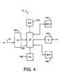
- FIG. 4 is a more detailed block diagram of external circuitry 14 .
- External circuitry 14 includes input/output (I/O) circuitry 150 for coupling to databus 12 . Again, if databus 12 is through a nonphysical connections such as infrared or radio frequency, I/O circuitry 150 should operate accordingly.
- a microprocessor 152 couples to memory 154 and operates at a rate determined by a system clock 156 . Microprocessor 152 can provide an output through display 158 and receive input from an operator through input 160 .
- circuitry 14 is operably coupled to battery test circuitry through databus 12 and is configured to send and receive information through databus 12 .
- microprocessor 152 can operate automatically, to retrieve data from memory 48 in battery test circuitry 10 .
- the microprocessor 152 can process the data to calculate battery condition and follow trends in the measured values retrieved from memory 48 . This information can be used to diagnose the condition of the battery 16 as well as use a charge and discharge history experienced by battery 16 . Further, the information can be used to validate warranty claims in which a battery is returned to a manufacturer under a claim that it is defective.
- External circuitry 14 can include additional input, output or input/output circuits 162 for communication using other techniques.
- data can be sent to a printer or other computer system. Any type of data link can be used including modems, Ethernet or networking connections, etc.
- the external circuitry 14 comprises a personal data assistant (PDA) such as a Palm PilotTM.
- PDA personal data assistant
- I/O 100 in battery test circuitry 10 can comprise a cradle which is adapted to receive the PDA.
- the PDA can simply be “dropped” into the cradle in order to exchange data with test circuitry 10 .
- many PDAs include an infrared or RF link which can be used to exchange data with battery test circuitry 10 .
- battery test circuitry 10 can include circuitry configured to charge battery 16 .
- memory 48 can be used to log information regarding any charge which is applied to battery 16 .
- battery tester 10 any type of battery test or battery test circuitry can be used by battery tester 10 .
- the databus 12 can be in accordance with any databus technique and should not be limited to the examples set forth herein.
- battery tester 10 can be powered through power received through battery 16 or can be powered through power received through databus 12 or from a scan tool.
Abstract
An electronic battery tester includes battery test circuitry configured to couple to a battery. A memory is configured to log data from the battery test circuitry and a databus configured to exchange logged data with external circuitry.
Description
The present application is based on and claims the benefit of U.S. provisional patent application Serial No. 60/192,222, filed Mar. 27, 2000, the content of which is hereby incorporated by reference in its entirety.
The present invention relates to battery testers of the type used to test storage batteries. More specifically, the present invention relates to a modular battery tester capable of interfacing with other types of test equipment.
Various types of battery testers are known in the art. One type of battery tester is based upon the measurement of a dynamic parameter, such as dynamic conductance. Examples of various battery testers and monitors are forth in U.S. Pat. No. 3,873,911, issued Mar. 25, 1975, to Champlin, entitled ELECTRONIC BATTERY TESTING DEVICE; U.S. Pat. No. 3,909,708, issued Sep. 30, 1975, to Champlin, entitled ELECTRONIC BATTERY TESTING DEVICE; U.S. Pat. No. 4,816,768, issued Mar. 28, 1989, to Champlin, entitled ELECTRONIC BATTERY TESTING DEVICE; U.S. Pat. No. 4,825,170, issued Apr. 25, 1989, to Champlin, entitled ELECTRONIC BATTERY TESTING DEVICE WITH AUTOMATIC VOLTAGE SCALING; U.S. Pat. No. 4,881,038, issued Nov. 14, 1989, to Champlin, entitled ELECTRONIC BATTERY TESTING DEVICE WITH AUTOMATIC VOLTAGE SCALING TO DETERMINE DYNAMIC CONDUCTANCE; U.S. Pat. No. 4,912,416, issued Mar. 27, 1990, to Champlin, entitled ELECTRONIC BATTERY TESTING DEVICE WITH STATE-OF-CHARGE COMPENSATION; U.S. Pat. No. 5,140,269, issued Aug. 18, 1992, to Champlin, entitled ELECTRONIC TESTER FOR ASSESSING BATTERY/CELL CAPACITY; U.S. Pat. No. 5,343,380, issued Aug. 30, 1994, entitled METHOD AND APPARATUS FOR SUPPRESSING TIME VARYING SIGNALS IN BATTERIES UNDERGOING CHARGING OR DISCHARGING; U.S. Pat. No. 5,572,136, issued Nov. 5, 1996, entitled ELECTRONIC BATTERY TESTER WITH AUTOMATIC COMPENSATION FOR LOW STATE-OF-CHARGE; U.S. Pat. No. 5,574,355, issued Nov. 12, 1996, entitled METHOD AND APPARATUS FOR DETECTION AND CONTROL OF THERMAL RUNAWAY IN A BATTERY UNDER CHARGE; U.S. Pat. No. 5,585,728, issued Dec. 17, 1996, entitled ELECTRONIC BATTERY TESTER WITH AUTOMATIC COMPENSATION FOR LOW STATE-OF-CHARGE; U.S. Pat. No. 5,592,093, issued Jan. 7, 1997, entitled ELECTRONIC BATTERY TESTING DEVICE LOOSE TERMINAL CONNECTION DETECTION VIA A COMPARISON CIRCUIT; U.S. Pat. No. 5,598,098, issued Jan. 28, 1997, entitled ELECTRONIC BATTERY TESTER WITH VERY HIGH NOISE IMMUNITY; U.S. Pat. No. 5,757,192, issued May 26, 1998, entitled METHOD AND APPARATUS FOR DETECTING A BAD CELL IN A STORAGE BATTERY; U.S. Pat. No. 5,821,756, issued Oct. 13, 1998, entitled ELECTRONIC BATTERY TESTER WITH TAILORED COMPENSATION FOR LOW STATE-OF-CHARGE; U.S. Pat. No. 5,831,435, issued Nov. 3, 1998, entitled BATTERY TESTER FOR JIS STANDARD; U.S. Pat. No. 5,914,605, issued Jun. 22, 1999, entitled ELECTRONIC BATTERY TESTER; U.S. Pat. No. 5,945,829, issued Aug. 31, 1999, entitled MIDPOINT BATTERY MONITORING; U.S. Pat. No. 6,002,238, issued Dec. 14, 1999, entitled METHOD AND APPARATUS FOR MEASURING COMPLEX IMPEDANCE OF CELLS AND BATTERIES; U.S. Pat. No. 6,037,777, issued Mar. 14, 2000, entitled METHOD AND APPARATUS FOR DETERMINING BATTERY PROPERTIES FROM COMPLEX IMPEDANCE/ADMITTANCE; U.S. Pat. No. 6,051,976, issued Apr. 18, 2000, entitled METHOD AND APPARATUS FOR AUDITING A BATTERY TEST; U.S. Pat. No. 6,081,098, issued Jun. 27, 2000, entitled METHOD AND APPARATUS FOR CHARGING A BATTERY; U.S. Pat. No. 6,091,245, issued Jul. 18, 2000, entitled METHOD AND APPARATUS FOR AUDITING A BATTERY TEST; U.S. Pat. No. 6,104,167, issued Aug. 15, 2000, entitled METHOD AND APPARATUS FOR CHARGING A BATTERY; U.S. Pat. No. 6,137,269, issued Oct. 24, 2000, entitled METHOD AND APPARATUS FOR ELECTRONICALLY EVALUATING THE INTERNAL TEMPERATURE OF AN ELECTROCHEMICAL CELL OR BATTERY; U.S. Pat. No. 6,163,156, issued Dec. 19, 2000, entitled ELECTRICAL CONNECTION FOR ELECTRONIC BATTERY TESTER; U.S. Pat. No. 6,172,483, issued Jan. 9, 2001, entitled METHOD AND APPARATUS FOR MEASURING COMPLEX IMPEDANCE OF CELL AND BATTERIES; and U.S. Pat. No. 6,172,505, issued Jan. 9, 2001, entitled ELECTRONIC BATTERY TESTER.
In general, battery testing techniques have used a single, integrated stand-alone unit.
An electronic battery tester includes battery test circuitry configured to couple to a battery, a memory configured to log data from the battery test circuitry, and a databus configured to exchange logged data with external circuitry. In various embodiments, the battery test circuitry includes memory for storing raw data. The databus is capable of coupling to an external device such as a hand-held device. The logged data can be transferred over the databus for subsequent processing in the external device. Example databuses include both hard wired buses as well as transmission using infrared, radio waves, etc.
In one aspect, an external microprocessor based system is provided to couple to a databus and receive logged data from battery test circuitry.
FIG. 1 is a simplified block diagram showing battery test circuitry coupled to external circuitry through a databus.
FIG. 2
FIG. 3 is a simplified block diagram showing battery test circuitry.
FIG. 4 is a simplified block diagram of external circuitry configured to couple to the battery test circuitry of FIG. 3.
Typically, battery testers have been stand-alone units. The present invention provides a battery tester 10 such as that illustrated in FIG. 1 which includes a databus 12 for coupling to external circuitry 14. Battery tester 10 is configured to couple to storage battery 16 through electrical connectors 18 to perform a battery test on battery 16. Connectors 18 can be, for example, Kelvin type connectors. Typically, test circuitry 10 will obtain a dynamic parameter of the battery using an AC forcing function. Examples include dynamic conductance, resistance, admittance, impedance, their combinations, or others. However, any type of battery test can be performed including battery testing which involves application of large loads, or application of large currents or voltages such as through a charger, simple voltage measurements, etc. In one embodiment, the battery tester 10 is permanently mounted in a automotive vehicle such as the type of vehicle that uses a internal combustion engine or an electric engine.
The battery tester 10 of FIG. 1 can be a modular component of a scan tool formed by external circuitry 14. In another aspect of the invention as illustrated in FIG. 2, the battery tester 10 is an integral component of a scan tool 20. FIG. 2 also illustrates a second databus 22 which is used to couple to an on-board computer of a vehicle.
In embodiments which utilize a scan tool, an operator is able to perform a battery test using the same scan tool used for diagnosing other conditions of the vehicle. Further, the scan tool can selectively instruct an operator to perform a battery test or control operation of the battery test based upon data retrieved from the on-board vehicle computer system through bus 22. This can be part of an overall diagnostic system used to provide more accurate diagnostics of the vehicle. In one embodiment, the battery test circuitry requires information through bus 22 or monitors the flow of information on a databus of the vehicle. The test circuit can obtain information about battery type, battery rating, and charge history. Additionally, if the vehicle contains an internal battery tester, information regarding battery tests or battery measurements can be obtained or monitored through bus 22. In such an embodiment, test circuit 10 does not need to perform a battery test itself, or couple to the battery.
FIG. 3 is a more detailed block diagram of battery test circuitry 10 which includes a forcing function 40 and an amplifier 42 coupled to connectors 18. In the illustration of FIG. 3, connectors 18 are shown as Kelvin connections. The forcing function 40 can be any type of signal which has a time varying component including a transient signal. The forcing function can be through application of a load or by applying an active signal to battery 16. A response signal is sensed by amplifier 42 and provided to analog to digital converter 44 which couples to microprocessor 46. Microprocessor 46 operates in accordance with instructions stored in memory 48. In accordance with the invention, microprocessor 46 can store data into memory 48.
Input/output (I/O) is provided for coupling to the databus 12. I/O 102 can be in accordance with the desired standard or protocol as described above. Data collected by battery test circuitry 10 can be stored in memory 48 and transmitted over bus 12 when pulled by external circuitry 14. In one embodiment, input/output 52 comprises an RF (Radio Frequency) or IR (Infrared) input/output circuit and bus 12 comprises electromagnetic radiation. The logged data can comprise individual measurement points such as voltage and/or current measurements, either static or dynamic. Additionally, the logged data can comprise time and data information, operating conditions such as temperature, charge, etc. In addition to logging raw data, calculated data such as calculated conductance or battery condition, battery state of health, battery state of charge, etc. can be logged.
Of course, the illustration of FIG. 3 is simply one simplified embodiment and other embodiments are in accordance with the invention. Databus 12 may be capable of coupling directly to memory 48 for retrieval of stored data. Additionally, in the illustrated embodiment microprocessor 46 is configured to measure a dynamic parameter based upon the forcing function 40. This dynamic parameter can be correlated with battery condition as set forth in the above-mentioned Champlin and Midtronics, Inc. patents. However, other types of battery tests circuitry can be used in the present invention and certain aspects of the invention should not be limited to the specific embodiment illustrated herein. FIG. 3 also illustrates an optional input/output block 50 which can be any other type of input and/or output coupled to microprocessor 46. For example, this can be used to couple to external devices or to facilitate user input and/or output. Databus 12 can also be used to provide data or instructions to microprocessor 46. This can instruct the microprocessor 46 to perform a certain test, transmit specified data, update programming instructions, constant test parameters, etc. stored in memory 48. Although a microprocessor 46 is shown, other types of computational or other circuitry can be used to collect and place data into memory 48.
FIG. 4 is a more detailed block diagram of external circuitry 14. External circuitry 14 includes input/output (I/O) circuitry 150 for coupling to databus 12. Again, if databus 12 is through a nonphysical connections such as infrared or radio frequency, I/O circuitry 150 should operate accordingly. A microprocessor 152 couples to memory 154 and operates at a rate determined by a system clock 156. Microprocessor 152 can provide an output through display 158 and receive input from an operator through input 160. In operation, circuitry 14 is operably coupled to battery test circuitry through databus 12 and is configured to send and receive information through databus 12. An operator can instruct microprocessor 152 or microprocessor 152 can operate automatically, to retrieve data from memory 48 in battery test circuitry 10. The microprocessor 152 can process the data to calculate battery condition and follow trends in the measured values retrieved from memory 48. This information can be used to diagnose the condition of the battery 16 as well as use a charge and discharge history experienced by battery 16. Further, the information can be used to validate warranty claims in which a battery is returned to a manufacturer under a claim that it is defective.
In one embodiment, the external circuitry 14 comprises a personal data assistant (PDA) such as a Palm Pilot™. In such an embodiment, I/O 100 in battery test circuitry 10 can comprise a cradle which is adapted to receive the PDA. In such an embodiment, the PDA can simply be “dropped” into the cradle in order to exchange data with test circuitry 10. Similarly, many PDAs include an infrared or RF link which can be used to exchange data with battery test circuitry 10.
In some embodiments, battery test circuitry 10 can include circuitry configured to charge battery 16. In such embodiments, memory 48 can be used to log information regarding any charge which is applied to battery 16.
Although the present invention has been described with reference to preferred embodiments, workers skilled in the art will recognize that changes may be made in form and detail without departing from the spirit and scope of the invention. For example, any type of battery test or battery test circuitry can be used by battery tester 10. Further, the databus 12 can be in accordance with any databus technique and should not be limited to the examples set forth herein. In various embodiments, battery tester 10 can be powered through power received through battery 16 or can be powered through power received through databus 12 or from a scan tool.
Claims (15)
1. An electronic battery tester comprising:
battery test circuitry configured to couple to a battery;
a memory configured to log data from the battery test circuitry;
a databus configured to exchange logged data with external circuitry; and
a Kelvin connection configured to couple to the battery.
2. The electronic battery tester of claim 1 wherein the battery tester is configured to measure a dynamic parameter of the battery as a function of an applied forcing function.
3. The electronic battery of claim 1 wherein the databus is configured to carry data to a printer.
4. The electronic battery tester of claim 1 including a memory configured to store data related to dynamic voltage and dynamic current measurements.
5. The electronic battery tester of claim 1 wherein the data stored in the memory is time stamped.
6. The electronic battery tester of claim 1 wherein the databus comprises a physical connection.
7. The electronic battery tester of claim 6 wherein the databus is in accordance with the RS232 communication standard.
8. The electronic battery tester of claim 1 wherein the databus comprises a non-physical connection.
9. The electronic battery tester of claim 8 wherein the non-physical connection comprises an infrared connection.
10. The electronic battery tester of claim 8 wherein the non-physical connection comprises a radio frequency (RF) connection.
11. The electronic battery tester of claim 1 wherein the databus is configured to couple to a personal data assistance (PDA).
12. The electronic battery tester of claim 11 wherein the battery test circuitry is responsive to instructions recorded from the PDA through the databus.
13. The battery tester of claim 1 wherein the databus is in accordance with the OBD (on-board databus) standard.
14. The electronic battery tester of claim 1 wherein the databus is configured to couple to a PCMCIA card.
15. An automotive vehicle diagnostic system comprising:
a scan tool configured to retrieve diagnostic information from a vehicle;
battery test circuitry configured to perform a battery test on a vehicle;
and a Kelvin connection configured to couple to the battery.
Priority Applications (19)
| Application Number | Priority Date | Filing Date | Title |
|---|---|---|---|
| US09/816,768 US6586941B2 (en) | 2000-03-27 | 2001-03-23 | Battery tester with databus |
| US10/200,041 US7126341B2 (en) | 1997-11-03 | 2002-07-19 | Automotive vehicle electrical system diagnostic device |
| US10/280,186 US6759849B2 (en) | 2000-03-27 | 2002-10-25 | Battery tester configured to receive a removable digital module |
| US10/460,749 US6967484B2 (en) | 2000-03-27 | 2003-06-12 | Electronic battery tester with automotive scan tool communication |
| US10/867,385 US7688074B2 (en) | 1997-11-03 | 2004-06-14 | Energy management system for automotive vehicle |
| US10/883,019 US6998847B2 (en) | 2000-03-27 | 2004-07-01 | Electronic battery tester with data bus for removable module |
| US10/958,812 US7446536B2 (en) | 2000-03-27 | 2004-10-05 | Scan tool for electronic battery tester |
| US11/063,247 US7598743B2 (en) | 2000-03-27 | 2005-02-22 | Battery maintenance device having databus connection |
| US11/146,608 US7598744B2 (en) | 2000-03-27 | 2005-06-07 | Scan tool for electronic battery tester |
| US11/352,945 US7398176B2 (en) | 2000-03-27 | 2006-02-13 | Battery testers with secondary functionality |
| US11/511,872 US7705602B2 (en) | 1997-11-03 | 2006-08-29 | Automotive vehicle electrical system diagnostic device |
| US11/585,675 US7642787B2 (en) | 1997-11-03 | 2006-10-24 | Automotive vehicle electrical system diagnostic device |
| US12/168,264 US8237448B2 (en) | 2000-03-27 | 2008-07-07 | Battery testers with secondary functionality |
| US12/204,141 US8513949B2 (en) | 2000-03-27 | 2008-09-04 | Electronic battery tester or charger with databus connection |
| US12/263,539 US7728597B2 (en) | 2000-03-27 | 2008-11-03 | Electronic battery tester with databus |
| US12/765,323 US8493022B2 (en) | 1997-11-03 | 2010-04-22 | Automotive vehicle electrical system diagnostic device |
| US12/774,892 US7924015B2 (en) | 2000-03-27 | 2010-05-06 | Automotive vehicle battery test system |
| US13/036,230 US8872516B2 (en) | 2000-03-27 | 2011-02-28 | Electronic battery tester mounted in a vehicle |
| US13/567,463 US9052366B2 (en) | 2000-03-27 | 2012-08-06 | Battery testers with secondary functionality |
Applications Claiming Priority (2)
| Application Number | Priority Date | Filing Date | Title |
|---|---|---|---|
| US19222200P | 2000-03-27 | 2000-03-27 | |
| US09/816,768 US6586941B2 (en) | 2000-03-27 | 2001-03-23 | Battery tester with databus |
Related Parent Applications (2)
| Application Number | Title | Priority Date | Filing Date |
|---|---|---|---|
| US09/575,627 Continuation-In-Part US6313608B1 (en) | 1996-07-29 | 2000-05-22 | Method and apparatus for charging a battery |
| US10/883,019 Continuation-In-Part US6998847B2 (en) | 2000-03-27 | 2004-07-01 | Electronic battery tester with data bus for removable module |
Related Child Applications (5)
| Application Number | Title | Priority Date | Filing Date |
|---|---|---|---|
| US09/564,740 Continuation-In-Part US6331762B1 (en) | 1996-07-29 | 2000-05-04 | Energy management system for automotive vehicle |
| US10/046,659 Continuation-In-Part US6909287B2 (en) | 1996-07-29 | 2001-10-29 | Energy management system for automotive vehicle |
| US10/200,041 Continuation-In-Part US7126341B2 (en) | 1997-11-03 | 2002-07-19 | Automotive vehicle electrical system diagnostic device |
| US10/280,186 Continuation-In-Part US6759849B2 (en) | 2000-03-27 | 2002-10-25 | Battery tester configured to receive a removable digital module |
| US10/460,749 Continuation-In-Part US6967484B2 (en) | 2000-03-27 | 2003-06-12 | Electronic battery tester with automotive scan tool communication |
Publications (2)
| Publication Number | Publication Date |
|---|---|
| US20020003423A1 US20020003423A1 (en) | 2002-01-10 |
| US6586941B2 true US6586941B2 (en) | 2003-07-01 |
Family
ID=46204062
Family Applications (1)
| Application Number | Title | Priority Date | Filing Date |
|---|---|---|---|
| US09/816,768 Expired - Lifetime US6586941B2 (en) | 1997-11-03 | 2001-03-23 | Battery tester with databus |
Country Status (1)
| Country | Link |
|---|---|
| US (1) | US6586941B2 (en) |
Cited By (85)
| Publication number | Priority date | Publication date | Assignee | Title |
|---|---|---|---|---|
| US20040002836A1 (en) * | 2002-06-27 | 2004-01-01 | Kurt Raichle | Apparatus and method for testing and charging a power source with ethernet |
| US20040046026A1 (en) * | 2002-09-06 | 2004-03-11 | Scott Krampitz | Code reading apparatus and method |
| US20040051533A1 (en) * | 2002-09-18 | 2004-03-18 | Hamid Namaky | Battery tester with CCA lookup table |
| US20040054503A1 (en) * | 2002-09-18 | 2004-03-18 | Hamid Namaky | Combined off-board device and starter/charging/battery system tester |
| US6759849B2 (en) * | 2000-03-27 | 2004-07-06 | Kevin I. Bertness | Battery tester configured to receive a removable digital module |
| US6806716B2 (en) | 1999-04-08 | 2004-10-19 | Kevin I. Bertness | Electronic battery tester |
| US20050264296A1 (en) * | 2004-06-01 | 2005-12-01 | Midtronics, Inc. | Battery tester capable of identifying faulty battery post adapters |
| US20060001429A1 (en) * | 2004-07-02 | 2006-01-05 | Bppower Inc. | Method of monitoring motor vehicle's electric power by comparing internal resistance of battery with a predeterminated warning resistance thereof and apparatus therefor |
| US7126341B2 (en) * | 1997-11-03 | 2006-10-24 | Midtronics, Inc. | Automotive vehicle electrical system diagnostic device |
| DE112006002329T5 (en) | 2005-08-29 | 2008-07-10 | Midtronics, Inc., Willowbrook | Diagnostic device for electrical installations of motor vehicles |
| US7408358B2 (en) * | 2003-06-16 | 2008-08-05 | Midtronics, Inc. | Electronic battery tester having a user interface to configure a printer |
| US7598744B2 (en) * | 2000-03-27 | 2009-10-06 | Midtronics, Inc. | Scan tool for electronic battery tester |
| US7656162B2 (en) | 1996-07-29 | 2010-02-02 | Midtronics Inc. | Electronic battery tester with vehicle type input |
| US7688074B2 (en) | 1997-11-03 | 2010-03-30 | Midtronics, Inc. | Energy management system for automotive vehicle |
| US7705602B2 (en) | 1997-11-03 | 2010-04-27 | Midtronics, Inc. | Automotive vehicle electrical system diagnostic device |
| US7706991B2 (en) | 1996-07-29 | 2010-04-27 | Midtronics, Inc. | Alternator tester |
| US7710119B2 (en) | 2004-12-09 | 2010-05-04 | Midtronics, Inc. | Battery tester that calculates its own reference values |
| DE102009051235A1 (en) | 2008-10-30 | 2010-05-06 | Midtronics, Inc., Willowbrook | Vehicle electrical system tester for testing electrical system of vehicle has test connection that thaws current from battery along path through wire and returns current to battery, to measure electrical parameter of wire with sensor |
| US7723993B2 (en) | 2002-09-05 | 2010-05-25 | Midtronics, Inc. | Electronic battery tester configured to predict a load test result based on open circuit voltage, temperature, cranking size rating, and a dynamic parameter |
| US7728597B2 (en) | 2000-03-27 | 2010-06-01 | Midtronics, Inc. | Electronic battery tester with databus |
| US20100153039A1 (en) * | 2002-06-27 | 2010-06-17 | Kurt Raichle | Apparatus and Method for Testing a Power Source |
| US7772850B2 (en) | 2004-07-12 | 2010-08-10 | Midtronics, Inc. | Wireless battery tester with information encryption means |
| US7774151B2 (en) | 1997-11-03 | 2010-08-10 | Midtronics, Inc. | Wireless battery monitor |
| US7777612B2 (en) | 2004-04-13 | 2010-08-17 | Midtronics, Inc. | Theft prevention device for automotive vehicle service centers |
| US7791348B2 (en) | 2007-02-27 | 2010-09-07 | Midtronics, Inc. | Battery tester with promotion feature to promote use of the battery tester by providing the user with codes having redeemable value |
| US7808375B2 (en) | 2007-04-16 | 2010-10-05 | Midtronics, Inc. | Battery run down indicator |
| US7902828B2 (en) | 2006-02-17 | 2011-03-08 | Bppower, Inc. | Method and apparatus for monitoring the condition of a battery by measuring its internal resistance |
| US7928735B2 (en) | 2007-07-23 | 2011-04-19 | Yung-Sheng Huang | Battery performance monitor |
| US7977914B2 (en) | 2003-10-08 | 2011-07-12 | Midtronics, Inc. | Battery maintenance tool with probe light |
| US7999505B2 (en) | 1997-11-03 | 2011-08-16 | Midtronics, Inc. | In-vehicle battery monitor |
| US20110207103A1 (en) * | 2010-02-19 | 2011-08-25 | Gaumard Scientific Company, Inc. | Ultrasound phantom models, materials, and methods |
| WO2011159455A1 (en) | 2010-06-18 | 2011-12-22 | Midtronics, Inc. | Battery maintenance device with thermal buffer |
| US8198900B2 (en) | 1996-07-29 | 2012-06-12 | Midtronics, Inc. | Automotive battery charging system tester |
| US8203345B2 (en) | 2007-12-06 | 2012-06-19 | Midtronics, Inc. | Storage battery and battery tester |
| US8237448B2 (en) | 2000-03-27 | 2012-08-07 | Midtronics, Inc. | Battery testers with secondary functionality |
| US20120249153A1 (en) * | 2011-04-04 | 2012-10-04 | Des Gaschons Gilles Peyrot | Electrical Power Source Battery Tester |
| US8306690B2 (en) | 2007-07-17 | 2012-11-06 | Midtronics, Inc. | Battery tester for electric vehicle |
| US8344685B2 (en) | 2004-08-20 | 2013-01-01 | Midtronics, Inc. | System for automatically gathering battery information |
| US8436619B2 (en) | 2004-08-20 | 2013-05-07 | Midtronics, Inc. | Integrated tag reader and environment sensor |
| US8442877B2 (en) | 2004-08-20 | 2013-05-14 | Midtronics, Inc. | Simplification of inventory management |
| US8513949B2 (en) | 2000-03-27 | 2013-08-20 | Midtronics, Inc. | Electronic battery tester or charger with databus connection |
| US8674711B2 (en) | 2003-09-05 | 2014-03-18 | Midtronics, Inc. | Method and apparatus for measuring a parameter of a vehicle electrical system |
| US8738309B2 (en) | 2010-09-30 | 2014-05-27 | Midtronics, Inc. | Battery pack maintenance for electric vehicles |
| US8872517B2 (en) | 1996-07-29 | 2014-10-28 | Midtronics, Inc. | Electronic battery tester with battery age input |
| US8958998B2 (en) | 1997-11-03 | 2015-02-17 | Midtronics, Inc. | Electronic battery tester with network communication |
| US8957623B2 (en) | 2011-03-16 | 2015-02-17 | Johnson Controls Technology Company | Systems and methods for controlling multiple storage devices |
| US9018958B2 (en) | 2003-09-05 | 2015-04-28 | Midtronics, Inc. | Method and apparatus for measuring a parameter of a vehicle electrical system |
| US20150168499A1 (en) * | 2013-12-12 | 2015-06-18 | Midtronics, Inc. | Battery tester and battery registration tool |
| EP2897229A1 (en) | 2014-01-16 | 2015-07-22 | Midtronics, Inc. | Battery clamp with endoskeleton design |
| US9201120B2 (en) | 2010-08-12 | 2015-12-01 | Midtronics, Inc. | Electronic battery tester for testing storage battery |
| US9229062B2 (en) | 2010-05-27 | 2016-01-05 | Midtronics, Inc. | Electronic storage battery diagnostic system |
| US9244100B2 (en) | 2013-03-15 | 2016-01-26 | Midtronics, Inc. | Current clamp with jaw closure detection |
| US9255955B2 (en) | 2003-09-05 | 2016-02-09 | Midtronics, Inc. | Method and apparatus for measuring a parameter of a vehicle electrical system |
| US9274157B2 (en) | 2007-07-17 | 2016-03-01 | Midtronics, Inc. | Battery tester for electric vehicle |
| US9312575B2 (en) | 2013-05-16 | 2016-04-12 | Midtronics, Inc. | Battery testing system and method |
| WO2016123075A1 (en) | 2015-01-26 | 2016-08-04 | Midtronics, Inc. | Alternator tester |
| US9425487B2 (en) | 2010-03-03 | 2016-08-23 | Midtronics, Inc. | Monitor for front terminal batteries |
| WO2016176405A1 (en) | 2015-04-29 | 2016-11-03 | Midtronics, Inc. | Calibration and programming of in-vehicle battery sensors |
| US9496720B2 (en) | 2004-08-20 | 2016-11-15 | Midtronics, Inc. | System for automatically gathering battery information |
| US9537332B2 (en) | 2013-05-30 | 2017-01-03 | Canara, Inc. | Apparatus, system and method for charge balancing of individual batteries in a string of batteries using battery voltage and temperature, and detecting and preventing thermal runaway |
| US9588185B2 (en) | 2010-02-25 | 2017-03-07 | Keith S. Champlin | Method and apparatus for detecting cell deterioration in an electrochemical cell or battery |
| US9619612B2 (en) | 2012-10-15 | 2017-04-11 | Battery Technology Holdings, Llc | Tester for equipment, apparatus, or component with distributed processing function |
| US9851411B2 (en) | 2012-06-28 | 2017-12-26 | Keith S. Champlin | Suppressing HF cable oscillations during dynamic measurements of cells and batteries |
| US9857430B2 (en) | 2012-10-15 | 2018-01-02 | Battery Technology Holdings, Llc | Tester for equipment, apparatus or component with distributed processing function |
| US9966676B2 (en) | 2015-09-28 | 2018-05-08 | Midtronics, Inc. | Kelvin connector adapter for storage battery |
| US10046649B2 (en) | 2012-06-28 | 2018-08-14 | Midtronics, Inc. | Hybrid and electric vehicle battery pack maintenance device |
| US10120034B2 (en) | 2015-10-07 | 2018-11-06 | Canara, Inc. | Battery string monitoring system |
| US10222397B2 (en) | 2014-09-26 | 2019-03-05 | Midtronics, Inc. | Cable connector for electronic battery tester |
| WO2019147549A1 (en) | 2018-01-23 | 2019-08-01 | Midtronics, Inc. | Hybrid and electric vehicle battery maintenance device |
| WO2019147546A1 (en) | 2018-01-23 | 2019-08-01 | Midtronics, Inc. | High capacity battery balancer |
| US10429449B2 (en) | 2011-11-10 | 2019-10-01 | Midtronics, Inc. | Battery pack tester |
| US10473555B2 (en) | 2014-07-14 | 2019-11-12 | Midtronics, Inc. | Automotive maintenance system |
| US10608353B2 (en) | 2016-06-28 | 2020-03-31 | Midtronics, Inc. | Battery clamp |
| US10843574B2 (en) | 2013-12-12 | 2020-11-24 | Midtronics, Inc. | Calibration and programming of in-vehicle battery sensors |
| WO2021092109A1 (en) | 2019-11-05 | 2021-05-14 | Midtronics, Inc. | System for charging a series of connected batteries |
| US11054480B2 (en) | 2016-10-25 | 2021-07-06 | Midtronics, Inc. | Electrical load for electronic battery tester and electronic battery tester including such electrical load |
| US11325479B2 (en) | 2012-06-28 | 2022-05-10 | Midtronics, Inc. | Hybrid and electric vehicle battery maintenance device |
| US11397210B1 (en) | 2018-06-19 | 2022-07-26 | Associated Environmental Systems, Inc. | System for high density testing of batteries within an environmental test chamber |
| US11474153B2 (en) | 2019-11-12 | 2022-10-18 | Midtronics, Inc. | Battery pack maintenance system |
| US11486930B2 (en) | 2020-01-23 | 2022-11-01 | Midtronics, Inc. | Electronic battery tester with battery clamp storage holsters |
| US11513160B2 (en) | 2018-11-29 | 2022-11-29 | Midtronics, Inc. | Vehicle battery maintenance device |
| US11566972B2 (en) | 2019-07-31 | 2023-01-31 | Midtronics, Inc. | Tire tread gauge using visual indicator |
| US11650259B2 (en) | 2010-06-03 | 2023-05-16 | Midtronics, Inc. | Battery pack maintenance for electric vehicle |
| US11668779B2 (en) | 2019-11-11 | 2023-06-06 | Midtronics, Inc. | Hybrid and electric vehicle battery pack maintenance device |
| US11740294B2 (en) | 2010-06-03 | 2023-08-29 | Midtronics, Inc. | High use battery pack maintenance |
Families Citing this family (3)
| Publication number | Priority date | Publication date | Assignee | Title |
|---|---|---|---|---|
| US7059769B1 (en) * | 1997-06-27 | 2006-06-13 | Patrick Henry Potega | Apparatus for enabling multiple modes of operation among a plurality of devices |
| US9304170B2 (en) * | 2008-03-24 | 2016-04-05 | Bosch Automotive Service Solutions Inc. | Modular heavy load battery test system |
| FR2976365B1 (en) * | 2011-06-08 | 2015-04-17 | St Microelectronics Sa | METHOD AND DEVICE FOR PROVIDING RELIABLE WEAR INFORMATION OF A BATTERY |
Citations (244)
| Publication number | Priority date | Publication date | Assignee | Title |
|---|---|---|---|---|
| US2514745A (en) | 1946-12-19 | 1950-07-11 | Heyer Ind Inc | Changeable scale electrical testing instrument |
| US3356936A (en) | 1964-02-12 | 1967-12-05 | Litton Prec Products Inc | Method and means for total battery voltage testing |
| US3562634A (en) | 1968-12-16 | 1971-02-09 | Atomic Energy Commission | Method for determining the state of charge of nickel cadmium batteries by measuring the farad capacitance thereof |
| US3593099A (en) | 1969-07-24 | 1971-07-13 | Hans K Scholl | Automatic battery tester with recording means for battery performance |
| US3607673A (en) | 1968-03-18 | 1971-09-21 | Magna Corp | Method for measuring corrosion rate |
| US3676770A (en) | 1970-05-15 | 1972-07-11 | Anderson Power Products | Pulse sampling battery fuel gauging and resistance metering method and means |
| US3729989A (en) | 1970-12-10 | 1973-05-01 | D Little | Horsepower and torque measuring instrument |
| US3753094A (en) | 1969-07-01 | 1973-08-14 | Matsushita Electric Ind Co Ltd | Ohmmeter for measuring the internal resistance of a battery and directly reading the measured resistance value |
| US3808522A (en) | 1972-11-03 | 1974-04-30 | Anderson Power Products | Method of testing the capacity of a lead-acid battery |
| US3811089A (en) | 1972-07-14 | 1974-05-14 | Gen Motors Corp | Remote engine tachometer |
| US3873911A (en) | 1971-09-14 | 1975-03-25 | Keith S Champlin | Electronic battery testing device |
| US3876931A (en) | 1972-01-14 | 1975-04-08 | Fox Prod Co | Method and apparatus for determining battery performance at one temperature when battery is at another temperature |
| US3886443A (en) | 1971-05-13 | 1975-05-27 | Asahi Optical Co Ltd | Electric camera shutter with voltage checking circuit |
| US3889248A (en) | 1970-01-28 | 1975-06-10 | Ritter Esther | Faulty battery connection indicator |
| US3906329A (en) | 1972-08-30 | 1975-09-16 | Deutsche Automobilgesellsch | Method of measuring the charge condition of galvanic energy sources and apparatus for carrying out this method |
| US3909708A (en) | 1974-01-02 | 1975-09-30 | Keith S Champlin | Electronic battery testing device |
| US3936744A (en) | 1974-04-30 | 1976-02-03 | David Perlmutter | Automotive alternator and solid state regulator tester |
| US3946299A (en) | 1975-02-11 | 1976-03-23 | Gould, Inc. | Battery state of charge gauge |
| US3947757A (en) | 1975-02-24 | 1976-03-30 | Grube Donald B | Voltage regulator tester |
| US3969667A (en) | 1972-08-23 | 1976-07-13 | The United States Of America As Represented By The Secretary Of The Navy | Device for determining the state of charge in batteries |
| US3979664A (en) | 1973-03-29 | 1976-09-07 | Brunswick Corporation | Capacitor discharge ignition testing apparatus employing visual spark gap indicator |
| US3984768A (en) | 1975-06-11 | 1976-10-05 | Champion Spark Plug Company | Apparatus for high voltage resistance measurement |
| US3984762A (en) | 1975-03-07 | 1976-10-05 | The United States Of America As Represented By The Secretary Of The Army | Method for determining battery state of charge by measuring A.C. electrical phase angle change |
| US3989544A (en) | 1973-08-22 | 1976-11-02 | Santo Charles P | Quick disconnect battery |
| US4008619A (en) | 1975-11-17 | 1977-02-22 | Mks Instruments, Inc. | Vacuum monitoring |
| US4024953A (en) | 1975-10-28 | 1977-05-24 | E. I. Du Pont De Nemours And Company | Battery snap terminal |
| US4047091A (en) | 1976-07-21 | 1977-09-06 | National Semiconductor Corporation | Capacitive voltage multiplier |
| US4053824A (en) | 1975-07-30 | 1977-10-11 | Compagnie Europeenne D'accumulateurs S.A. | Method and device for checking a storage battery |
| US4070624A (en) | 1976-07-26 | 1978-01-24 | American Generator & Armature Co. | Apparatus for testing starters and alternators |
| US4086531A (en) | 1976-04-26 | 1978-04-25 | Compunetics, Incorporated | Electrical system test apparatus |
| US4112351A (en) | 1977-09-01 | 1978-09-05 | United Technologies Corporation | Dual threshold low coil signal conditioner |
| US4114083A (en) | 1977-06-15 | 1978-09-12 | The United States Of America As Represented By The Secretary Of The Navy | Battery thermal runaway monitor |
| US4126874A (en) | 1975-12-27 | 1978-11-21 | Canon Kabushiki Kaisha | Power supply circuit for camera |
| US4178546A (en) | 1978-01-06 | 1979-12-11 | Rca Corporation | Alternator test apparatus and method |
| US4193025A (en) | 1977-12-23 | 1980-03-11 | Globe-Union, Inc. | Automatic battery analyzer |
| US4207611A (en) | 1978-12-18 | 1980-06-10 | Ford Motor Company | Apparatus and method for calibrated testing of a vehicle electrical system |
| US4217645A (en) | 1979-04-25 | 1980-08-12 | Barry George H | Battery monitoring system |
| EP0022450A1 (en) | 1979-07-03 | 1981-01-21 | Robert Bosch Gmbh | Test method for DC sources like batteries, and test device therefor |
| US4297639A (en) | 1978-12-13 | 1981-10-27 | Branham Tillman W | Battery testing apparatus with overload protective means |
| US4315204A (en) | 1980-05-22 | 1982-02-09 | Motorola, Inc. | Ripple detector for automotive alternator battery charging systems |
| US4316185A (en) | 1980-07-17 | 1982-02-16 | General Electric Company | Battery monitor circuit |
| US4322685A (en) | 1980-02-29 | 1982-03-30 | Globe-Union Inc. | Automatic battery analyzer including apparatus for determining presence of single bad cell |
| US4351405A (en) | 1978-10-12 | 1982-09-28 | Hybricon Inc. | Hybrid car with electric and heat engine |
| US4361809A (en) * | 1980-11-20 | 1982-11-30 | Ford Motor Company | Battery diagnostic method and apparatus |
| US4363407A (en) | 1981-01-22 | 1982-12-14 | Polaroid Corporation | Method and system for testing and sorting batteries |
| US4369407A (en) | 1979-08-29 | 1983-01-18 | Sheller-Globe Corporation | Regulator tester |
| US4379990A (en) | 1980-05-22 | 1983-04-12 | Motorola Inc. | Fault detection and diagnostic system for automotive battery charging systems |
| US4379989A (en) | 1979-05-11 | 1983-04-12 | Robert Bosch Gmbh | System for preventing damage to a battery charger due to application of a battery with wrong polarity |
| US4390828A (en) | 1982-03-17 | 1983-06-28 | Transaction Control Industries | Battery charger circuit |
| US4392101A (en) | 1978-05-31 | 1983-07-05 | Black & Decker Inc. | Method of charging batteries and apparatus therefor |
| US4396880A (en) | 1981-06-05 | 1983-08-02 | Firing Circuits Inc. | Method and apparatus for charging a battery |
| US4408157A (en) | 1981-05-04 | 1983-10-04 | Associated Research, Inc. | Resistance measuring arrangement |
| US4412169A (en) | 1980-11-26 | 1983-10-25 | Marelli Autronica S.P.A. | Circuit for detecting and indicating faults and operating anomalies in a system for recharging electric accumulators |
| US4423378A (en) | 1981-12-04 | 1983-12-27 | Bear Automotive Service Equipment Company | Automotive battery test apparatus |
| US4423379A (en) | 1981-03-31 | 1983-12-27 | Sun Electric Corporation | Battery testing techniques |
| US4424491A (en) | 1981-05-20 | 1984-01-03 | The United States Of America As Represented By The United States Department Of Energy | Automatic voltage imbalance detector |
| US4459548A (en) | 1981-11-12 | 1984-07-10 | Snap-On Tools Corporation | Alternator testing apparatus |
| GB2088159B (en) | 1980-11-20 | 1985-01-30 | Harmer & Simmons Ltd | Battery charging apparatus |
| US4514694A (en) | 1981-07-23 | 1985-04-30 | Curtis Instruments | Quiescent battery testing method and apparatus |
| US4520353A (en) | 1982-03-26 | 1985-05-28 | Outboard Marine Corporation | State of charge indicator |
| US4633418A (en) | 1984-07-11 | 1986-12-30 | The United States Of America As Represented By The Secretary Of The Air Force | Battery control and fault detection method |
| US4659977A (en) | 1984-10-01 | 1987-04-21 | Chrysler Motors Corporation | Microcomputer controlled electronic alternator for vehicles |
| US4665370A (en) * | 1980-09-15 | 1987-05-12 | Holland John F | Method and apparatus for monitoring and indicating the condition of a battery and the related circuitry |
| US4667279A (en) | 1986-04-01 | 1987-05-19 | Hewlett-Packard Company | Transformer coupled pard bucker for DC power supplies |
| US4678998A (en) | 1985-01-25 | 1987-07-07 | Nissan Motor Company, Limited | Battery condition monitor and monitoring method |
| US4679000A (en) | 1985-06-20 | 1987-07-07 | Robert Clark | Bidirectional current time integration device |
| US4680528A (en) | 1985-03-05 | 1987-07-14 | Toko, Inc. | Battery charging device |
| US4697134A (en) | 1986-07-31 | 1987-09-29 | Commonwealth Edison Company | Apparatus and method for measuring battery condition |
| US4707795A (en) | 1983-03-14 | 1987-11-17 | Alber Engineering, Inc. | Battery testing and monitoring system |
| US4709202A (en) | 1982-06-07 | 1987-11-24 | Norand Corporation | Battery powered system |
| US4710861A (en) | 1986-06-03 | 1987-12-01 | Martin Kanner | Anti-ripple circuit |
| US4719428A (en) | 1985-06-04 | 1988-01-12 | Tif Instruments, Inc. | Storage battery condition tester utilizing low load current |
| US4743855A (en) | 1983-12-12 | 1988-05-10 | Randin Jean Paul | Method of and apparatus for measuring the state of discharge of a battery |
| US4745349A (en) | 1986-10-16 | 1988-05-17 | Allied Corporation | Apparatus and method for charging and testing batteries |
| US4816768A (en) | 1988-03-18 | 1989-03-28 | Champlin Keith S | Electronic battery testing device |
| US4820966A (en) | 1988-06-13 | 1989-04-11 | Ron Fridman | Battery monitoring system |
| US4825170A (en) | 1988-05-25 | 1989-04-25 | Champlin Keith S | Electronic battery testing device with automatic voltage scaling |
| US4849700A (en) | 1987-03-19 | 1989-07-18 | Kabushiki Kaisha Toshiba | Device for detecting residual capacity of battery |
| US4876495A (en) | 1988-06-27 | 1989-10-24 | Allied-Signal Inc. | Apparatus and method for charging and testing batteries |
| US4881038A (en) | 1988-05-25 | 1989-11-14 | Champlin Keith S | Electric battery testing device with automatic voltage scaling to determine dynamic conductance |
| US4912416A (en) | 1988-06-06 | 1990-03-27 | Champlin Keith S | Electronic battery testing device with state-of-charge compensation |
| US4913116A (en) | 1988-03-10 | 1990-04-03 | Hitachi, Ltd. | Ignition timing control apparatus for an internal combustion engine |
| US4929931A (en) | 1988-12-22 | 1990-05-29 | Honeywell Inc. | Battery monitor |
| US4931738A (en) | 1989-01-27 | 1990-06-05 | Kaufel Group, Ltd. | Battery monitoring system of cell groups and display |
| US4937528A (en) | 1988-10-14 | 1990-06-26 | Allied-Signal Inc. | Method for monitoring automotive battery status |
| US4947124A (en) | 1988-04-05 | 1990-08-07 | Habra Elektronik Gmbh | Method for charging a nickel-cadmium accumulator and simultaneously testing its condition |
| US4956597A (en) | 1987-02-04 | 1990-09-11 | American Monarch Corporation | Method and apparatus for charging batteries |
| US4968942A (en) | 1988-10-14 | 1990-11-06 | Allied-Signal Inc. | Method for monitoring aircraft battery status |
| US4968941A (en) | 1988-07-13 | 1990-11-06 | Rogers Wesley A | Apparatus for monitoring the state of charge of a battery |
| US5004979A (en) | 1987-11-03 | 1991-04-02 | Bear Automotive Service Equipment Company | Battery tach |
| US5032825A (en) | 1990-03-02 | 1991-07-16 | Motorola, Inc. | Battery capacity indicator |
| US5037778A (en) | 1989-05-12 | 1991-08-06 | Intel Corporation | Die attach using gold ribbon with gold/silicon eutectic alloy cladding |
| US5047722A (en) | 1989-04-17 | 1991-09-10 | Ssmc Inc. | Apparatus for measuring internal resistance of wet cell storage batteries having non-removable cell caps |
| US5087881A (en) | 1988-09-19 | 1992-02-11 | Peacock David J H | Ic engine cylinder output power measurement apparatus by monitoring the output of an alternator driven by the engine |
| US5095223A (en) | 1990-06-13 | 1992-03-10 | U.S. Philips Corporation | Dc/dc voltage multiplier with selective charge/discharge |
| US5126675A (en) | 1990-09-14 | 1992-06-30 | Yang Tai Her | Battery capacity monitor |
| US5140269A (en) | 1990-09-10 | 1992-08-18 | Champlin Keith S | Electronic tester for assessing battery/cell capacity |
| US5144248A (en) | 1989-05-22 | 1992-09-01 | Alexander Manufacturing Company | Method and apparatus for measuring the voltage and charge of a battery |
| US5144218A (en) | 1989-10-25 | 1992-09-01 | U.S. Philips Corporation | Device for determining the charge condition of a battery |
| US5160881A (en) | 1989-08-04 | 1992-11-03 | Robert Bosch Gmbh | Alternator for a motor vehicle having a ventilator and device for monitoring and a controlling the ventilator |
| US5170124A (en) | 1990-06-08 | 1992-12-08 | Minister Of National Defence Of Her Majesty's Canadian Government | Method and apparatus for monitoring fuel cell performance |
| US5179335A (en) | 1987-10-09 | 1993-01-12 | Norvik Inc. | Battery charger |
| US5194799A (en) | 1991-03-11 | 1993-03-16 | Battery Technologies Inc. | Booster battery assembly |
| US5204611A (en) | 1991-03-13 | 1993-04-20 | Norvik Technologies Inc. | Charging circuits for rechargeable batteries and cells |
| US5214370A (en) | 1991-09-13 | 1993-05-25 | At&T Bell Laboratories | Battery charger with thermal runaway protection |
| US5214385A (en) | 1991-05-22 | 1993-05-25 | Commonwealth Edison Company | Apparatus and method for utilizing polarization voltage to determine charge state of a battery |
| US5241275A (en) | 1991-05-31 | 1993-08-31 | At&T Bell Laboratories | Method of measuring remaining capacity of a storage cell by comparing impedance plot characteristics |
| US5254952A (en) | 1989-09-11 | 1993-10-19 | Snap-On Tools Corporation | Automatic battery and charging system tester with motor-driven carbon pile loading |
| US5266880A (en) | 1992-04-06 | 1993-11-30 | At&T Bell Laboratories | Battery monitoring circuit |
| US5281920A (en) | 1992-08-21 | 1994-01-25 | Btech, Inc. | On-line battery impedance measurement |
| US5281919A (en) | 1988-10-14 | 1994-01-25 | Alliedsignal Inc. | Automotive battery status monitor |
| US5295078A (en) | 1991-05-17 | 1994-03-15 | Best Power Technology Corporation | Method and apparatus for determination of battery run-time in uninterruptible power system |
| US5298797A (en) | 1993-03-12 | 1994-03-29 | Toko America, Inc. | Gate charge recovery circuit for gate-driven semiconductor devices |
| US5300874A (en) | 1989-09-29 | 1994-04-05 | Kabushiki Kaisha Toshiba | Intelligent power supply system for a portable computer |
| US5302902A (en) | 1991-04-26 | 1994-04-12 | The United States Of America As Represented By The Secretary Of The Army | Abnormal battery cell voltage detection circuitry |
| US5315287A (en) | 1993-01-13 | 1994-05-24 | David Sol | Energy monitoring system for recreational vehicles and marine vessels |
| US5321626A (en) | 1991-09-25 | 1994-06-14 | Spd Technologies Inc. | Battery performance monitoring and forecasting system |
| US5331268A (en) | 1993-08-02 | 1994-07-19 | Motorola, Inc. | Method and apparatus for dynamically charging a battery |
| US5336993A (en) | 1992-09-09 | 1994-08-09 | Thomas Richard E | Assembly for testing rectifiers and regulators of automotive alternators |
| US5338515A (en) | 1990-08-17 | 1994-08-16 | Catalytica, Inc. | SO2 sensor |
| US5339018A (en) | 1989-06-30 | 1994-08-16 | Analog Devices, Inc. | Integrated circuit monitor for storage battery voltage and temperature |
| US5343380A (en) | 1992-11-17 | 1994-08-30 | Champlin Keith S | Method and apparatus for suppressing time-varying signals in batteries undergoing charging or discharging |
| US5347163A (en) | 1991-02-04 | 1994-09-13 | Sharp Kabushiki Kaisha | Power supply backup device for use in portable electronic apparatus |
| US5352968A (en) | 1992-05-28 | 1994-10-04 | Apple Computer, Inc. | Battery charge state determination |
| US5365453A (en) | 1991-02-14 | 1994-11-15 | Dell Usa, L.P. | System for indicating a low battery condition |
| US5365160A (en) | 1991-09-06 | 1994-11-15 | Telxon Corporation | Apparatus and method for charging batteries |
| US5381096A (en) | 1992-04-09 | 1995-01-10 | Hirzel; Edgar A. | Method and apparatus for measuring the state-of-charge of a battery system |
| US5412323A (en) | 1990-07-02 | 1995-05-02 | Nippondenso Co., Ltd. | Battery condition detecting apparatus and charge control apparatus for automobile |
| US5426416A (en) | 1992-10-19 | 1995-06-20 | Westinghouse Electric Corporation | Automotive current sensor |
| US5432426A (en) | 1992-07-10 | 1995-07-11 | Sanyo Electric Co., Ltd. | Charging device of a secondary battery for controlling termination of charging in response to the change state of terminal voltage of the secondary battery |
| US5434495A (en) | 1989-03-31 | 1995-07-18 | Mitsubishi Denki Kabushiki Kaisha | Cognition device for battery residual capacity |
| US5442274A (en) | 1992-08-27 | 1995-08-15 | Sanyo Electric Company, Ltd. | Rechargeable battery charging method |
| US5449997A (en) | 1991-05-30 | 1995-09-12 | Black & Decker Inc. | Battery charging system having logarithmic analog-to-digital converter with automatic scaling of analog signal |
| US5449996A (en) | 1992-08-20 | 1995-09-12 | Makita Corporation | Battery charger with improved change stopping capability |
| US5451881A (en) | 1993-12-10 | 1995-09-19 | Curtis Instruments, Inc. | Method and means for adjusting battery monitor based on rate of current drawn from the battery |
| US5457377A (en) | 1992-10-01 | 1995-10-10 | Fps Power Systems Oy Ab | Method of monitoring the internal impedance of an accumulator battery in an uninterruptible power supply, and an uninterruptible power supply |
| US5469043A (en) | 1992-10-13 | 1995-11-21 | Gnb Battery Technologies Inc. | Method for optimizing the charging of lead-acid batteries and an interactive charger |
| US5485090A (en) | 1993-02-11 | 1996-01-16 | Hewlett-Packard Corporation | Method and apparatus for differentiating battery types |
| US5488300A (en) | 1994-10-21 | 1996-01-30 | Jamieson; Robert S. | Method and apparatus for monitoring the state of charge of a battery |
| US5519383A (en) | 1994-06-10 | 1996-05-21 | De La Rosa; Pablito A. | Battery and starter circuit monitoring system |
| US5528148A (en) | 1988-07-13 | 1996-06-18 | Electronic Development, Inc. | Battery monitoring and deceleration dependent fuel-saving charging system |
| US5537967A (en) | 1992-12-28 | 1996-07-23 | Nippondenso Co., Ltd. | Vibration damping control apparatus for vehicle |
| US5546317A (en) | 1993-05-06 | 1996-08-13 | Alcatel Alsthom Compagnine Generale D'electricite | System for recognizing and managing electrochemical cells |
| US5548273A (en) | 1993-06-29 | 1996-08-20 | Competition Components International Pty Ltd | Vehicle driving monitor apparatus |
| US5550485A (en) | 1993-06-04 | 1996-08-27 | Falk; Dean A. | Multifunction alternator testing device |
| US5561380A (en) | 1995-05-08 | 1996-10-01 | Chrysler Corporation | Fault detection system for electric automobile traction system having floating ground |
| US5562501A (en) | 1993-11-30 | 1996-10-08 | The Whitaker Corporation | Female electrical contact with stop for resilient contact |
| US5572136A (en) | 1992-05-01 | 1996-11-05 | Champlin; Keith S. | Electronic battery testing device |
| US5574355A (en) | 1995-03-17 | 1996-11-12 | Midtronics, Inc. | Method and apparatus for detection and control of thermal runaway in a battery under charge |
| US5583416A (en) | 1994-01-26 | 1996-12-10 | Gnb Battery Technologies, Inc. | Apparatus and method for step-charging batteries to optimize charge acceptance |
| US5592093A (en) | 1995-05-05 | 1997-01-07 | Midtronics, Inc. | Electronic battery testing device loose terminal connection detection via a comparison circuit |
| US5596260A (en) | 1994-05-13 | 1997-01-21 | Apple Computer, Inc. | Apparatus and method for determining a charge of a battery |
| US5598098A (en) | 1994-08-11 | 1997-01-28 | Champlin; Keith S. | Electronic battery tester with very high noise immunity |
| US5602462A (en) | 1995-02-21 | 1997-02-11 | Best Power Technology, Incorporated | Uninterruptible power system |
| US5606242A (en) | 1994-10-04 | 1997-02-25 | Duracell, Inc. | Smart battery algorithm for reporting battery parameters to an external device |
| US5621298A (en) | 1994-10-06 | 1997-04-15 | Motor Appliance Corporation | Power supply with automatic charge measuring capability |
| EP0772056A1 (en) | 1995-10-31 | 1997-05-07 | Laboratoires D'electronique Philips S.A.S. | System for controlling the charge/discharge cycles of a rechargeable battery and host device including an intelligent battery |
| US5633985A (en) | 1990-09-26 | 1997-05-27 | Severson; Frederick E. | Method of generating continuous non-looped sound effects |
| US5637978A (en) | 1995-11-06 | 1997-06-10 | Kendrick Products Corporation | Battery booster |
| US5642031A (en) | 1994-02-28 | 1997-06-24 | Black & Decker Inc. | Battery recharging system with state of charge detection that initially detects whether a battery to be charged is already at or near full charge to prevent overcharging |
| US5650937A (en) | 1991-11-08 | 1997-07-22 | Universite Paris Val De Marne | Device and method for measuring the charge state of a nickel-cadmium accumulator |
| US5652501A (en) | 1994-12-12 | 1997-07-29 | Unitrode Corporation | Voltage sensor for detecting cell voltages |
| US5653659A (en) | 1995-09-27 | 1997-08-05 | Isuzu Motors Limited | Automatic engine stop-start system |
| US5656920A (en) | 1992-10-13 | 1997-08-12 | Gnb Battery Technologies, Inc. | Method and apparatus for charging a lead-acid battery |
| RU2089015C1 (en) | 1995-06-06 | 1997-08-27 | Сибирская государственная горно-металлургическая академия | Method for determining frequency characteristics of battery power supply sources |
| US5675234A (en) | 1996-07-10 | 1997-10-07 | Safe Flight Instrument Corporation | Multicell battery monitoring system |
| US5677077A (en) | 1996-02-22 | 1997-10-14 | Compaq Computer Corporation | Sensor circuit for providing maximum and minimum cell voltages of a battery |
| US5699050A (en) | 1995-07-19 | 1997-12-16 | Nissan Motor Co., Ltd. | Battery capacity meter |
| US5701089A (en) | 1995-10-12 | 1997-12-23 | Autozone, Inc. | Alternator/starter testing device |
| US5705929A (en) | 1995-05-23 | 1998-01-06 | Fibercorp. Inc. | Battery capacity monitoring system |
| US5710503A (en) | 1996-02-01 | 1998-01-20 | Aims Systems, Inc. | On-line battery monitoring system with defective cell detection capability |
| US5711648A (en) | 1994-01-06 | 1998-01-27 | Unlimited Range Electric Car Systems Company | Battery charging and transfer system |
| US5717336A (en) | 1992-12-24 | 1998-02-10 | Elcorp Pty. Ltd. | Method and apparatus for determining the charge condition of an electrochemical cell |
| US5717937A (en) | 1996-03-04 | 1998-02-10 | Compaq Computer Corporation | Circuit for selecting and designating a master battery pack in a computer system |
| US5739667A (en) | 1994-12-26 | 1998-04-14 | Fujitsu Limited | Control system for charging batteries and electronic apparatus using same |
| US5747909A (en) | 1996-03-14 | 1998-05-05 | Ecoair Corp. | Hybrid alternator |
| US5754417A (en) | 1995-10-31 | 1998-05-19 | Sgs-Thomson Microelectronics S.R.L. | Linearly regulated voltage multiplier |
| US5757192A (en) | 1996-05-20 | 1998-05-26 | Midtronics, Inc. | Method and apparatus for detecting a bad cell in a storage battery |
| US5760587A (en) | 1995-06-28 | 1998-06-02 | Ford Global Technologies, Inc. | Battery measurement method |
| US5773978A (en) | 1996-10-25 | 1998-06-30 | Snap-On Technologies, Inc. | Battery impedance monitor |
| US5789899A (en) | 1994-11-10 | 1998-08-04 | Van Phuoc; Duong | Smart battery system with an A/D converter that converts both positive and negative analog input signals |
| US5793359A (en) | 1995-08-25 | 1998-08-11 | Mitsumi Electric Co., Ltd. | System for RF communication between a computer and a remote wireless data input device |
| FR2749397B1 (en) | 1996-06-04 | 1998-08-14 | Telecommunications Sa | METHOD AND DEVICE FOR MEASURING THE STATE OF CHARGE OF A BATTERY |
| US5808469A (en) | 1995-01-06 | 1998-09-15 | Chrysler Corporation | Battery monitor for electric vehicles |
| US5818234A (en) | 1996-05-08 | 1998-10-06 | Ferret Instruments, Inc. | Battery tester with power limit detection |
| US5821756A (en) | 1992-05-01 | 1998-10-13 | Midtronics, Inc. | Electronic battery tester with tailored compensation for low state-of charge |
| US5825174A (en) | 1993-05-07 | 1998-10-20 | Robert Parker | Temperature responsive battery tester |
| US5831435A (en) | 1997-04-16 | 1998-11-03 | Midtronics, Inc. | Battery tester for JIS Standard |
| US5862515A (en) | 1996-02-16 | 1999-01-19 | Hioki Denki Kabushiki Kaisha | Battery tester |
| US5872443A (en) | 1997-02-18 | 1999-02-16 | Williamson; Floyd L. | Electronic method for controlling charged particles to obtain optimum electrokinetic behavior |
| US5895440A (en) | 1996-12-23 | 1999-04-20 | Cruising Equipment Company, Inc. | Battery monitor and cycle status indicator |
| US5914605A (en) | 1997-01-13 | 1999-06-22 | Midtronics, Inc. | Electronic battery tester |
| US5927938A (en) | 1994-01-06 | 1999-07-27 | Unlimited Range Electric Car Systems Company | Battery charging and transfer system for electrically powered vehicles |
| US5929609A (en) | 1996-11-08 | 1999-07-27 | Alliedsignal Inc. | Vehicular power management system and method |
| US5939855A (en) | 1994-09-06 | 1999-08-17 | Cruising Equipment, Inc. | Power conversion equipment monitor/controller method and apparatus |
| US5939861A (en) | 1996-05-24 | 1999-08-17 | Hino Jidosha Kogyo Kabushiki Kaisha | Control system for on-vehicle battery |
| US5945829A (en) | 1996-10-07 | 1999-08-31 | Midtronics, Inc. | Midpoint battery monitoring |
| US5961604A (en) | 1997-06-03 | 1999-10-05 | Alpha Technologies, Inc. | Status monitoring systems for cable television signal distribution networks |
| US5961561A (en) | 1997-08-14 | 1999-10-05 | Invacare Corporation | Method and apparatus for remote maintenance, troubleshooting, and repair of a motorized wheelchair |
| US5969625A (en) | 1996-04-19 | 1999-10-19 | Russo; Frank J. | High sensitivity battery resistance monitor and method therefor |
| US6002238A (en) | 1998-09-11 | 1999-12-14 | Champlin; Keith S. | Method and apparatus for measuring complex impedance of cells and batteries |
| US6008652A (en) | 1998-02-13 | 1999-12-28 | Chrysler Corporation | Battery tub tester |
| US6009369A (en) | 1991-10-31 | 1999-12-28 | Nartron Corporation | Voltage monitoring glow plug controller |
| US6037777A (en) | 1998-09-11 | 2000-03-14 | Champlin; Keith S. | Method and apparatus for determining battery properties from complex impedance/admittance |
| US6037751A (en) | 1998-07-01 | 2000-03-14 | Gnb Technologies, Inc. | Method and apparatus for charging batteries |
| US6051976A (en) | 1996-07-29 | 2000-04-18 | Midtronics, Inc. | Method and apparatus for auditing a battery test |
| US6072299A (en) | 1998-01-26 | 2000-06-06 | Medtronic Physio-Control Manufacturing Corp. | Smart battery with maintenance and testing functions |
| US6072300A (en) | 1997-11-14 | 2000-06-06 | Nissan Motor Co., Ltd. | Battery state diagnostic apparatus for battery set and battery module charger/discharger |
| US6081098A (en) | 1997-11-03 | 2000-06-27 | Midtronics, Inc. | Method and apparatus for charging a battery |
| US6094033A (en) | 1998-10-02 | 2000-07-25 | Georgia Tech Research Corporation | Battery state of charge detector with rapid charging capability and method |
| US6114834A (en) | 1997-05-09 | 2000-09-05 | Parise; Ronald J. | Remote charging system for a vehicle |
| US6137269A (en) | 1999-09-01 | 2000-10-24 | Champlin; Keith S. | Method and apparatus for electronically evaluating the internal temperature of an electrochemical cell or battery |
| US6140979A (en) | 1998-08-05 | 2000-10-31 | Microvision, Inc. | Scanned display with pinch, timing, and distortion correction |
| US6144185A (en) | 1999-03-22 | 2000-11-07 | Johnson Controls Technology Company | Method and apparatus for determining the condition of a battery through the use of multiple battery tests |
| US6150793A (en) | 1996-02-29 | 2000-11-21 | Vehicle Enhancement Systems, Inc. | System and method for managing the electrical system of a vehicle |
| US6161640A (en) | 1997-09-25 | 2000-12-19 | Toyota Jidosha Kabushiki Kaisha | Power output device and method of stopping prime mover in the power output device |
| US6163156A (en) | 1999-11-01 | 2000-12-19 | Midtronics, Inc. | Electrical connection for electronic battery tester |
| US6172505B1 (en) | 1998-04-27 | 2001-01-09 | Midtronics, Inc. | Electronic battery tester |
| US6181545B1 (en) | 1998-09-24 | 2001-01-30 | Telcordia Technologies, Inc. | Supercapacitor structure |
| US6225808B1 (en) | 2000-02-25 | 2001-05-01 | Midtronics, Inc. | Test counter for electronic battery tester |
| US6236332B1 (en) | 1997-10-22 | 2001-05-22 | Profile Systems, Llc | Control and monitoring system |
| US6249124B1 (en) | 1999-11-01 | 2001-06-19 | Midtronics, Inc. | Electronic battery tester with internal battery |
| US6250973B1 (en) | 1999-02-25 | 2001-06-26 | Multicraft International | Two conductor split ring battery post connector |
| US6254438B1 (en) | 1999-10-21 | 2001-07-03 | Snap-On Tools Company | Battery side-terminal adapter and Kelvin connector |
| US6259254B1 (en) | 1998-07-27 | 2001-07-10 | Midtronics, Inc. | Apparatus and method for carrying out diagnostic tests on batteries and for rapidly charging batteries |
| US6262563B1 (en) | 1998-09-11 | 2001-07-17 | Keith S. Champlin | Method and apparatus for measuring complex admittance of cells and batteries |
| US6294896B1 (en) | 1998-09-11 | 2001-09-25 | Keith S. Champlin | Method and apparatus for measuring complex self-immitance of a general electrical element |
| US6304087B1 (en) | 2000-09-05 | 2001-10-16 | Midtronics, Inc. | Apparatus for calibrating electronic battery tester |
| US6307349B1 (en) | 2000-02-24 | 2001-10-23 | Intermec Ip Corp. | Battery pack having memory |
| US6313607B1 (en) | 1999-09-01 | 2001-11-06 | Keith S. Champlin | Method and apparatus for evaluating stored charge in an electrochemical cell or battery |
| US6316914B1 (en) | 1999-05-05 | 2001-11-13 | Midtronics, Inc. | Testing parallel strings of storage batteries |
| US6346795B2 (en) | 2000-02-29 | 2002-02-12 | Fujitsu Limited | Discharge control circuit of batteries |
| US6347958B1 (en) | 2000-09-18 | 2002-02-19 | Real Power Cap Company | Connecting device to vehicle battery terminals |
| US6351102B1 (en) | 1999-04-16 | 2002-02-26 | Midtronics, Inc. | Automotive battery charging system tester |
| US6359441B1 (en) | 1999-04-30 | 2002-03-19 | Midtronics, Inc. | Electronic battery tester |
| US6363303B1 (en) | 1999-11-01 | 2002-03-26 | Midtronics, Inc. | Alternator diagnostic system |
| US6384608B1 (en) | 2001-03-13 | 2002-05-07 | Actron Manufacturing Co. | Battery tester using internal resistance to measure a condition of a battery |
| US6388448B1 (en) | 2001-03-13 | 2002-05-14 | Actron Manufacturing Co. | Electronic battery tester with normal/cold test modes and terminal connection detection |
| US6411098B1 (en) | 1996-03-27 | 2002-06-25 | William H. Laletin | Energy device analysis and evaluation |
| US6417669B1 (en) | 2001-06-11 | 2002-07-09 | Keith S. Champlin | Suppressing interference in AC measurements of cells, batteries and other electrical elements |
| US6441585B1 (en) | 1999-06-16 | 2002-08-27 | Midtronics, Inc. | Apparatus and method for testing rechargeable energy storage batteries |
| US6445158B1 (en) | 1996-07-29 | 2002-09-03 | Midtronics, Inc. | Vehicle electrical system tester with encoded output |
| US6456045B1 (en) | 1999-04-16 | 2002-09-24 | Midtronics, Inc. | Integrated conductance and load test based electronic battery tester |
| EP0637754B1 (en) | 1993-01-27 | 2002-09-25 | Seiko Epson Corporation | Battery capacity meter |
-
2001
- 2001-03-23 US US09/816,768 patent/US6586941B2/en not_active Expired - Lifetime
Patent Citations (259)
| Publication number | Priority date | Publication date | Assignee | Title |
|---|---|---|---|---|
| US2514745A (en) | 1946-12-19 | 1950-07-11 | Heyer Ind Inc | Changeable scale electrical testing instrument |
| US3356936A (en) | 1964-02-12 | 1967-12-05 | Litton Prec Products Inc | Method and means for total battery voltage testing |
| US3607673A (en) | 1968-03-18 | 1971-09-21 | Magna Corp | Method for measuring corrosion rate |
| US3562634A (en) | 1968-12-16 | 1971-02-09 | Atomic Energy Commission | Method for determining the state of charge of nickel cadmium batteries by measuring the farad capacitance thereof |
| US3753094A (en) | 1969-07-01 | 1973-08-14 | Matsushita Electric Ind Co Ltd | Ohmmeter for measuring the internal resistance of a battery and directly reading the measured resistance value |
| US3593099A (en) | 1969-07-24 | 1971-07-13 | Hans K Scholl | Automatic battery tester with recording means for battery performance |
| US3889248A (en) | 1970-01-28 | 1975-06-10 | Ritter Esther | Faulty battery connection indicator |
| US3676770A (en) | 1970-05-15 | 1972-07-11 | Anderson Power Products | Pulse sampling battery fuel gauging and resistance metering method and means |
| US3729989A (en) | 1970-12-10 | 1973-05-01 | D Little | Horsepower and torque measuring instrument |
| US3886443A (en) | 1971-05-13 | 1975-05-27 | Asahi Optical Co Ltd | Electric camera shutter with voltage checking circuit |
| US3873911A (en) | 1971-09-14 | 1975-03-25 | Keith S Champlin | Electronic battery testing device |
| US3876931A (en) | 1972-01-14 | 1975-04-08 | Fox Prod Co | Method and apparatus for determining battery performance at one temperature when battery is at another temperature |
| US3811089A (en) | 1972-07-14 | 1974-05-14 | Gen Motors Corp | Remote engine tachometer |
| US3969667A (en) | 1972-08-23 | 1976-07-13 | The United States Of America As Represented By The Secretary Of The Navy | Device for determining the state of charge in batteries |
| US3906329A (en) | 1972-08-30 | 1975-09-16 | Deutsche Automobilgesellsch | Method of measuring the charge condition of galvanic energy sources and apparatus for carrying out this method |
| US3808522A (en) | 1972-11-03 | 1974-04-30 | Anderson Power Products | Method of testing the capacity of a lead-acid battery |
| US3979664A (en) | 1973-03-29 | 1976-09-07 | Brunswick Corporation | Capacitor discharge ignition testing apparatus employing visual spark gap indicator |
| US3989544A (en) | 1973-08-22 | 1976-11-02 | Santo Charles P | Quick disconnect battery |
| US3909708A (en) | 1974-01-02 | 1975-09-30 | Keith S Champlin | Electronic battery testing device |
| US3936744A (en) | 1974-04-30 | 1976-02-03 | David Perlmutter | Automotive alternator and solid state regulator tester |
| US3946299A (en) | 1975-02-11 | 1976-03-23 | Gould, Inc. | Battery state of charge gauge |
| US3947757A (en) | 1975-02-24 | 1976-03-30 | Grube Donald B | Voltage regulator tester |
| US3984762A (en) | 1975-03-07 | 1976-10-05 | The United States Of America As Represented By The Secretary Of The Army | Method for determining battery state of charge by measuring A.C. electrical phase angle change |
| US3984768A (en) | 1975-06-11 | 1976-10-05 | Champion Spark Plug Company | Apparatus for high voltage resistance measurement |
| US4053824A (en) | 1975-07-30 | 1977-10-11 | Compagnie Europeenne D'accumulateurs S.A. | Method and device for checking a storage battery |
| US4024953A (en) | 1975-10-28 | 1977-05-24 | E. I. Du Pont De Nemours And Company | Battery snap terminal |
| US4008619A (en) | 1975-11-17 | 1977-02-22 | Mks Instruments, Inc. | Vacuum monitoring |
| US4126874A (en) | 1975-12-27 | 1978-11-21 | Canon Kabushiki Kaisha | Power supply circuit for camera |
| US4086531A (en) | 1976-04-26 | 1978-04-25 | Compunetics, Incorporated | Electrical system test apparatus |
| US4047091A (en) | 1976-07-21 | 1977-09-06 | National Semiconductor Corporation | Capacitive voltage multiplier |
| US4070624A (en) | 1976-07-26 | 1978-01-24 | American Generator & Armature Co. | Apparatus for testing starters and alternators |
| US4114083A (en) | 1977-06-15 | 1978-09-12 | The United States Of America As Represented By The Secretary Of The Navy | Battery thermal runaway monitor |
| US4112351A (en) | 1977-09-01 | 1978-09-05 | United Technologies Corporation | Dual threshold low coil signal conditioner |
| US4193025A (en) | 1977-12-23 | 1980-03-11 | Globe-Union, Inc. | Automatic battery analyzer |
| US4178546A (en) | 1978-01-06 | 1979-12-11 | Rca Corporation | Alternator test apparatus and method |
| US4392101A (en) | 1978-05-31 | 1983-07-05 | Black & Decker Inc. | Method of charging batteries and apparatus therefor |
| US4351405A (en) | 1978-10-12 | 1982-09-28 | Hybricon Inc. | Hybrid car with electric and heat engine |
| US4297639A (en) | 1978-12-13 | 1981-10-27 | Branham Tillman W | Battery testing apparatus with overload protective means |
| US4207611A (en) | 1978-12-18 | 1980-06-10 | Ford Motor Company | Apparatus and method for calibrated testing of a vehicle electrical system |
| US4217645A (en) | 1979-04-25 | 1980-08-12 | Barry George H | Battery monitoring system |
| US4379989A (en) | 1979-05-11 | 1983-04-12 | Robert Bosch Gmbh | System for preventing damage to a battery charger due to application of a battery with wrong polarity |
| DE2926716C2 (en) | 1979-07-03 | 1982-02-04 | Robert Bosch Gmbh, 7000 Stuttgart | Test method for direct current sources, such as accumulators, batteries or the like., And test device |
| EP0022450A1 (en) | 1979-07-03 | 1981-01-21 | Robert Bosch Gmbh | Test method for DC sources like batteries, and test device therefor |
| US4369407A (en) | 1979-08-29 | 1983-01-18 | Sheller-Globe Corporation | Regulator tester |
| US4322685A (en) | 1980-02-29 | 1982-03-30 | Globe-Union Inc. | Automatic battery analyzer including apparatus for determining presence of single bad cell |
| US4379990A (en) | 1980-05-22 | 1983-04-12 | Motorola Inc. | Fault detection and diagnostic system for automotive battery charging systems |
| US4315204A (en) | 1980-05-22 | 1982-02-09 | Motorola, Inc. | Ripple detector for automotive alternator battery charging systems |
| US4316185A (en) | 1980-07-17 | 1982-02-16 | General Electric Company | Battery monitor circuit |
| US4665370A (en) * | 1980-09-15 | 1987-05-12 | Holland John F | Method and apparatus for monitoring and indicating the condition of a battery and the related circuitry |
| US4361809A (en) * | 1980-11-20 | 1982-11-30 | Ford Motor Company | Battery diagnostic method and apparatus |
| GB2088159B (en) | 1980-11-20 | 1985-01-30 | Harmer & Simmons Ltd | Battery charging apparatus |
| US4412169A (en) | 1980-11-26 | 1983-10-25 | Marelli Autronica S.P.A. | Circuit for detecting and indicating faults and operating anomalies in a system for recharging electric accumulators |
| US4363407A (en) | 1981-01-22 | 1982-12-14 | Polaroid Corporation | Method and system for testing and sorting batteries |
| US4423379A (en) | 1981-03-31 | 1983-12-27 | Sun Electric Corporation | Battery testing techniques |
| US4408157A (en) | 1981-05-04 | 1983-10-04 | Associated Research, Inc. | Resistance measuring arrangement |
| US4424491A (en) | 1981-05-20 | 1984-01-03 | The United States Of America As Represented By The United States Department Of Energy | Automatic voltage imbalance detector |
| US4396880A (en) | 1981-06-05 | 1983-08-02 | Firing Circuits Inc. | Method and apparatus for charging a battery |
| US4514694A (en) | 1981-07-23 | 1985-04-30 | Curtis Instruments | Quiescent battery testing method and apparatus |
| US4459548A (en) | 1981-11-12 | 1984-07-10 | Snap-On Tools Corporation | Alternator testing apparatus |
| US4423378A (en) | 1981-12-04 | 1983-12-27 | Bear Automotive Service Equipment Company | Automotive battery test apparatus |
| US4390828A (en) | 1982-03-17 | 1983-06-28 | Transaction Control Industries | Battery charger circuit |
| US4520353A (en) | 1982-03-26 | 1985-05-28 | Outboard Marine Corporation | State of charge indicator |
| US4709202A (en) | 1982-06-07 | 1987-11-24 | Norand Corporation | Battery powered system |
| US4707795A (en) | 1983-03-14 | 1987-11-17 | Alber Engineering, Inc. | Battery testing and monitoring system |
| US4743855A (en) | 1983-12-12 | 1988-05-10 | Randin Jean Paul | Method of and apparatus for measuring the state of discharge of a battery |
| US4633418A (en) | 1984-07-11 | 1986-12-30 | The United States Of America As Represented By The Secretary Of The Air Force | Battery control and fault detection method |
| US4659977A (en) | 1984-10-01 | 1987-04-21 | Chrysler Motors Corporation | Microcomputer controlled electronic alternator for vehicles |
| US4678998A (en) | 1985-01-25 | 1987-07-07 | Nissan Motor Company, Limited | Battery condition monitor and monitoring method |
| US4680528A (en) | 1985-03-05 | 1987-07-14 | Toko, Inc. | Battery charging device |
| US4719428A (en) | 1985-06-04 | 1988-01-12 | Tif Instruments, Inc. | Storage battery condition tester utilizing low load current |
| US4679000A (en) | 1985-06-20 | 1987-07-07 | Robert Clark | Bidirectional current time integration device |
| US4667279A (en) | 1986-04-01 | 1987-05-19 | Hewlett-Packard Company | Transformer coupled pard bucker for DC power supplies |
| US4710861A (en) | 1986-06-03 | 1987-12-01 | Martin Kanner | Anti-ripple circuit |
| US4697134A (en) | 1986-07-31 | 1987-09-29 | Commonwealth Edison Company | Apparatus and method for measuring battery condition |
| US4745349A (en) | 1986-10-16 | 1988-05-17 | Allied Corporation | Apparatus and method for charging and testing batteries |
| US4956597A (en) | 1987-02-04 | 1990-09-11 | American Monarch Corporation | Method and apparatus for charging batteries |
| US4849700A (en) | 1987-03-19 | 1989-07-18 | Kabushiki Kaisha Toshiba | Device for detecting residual capacity of battery |
| US5179335A (en) | 1987-10-09 | 1993-01-12 | Norvik Inc. | Battery charger |
| US5004979A (en) | 1987-11-03 | 1991-04-02 | Bear Automotive Service Equipment Company | Battery tach |
| US4913116A (en) | 1988-03-10 | 1990-04-03 | Hitachi, Ltd. | Ignition timing control apparatus for an internal combustion engine |
| US4816768A (en) | 1988-03-18 | 1989-03-28 | Champlin Keith S | Electronic battery testing device |
| US4947124A (en) | 1988-04-05 | 1990-08-07 | Habra Elektronik Gmbh | Method for charging a nickel-cadmium accumulator and simultaneously testing its condition |
| US4825170A (en) | 1988-05-25 | 1989-04-25 | Champlin Keith S | Electronic battery testing device with automatic voltage scaling |
| US4881038A (en) | 1988-05-25 | 1989-11-14 | Champlin Keith S | Electric battery testing device with automatic voltage scaling to determine dynamic conductance |
| US4912416A (en) | 1988-06-06 | 1990-03-27 | Champlin Keith S | Electronic battery testing device with state-of-charge compensation |
| US4820966A (en) | 1988-06-13 | 1989-04-11 | Ron Fridman | Battery monitoring system |
| US4876495A (en) | 1988-06-27 | 1989-10-24 | Allied-Signal Inc. | Apparatus and method for charging and testing batteries |
| US5528148A (en) | 1988-07-13 | 1996-06-18 | Electronic Development, Inc. | Battery monitoring and deceleration dependent fuel-saving charging system |
| US4968941A (en) | 1988-07-13 | 1990-11-06 | Rogers Wesley A | Apparatus for monitoring the state of charge of a battery |
| US5087881A (en) | 1988-09-19 | 1992-02-11 | Peacock David J H | Ic engine cylinder output power measurement apparatus by monitoring the output of an alternator driven by the engine |
| US4968942A (en) | 1988-10-14 | 1990-11-06 | Allied-Signal Inc. | Method for monitoring aircraft battery status |
| US5281919A (en) | 1988-10-14 | 1994-01-25 | Alliedsignal Inc. | Automotive battery status monitor |
| US4937528A (en) | 1988-10-14 | 1990-06-26 | Allied-Signal Inc. | Method for monitoring automotive battery status |
| US4929931A (en) | 1988-12-22 | 1990-05-29 | Honeywell Inc. | Battery monitor |
| US4931738A (en) | 1989-01-27 | 1990-06-05 | Kaufel Group, Ltd. | Battery monitoring system of cell groups and display |
| US5434495A (en) | 1989-03-31 | 1995-07-18 | Mitsubishi Denki Kabushiki Kaisha | Cognition device for battery residual capacity |
| US5047722A (en) | 1989-04-17 | 1991-09-10 | Ssmc Inc. | Apparatus for measuring internal resistance of wet cell storage batteries having non-removable cell caps |
| US5037778A (en) | 1989-05-12 | 1991-08-06 | Intel Corporation | Die attach using gold ribbon with gold/silicon eutectic alloy cladding |
| US5144248A (en) | 1989-05-22 | 1992-09-01 | Alexander Manufacturing Company | Method and apparatus for measuring the voltage and charge of a battery |
| US5339018A (en) | 1989-06-30 | 1994-08-16 | Analog Devices, Inc. | Integrated circuit monitor for storage battery voltage and temperature |
| US5160881A (en) | 1989-08-04 | 1992-11-03 | Robert Bosch Gmbh | Alternator for a motor vehicle having a ventilator and device for monitoring and a controlling the ventilator |
| US5426371A (en) | 1989-09-11 | 1995-06-20 | Snap-On Incorporated | Automatic battery and charging system tester with motor-driven carbon pile loading |
| US5254952A (en) | 1989-09-11 | 1993-10-19 | Snap-On Tools Corporation | Automatic battery and charging system tester with motor-driven carbon pile loading |
| US5300874A (en) | 1989-09-29 | 1994-04-05 | Kabushiki Kaisha Toshiba | Intelligent power supply system for a portable computer |
| US5144218A (en) | 1989-10-25 | 1992-09-01 | U.S. Philips Corporation | Device for determining the charge condition of a battery |
| US5032825A (en) | 1990-03-02 | 1991-07-16 | Motorola, Inc. | Battery capacity indicator |
| US5170124A (en) | 1990-06-08 | 1992-12-08 | Minister Of National Defence Of Her Majesty's Canadian Government | Method and apparatus for monitoring fuel cell performance |
| US5095223A (en) | 1990-06-13 | 1992-03-10 | U.S. Philips Corporation | Dc/dc voltage multiplier with selective charge/discharge |
| US5412323A (en) | 1990-07-02 | 1995-05-02 | Nippondenso Co., Ltd. | Battery condition detecting apparatus and charge control apparatus for automobile |
| US5338515A (en) | 1990-08-17 | 1994-08-16 | Catalytica, Inc. | SO2 sensor |
| US5140269A (en) | 1990-09-10 | 1992-08-18 | Champlin Keith S | Electronic tester for assessing battery/cell capacity |
| US5126675A (en) | 1990-09-14 | 1992-06-30 | Yang Tai Her | Battery capacity monitor |
| US5633985A (en) | 1990-09-26 | 1997-05-27 | Severson; Frederick E. | Method of generating continuous non-looped sound effects |
| US5347163A (en) | 1991-02-04 | 1994-09-13 | Sharp Kabushiki Kaisha | Power supply backup device for use in portable electronic apparatus |
| US5365453A (en) | 1991-02-14 | 1994-11-15 | Dell Usa, L.P. | System for indicating a low battery condition |
| US5194799A (en) | 1991-03-11 | 1993-03-16 | Battery Technologies Inc. | Booster battery assembly |
| US5204611A (en) | 1991-03-13 | 1993-04-20 | Norvik Technologies Inc. | Charging circuits for rechargeable batteries and cells |
| US5302902A (en) | 1991-04-26 | 1994-04-12 | The United States Of America As Represented By The Secretary Of The Army | Abnormal battery cell voltage detection circuitry |
| US5295078A (en) | 1991-05-17 | 1994-03-15 | Best Power Technology Corporation | Method and apparatus for determination of battery run-time in uninterruptible power system |
| US5214385A (en) | 1991-05-22 | 1993-05-25 | Commonwealth Edison Company | Apparatus and method for utilizing polarization voltage to determine charge state of a battery |
| US5449997A (en) | 1991-05-30 | 1995-09-12 | Black & Decker Inc. | Battery charging system having logarithmic analog-to-digital converter with automatic scaling of analog signal |
| US5241275A (en) | 1991-05-31 | 1993-08-31 | At&T Bell Laboratories | Method of measuring remaining capacity of a storage cell by comparing impedance plot characteristics |
| US5365160A (en) | 1991-09-06 | 1994-11-15 | Telxon Corporation | Apparatus and method for charging batteries |
| US5214370A (en) | 1991-09-13 | 1993-05-25 | At&T Bell Laboratories | Battery charger with thermal runaway protection |
| US5321626A (en) | 1991-09-25 | 1994-06-14 | Spd Technologies Inc. | Battery performance monitoring and forecasting system |
| US6009369A (en) | 1991-10-31 | 1999-12-28 | Nartron Corporation | Voltage monitoring glow plug controller |
| US5650937A (en) | 1991-11-08 | 1997-07-22 | Universite Paris Val De Marne | Device and method for measuring the charge state of a nickel-cadmium accumulator |
| US5266880A (en) | 1992-04-06 | 1993-11-30 | At&T Bell Laboratories | Battery monitoring circuit |
| US5381096A (en) | 1992-04-09 | 1995-01-10 | Hirzel; Edgar A. | Method and apparatus for measuring the state-of-charge of a battery system |
| US5821756A (en) | 1992-05-01 | 1998-10-13 | Midtronics, Inc. | Electronic battery tester with tailored compensation for low state-of charge |
| US5585728A (en) | 1992-05-01 | 1996-12-17 | Champlin; Keith S. | Electronic battery tester with automatic compensation for low state-of-charge |
| US5572136A (en) | 1992-05-01 | 1996-11-05 | Champlin; Keith S. | Electronic battery testing device |
| US5352968A (en) | 1992-05-28 | 1994-10-04 | Apple Computer, Inc. | Battery charge state determination |
| US5432426A (en) | 1992-07-10 | 1995-07-11 | Sanyo Electric Co., Ltd. | Charging device of a secondary battery for controlling termination of charging in response to the change state of terminal voltage of the secondary battery |
| US5449996A (en) | 1992-08-20 | 1995-09-12 | Makita Corporation | Battery charger with improved change stopping capability |
| US5281920A (en) | 1992-08-21 | 1994-01-25 | Btech, Inc. | On-line battery impedance measurement |
| US5442274A (en) | 1992-08-27 | 1995-08-15 | Sanyo Electric Company, Ltd. | Rechargeable battery charging method |
| US5336993A (en) | 1992-09-09 | 1994-08-09 | Thomas Richard E | Assembly for testing rectifiers and regulators of automotive alternators |
| US5457377A (en) | 1992-10-01 | 1995-10-10 | Fps Power Systems Oy Ab | Method of monitoring the internal impedance of an accumulator battery in an uninterruptible power supply, and an uninterruptible power supply |
| US5469043A (en) | 1992-10-13 | 1995-11-21 | Gnb Battery Technologies Inc. | Method for optimizing the charging of lead-acid batteries and an interactive charger |
| US5656920A (en) | 1992-10-13 | 1997-08-12 | Gnb Battery Technologies, Inc. | Method and apparatus for charging a lead-acid battery |
| US5426416A (en) | 1992-10-19 | 1995-06-20 | Westinghouse Electric Corporation | Automotive current sensor |
| US5343380A (en) | 1992-11-17 | 1994-08-30 | Champlin Keith S | Method and apparatus for suppressing time-varying signals in batteries undergoing charging or discharging |
| US5717336A (en) | 1992-12-24 | 1998-02-10 | Elcorp Pty. Ltd. | Method and apparatus for determining the charge condition of an electrochemical cell |
| US5537967A (en) | 1992-12-28 | 1996-07-23 | Nippondenso Co., Ltd. | Vibration damping control apparatus for vehicle |
| US5315287A (en) | 1993-01-13 | 1994-05-24 | David Sol | Energy monitoring system for recreational vehicles and marine vessels |
| EP0637754B1 (en) | 1993-01-27 | 2002-09-25 | Seiko Epson Corporation | Battery capacity meter |
| US5485090A (en) | 1993-02-11 | 1996-01-16 | Hewlett-Packard Corporation | Method and apparatus for differentiating battery types |
| US5298797A (en) | 1993-03-12 | 1994-03-29 | Toko America, Inc. | Gate charge recovery circuit for gate-driven semiconductor devices |
| US5546317A (en) | 1993-05-06 | 1996-08-13 | Alcatel Alsthom Compagnine Generale D'electricite | System for recognizing and managing electrochemical cells |
| US5825174A (en) | 1993-05-07 | 1998-10-20 | Robert Parker | Temperature responsive battery tester |
| US5550485A (en) | 1993-06-04 | 1996-08-27 | Falk; Dean A. | Multifunction alternator testing device |
| US5548273A (en) | 1993-06-29 | 1996-08-20 | Competition Components International Pty Ltd | Vehicle driving monitor apparatus |
| US5331268A (en) | 1993-08-02 | 1994-07-19 | Motorola, Inc. | Method and apparatus for dynamically charging a battery |
| US5562501A (en) | 1993-11-30 | 1996-10-08 | The Whitaker Corporation | Female electrical contact with stop for resilient contact |
| US5451881A (en) | 1993-12-10 | 1995-09-19 | Curtis Instruments, Inc. | Method and means for adjusting battery monitor based on rate of current drawn from the battery |
| US5711648A (en) | 1994-01-06 | 1998-01-27 | Unlimited Range Electric Car Systems Company | Battery charging and transfer system |
| US5927938A (en) | 1994-01-06 | 1999-07-27 | Unlimited Range Electric Car Systems Company | Battery charging and transfer system for electrically powered vehicles |
| US5951229A (en) | 1994-01-06 | 1999-09-14 | Unlimited Range Electric Car Systems Company | Battery charging and transfer system for electrically powered vehicles |
| US5589757A (en) | 1994-01-26 | 1996-12-31 | Gnb Battery Technologies, Inc. | Apparatus and method for step-charging batteries to optimize charge acceptance |
| US5583416A (en) | 1994-01-26 | 1996-12-10 | Gnb Battery Technologies, Inc. | Apparatus and method for step-charging batteries to optimize charge acceptance |
| US5642031A (en) | 1994-02-28 | 1997-06-24 | Black & Decker Inc. | Battery recharging system with state of charge detection that initially detects whether a battery to be charged is already at or near full charge to prevent overcharging |
| US5596260A (en) | 1994-05-13 | 1997-01-21 | Apple Computer, Inc. | Apparatus and method for determining a charge of a battery |
| US5519383A (en) | 1994-06-10 | 1996-05-21 | De La Rosa; Pablito A. | Battery and starter circuit monitoring system |
| US5598098A (en) | 1994-08-11 | 1997-01-28 | Champlin; Keith S. | Electronic battery tester with very high noise immunity |
| US5939855A (en) | 1994-09-06 | 1999-08-17 | Cruising Equipment, Inc. | Power conversion equipment monitor/controller method and apparatus |
| US5606242A (en) | 1994-10-04 | 1997-02-25 | Duracell, Inc. | Smart battery algorithm for reporting battery parameters to an external device |
| US5621298A (en) | 1994-10-06 | 1997-04-15 | Motor Appliance Corporation | Power supply with automatic charge measuring capability |
| US5488300A (en) | 1994-10-21 | 1996-01-30 | Jamieson; Robert S. | Method and apparatus for monitoring the state of charge of a battery |
| US5789899A (en) | 1994-11-10 | 1998-08-04 | Van Phuoc; Duong | Smart battery system with an A/D converter that converts both positive and negative analog input signals |
| US5652501A (en) | 1994-12-12 | 1997-07-29 | Unitrode Corporation | Voltage sensor for detecting cell voltages |
| US5739667A (en) | 1994-12-26 | 1998-04-14 | Fujitsu Limited | Control system for charging batteries and electronic apparatus using same |
| US5808469A (en) | 1995-01-06 | 1998-09-15 | Chrysler Corporation | Battery monitor for electric vehicles |
| US5602462A (en) | 1995-02-21 | 1997-02-11 | Best Power Technology, Incorporated | Uninterruptible power system |
| US5574355A (en) | 1995-03-17 | 1996-11-12 | Midtronics, Inc. | Method and apparatus for detection and control of thermal runaway in a battery under charge |
| US5592093A (en) | 1995-05-05 | 1997-01-07 | Midtronics, Inc. | Electronic battery testing device loose terminal connection detection via a comparison circuit |
| US5561380A (en) | 1995-05-08 | 1996-10-01 | Chrysler Corporation | Fault detection system for electric automobile traction system having floating ground |
| US5705929A (en) | 1995-05-23 | 1998-01-06 | Fibercorp. Inc. | Battery capacity monitoring system |
| RU2089015C1 (en) | 1995-06-06 | 1997-08-27 | Сибирская государственная горно-металлургическая академия | Method for determining frequency characteristics of battery power supply sources |
| US5760587A (en) | 1995-06-28 | 1998-06-02 | Ford Global Technologies, Inc. | Battery measurement method |
| US5699050A (en) | 1995-07-19 | 1997-12-16 | Nissan Motor Co., Ltd. | Battery capacity meter |
| US5793359A (en) | 1995-08-25 | 1998-08-11 | Mitsumi Electric Co., Ltd. | System for RF communication between a computer and a remote wireless data input device |
| US5653659A (en) | 1995-09-27 | 1997-08-05 | Isuzu Motors Limited | Automatic engine stop-start system |
| US5701089A (en) | 1995-10-12 | 1997-12-23 | Autozone, Inc. | Alternator/starter testing device |
| US5754417A (en) | 1995-10-31 | 1998-05-19 | Sgs-Thomson Microelectronics S.R.L. | Linearly regulated voltage multiplier |
| EP0772056A1 (en) | 1995-10-31 | 1997-05-07 | Laboratoires D'electronique Philips S.A.S. | System for controlling the charge/discharge cycles of a rechargeable battery and host device including an intelligent battery |
| US5637978A (en) | 1995-11-06 | 1997-06-10 | Kendrick Products Corporation | Battery booster |
| US6031354A (en) | 1996-02-01 | 2000-02-29 | Aims Systems, Inc. | On-line battery management and monitoring system and method |
| US5710503A (en) | 1996-02-01 | 1998-01-20 | Aims Systems, Inc. | On-line battery monitoring system with defective cell detection capability |
| US5862515A (en) | 1996-02-16 | 1999-01-19 | Hioki Denki Kabushiki Kaisha | Battery tester |
| US5677077A (en) | 1996-02-22 | 1997-10-14 | Compaq Computer Corporation | Sensor circuit for providing maximum and minimum cell voltages of a battery |
| US6150793A (en) | 1996-02-29 | 2000-11-21 | Vehicle Enhancement Systems, Inc. | System and method for managing the electrical system of a vehicle |
| US5717937A (en) | 1996-03-04 | 1998-02-10 | Compaq Computer Corporation | Circuit for selecting and designating a master battery pack in a computer system |
| US5747909A (en) | 1996-03-14 | 1998-05-05 | Ecoair Corp. | Hybrid alternator |
| US6411098B1 (en) | 1996-03-27 | 2002-06-25 | William H. Laletin | Energy device analysis and evaluation |
| US5969625A (en) | 1996-04-19 | 1999-10-19 | Russo; Frank J. | High sensitivity battery resistance monitor and method therefor |
| US5818234A (en) | 1996-05-08 | 1998-10-06 | Ferret Instruments, Inc. | Battery tester with power limit detection |
| US5757192A (en) | 1996-05-20 | 1998-05-26 | Midtronics, Inc. | Method and apparatus for detecting a bad cell in a storage battery |
| US5939861A (en) | 1996-05-24 | 1999-08-17 | Hino Jidosha Kogyo Kabushiki Kaisha | Control system for on-vehicle battery |
| FR2749397B1 (en) | 1996-06-04 | 1998-08-14 | Telecommunications Sa | METHOD AND DEVICE FOR MEASURING THE STATE OF CHARGE OF A BATTERY |
| US5675234A (en) | 1996-07-10 | 1997-10-07 | Safe Flight Instrument Corporation | Multicell battery monitoring system |
| US6051976A (en) | 1996-07-29 | 2000-04-18 | Midtronics, Inc. | Method and apparatus for auditing a battery test |
| US6091245A (en) | 1996-07-29 | 2000-07-18 | Midtronics, Inc. | Method and apparatus for auditing a battery test |
| US6445158B1 (en) | 1996-07-29 | 2002-09-03 | Midtronics, Inc. | Vehicle electrical system tester with encoded output |
| US5945829A (en) | 1996-10-07 | 1999-08-31 | Midtronics, Inc. | Midpoint battery monitoring |
| US5773978A (en) | 1996-10-25 | 1998-06-30 | Snap-On Technologies, Inc. | Battery impedance monitor |
| US5929609A (en) | 1996-11-08 | 1999-07-27 | Alliedsignal Inc. | Vehicular power management system and method |
| US5895440A (en) | 1996-12-23 | 1999-04-20 | Cruising Equipment Company, Inc. | Battery monitor and cycle status indicator |
| US6392414B2 (en) | 1997-01-13 | 2002-05-21 | Midtronics, Inc. | Electronic battery tester |
| US5914605A (en) | 1997-01-13 | 1999-06-22 | Midtronics, Inc. | Electronic battery tester |
| US6310481B2 (en) | 1997-01-13 | 2001-10-30 | Midtronics, Inc. | Electronic battery tester |
| US5872443A (en) | 1997-02-18 | 1999-02-16 | Williamson; Floyd L. | Electronic method for controlling charged particles to obtain optimum electrokinetic behavior |
| US5831435A (en) | 1997-04-16 | 1998-11-03 | Midtronics, Inc. | Battery tester for JIS Standard |
| US6114834A (en) | 1997-05-09 | 2000-09-05 | Parise; Ronald J. | Remote charging system for a vehicle |
| US5961604A (en) | 1997-06-03 | 1999-10-05 | Alpha Technologies, Inc. | Status monitoring systems for cable television signal distribution networks |
| US5961561A (en) | 1997-08-14 | 1999-10-05 | Invacare Corporation | Method and apparatus for remote maintenance, troubleshooting, and repair of a motorized wheelchair |
| US6161640A (en) | 1997-09-25 | 2000-12-19 | Toyota Jidosha Kabushiki Kaisha | Power output device and method of stopping prime mover in the power output device |
| US6236332B1 (en) | 1997-10-22 | 2001-05-22 | Profile Systems, Llc | Control and monitoring system |
| US6104167A (en) | 1997-11-03 | 2000-08-15 | Midtronics, Inc. | Method and apparatus for charging a battery |
| US6081098A (en) | 1997-11-03 | 2000-06-27 | Midtronics, Inc. | Method and apparatus for charging a battery |
| US6313608B1 (en) | 1997-11-03 | 2001-11-06 | Midtronics, Inc. | Method and apparatus for charging a battery |
| US6072300A (en) | 1997-11-14 | 2000-06-06 | Nissan Motor Co., Ltd. | Battery state diagnostic apparatus for battery set and battery module charger/discharger |
| US6072299A (en) | 1998-01-26 | 2000-06-06 | Medtronic Physio-Control Manufacturing Corp. | Smart battery with maintenance and testing functions |
| US6008652A (en) | 1998-02-13 | 1999-12-28 | Chrysler Corporation | Battery tub tester |
| US6172505B1 (en) | 1998-04-27 | 2001-01-09 | Midtronics, Inc. | Electronic battery tester |
| US6037751A (en) | 1998-07-01 | 2000-03-14 | Gnb Technologies, Inc. | Method and apparatus for charging batteries |
| US6424158B2 (en) | 1998-07-27 | 2002-07-23 | Midtronics, Inc. | Apparatus and method for carrying out diagnostic tests on batteries and for rapidly charging batteries |
| US6259254B1 (en) | 1998-07-27 | 2001-07-10 | Midtronics, Inc. | Apparatus and method for carrying out diagnostic tests on batteries and for rapidly charging batteries |
| US6140979A (en) | 1998-08-05 | 2000-10-31 | Microvision, Inc. | Scanned display with pinch, timing, and distortion correction |
| US6172483B1 (en) | 1998-09-11 | 2001-01-09 | Keith S. Champlin | Method and apparatus for measuring complex impedance of cells and batteries |
| US6037777A (en) | 1998-09-11 | 2000-03-14 | Champlin; Keith S. | Method and apparatus for determining battery properties from complex impedance/admittance |
| US6222369B1 (en) | 1998-09-11 | 2001-04-24 | Keith S. Champlin | Method and apparatus for determining battery properties from complex impedance/admittance |
| US6262563B1 (en) | 1998-09-11 | 2001-07-17 | Keith S. Champlin | Method and apparatus for measuring complex admittance of cells and batteries |
| US6002238A (en) | 1998-09-11 | 1999-12-14 | Champlin; Keith S. | Method and apparatus for measuring complex impedance of cells and batteries |
| US6294896B1 (en) | 1998-09-11 | 2001-09-25 | Keith S. Champlin | Method and apparatus for measuring complex self-immitance of a general electrical element |
| US6181545B1 (en) | 1998-09-24 | 2001-01-30 | Telcordia Technologies, Inc. | Supercapacitor structure |
| US6094033A (en) | 1998-10-02 | 2000-07-25 | Georgia Tech Research Corporation | Battery state of charge detector with rapid charging capability and method |
| US6250973B1 (en) | 1999-02-25 | 2001-06-26 | Multicraft International | Two conductor split ring battery post connector |
| US6144185A (en) | 1999-03-22 | 2000-11-07 | Johnson Controls Technology Company | Method and apparatus for determining the condition of a battery through the use of multiple battery tests |
| US6456045B1 (en) | 1999-04-16 | 2002-09-24 | Midtronics, Inc. | Integrated conductance and load test based electronic battery tester |
| US6351102B1 (en) | 1999-04-16 | 2002-02-26 | Midtronics, Inc. | Automotive battery charging system tester |
| US6359441B1 (en) | 1999-04-30 | 2002-03-19 | Midtronics, Inc. | Electronic battery tester |
| US6316914B1 (en) | 1999-05-05 | 2001-11-13 | Midtronics, Inc. | Testing parallel strings of storage batteries |
| US6441585B1 (en) | 1999-06-16 | 2002-08-27 | Midtronics, Inc. | Apparatus and method for testing rechargeable energy storage batteries |
| US6294897B1 (en) | 1999-09-01 | 2001-09-25 | Keith S. Champlin | Method and apparatus for electronically evaluating the internal temperature of an electrochemical cell or battery |
| US6137269A (en) | 1999-09-01 | 2000-10-24 | Champlin; Keith S. | Method and apparatus for electronically evaluating the internal temperature of an electrochemical cell or battery |
| US6313607B1 (en) | 1999-09-01 | 2001-11-06 | Keith S. Champlin | Method and apparatus for evaluating stored charge in an electrochemical cell or battery |
| US6254438B1 (en) | 1999-10-21 | 2001-07-03 | Snap-On Tools Company | Battery side-terminal adapter and Kelvin connector |
| US6249124B1 (en) | 1999-11-01 | 2001-06-19 | Midtronics, Inc. | Electronic battery tester with internal battery |
| US6363303B1 (en) | 1999-11-01 | 2002-03-26 | Midtronics, Inc. | Alternator diagnostic system |
| US6163156A (en) | 1999-11-01 | 2000-12-19 | Midtronics, Inc. | Electrical connection for electronic battery tester |
| US6307349B1 (en) | 2000-02-24 | 2001-10-23 | Intermec Ip Corp. | Battery pack having memory |
| US6225808B1 (en) | 2000-02-25 | 2001-05-01 | Midtronics, Inc. | Test counter for electronic battery tester |
| US6346795B2 (en) | 2000-02-29 | 2002-02-12 | Fujitsu Limited | Discharge control circuit of batteries |
| US6304087B1 (en) | 2000-09-05 | 2001-10-16 | Midtronics, Inc. | Apparatus for calibrating electronic battery tester |
| US6347958B1 (en) | 2000-09-18 | 2002-02-19 | Real Power Cap Company | Connecting device to vehicle battery terminals |
| US6388448B1 (en) | 2001-03-13 | 2002-05-14 | Actron Manufacturing Co. | Electronic battery tester with normal/cold test modes and terminal connection detection |
| US6384608B1 (en) | 2001-03-13 | 2002-05-07 | Actron Manufacturing Co. | Battery tester using internal resistance to measure a condition of a battery |
| US6417669B1 (en) | 2001-06-11 | 2002-07-09 | Keith S. Champlin | Suppressing interference in AC measurements of cells, batteries and other electrical elements |
Non-Patent Citations (20)
| Title |
|---|
| "#12: LM78S40 Simple Switcher DC to DC Converter", ITM-e-Catalog, downloaded from http://www.pcbcafe.com, undated. |
| "A Bridge for Measuring Storage Battery Resistance", by E. Willihncanz, The Electrochemical Society, preprint 79-20, Apr. 1941, pp. 253-258. |
| "A Look at the Impedance of a Cell", by S. Debardelaben, IEEE, 1988, pp. 394-397. |
| "A Package for Impedance/Admittance Data Analysis", by B. Boukamp, Solid State Ionics, 1986, pp. 136-140. |
| "Alligator Clips with Wire Penetrators" J.S. Popper, Inc. product information, downloaded from http://www.jspopper.com/, undated. |
| "Battery Impedance", by E. Willihnganz et al., Electrical Engineering, Sep. 1959, pp. 922-925. |
| "DC-DC Converter Basics", Power Designers, downloaded from http://www.powederdesigners.com/InforWeb.design_center/articles/DC-DC/converter.shtm, undated. |
| "Determining The End of Battery Life", by S. DeBardelaben, IEEE, 1986, pp. 365-368. |
| "Electrochemical Impedance Spectroscopy in Battery Development and Testing", Batteries International, Apr. 1997, pp. 59 and 62-63. |
| "Field and Laboratory Studies to Assess the State of Health of Valve-Regulated Lead Acid Batteries: Part I Conductance/Capacity Correlation Studies", by D. Feder et al., IEEE, Aug. 1992, pp. 218-233. |
| "JIS Japanese Industrial Standard-Lead Acid Batteries for Automobiles", Japanese Standards Association UDC, 621.355.2:629.113.006, Nov. 1995. |
| "Performance of Dry Cells", by C. Hambuechen, Preprint of Am. Electrochem. Soc., Apr. 18-20, 1912, paper No. 19, pp. 1-5. |
| "Precision of Impedance Spectroscopy Estimates of Bulk, Reaction Rate, and Diffusion Parameters", by J. Macdonald et al., J. Electroanal, Chem., 1991, pp. 1-11. |
| "Simple DC-DC Converts Allows Use of Single Battery", Electronix Express, downloaded from http://www.elexp.com/t_dc-dc.htm, undated. |
| "The Impedance of Electrical Storage Cells", by N.A. Hampson et al., Journal of Applied Electrochemistry, 1980, pp. 3-11. |
| Burr-Brown Corporation, "Design A 60 Hz Notch Filter with the UAF42", 1/94, AB-071, 1994. |
| IEEE Recommended Practice For Maintenance, Testings, and Replacement of Large Lead Storage Batteries for Generating Stations and Substations, The Institute of Electrical and Electronics Engineers, Inc., ANSI/IEEE Std. 450-1987, Mar. 9, 1987, pp. 7-15. |
| Internal Resistance: Harbinger of Capacity Loss in Starved Electrolyte Sealed Lead Acid Batteries, by Vaccaro, F.J. et al., AT&T Bell Laboratories, 1987 IEEE, Ch. 2477, pp. 128, 131. |
| National Semiconductor Corporation, "High Q Notch Filter", 3/69, Linear Brief 5, Mar. 1969. |
| National Semiconductor Corporation, "LMF90-4th-Order Elliptic Notch Filter", 12/94, RRD-B30M115, Dec. 1994. |
Cited By (120)
| Publication number | Priority date | Publication date | Assignee | Title |
|---|---|---|---|---|
| US7706991B2 (en) | 1996-07-29 | 2010-04-27 | Midtronics, Inc. | Alternator tester |
| US7940052B2 (en) | 1996-07-29 | 2011-05-10 | Midtronics, Inc. | Electronic battery test based upon battery requirements |
| US8872517B2 (en) | 1996-07-29 | 2014-10-28 | Midtronics, Inc. | Electronic battery tester with battery age input |
| US8198900B2 (en) | 1996-07-29 | 2012-06-12 | Midtronics, Inc. | Automotive battery charging system tester |
| US7656162B2 (en) | 1996-07-29 | 2010-02-02 | Midtronics Inc. | Electronic battery tester with vehicle type input |
| US8958998B2 (en) | 1997-11-03 | 2015-02-17 | Midtronics, Inc. | Electronic battery tester with network communication |
| US7999505B2 (en) | 1997-11-03 | 2011-08-16 | Midtronics, Inc. | In-vehicle battery monitor |
| US8674654B2 (en) | 1997-11-03 | 2014-03-18 | Midtronics, Inc. | In-vehicle battery monitor |
| US7688074B2 (en) | 1997-11-03 | 2010-03-30 | Midtronics, Inc. | Energy management system for automotive vehicle |
| US7705602B2 (en) | 1997-11-03 | 2010-04-27 | Midtronics, Inc. | Automotive vehicle electrical system diagnostic device |
| US7126341B2 (en) * | 1997-11-03 | 2006-10-24 | Midtronics, Inc. | Automotive vehicle electrical system diagnostic device |
| US8493022B2 (en) | 1997-11-03 | 2013-07-23 | Midtronics, Inc. | Automotive vehicle electrical system diagnostic device |
| US7774151B2 (en) | 1997-11-03 | 2010-08-10 | Midtronics, Inc. | Wireless battery monitor |
| US6806716B2 (en) | 1999-04-08 | 2004-10-19 | Kevin I. Bertness | Electronic battery tester |
| US8754653B2 (en) | 1999-11-01 | 2014-06-17 | Midtronics, Inc. | Electronic battery tester |
| US7598744B2 (en) * | 2000-03-27 | 2009-10-06 | Midtronics, Inc. | Scan tool for electronic battery tester |
| US8237448B2 (en) | 2000-03-27 | 2012-08-07 | Midtronics, Inc. | Battery testers with secondary functionality |
| US8872516B2 (en) | 2000-03-27 | 2014-10-28 | Midtronics, Inc. | Electronic battery tester mounted in a vehicle |
| US7924015B2 (en) | 2000-03-27 | 2011-04-12 | Midtronics, Inc. | Automotive vehicle battery test system |
| US8513949B2 (en) | 2000-03-27 | 2013-08-20 | Midtronics, Inc. | Electronic battery tester or charger with databus connection |
| US9052366B2 (en) | 2000-03-27 | 2015-06-09 | Midtronics, Inc. | Battery testers with secondary functionality |
| US7728597B2 (en) | 2000-03-27 | 2010-06-01 | Midtronics, Inc. | Electronic battery tester with databus |
| US6759849B2 (en) * | 2000-03-27 | 2004-07-06 | Kevin I. Bertness | Battery tester configured to receive a removable digital module |
| US20040002836A1 (en) * | 2002-06-27 | 2004-01-01 | Kurt Raichle | Apparatus and method for testing and charging a power source with ethernet |
| US6842707B2 (en) * | 2002-06-27 | 2005-01-11 | Spx Corporation | Apparatus and method for testing and charging a power source with ethernet |
| US20100153039A1 (en) * | 2002-06-27 | 2010-06-17 | Kurt Raichle | Apparatus and Method for Testing a Power Source |
| US8180584B2 (en) | 2002-06-27 | 2012-05-15 | Spx Corporation | Apparatus and method for testing a power source |
| US7723993B2 (en) | 2002-09-05 | 2010-05-25 | Midtronics, Inc. | Electronic battery tester configured to predict a load test result based on open circuit voltage, temperature, cranking size rating, and a dynamic parameter |
| US7472820B2 (en) | 2002-09-06 | 2009-01-06 | Spx Corporation | Code reading apparatus and method |
| US20040046026A1 (en) * | 2002-09-06 | 2004-03-11 | Scott Krampitz | Code reading apparatus and method |
| US6911825B2 (en) * | 2002-09-18 | 2005-06-28 | Spx Corporation | Battery tester with CCA lookup table |
| US20040051533A1 (en) * | 2002-09-18 | 2004-03-18 | Hamid Namaky | Battery tester with CCA lookup table |
| US20040054503A1 (en) * | 2002-09-18 | 2004-03-18 | Hamid Namaky | Combined off-board device and starter/charging/battery system tester |
| US6988053B2 (en) | 2002-09-18 | 2006-01-17 | Spx Corporation | Combined off-board device and starter/charging/battery system tester |
| US7408358B2 (en) * | 2003-06-16 | 2008-08-05 | Midtronics, Inc. | Electronic battery tester having a user interface to configure a printer |
| US8674711B2 (en) | 2003-09-05 | 2014-03-18 | Midtronics, Inc. | Method and apparatus for measuring a parameter of a vehicle electrical system |
| US9018958B2 (en) | 2003-09-05 | 2015-04-28 | Midtronics, Inc. | Method and apparatus for measuring a parameter of a vehicle electrical system |
| US8164343B2 (en) | 2003-09-05 | 2012-04-24 | Midtronics, Inc. | Method and apparatus for measuring a parameter of a vehicle electrical system |
| US9255955B2 (en) | 2003-09-05 | 2016-02-09 | Midtronics, Inc. | Method and apparatus for measuring a parameter of a vehicle electrical system |
| US7977914B2 (en) | 2003-10-08 | 2011-07-12 | Midtronics, Inc. | Battery maintenance tool with probe light |
| US7777612B2 (en) | 2004-04-13 | 2010-08-17 | Midtronics, Inc. | Theft prevention device for automotive vehicle service centers |
| US7642786B2 (en) * | 2004-06-01 | 2010-01-05 | Midtronics, Inc. | Battery tester capable of identifying faulty battery post adapters |
| US20050264296A1 (en) * | 2004-06-01 | 2005-12-01 | Midtronics, Inc. | Battery tester capable of identifying faulty battery post adapters |
| US20060001429A1 (en) * | 2004-07-02 | 2006-01-05 | Bppower Inc. | Method of monitoring motor vehicle's electric power by comparing internal resistance of battery with a predeterminated warning resistance thereof and apparatus therefor |
| US7212006B2 (en) | 2004-07-02 | 2007-05-01 | Bppower, Inc. | Method and apparatus for monitoring the condition of a battery by measuring its internal resistance |
| US7772850B2 (en) | 2004-07-12 | 2010-08-10 | Midtronics, Inc. | Wireless battery tester with information encryption means |
| US8436619B2 (en) | 2004-08-20 | 2013-05-07 | Midtronics, Inc. | Integrated tag reader and environment sensor |
| US8704483B2 (en) | 2004-08-20 | 2014-04-22 | Midtronics, Inc. | System for automatically gathering battery information |
| US8344685B2 (en) | 2004-08-20 | 2013-01-01 | Midtronics, Inc. | System for automatically gathering battery information |
| US8442877B2 (en) | 2004-08-20 | 2013-05-14 | Midtronics, Inc. | Simplification of inventory management |
| US8963550B2 (en) | 2004-08-20 | 2015-02-24 | Midtronics, Inc. | System for automatically gathering battery information |
| US9496720B2 (en) | 2004-08-20 | 2016-11-15 | Midtronics, Inc. | System for automatically gathering battery information |
| US7710119B2 (en) | 2004-12-09 | 2010-05-04 | Midtronics, Inc. | Battery tester that calculates its own reference values |
| DE112006002329T5 (en) | 2005-08-29 | 2008-07-10 | Midtronics, Inc., Willowbrook | Diagnostic device for electrical installations of motor vehicles |
| DE112006002329B4 (en) | 2005-08-29 | 2022-06-09 | Midtronics, Inc. | Diagnostic device for automotive electrical systems |
| US7902828B2 (en) | 2006-02-17 | 2011-03-08 | Bppower, Inc. | Method and apparatus for monitoring the condition of a battery by measuring its internal resistance |
| US7791348B2 (en) | 2007-02-27 | 2010-09-07 | Midtronics, Inc. | Battery tester with promotion feature to promote use of the battery tester by providing the user with codes having redeemable value |
| US7940053B2 (en) | 2007-02-27 | 2011-05-10 | Midtronics, Inc. | Battery tester with promotion feature |
| US7808375B2 (en) | 2007-04-16 | 2010-10-05 | Midtronics, Inc. | Battery run down indicator |
| US8306690B2 (en) | 2007-07-17 | 2012-11-06 | Midtronics, Inc. | Battery tester for electric vehicle |
| US9335362B2 (en) | 2007-07-17 | 2016-05-10 | Midtronics, Inc. | Battery tester for electric vehicle |
| US9274157B2 (en) | 2007-07-17 | 2016-03-01 | Midtronics, Inc. | Battery tester for electric vehicle |
| US7928735B2 (en) | 2007-07-23 | 2011-04-19 | Yung-Sheng Huang | Battery performance monitor |
| US8203345B2 (en) | 2007-12-06 | 2012-06-19 | Midtronics, Inc. | Storage battery and battery tester |
| DE102009051235A1 (en) | 2008-10-30 | 2010-05-06 | Midtronics, Inc., Willowbrook | Vehicle electrical system tester for testing electrical system of vehicle has test connection that thaws current from battery along path through wire and returns current to battery, to measure electrical parameter of wire with sensor |
| DE102009051235B4 (en) | 2008-10-30 | 2019-06-13 | Midtronics, Inc. | Method and device for measuring a parameter of an electrical vehicle system |
| US20110207103A1 (en) * | 2010-02-19 | 2011-08-25 | Gaumard Scientific Company, Inc. | Ultrasound phantom models, materials, and methods |
| US9588185B2 (en) | 2010-02-25 | 2017-03-07 | Keith S. Champlin | Method and apparatus for detecting cell deterioration in an electrochemical cell or battery |
| US9425487B2 (en) | 2010-03-03 | 2016-08-23 | Midtronics, Inc. | Monitor for front terminal batteries |
| US9229062B2 (en) | 2010-05-27 | 2016-01-05 | Midtronics, Inc. | Electronic storage battery diagnostic system |
| US11650259B2 (en) | 2010-06-03 | 2023-05-16 | Midtronics, Inc. | Battery pack maintenance for electric vehicle |
| US11740294B2 (en) | 2010-06-03 | 2023-08-29 | Midtronics, Inc. | High use battery pack maintenance |
| WO2011159455A1 (en) | 2010-06-18 | 2011-12-22 | Midtronics, Inc. | Battery maintenance device with thermal buffer |
| US9419311B2 (en) | 2010-06-18 | 2016-08-16 | Midtronics, Inc. | Battery maintenance device with thermal buffer |
| DE112011102064T5 (en) | 2010-06-18 | 2013-03-28 | Midtronics, Inc. | Battery or battery maintenance device with thermal buffer |
| US9201120B2 (en) | 2010-08-12 | 2015-12-01 | Midtronics, Inc. | Electronic battery tester for testing storage battery |
| US8738309B2 (en) | 2010-09-30 | 2014-05-27 | Midtronics, Inc. | Battery pack maintenance for electric vehicles |
| US9819064B2 (en) | 2011-03-16 | 2017-11-14 | Johnson Control Technology Company | Systems and methods for overcharge protection and charge balance in combined energy source systems |
| US10290912B2 (en) | 2011-03-16 | 2019-05-14 | Johnson Controls Technology Company | Energy source devices and systems having a battery and an ultracapacitor |
| US8957623B2 (en) | 2011-03-16 | 2015-02-17 | Johnson Controls Technology Company | Systems and methods for controlling multiple storage devices |
| US9425492B2 (en) | 2011-03-16 | 2016-08-23 | Johnson Controls Technology Company | Energy source systems having devices with differential states of charge |
| US10158152B2 (en) | 2011-03-16 | 2018-12-18 | Johnson Controls Technology Company | Energy source system having multiple energy storage devices |
| US9300018B2 (en) | 2011-03-16 | 2016-03-29 | Johnson Controls Technology Company | Energy source system having multiple energy storage devices |
| US8957685B2 (en) * | 2011-04-04 | 2015-02-17 | Gilles Peyrot des Gaschons | Electrical power source battery tester |
| US20120249153A1 (en) * | 2011-04-04 | 2012-10-04 | Des Gaschons Gilles Peyrot | Electrical Power Source Battery Tester |
| US10429449B2 (en) | 2011-11-10 | 2019-10-01 | Midtronics, Inc. | Battery pack tester |
| US9851411B2 (en) | 2012-06-28 | 2017-12-26 | Keith S. Champlin | Suppressing HF cable oscillations during dynamic measurements of cells and batteries |
| US11325479B2 (en) | 2012-06-28 | 2022-05-10 | Midtronics, Inc. | Hybrid and electric vehicle battery maintenance device |
| US11926224B2 (en) | 2012-06-28 | 2024-03-12 | Midtronics, Inc. | Hybrid and electric vehicle battery pack maintenance device |
| US11548404B2 (en) | 2012-06-28 | 2023-01-10 | Midtronics, Inc. | Hybrid and electric vehicle battery pack maintenance device |
| US10046649B2 (en) | 2012-06-28 | 2018-08-14 | Midtronics, Inc. | Hybrid and electric vehicle battery pack maintenance device |
| US9619612B2 (en) | 2012-10-15 | 2017-04-11 | Battery Technology Holdings, Llc | Tester for equipment, apparatus, or component with distributed processing function |
| US9857430B2 (en) | 2012-10-15 | 2018-01-02 | Battery Technology Holdings, Llc | Tester for equipment, apparatus or component with distributed processing function |
| US9244100B2 (en) | 2013-03-15 | 2016-01-26 | Midtronics, Inc. | Current clamp with jaw closure detection |
| US9312575B2 (en) | 2013-05-16 | 2016-04-12 | Midtronics, Inc. | Battery testing system and method |
| US9537332B2 (en) | 2013-05-30 | 2017-01-03 | Canara, Inc. | Apparatus, system and method for charge balancing of individual batteries in a string of batteries using battery voltage and temperature, and detecting and preventing thermal runaway |
| WO2015089249A1 (en) | 2013-12-12 | 2015-06-18 | Midtronics, Inc. | Battery tester and battery registration tool |
| US10843574B2 (en) | 2013-12-12 | 2020-11-24 | Midtronics, Inc. | Calibration and programming of in-vehicle battery sensors |
| US20150168499A1 (en) * | 2013-12-12 | 2015-06-18 | Midtronics, Inc. | Battery tester and battery registration tool |
| US9923289B2 (en) | 2014-01-16 | 2018-03-20 | Midtronics, Inc. | Battery clamp with endoskeleton design |
| EP2897229A1 (en) | 2014-01-16 | 2015-07-22 | Midtronics, Inc. | Battery clamp with endoskeleton design |
| US10473555B2 (en) | 2014-07-14 | 2019-11-12 | Midtronics, Inc. | Automotive maintenance system |
| US10222397B2 (en) | 2014-09-26 | 2019-03-05 | Midtronics, Inc. | Cable connector for electronic battery tester |
| US10317468B2 (en) | 2015-01-26 | 2019-06-11 | Midtronics, Inc. | Alternator tester |
| WO2016123075A1 (en) | 2015-01-26 | 2016-08-04 | Midtronics, Inc. | Alternator tester |
| WO2016176405A1 (en) | 2015-04-29 | 2016-11-03 | Midtronics, Inc. | Calibration and programming of in-vehicle battery sensors |
| US9966676B2 (en) | 2015-09-28 | 2018-05-08 | Midtronics, Inc. | Kelvin connector adapter for storage battery |
| US10120034B2 (en) | 2015-10-07 | 2018-11-06 | Canara, Inc. | Battery string monitoring system |
| US10608353B2 (en) | 2016-06-28 | 2020-03-31 | Midtronics, Inc. | Battery clamp |
| US11054480B2 (en) | 2016-10-25 | 2021-07-06 | Midtronics, Inc. | Electrical load for electronic battery tester and electronic battery tester including such electrical load |
| WO2019147546A1 (en) | 2018-01-23 | 2019-08-01 | Midtronics, Inc. | High capacity battery balancer |
| WO2019147549A1 (en) | 2018-01-23 | 2019-08-01 | Midtronics, Inc. | Hybrid and electric vehicle battery maintenance device |
| US11397210B1 (en) | 2018-06-19 | 2022-07-26 | Associated Environmental Systems, Inc. | System for high density testing of batteries within an environmental test chamber |
| US11513160B2 (en) | 2018-11-29 | 2022-11-29 | Midtronics, Inc. | Vehicle battery maintenance device |
| US11566972B2 (en) | 2019-07-31 | 2023-01-31 | Midtronics, Inc. | Tire tread gauge using visual indicator |
| US11545839B2 (en) | 2019-11-05 | 2023-01-03 | Midtronics, Inc. | System for charging a series of connected batteries |
| WO2021092109A1 (en) | 2019-11-05 | 2021-05-14 | Midtronics, Inc. | System for charging a series of connected batteries |
| US11668779B2 (en) | 2019-11-11 | 2023-06-06 | Midtronics, Inc. | Hybrid and electric vehicle battery pack maintenance device |
| US11474153B2 (en) | 2019-11-12 | 2022-10-18 | Midtronics, Inc. | Battery pack maintenance system |
| US11486930B2 (en) | 2020-01-23 | 2022-11-01 | Midtronics, Inc. | Electronic battery tester with battery clamp storage holsters |
Also Published As
| Publication number | Publication date |
|---|---|
| US20020003423A1 (en) | 2002-01-10 |
Similar Documents
| Publication | Publication Date | Title |
|---|---|---|
| US6586941B2 (en) | Battery tester with databus | |
| US6967484B2 (en) | Electronic battery tester with automotive scan tool communication | |
| US7446536B2 (en) | Scan tool for electronic battery tester | |
| US7598744B2 (en) | Scan tool for electronic battery tester | |
| US6998847B2 (en) | Electronic battery tester with data bus for removable module | |
| US6456045B1 (en) | Integrated conductance and load test based electronic battery tester | |
| US7598743B2 (en) | Battery maintenance device having databus connection | |
| US10843574B2 (en) | Calibration and programming of in-vehicle battery sensors | |
| US7116109B2 (en) | Apparatus and method for simulating a battery tester with a fixed resistance load | |
| US7081755B2 (en) | Battery tester capable of predicting a discharge voltage/discharge current of a battery | |
| US7595643B2 (en) | Apparatus and method for simulating a battery tester with a fixed resistance load | |
| US6891378B2 (en) | Electronic battery tester | |
| US7772850B2 (en) | Wireless battery tester with information encryption means | |
| US9201120B2 (en) | Electronic battery tester for testing storage battery | |
| US9018958B2 (en) | Method and apparatus for measuring a parameter of a vehicle electrical system | |
| US7209850B2 (en) | Active tester for vehicle circuit evaluation | |
| US8513949B2 (en) | Electronic battery tester or charger with databus connection | |
| US9229062B2 (en) | Electronic storage battery diagnostic system | |
| US20150168499A1 (en) | Battery tester and battery registration tool | |
| US20040251908A1 (en) | Electronic battery tester having a user interface to configure a printer | |
| WO2016176405A1 (en) | Calibration and programming of in-vehicle battery sensors |
Legal Events
| Date | Code | Title | Description |
|---|---|---|---|
| AS | Assignment |
Owner name: MIDTRONICS, INC., ILLINOIS Free format text: ASSIGNMENT OF ASSIGNORS INTEREST;ASSIGNORS:BERTNESS, KEVIN I.;MCSHANE, STEPHEN J.;REEL/FRAME:012051/0006;SIGNING DATES FROM 20010709 TO 20010717 |
|
| STCF | Information on status: patent grant |
Free format text: PATENTED CASE |
|
| FPAY | Fee payment |
Year of fee payment: 4 |
|
| FPAY | Fee payment |
Year of fee payment: 8 |
|
| FPAY | Fee payment |
Year of fee payment: 12 |