US6587334B2 - Notebook computer case with at least one wired modular jack - Google Patents
Notebook computer case with at least one wired modular jack Download PDFInfo
- Publication number
- US6587334B2 US6587334B2 US09/825,541 US82554101A US6587334B2 US 6587334 B2 US6587334 B2 US 6587334B2 US 82554101 A US82554101 A US 82554101A US 6587334 B2 US6587334 B2 US 6587334B2
- Authority
- US
- United States
- Prior art keywords
- insert
- modular jack
- face
- front face
- wall
- Prior art date
- Legal status (The legal status is an assumption and is not a legal conclusion. Google has not performed a legal analysis and makes no representation as to the accuracy of the status listed.)
- Expired - Lifetime, expires
Links
Images


Classifications
-
- G—PHYSICS
- G06—COMPUTING; CALCULATING OR COUNTING
- G06F—ELECTRIC DIGITAL DATA PROCESSING
- G06F1/00—Details not covered by groups G06F3/00 - G06F13/00 and G06F21/00
- G06F1/16—Constructional details or arrangements
- G06F1/1613—Constructional details or arrangements for portable computers
- G06F1/1615—Constructional details or arrangements for portable computers with several enclosures having relative motions, each enclosure supporting at least one I/O or computing function
- G06F1/1616—Constructional details or arrangements for portable computers with several enclosures having relative motions, each enclosure supporting at least one I/O or computing function with folding flat displays, e.g. laptop computers or notebooks having a clamshell configuration, with body parts pivoting to an open position around an axis parallel to the plane they define in closed position
-
- G—PHYSICS
- G06—COMPUTING; CALCULATING OR COUNTING
- G06F—ELECTRIC DIGITAL DATA PROCESSING
- G06F1/00—Details not covered by groups G06F3/00 - G06F13/00 and G06F21/00
- G06F1/16—Constructional details or arrangements
- G06F1/1613—Constructional details or arrangements for portable computers
- G06F1/1633—Constructional details or arrangements of portable computers not specific to the type of enclosures covered by groups G06F1/1615 - G06F1/1626
- G06F1/1656—Details related to functional adaptations of the enclosure, e.g. to provide protection against EMI, shock, water, or to host detachable peripherals like a mouse or removable expansions units like PCMCIA cards, or to provide access to internal components for maintenance or to removable storage supports like CDs or DVDs, or to mechanically mount accessories
Definitions
- the present invention relates to a notebook computer case with at least one wired modular jack which is co-defined by the notebook computer case and a jack insert such that the height of the computer case can be reduced.
- a notebook computer case has an outer wall which forms two horizontal slots thereon.
- a slot is used for receiving a PCMCIA card (for example, a fax/modem card) therein while the other slot is used for receiving a network card therein.
- a cable is used to connect a jack provided at an end of the fax/modem card and a RJ11 modular jack provided at an end of a telephone line.
- a cable is used to connect a jack provided at an end of the network card and a RJ45 modular jack provided at an end of a network line.
- the notebook computer case since a wired modular jack is larger than an ordinary jack, in order to receive the wired RJ11 and RJ45 modular jacks within the notebook computer case, the notebook computer case must have a certain height to cover the height of the modular jack housing such that the height of the computer case cannot be reduced.
- the RJ11 and the RJ45 modular jacks occupy a certain amount of space on the outer wall such that some other devices (for example, COM 1 and COM 2 ports) have to be built on the other sides of the notebook computer, which is very inconvenient when connecting different external equipment (for example, a printer or a scanner) to the computer.
- the notebook computer case with at least one wired modular jack in accordance with the present invention, comprises: an insulation modular jack insert, which comprises a front face and a rear face opposite to the front face, a plurality of parallel channels being formed through the insert between the front face and the rear face; a lower case having a lower side frame which has a top and an outer wall, the lower side frame is configured to downward form a recess from the top thereof, the insert being removably mounted within the recess with the front face being substantially flush with the outer wall; an upper case having an upper side frame which has a bottom and an outer wall being substantially flush with the outer wall of the lower side frame after engagement with the lower case, the upper side frame being configured to upward form at least one cavity from the bottom thereof; thereby when the upper case is in engagement with the lower case of which the modular jack insert is mounted within the recess, the modular jack insert and at least one of the cavities define the modular jack adapted for insertion of a plug.
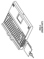
- FIG. 1 is a schematic view of a conventional notebook computer case having two horizontal slots on an outer wall;
- FIG. 2 is a partially exploded view of the notebook computer case showing two wired modular jacks in accordance with a preferred embodiment of the present invention
- FIG. 3 is a partially elevational view of the notebook computer case showing two wired modular jacks in accordance with a preferred embodiment of the present invention.
- FIG. 4 is a top plan view of the notebook computer case showing two wired modular jacks in accordance with a preferred embodiment of the present invention, in which the arrangement of the lower case, the jack insert and the printed circuit board having a built-in fax/modem card and/or a network card is shown.
- a notebook computer case 1 in accordance with the present invention comprises: a wired modular jack insert 2 , a lower case 4 and an upper case 6 .
- the wired modular jack insert 2 is substantially configured to a rectangular parallelepiped and comprises an insulation body 8 and a plurality of wires 10 .
- the body 8 has a front face 14 , a rear face 16 opposite to the front face 14 , a top face 18 connected between the front face 14 and the rear face 16 , a first side face 20 and a second side face 22 opposite to the first side face 20 .
- the first side face 20 and the second side face 22 connect with the front face 14 and the rear face 16 .
- the body 8 can be divided into two portions 24 , 26 wherein the first portion 24 is constructed as a portion of a RJ11 jack and the second portion 26 is constructed as a portion of a RJ45 jack.
- a protrusion 28 is formed on the top face 18 of the body 8 and extends from the front face 14 to the rear face 16 , which substantially separates the first portion 24 from the second portion 26 of the body 8 .
- a hole 30 is further formed on the protrusion 28 .
- Six parallel channels 32 arranged in two horizontal staggering rows are formed through the first portion 24 of the body 8 from the front face 14 to the rear face 16 . Further, eight parallel channels 34 also arranged in two horizontal staggering rows are formed through the second portion 26 of the body 8 from the front face 14 to the rear face 16 .
- the front face 14 of the body 8 is formed with a plurality of parallel grooves 36 thereon, each extending from one of the channels 32 , 34 to the top face 18 of the body 8 .
- a first indicative device 40 generally a light-emitting diode (LED)
- LED light-emitting diode
- a second indicative device 42 is provided on the front face 14 and adjacent to the first indicative device 40 for showing the power on/off status.
- Each of the wires 10 extends through the channels 32 or the channels 34 , and comprises a contact section 44 and a tail section 46 .
- the contact section 44 projects from the front face 14 of the body 8 and is folded upward along the groove 36 to the top face 18 and then rearward away from the front face 14 .
- the tail section 46 is embedded within the channels 32 , 34 and further projects from the rear face 16 to connect with a fax/modem card or network card built in a printed circuit board 12 (see FIG. 4 ). Even though there are six channels 32 provided in the first portion 24 , only two wires 10 are required for the conductive connection of a regular telephone line, as shown in FIGS. 2 and 3.
- the lower case 4 has a lower side frame 48 which has a top 50 and an outer wall 52 .
- the lower side frame 48 is configured to downward form a recess 54 from the top 50 thereof.
- the recess 54 of the lower side frame 48 is defined by two lateral walls 56 which are respectively provided with a vertical groove 58 for respectively receiving the vertical protrusion 38 of the body 8 and securing the body 8 in the lower side frame 48 of the lower case 4 . Accordingly, the body 8 is removably mounted within the recess 54 with the front face 14 substantially flush with the outer wall 52 of the lower case 4 .
- the upper case 6 has an upper side frame 56 which has a bottom 59 and an outer wall 60 . As the upper case 6 engages with the lower case 4 , the outer wall 60 of the upper side frame 56 is substantially flush with the outer wall 52 of the lower side frame 48 .
- the upper side frame 56 is configured to upward form two cavities 62 , 64 from the bottom 59 thereof.
- the upper side frame 56 of the upper case 6 is provided with a wall 66 separating the cavity 62 from the cavity 64 and aligned with the protrusion 28 of the top face 18 of the body 8 .
- the wall 66 is further provided with a post 68 for inserting into the hole 30 of the protrusion 28 on the top face 18 of the body 8 .
- the modular jack insert 2 and the cavities 62 , 64 define the modular jacks 68 , 70 respectively adapted for insertion of a plug.
- the alignment of the protrusion 28 and the wall 66 securely separates the two jacks 68 , 70 from each other.
- the modular jack 68 is used as a RJ11 jack and the modular jack 70 is used as a RJ45 jack.
- a combined RJ11/RJ45 modular jack is formed. Since the height of the modular jack is determined by the upper case, the jack insert and the lower case, the height of the notebook computer case can be significantly reduced as long as the dimensions thereof are properly determined. Further, since there is only one protrusion between the first portion and second portion, the space required for the jack can be reduced such that the additional ports can be provided on the same outer wall of the computer case.
- the above computer case is a preferred embodiment in accordance with the present invention.
- the computer case also be an integral case with a side wall which forms an opening for removably receiving the insert therein with the front face of the insert substantially flush with the side wall. Accordingly, when the insert is received within the opening, the modular jack insert and the opening define the modular jack adapted for insertion of a plug.
Abstract
Description
Claims (14)
Priority Applications (1)
| Application Number | Priority Date | Filing Date | Title |
|---|---|---|---|
| US09/825,541 US6587334B2 (en) | 2000-04-06 | 2001-04-03 | Notebook computer case with at least one wired modular jack |
Applications Claiming Priority (2)
| Application Number | Priority Date | Filing Date | Title |
|---|---|---|---|
| US19627600P | 2000-04-06 | 2000-04-06 | |
| US09/825,541 US6587334B2 (en) | 2000-04-06 | 2001-04-03 | Notebook computer case with at least one wired modular jack |
Publications (2)
| Publication Number | Publication Date |
|---|---|
| US20010036059A1 US20010036059A1 (en) | 2001-11-01 |
| US6587334B2 true US6587334B2 (en) | 2003-07-01 |
Family
ID=26891781
Family Applications (1)
| Application Number | Title | Priority Date | Filing Date |
|---|---|---|---|
| US09/825,541 Expired - Lifetime US6587334B2 (en) | 2000-04-06 | 2001-04-03 | Notebook computer case with at least one wired modular jack |
Country Status (1)
| Country | Link |
|---|---|
| US (1) | US6587334B2 (en) |
Citations (4)
| Publication number | Priority date | Publication date | Assignee | Title |
|---|---|---|---|---|
| US5186646A (en) * | 1992-01-16 | 1993-02-16 | Pederson William A | Connector device for computers |
| US5505633A (en) * | 1994-05-13 | 1996-04-09 | Intel Corporation | Integral external connector interface for thin form factor computer cards |
| US5562491A (en) * | 1990-09-17 | 1996-10-08 | Raychem Corporation | Gel filled electrical connector |
| US5704802A (en) * | 1996-06-14 | 1998-01-06 | Maxconn Incorporated | Modular jack assembly |
-
2001
- 2001-04-03 US US09/825,541 patent/US6587334B2/en not_active Expired - Lifetime
Patent Citations (4)
| Publication number | Priority date | Publication date | Assignee | Title |
|---|---|---|---|---|
| US5562491A (en) * | 1990-09-17 | 1996-10-08 | Raychem Corporation | Gel filled electrical connector |
| US5186646A (en) * | 1992-01-16 | 1993-02-16 | Pederson William A | Connector device for computers |
| US5505633A (en) * | 1994-05-13 | 1996-04-09 | Intel Corporation | Integral external connector interface for thin form factor computer cards |
| US5704802A (en) * | 1996-06-14 | 1998-01-06 | Maxconn Incorporated | Modular jack assembly |
Also Published As
| Publication number | Publication date |
|---|---|
| US20010036059A1 (en) | 2001-11-01 |
Similar Documents
| Publication | Publication Date | Title |
|---|---|---|
| US7708599B2 (en) | Card edge connector with power contacts | |
| US20090275240A1 (en) | Stacked electrical connector with improved contacts arrangement | |
| US7578696B2 (en) | Electrical connector with cover configured for heat dissipation | |
| US6416364B1 (en) | RJ-45 receptacle connector with terminal protection means | |
| US20100144179A1 (en) | Stacked card connector | |
| US20020076959A1 (en) | Card edge connector with safety ejector | |
| US7677903B1 (en) | Board-to-board connector assembly | |
| US20080032546A1 (en) | Modular jack with LED retention means | |
| US20070020966A1 (en) | Board shaped electrical connector | |
| WO2004107504A3 (en) | Back-end variation control cap for use with a jack module | |
| US7682161B2 (en) | Electrical connector having power terminals | |
| US7614905B2 (en) | Modular jack | |
| US7909655B2 (en) | Connector jack with reduced host PCB footprint assembly-thereof and fabrication method of the same | |
| US7351097B2 (en) | Electric connector with right-angled contacts | |
| US6579129B2 (en) | Connector assembly | |
| US7651343B2 (en) | Low profile electrical connector | |
| US6587334B2 (en) | Notebook computer case with at least one wired modular jack | |
| US6244905B1 (en) | Jack connector with reliably retained contacts | |
| US6736672B1 (en) | Stacked card connector having two rows of terminals extending out of a bottom surface of the connector at a side opposite to an insert port | |
| US6558197B1 (en) | Low profile modular jack | |
| US6461200B1 (en) | Electrical connector assembly | |
| US20010004567A1 (en) | Modular connector | |
| US6905345B2 (en) | Electrical connector assembly | |
| US6482044B1 (en) | Audio jack | |
| JP3120995U (en) | Card connector |
Legal Events
| Date | Code | Title | Description |
|---|---|---|---|
| AS | Assignment |
Owner name: BERG TECHNOLOGY, INC., NEVADA Free format text: ASSIGNMENT OF ASSIGNORS INTEREST;ASSIGNOR:CHEN, WEN-LIANG;REEL/FRAME:011935/0538 Effective date: 20010611 |
|
| STCF | Information on status: patent grant |
Free format text: PATENTED CASE |
|
| AS | Assignment |
Owner name: BANC OF AMERICA SECURITIES LIMITED, AS SECURITY AG Free format text: SECURITY AGREEMENT;ASSIGNOR:FCI AMERICAS TECHNOLOGY, INC.;REEL/FRAME:017400/0192 Effective date: 20060331 |
|
| AS | Assignment |
Owner name: FCI AMERICAS TECHNOLOGY, INC., NEVADA Free format text: CHANGE OF NAME;ASSIGNOR:BERG TECHNOLOGY, INC.;REEL/FRAME:017422/0729 Effective date: 20000808 |
|
| FPAY | Fee payment |
Year of fee payment: 4 |
|
| FPAY | Fee payment |
Year of fee payment: 8 |
|
| AS | Assignment |
Owner name: FCI AMERICAS TECHNOLOGY LLC, NEVADA Free format text: CONVERSION TO LLC;ASSIGNOR:FCI AMERICAS TECHNOLOGY, INC.;REEL/FRAME:025957/0432 Effective date: 20090930 |
|
| AS | Assignment |
Owner name: FCI AMERICAS TECHNOLOGY LLC (F/K/A FCI AMERICAS TE Free format text: RELEASE OF PATENT SECURITY INTEREST AT REEL/FRAME NO. 17400/0192;ASSIGNOR:BANC OF AMERICA SECURITIES LIMITED;REEL/FRAME:029377/0632 Effective date: 20121026 |
|
| FPAY | Fee payment |
Year of fee payment: 12 |