US6594094B2 - Read/write channel - Google Patents

Read/write channel Download PDF

Info

Publication number
US6594094B2
US6594094B2 US10/025,001 US2500101A US6594094B2 US 6594094 B2 US6594094 B2 US 6594094B2 US 2500101 A US2500101 A US 2500101A US 6594094 B2 US6594094 B2 US 6594094B2
Authority
US
United States
Prior art keywords
read
write
servo
mode
signal
Prior art date
Legal status (The legal status is an assumption and is not a legal conclusion. Google has not performed a legal analysis and makes no representation as to the accuracy of the status listed.)
Expired - Lifetime
Application number
US10/025,001
Other versions
US20020154430A1 (en
Inventor
James W. Rae
William Bliss
Jonathan Ashley
Razmik Karabed
Stephen J. Franck
Fritz Mistlberger
Matthias Driller
Heinrich Stockmanns
Dominik Margraf
Current Assignee (The listed assignees may be inaccurate. Google has not performed a legal analysis and makes no representation or warranty as to the accuracy of the list.)
Cavium International
Marvell Asia Pte Ltd
Original Assignee
Infineon Technologies North America Corp
Priority date (The priority date is an assumption and is not a legal conclusion. Google has not performed a legal analysis and makes no representation as to the accuracy of the date listed.)
Filing date
Publication date
Application filed by Infineon Technologies North America Corp filed Critical Infineon Technologies North America Corp
Priority to US10/025,001 priority Critical patent/US6594094B2/en
Assigned to INFINEON TECHNOLOGIES NORTH AMERICA CORP. reassignment INFINEON TECHNOLOGIES NORTH AMERICA CORP. ASSIGNMENT OF ASSIGNORS INTEREST (SEE DOCUMENT FOR DETAILS). Assignors: KARABED, RAZMIK, BLISS, WILLIAM, FRANCK, STEPHEN J., ASHLEY, JONATHAN, DRILLER, MATTHIAS, MARGRAF, DOMINIK, RAE, JAMES W., STOCKMANNS, HEINRICH, MISTLBERGER, FRITZ
Publication of US20020154430A1 publication Critical patent/US20020154430A1/en
Application granted granted Critical
Publication of US6594094B2 publication Critical patent/US6594094B2/en
Assigned to INFINEON TECHNOLOGIES AG reassignment INFINEON TECHNOLOGIES AG ASSIGNMENT OF ASSIGNORS INTEREST (SEE DOCUMENT FOR DETAILS). Assignors: INFINEON TECHNOLOGIES NORTH AMERICA CORP.
Assigned to MARVELL INTERNATIONAL LTD. reassignment MARVELL INTERNATIONAL LTD. ASSIGNMENT OF ASSIGNORS INTEREST (SEE DOCUMENT FOR DETAILS). Assignors: INFINEON TECHNOLOGIES AG
Assigned to CAVIUM INTERNATIONAL reassignment CAVIUM INTERNATIONAL ASSIGNMENT OF ASSIGNORS INTEREST (SEE DOCUMENT FOR DETAILS). Assignors: MARVELL INTERNATIONAL LTD.
Assigned to MARVELL ASIA PTE, LTD. reassignment MARVELL ASIA PTE, LTD. ASSIGNMENT OF ASSIGNORS INTEREST (SEE DOCUMENT FOR DETAILS). Assignors: CAVIUM INTERNATIONAL
Anticipated expiration legal-status Critical
Expired - Lifetime legal-status Critical Current

Links

Images

Classifications

    • GPHYSICS
    • G11INFORMATION STORAGE
    • G11BINFORMATION STORAGE BASED ON RELATIVE MOVEMENT BETWEEN RECORD CARRIER AND TRANSDUCER
    • G11B20/00Signal processing not specific to the method of recording or reproducing; Circuits therefor
    • G11B20/10Digital recording or reproducing
    • G11B20/10009Improvement or modification of read or write signals
    • G11B20/10046Improvement or modification of read or write signals filtering or equalising, e.g. setting the tap weights of an FIR filter
    • G11B20/10055Improvement or modification of read or write signals filtering or equalising, e.g. setting the tap weights of an FIR filter using partial response filtering when writing the signal to the medium or reading it therefrom
    • GPHYSICS
    • G11INFORMATION STORAGE
    • G11BINFORMATION STORAGE BASED ON RELATIVE MOVEMENT BETWEEN RECORD CARRIER AND TRANSDUCER
    • G11B20/00Signal processing not specific to the method of recording or reproducing; Circuits therefor
    • G11B20/10Digital recording or reproducing
    • G11B20/10009Improvement or modification of read or write signals
    • G11B20/10037A/D conversion, D/A conversion, sampling, slicing and digital quantisation or adjusting parameters thereof
    • GPHYSICS
    • G11INFORMATION STORAGE
    • G11BINFORMATION STORAGE BASED ON RELATIVE MOVEMENT BETWEEN RECORD CARRIER AND TRANSDUCER
    • G11B5/00Recording by magnetisation or demagnetisation of a record carrier; Reproducing by magnetic means; Record carriers therefor
    • G11B5/02Recording, reproducing, or erasing methods; Read, write or erase circuits therefor
    • G11B5/09Digital recording
    • GPHYSICS
    • G11INFORMATION STORAGE
    • G11BINFORMATION STORAGE BASED ON RELATIVE MOVEMENT BETWEEN RECORD CARRIER AND TRANSDUCER
    • G11B5/00Recording by magnetisation or demagnetisation of a record carrier; Reproducing by magnetic means; Record carriers therefor
    • G11B5/48Disposition or mounting of heads or head supports relative to record carriers ; arrangements of heads, e.g. for scanning the record carrier to increase the relative speed
    • G11B5/58Disposition or mounting of heads or head supports relative to record carriers ; arrangements of heads, e.g. for scanning the record carrier to increase the relative speed with provision for moving the head for the purpose of maintaining alignment of the head relative to the record carrier during transducing operation, e.g. to compensate for surface irregularities of the latter or for track following
    • G11B5/60Fluid-dynamic spacing of heads from record-carriers
    • G11B5/6005Specially adapted for spacing from a rotating disc using a fluid cushion
    • G11B5/6011Control of flying height
    • G11B5/6076Detecting head-disk contact
    • GPHYSICS
    • G11INFORMATION STORAGE
    • G11BINFORMATION STORAGE BASED ON RELATIVE MOVEMENT BETWEEN RECORD CARRIER AND TRANSDUCER
    • G11B5/00Recording by magnetisation or demagnetisation of a record carrier; Reproducing by magnetic means; Record carriers therefor
    • G11B5/012Recording on, or reproducing or erasing from, magnetic disks
    • GPHYSICS
    • G11INFORMATION STORAGE
    • G11BINFORMATION STORAGE BASED ON RELATIVE MOVEMENT BETWEEN RECORD CARRIER AND TRANSDUCER
    • G11B5/00Recording by magnetisation or demagnetisation of a record carrier; Reproducing by magnetic means; Record carriers therefor
    • G11B5/48Disposition or mounting of heads or head supports relative to record carriers ; arrangements of heads, e.g. for scanning the record carrier to increase the relative speed
    • G11B5/58Disposition or mounting of heads or head supports relative to record carriers ; arrangements of heads, e.g. for scanning the record carrier to increase the relative speed with provision for moving the head for the purpose of maintaining alignment of the head relative to the record carrier during transducing operation, e.g. to compensate for surface irregularities of the latter or for track following
    • G11B5/596Disposition or mounting of heads or head supports relative to record carriers ; arrangements of heads, e.g. for scanning the record carrier to increase the relative speed with provision for moving the head for the purpose of maintaining alignment of the head relative to the record carrier during transducing operation, e.g. to compensate for surface irregularities of the latter or for track following for track following on disks
    • G11B5/59688Servo signal format patterns or signal processing thereof, e.g. dual, tri, quad, burst signal patterns

Definitions

  • the present invention relates to disk drives and, particularly, to an improved read/write channel.
  • data are encoded and written onto a disk in regions of differing magnetization. To read the data out, they are first detected and then decoded. The writing and reading occurs using a magnetic head, such as inductive heads or magneto-resistive heads.
  • FIG. 54 illustrates an exemplary read-write channel system according to the prior art.
  • the system includes an encoder 5402 , read/write head 5404 , disk 5406 , detector 5408 , and decoder 5410 .
  • User data are provided to the encoder 5402 .
  • the input data may be subject to further channel or modulation coding, as well as error correction coding, and are then written onto the disk 5406 by the head 5404 .
  • the bits are converted into a write current waveform.
  • the write current waveform takes a positive value, it magnetizes the disk in a first direction; when negative, it magnetizes the disk in a second direction.
  • These states of magnetization are typically described using NRZ or NRZI data.
  • a one (1) represents one direction of magnetization, and a zero (0) represents another.
  • a one (1) identifies a transition, and a zero (0) represents no transition.
  • the data prior to converting the data to the magnetization pattern, it is typically encoded (e.g., using encoder 5402 ).
  • the encoding typically minimizes the number of adjacent transitions (to reduce intersymbol interference) and to avoid long strings of zeroes (which can cause problems with channel synchronization and detection.). Coding types include run length limited codes and other known types.
  • the head reads an analog signal and provides it to the detector 5408 .
  • detectors are commonly used. These include peak detectors or sampled data detection techniques.
  • the detector 5408 recovers the data and provides it to the decoder 5410 , which decodes the channel data.
  • the readback signal is filtered and sampled at a channel rate of 1/T, where T is the duration of a channel symbol.
  • T is the duration of a channel symbol.
  • PRML partial response with maximum likelihood
  • PRML systems the output of the noisy partial response channel is sampled at the channel rate and detected using a maximum likelihood Viterbi detector.
  • the partial response channel has a transfer function of the form (1 ⁇ D)(1+D) or 1 ⁇ D 2 , where D represents a unit time delay operator with unit-time T.
  • D represents a unit time delay operator with unit-time T.
  • the extended partial response with maximum likelihood (EPRML) channel has a transfer function of the form (1 ⁇ D)(1+D) 2 or (1+D ⁇ D 2 ⁇ D 3 ).
  • the noiseless output of the extended partial response channel is equal to the input signal minus a version of the input signal delayed in time by 2T, minus a version of the input signal delayed in time by 3T and plus a version of the input signal delayed in time by T.
  • the E 2 PRML channel has a transfer function of the form (1 ⁇ D)(1+D) 3 .
  • Viterbi decoders are typically employed in sampled amplitude channels. Viterbi decoders are specific implementation of the Viterbi algorithm.
  • a Viterbi detector unit is based on periodic examination of metrics associated with alternate sequences of recorded bits, wherein each sequence is typically labeled as a “path” and the associated metric is designated a “path metric.” The most probable correct path is then determined by choosing a minimum path metric based on an iterative process involving successive comparison of associated path metrics.
  • an improved sampled amplitude read/write channel is provided.
  • the system is an integrated Generalized Partial Response Maximum Likelihood (GPRML) read channel incorporating Read, Write, and Servo modes of operation.
  • GPRML Generalized Partial Response Maximum Likelihood
  • One implementation includes a 32/34 rate parity code and matched Viterbi detector, a 32 state Viterbi detector optimal parity processor, robust frame synchronization, self-adaptive equalization, thermal asperity detection and compensation, adaptive magneto-resistive asymmetry compensation, low latency interpolated timing recovery and programmable write precompensation.
  • FIG. 1 is a block diagram of a read/write channel according to a specific embodiment of the invention.
  • FIG. 2 is a diagram input impedance switches according to an embodiment of the invention.
  • FIG. 3 is a diagram of thermal asperity detection and correction according to an embodiment of the invention.
  • FIG. 4 is a diagram of thermal asperity correction waveforms according to an embodiment of the invention.
  • FIG. 5 is a diagram of MR Asymmetry compensation according to an embodiment of the invention.
  • FIG. 6 is a diagram of a timing control subsystem according to an embodiment of the invention.
  • FIG. 7 is a diagram of a timing loop filter according to an embodiment of the invention.
  • FIG. 8 is a diagram of timing acquisition according to an embodiment of the invention.
  • FIG. 9 is a diagram of an AGC loop according to an embodiment of the invention.
  • FIG. 10 is a diagram of an AGC loop filter according to an embodiment of the invention.
  • FIG. 11 is a diagram of a DC restore loop according to an embodiment of the invention.
  • FIG. 12 is a diagram of AGC shadow register operation in read mode according to an embodiment of the invention.
  • FIG. 13 is a diagram of AGC shadow register operation in servo mode according to an embodiment of the invention.
  • FIG. 14 is a diagram of DC restore shadow register operation according to an embodiment of the invention.
  • FIG. 15 is a diagram of an MR Asymmetry compensation loop according to an embodiment of the invention.
  • FIG. 16 is a diagram of MR Asymmetry shadow register operation according to an embodiment of the invention.
  • FIG. 17 is a diagram of FIR filter structure according to an embodiment of the invention.
  • FIG. 18 is a diagram of FIR adaptation according to an embodiment of the invention.
  • FIG. 19 is a diagram of FIR Adaptation Read Mode Timing according to an embodiment of the invention.
  • FIG. 20 is a diagram of a Viterbi detector according to an embodiment of the invention.
  • FIG. 21 is a write path block diagram according to an embodiment of the invention.
  • FIG. 22 is a scrambler/descrambler block diagram according to an embodiment of the invention.
  • FIG. 23 is a diagram of a PRBS generator according to an embodiment of the invention.
  • FIG. 24 is a block diagram of a precoder according to an embodiment of the invention.
  • FIG. 25 is a diagram of write precomp according to an embodiment of the invention.
  • FIG. 26 is a write PECL interface according to an embodiment of the invention.
  • FIG. 27 is a diagram of PECL logic levels according to an embodiment of the invention.
  • FIG. 28 is a block diagram of a digital servo according to an embodiment of the invention.
  • FIG. 29 is a block diagram of a correlator according to an embodiment of the invention.
  • FIG. 30 is a diagram of a correlator frequency response according to an embodiment of the invention.
  • FIG. 31 is a timing diagram of unoriented search (manual AGC) according to an embodiment of the invention.
  • FIG. 32 is a timing diagram of unoriented search (auto sample AGC) according to an embodiment of the invention.
  • FIG. 33 is a timing diagram of oriented search (normal AGC) according to an embodiment of the invention.
  • FIG. 34 is a diagram of servo address mark polarity according to an embodiment of the invention.
  • FIG. 35 is a diagram of NRZI read interface timing according to an embodiment of the invention.
  • FIG. 36 is a diagram of NRZI write interface timing according to an embodiment of the invention.
  • FIG. 37 is a diagram of a read mode/write mode PLL according to an embodiment of the invention.
  • FIG. 38 is a diagram of a servo mode PLL according to an embodiment of the invention.
  • FIG. 39 is a diagram of serial port timing according to an embodiment of the invention.
  • FIG. 40 is a diagram of read mode sector architecture according to an embodiment of the invention.
  • FIG. 41 is a diagram of read mode operation acquire timing according to an embodiment of the invention.
  • FIG. 42 is a diagram of read mode gate extension according to an embodiment of the invention.
  • FIG. 43 is a diagram of normal write operation according to an embodiment of the invention.
  • FIG. 44 is a diagram of direct write operation according to an embodiment of the invention.
  • FIG. 45 is a diagram of system operation according to an embodiment of the invention.
  • FIG. 46 is a diagram of write mode to idle mode recovery according to an embodiment of the invention.
  • FIG. 47 a and FIG. 47 b illustrate channel quality measurements according to an embodiment of the invention
  • FIG. 48 illustrates a measurement interval timer state machine according to an embodiment of the invention
  • FIG. 49 illustrates CQM data collection—single sector according to an embodiment of the invention
  • FIG. 50 illustrates CQM data collection—multiple sectors according to an embodiment of the invention
  • FIG. 51 illustrates analog signal injection according to an embodiment of the invention
  • FIG. 52 illustrates a view ADC function according to an embodiment of the invention
  • FIG. 53 illustrates an analog test port according to an embodiment of the invention.
  • FIG. 54 is a diagram of a read-write channel system according to the prior art.
  • the modulation code used in one embodiment of the invention is a rate 32/34 block code. All 34-bit codewords satisfy a ‘Charge module 2’ (Qmod2) parity constraint. The code achieves about 1 dB net coding gain by forcing the charge in each codeword to be even. As a consequence of this parity constraint, all error sequences with odd parity are eliminated. This includes; di-bit drop-in and drop-outs (0,+1 0), tri-bit related errors (+1, ⁇ 1, +1), pentabit related errors (+1, ⁇ 1, +1 , ⁇ 1 , +1), etc.
  • the (Qmod2 constraint offers more immunity to errors than uncoded or maximum transition run (MTR) codes under normal operating environments.
  • the modulation code is also designed to achieve good worst-case timing information, maximizing the minimum timing information content in any codeword.
  • Each 34 bit codeword has at least a minimum of 7 timing units of information.
  • minimum-distance error events on the coded trellis are limited to cause errors in no more than 4 decoded user bytes.
  • best system performance is achieved using an outer error correcting code with 8-bit symbols, GF(256), and with greater than or equal to 4-way interleave.
  • Table 1 Code Properties
  • the sequence detector is implemented using a 32-state Viterbi detector that is the product of a 16-state Noise-Predictive Inter-Symbol Interference (NP ISI) Viterbi algorithm and a 2-state time-varying charge parity trellis.
  • the 32-state product trellis is pruned back to 16-states at every 34th bit-cycle to enforce the charge parity constraint at the block boundary.
  • This implementation of the parity code is an optimal maximum likelihood solution, and has none of the sub-optimal characteristics of prior solutions, e.g., failure at block boundaries, sensitivity to changing error event structure, etc.
  • the system allows the user to choose from four different noise-predictive Viterbi algorithms.
  • Noise Predictive (3,2,1 ⁇ is best suited for applications with low to moderate user densities. It performs well in these areas even with high media noise.
  • Noise Predictive (2,2, 1 ⁇ is best suited for applications with moderate media noise and moderate to high user densities.
  • Noise Predictive (3,1, 1 ⁇ is best suited for applications with low to moderate user density and very high media noise.
  • EPR4 is included as a legacy mode, and performs close to Noise Predictive ⁇ 3,2,1 ⁇ in most environments.
  • Exemplary Viterbi detection is described in commonly assigned U.S. patent application Ser. No. 09/347,598, filed Jul. 1, 1999, titled “Trellis Code for EPRML”, U.S. patent application Ser. No. 09/465,521, filed Dec. 16, 1999, titled “Survival Selection Rule,” and U.S. patent application Ser. No. 09/503,534, filed Feb. 14, 2000, titled “Supporting ME2PRML and M2EPRML with the Same Trellis Structure,” which are hereby incorporated by reference in their entireties as if fully set forth herein.
  • FIG. 1 a block diagram of a read/write channel according to a specific embodiment of the invention is shown therein and designated generally by the reference numeral 100 .
  • the system 100 is operable in a plurality of modes, selectable with the inputs RGATE, WGATE, SGATE, and the mode control unit 102 .
  • the modes are Read Mode, Write Mode, Normal Write Mode, Known Data Write Mode, Write Mode During Servo Mode, Servo Mode, Idle Mode, Doze Mode, and Suspend Mode.
  • the operating modes of the read/write channel are determined by the state of five pins: RGATE, WGATE, SGATE, PWRDN, NRESET, and two registers: 04 ⁇ 2>, and 04 ⁇ 1>.
  • the operating modes are shown in Table 2:
  • RGATE In the read mode, RGATE is asserted, and the read channel is activated. In the read channel, a bit sequence is provided via thermal asperity compensation 104 to a variable gain amplifier 106 to adjust the amplitude of the signal.
  • DC offset control 130 and loop filter/gain error correction 131 also may be provided.
  • an asymmetry control unit 132 including an asymmetry adjustment unit 134 and asymmetry control 136 may be provided to compensate for magneto-resistive asymmetry effects.
  • An exemplary system for magneto-resistive asymmetry control is described in co-pending U.S. patent application Ser. No. 09/546,796, filed Apr. 11, 2000, titled “Magneto-Resistive Asymmetry Control Loop”, which is hereby incorporated by reference in its entirety as if fully set forth herein.
  • the signal is provided to a continuous time filter 110 , such as a four pole Butterworth filter, for example, to attenuate high frequency noise and minimize aliasing into baseband after sampling.
  • the signal is then provided to an analog to digital converter (ADC) 112 to sample the output of the continuous time filter (CTF) 110 .
  • ADC analog to digital converter
  • a finite impulse response (FIR) filter 114 provides additional equalization of the signal to the desired response.
  • the output of the FIR 114 is provided to an interpolated timing recovery unit 116 , which is used to recover the discrete time sequence.
  • Exemplary timing recovery is described in commonly assigned U.S. patent application Ser. No. 09/497,301, filed Feb. 2, 2000, titled “Asynchronous Timing for Interpolated Timing Recovery,” and U.S. patent application Ser. No. 09/496,617, filed Feb. 2, 2000, titled “Synchronous Timing for Interpolated Timing Recovery,” which are hereby incorporated by reference in their entireties as if fully set forth herein.
  • the output of the interpolated timing recovery unit 116 is used to provide a feedback control to the DC offset control 130 , the gain error 131 , the asymmetry control 132 and the FIR 114 .
  • the output of the interpolated timing recovery 116 is further provided to a Viterbi detector 120 and a sync detector 118 .
  • Sync mark information is then provided to the Viterbi detector 120 for use in sequence detection.
  • the Viterbi detector output is then provided to the decoder 121 which decodes the encoding provided by the encoder (not shown). Exemplary sync mark detection is described in U.S.
  • sync byte detector 118 is programmably polarity sensitive such that the polarity of the data stream entering the sync detector and the Viterbi detector may be flipped. Exemplary acquisition signal estimation is described in U.S. patent Ser. No. 09/653,235, filed Aug. 31, 2000, titled “An Acquisition Signal Error Estimator,” which is hereby incorporated by reference in its entirety as if fully set forth herein.
  • write data are provided to as NRZIO data to the interface 122 , then are scrambled and encoded in unit 123 , then serialized and precoded using serializer/precoder 124 , and precompensated using precomepnsator 126 .
  • the write data are then provided to a PECL driver 127 .
  • WGATE In the Normal Write Mode, WGATE is asserted and the disk drive controller (not shown) clocks a 00h (hex) byte to the NRZIO interface 122 .
  • the device output is a 2T preamble pattern until the data marker, a FFh byte, is received from the controller. At that point, the device inserts a unique sync byte into the output data stream, which replaces the received FFh byte.
  • Subsequent data transferred from the controller is scrambled, encoded ( 123 ) and then transferred to the PECL interface 127 as encoded user data.
  • the Known Data Write mode is a variation of a normal Write.
  • the device write output is a sector of internally generated data.
  • the operation begins when WGATE is asserted and the controller clocks a 00h (hex) byte to the NRZIO interface 122 .
  • the device writes a 2T preamble pattern until the data marker, a FFh byte, is received from the controller.
  • the device inserts a unique sync-byte into the output data stream, which replaces the received FFh byte, followed by write data consisting of an internally generated repeating pseudo-random binary sequence (PRBS), the output of a linear feedback shift register (LFSR) circuit.
  • PRBS internally generated repeating pseudo-random binary sequence
  • LFSR linear feedback shift register
  • the VGA and AGC loops, as well as the CTF, 110 ADC 112 , and FIR filter 114 sections of the read path are active, and are programmed to a unique set of servo register values.
  • the equalized and conditioned sample values are sent to a servo synchronizer that functions to determine time intervals needed for digital based asynchronous peak detection.
  • Asynchronous peak detection is used to determine the peak position required to demodulate the Gray code.
  • a and B servo bursts are digitally integrated to produce burst area estimates that are transferred to the disk controller via the NRZIO interface 122 .
  • Idle Mode is defined as the absence of Read mode, Write mode and Servo mode activity. All analog circuitry and frequency synthesizers are enabled, and the analog to digital converter (ADC) and DC Restore are active.
  • ADC analog to digital converter
  • Register bits 98 ⁇ 1:0> and 98 ⁇ 1:0> determine if the synthesizers are enabled. Upon transition from Doze Mode to Idle Mode, a start-up time is required to allow the frequency synthesizers and analog circuitry to stabilize.
  • the timing rules are defined in Table 3.
  • Suspend Mode turns off all channel read/write activity.
  • the system device may be divided into functional partitions that may be powered on or off depending on which mode is active. In the following table, 1 is powered-on, and 0 is powered-off.
  • the read path includes differential input pins VIN_P, VIN_N, thermal asperity and compensation unit 104 , VGA 106 , MR asymmetry compensation 108 , continuous time filter (CTF) 110 , analog-to-digital converter (ADC) 112 , finite impulse response filter (FIR) 114 , interpolated timing recovery unit (ITR) 116 , Viterbi detector 120 , decoder 121 , and interface 122 , as well as associated feedback and control circuitry.
  • CTF continuous time filter
  • ADC analog-to-digital converter
  • FIR finite impulse response filter
  • ITR interpolated timing recovery unit
  • a differential signal from a preamplifier is transferred to the VGA 106 through the VIN_P and VIN_N pins.
  • External capacitors (not shown) couple the preamplifier signal to the VGA 106 .
  • the VGA inputs are internally biased so that external DC biasing components are not required.
  • the normal operating signal input level at pins VIN_P and V 1 N_N is 40-400 mV peak-to-peak differential.
  • An internal 8-bit DAC that is adjusted by the Automatic Gain Control (AGC) loop (described below) controls the gain of the VGA 106 .
  • the initial gain for read and servo operations are programmed as 2s-complement numbers in registers 7A ⁇ 7:0> and 7B ⁇ 7:0>, respectively.
  • the VGA control range is from 0 dB to 20 dB.
  • Impedance switches 202 , 208 in series and in parallel with the inputs of the VGA 106 , are shown in FIG. 2 . These switches allow reduced recovery time from transients that occur during write sequences and thermal asperity events. During a normal Read mode operation, the series switches 202 , 208 are closed and the shunt switch 210 is opened, setting the input impedance to 250-2000 Ohms.
  • the AC coupling pole frequency is increased by adjusting the shunt impedance ZADJ 210 to reduce the input impedance.
  • the input impedance is varied dynamically over time.
  • thermal asperity (TA) detection and correction Prior to being input to the VGA 106 , in certain embodiments, thermal asperity (TA) detection and correction is provided.
  • FIG. 3 illustrates an exemplary thermal asperity detection and correction unit or circuit 104 .
  • a TA Detection and Correction Unit 104 includes a TA Detect Unit 306 , a TA Control Unit 304 , and a TA Compensation Unit 302 .
  • the TA detection and correction circuitry 104 acts to reduce the effects of distortion caused when the magneto-resistive (MR) head encounters a TA on the disk.
  • MR magneto-resistive
  • the overall objective of the TA compensation circuit 104 is to reduce overload and decrease recovery time during a TA event. Ideally, the bit length of the compensated error burst will be reduced so that ECC correction is possible.
  • the TA detect block 306 includes a lowpass filter (not shown) coupled to a threshold detector (not shown).
  • the amplitude-normalized signal from the output of the VGA 106 is sent through the TA detect low-pass filter and then applied to the threshold detector.
  • the threshold level is independently programmable for Read mode and Servo modes by using registers 89 ⁇ 3:0> and 39 ⁇ 7:4> respectively.
  • a TA event is defined to have occurred when the low-pass filter output exceeds the threshold value for the time set by register 88 ⁇ 5:4>.
  • the TA_OUT pin is asserted by the TA Control unit 304 .
  • an internal compensation sequence is initiated in the TA Compensation Unit 302 that changes the input high-pass pole frequency at the VGA input as described in FIG. 4 .
  • the input time-constant decays exponentially over a time period, set by T T , to the initial nominal value.
  • the gain of the DC restore loop 130 is also increased to allow for faster baseline recovery. Timing, gain and FIR adaptation loops are put in hold mode for the duration of the TA event.
  • the MR asymmetry loop is put in hold mode until the end of the RGATE. External or internal TA detection may be selected by register 88 ⁇ 7>. Relevant user programmable parameters are shown in Table 5:
  • the output of the VGA 106 is provided to a Magneto-resistive Asymmetry Compensation Unit (MRACU) 108 .
  • the MRACU 108 includes a squaring function 502 , a scaling multiplier function 504 , and an adder 506 .
  • the output of the VGA 106 is squared by the squaring function 502 and multiplied by the scaling factor Vmr in scaling multiplier 504 , and then added to itself using adder 506 .
  • This combination provides a nonlinear transfer function from the VGA 106 to the input of the continuous time filter (CTF) 110 in a form that may be adjusted to compensate for second harmonic distortion created by the MR head.
  • the term Vmr adjusts the magnitude of compensation.
  • the value of Vmr is automatically determined by an MR asymmetry compensation loop as will be described below with reference to FIG. 15 .
  • An adder function 109 following the compensation circuit 108 is used to nullify the accumulated DC offset in the analog signal path.
  • a voltage, Vdc derived from a DC restore control loop (described in greater detail below, with reference to FIG. 11 ), is added to the signal to cancel the DC value of the signal into the CTF 110 and ADC 112 .
  • the DC restore control loop is implemented in the digital domain.
  • the CTF 110 in one implementation is a 4-pole continuous time low pass analog filter and is used to truncate the noise bandwidth input to the analog to digital converter (ADC) 112 .
  • the low pass characteristic also prevents aliased frequency components beyond the Nyquist frequency from falling in the pass band.
  • the frequency response of the filter does not correspond to a standard polynomial.
  • ⁇ 0 pole-pair frequency
  • Q pole-pair quality factor
  • the ADC 112 is a 6-bit, background calibrated, flash ADC.
  • the use of an interpolated timing recovery architecture allows more channel latency. The latency may be exploited to optimize speed, power and performance in the design of the ADC.
  • the system uses a digital interpolated timing recovery (ITR) method to resample readback waveform samples at the proper time instances required for sequence detection.
  • ITR digital interpolated timing recovery
  • FIG. 6 shows the phase-locked loop structure that is used to synchronize to the phase and frequency of the incoming readback bit stream.
  • asynchronous samples from the FIR 114 are provided to an 8-tap interpolation filter 602 .
  • the interpolated samples are then provided in a loop including a timing error unit 119 , a first order loop filter 117 , and a timing accumulator base and phase calculator 602 .
  • the timing accumulator 602 also receives an input from a zero phase restart unit 604 .
  • the equalized and oversampled data values from the ADC are interpolated using a 8-tap digital FIR interpolation filter.
  • the sample phase is represented as a binary number which is the input to the interpolation filter.
  • the Timing Error block 119 processes interpolated samples to produce the timing corrections that are used for tracking and acquisition modes respectively.
  • the errors are filtered by a digital pole-zero filter 117 combination to produce the estimated error in interpolation sample time.
  • the “Time Accum” block 602 translates its input into two signals: the resample phase within a clock cycle, and uk, which acts as a not-strobe to indicate when a clock period does not contain a resample. When mk is asserted, the ITR output for the corresponding clock cycle is ignored for all downstream processing.
  • the 8-tap filter 602 estimates the sample value between the asynchronous samples to produce time-normalized interpolated sample values. Since the device uses a 6.67% oversampling ratio, approximately every 16th clock cycle is not used.
  • the timing loop filter 117 is synthesized in the digital domain.
  • a block diagram of the 1st order digital loop filter 117 is described in FIG. 7 .
  • the timing loop filter output is the sum of a digital integrator 701 , representing a pole, and a roportional term ⁇ 704 , representing a zero.
  • the integrator 701 includes a caling factor ⁇ , accumulator register R 708 and feedback adder 706 .
  • the contributions of the pole and zero are dynamically changed during the ock-on sequence by varying ⁇ and ⁇ to minimize phase and frequency capture time.
  • the upper path 701 containing integrating register R 708 , stores the resampled frequency setting while the lower path 704 causes phase adjustments that are required for loop stability and for reduction of peak phase errors.
  • the timing algorithm proceeds through three distinct modes.
  • the three timing mode intervals are shown pictorially in FIG. 8 : a “zero-phase” mode 802 , where the resampling phase is set to a predetermined value with respect to the average phase of the preamble, a second “fast-acquire” mode 806 , where the frequency of the loop is adjusted, and a third and final “data-tracking” mode 808 , where the timing loop is phase and frequency locked and the timing corrections are derived by averaging over many bits. This is sometimes called the three gear system.
  • the AGC loop shown in FIG. 9, sets the overall voltage gain of the read path so that the output amplitude of the ADC 112 is independent of channel input voltage variations.
  • the function of the AGC loop is to provide a normalized signal amplitude input for the Viterbi detector 120 .
  • the AGC loop also functions to constrain the signal voltage to be within the dynamic range of the ADC 113 .
  • Gain corrections, Gn are derived from interpolator output samples, x.
  • the loop filter 131 includes integrator having an adder 1002 , register 1004 and D/A 1006 .
  • the gain register 1004 , R accumulates gain error terms until the control voltage to the VGA stage VAGC, is set to the value that makes the amplitude input to the Viterbi detector 120 equal to the target number.
  • the loopfilter includes an integrator having an adder 1102 , register 1104 and D/A 1106 .
  • an error term, e is calculated and added to the accumulator value R 1104 which is coupled to a DAC 1106 .
  • the DAC output adds a correcting voltage to the analog signal path before the CTF 110 using adder 109 .
  • the control loop functions to nullify DC offset as measured at the ITR output.
  • the initialization of the register R 1004 used in the AGC is accomplished using a corresponding shadow register, as illustrated in FIG. 12 . Shown are states 1202 and 1204 . Shadow register operation is as follows: The AGC accumulator R 1004 is always loaded with the contents of the AGC shadow register when RGATE is asserted ( 1202 ). The shadow register can be loaded or read back ( 1204 ) by the serial interface. Alternately, when 78 ⁇ 1> is set, the shadow register is used to save the contents of the AGC accumulator 1004 at the deassertion of RGATE.
  • the shadow register is loaded with a ‘best guess” initial gain setting through the serial interface. Successive read cycles are performed with 78 ⁇ 1> set to 1, so that a new initial gain setting is saved after each sector. When the gain setting has converged and is no longer changing, the new value is saved and used as the initial gain setting for non-feedback AGC modes, when 78 ⁇ 1> is set to 0.
  • the initialization of the register R ( 1104 ) used in the DC restore (DCR) loop (FIG. 11) is accomplished using a corresponding shadow register, as shown in FIG. 14 .
  • the DCR accumulator R ( 1104 ) is always loaded with the contents of the read AGC shadow register when RGATE is asserted ( 1406 ).
  • the shadow register can be loaded or read-back by means of the serial interface ( 1408 ).
  • the read shadow register is used to save the contents of the AGC accumulator at the de-assertion of RGATE ( 1402 ).
  • the DCR accumulator R ( 1104 ) is always loaded with the contents of the servo shadow register when SGATE is asserted ( 1406 ).
  • the DCR servo shadow register is initialized either by the serial interface, or if register 78 ⁇ 2> is set, then it is loaded with the results of a previous read operation.
  • the MR asymmetry compensation loop operates only during the user data portion of the sector in Read mode.
  • the compensation ioop architecture is shown in FIG. 15, essentially the circuit of FIG. 5 with the input to the multiplier 506 shown as including summer 1502 , accumulator register R 1504 , and D/A 1506 .
  • An asymmetry error term, en derived from three consecutive sample values of the data, is added to the MR asymmetry accumulator R 1504 that accumulates to a value Mn.
  • the accumulator 1504 drives a DAC 1506 , producing an output, Vmr that is used to vary the value of V 2 vga, a signal proportional to the square of the analog output of the VGA 106 .
  • the output of the MR asymmetry compensation circuit becomes (Vvga+Vmr ⁇ V 2 vga).
  • the feedback loop adjusts the amplitude of (Imr ⁇ V 2 vga) to a value that will compensate for the 2 nd harmonic distortion produced by the MR head nonlinear transfer function.
  • the loop gain, ⁇ mr has only one setting.
  • Use and operation of the MR shadow register is identical to that of the DC restore shadow register (FIG. 14 ).
  • the FIR 114 is a 10-tap Finite Impulse Response Filter (FIR) and is used to complete the equalization of the digitized signal to the EPRML target waveform.
  • the topology of the filter is shown in FIG. 17 .
  • the active FIR coefficients (tap weights) 1700 - 1709 may be loaded with the contents of the shadow coefficient registers at the start of read or servo operations.
  • Two sets of shadow registers are used, one for Read mode and one for Servo mode, as shown in FIG. 18 .
  • the values of the Read mode and Servo mode FIR shadow registers ( 1802 , 1804 ) can be modified through the serial port when NOT in Read mode or Servo mode.
  • Only the read shadow registers 1802 can be updated with values derived from a self-adaptive read operation.
  • the values of the Servo mode shadow registers 1802 are always assigned through the serial port.
  • the FIR coefficients are transferred from the shadow registers to the F1R coefficient registers 1806 on assertion of RGATE.
  • values of the Read shadow registers 1804 are updated by the contents of the FIR coefficients derived from the previous read operation.
  • the FIR_SAT signal is asserted, indicating that one or more FIR filter coefficients have saturated, then the update is aborted and inaccurate coefficients are discarded.
  • selected filter taps may be programmed to serve as cursor taps by registers 30 ⁇ 7:0> and 30 ⁇ 0>. Selected taps retain their initial coefficient settings while other taps are adapted. This technique prevents unintended phase and amplitude shifts while the filter is adapting. There are no restrictions on which taps or how many taps can be defined as cursor taps.
  • the FIR filter operates in fixed mode with a fixed set of coefficients.
  • the FIR filter In Servo mode, the FIR filter only operates with a fixed set of coefficients, which are loaded from the servo shadow registers at the assertion of SGATE.
  • the de-interpolated estimate of the amplitude sample error and an estimate of the sample are used to calculate an equalizer error term that is used to adjust the individual tap coefficients of the FIR filter 114 .
  • FIR tap coefficients may be found by using an enhanced algorithm.
  • Known-data is used instead of estimated data to calculate equalizer error.
  • 20 ⁇ 3> bit is set to 1 and the data sector is written using a known-data write. Since no user data is transferred through the NRZIO interface 122 , this mode is used to only to find reliable FIR coefficients which in turn, may be used to preset the FIR equalizer during normal operation.
  • FIR tap adaptation is enabled shortly after sync byte is detected. The delay, Tadp is fixed and not adjustable.
  • the sync-byte detector 118 (FIG. 1) permits a synchronization mark as short as seven bits without sacrifice in the likelihood of correct byte synchronization.
  • the sync-byte detector 118 is polarity sensitive.
  • a programmable invert function is used to flip the polarity of the data entering the synchronization detector 118 and the Viterbi detector 120 .
  • the user must determine the correct polarity empirically.
  • the polarity is selected by register 60 ⁇ 0>. Knowledge of signal polarity is also used to exploit a known start-state during Viterbi detection, thereby reducing the likelihood of initial Viterbi error events.
  • the sequence detector 120 is shown in FIG. 20 .
  • the sequence detector 120 is implemented using a 32-state EPRML Viterbi detector that uses a time varying trellis.
  • the detector 120 includes a branch metric calculation unit 122 , an Add Compare Select (ACS) unit 124 , a time variance control 128 , and a path memory 126 .
  • the Viterbi detector 120 uses a path memory of 68 bits to ensure that the burst error limiting properties of the modulation code are fully exploited. Amplitude and time normalized samples from the timing interpolator are used to calculate the branch-metrics 122 for the trellis.
  • the 32-state Viterbi detector is implemented as radix-4 Add-Compare-Select (ACS) units.
  • the ACS unit 124 's output consists of decisions that are stored in the path memory 126 . After all possible sequences have converged, detected data is sent to the NRZ formatter for decoding and descrambling.
  • FIG. 21 illustrates the write path.
  • the Write path includes the scrambler/encoder 123 , serializer/precoder 124 , pre-comp 126 , and PECL driver 127 .
  • Write data received from the NRZIO interface 122 (FIG. 1) is normally scrambled in scrambler/encoder 123 to ensure a low probability of repetitive equences.
  • the data is encoded in scrambler/encoder 123 so that all esulting sequences satisfy the Qmod2 code constraint of the rate 32/34 code.
  • the data from the encoder 123 is precoded using precoder 124 before being sent to the precompensation circuit 126 and the PECL output driver 127 .
  • the PECL output driver 127 is designed to have low skew with a fast rise-time to accommodate Write mode speeds greater than 750 Mbit/s.
  • NRZ data Data placed on the NRZIO interface (NRZ data) is scrambled before encoding and descrambled on readback.
  • NRZ data Data placed on the NRZIO interface
  • the scrambler/descrambler function may be implemented as an encoder/decoder 2200 , a register 2204 , a parallel/serial converter 2206 , and XOR gates 2208 , 2210 .
  • the scrambler includes a linear feedback shift register (LFSR) 2204 with suitable feedback connections.
  • LFSR linear feedback shift register
  • PRBS pseudo-random binary sequence
  • the output from the decoder 2200 is XOR'ed with the same PRBS before being clocked out to the NRZIO pins.
  • the PRBS generator 2300 along with its generator polynomial is shown in FIG. 23 .
  • Data received from the controller is encoded using a rate 32/34 code mapping.
  • the encoder 2200 (FIG. 22) converts 32 NRZ bits to 34 channel bits.
  • the decoder 2200 receives data from the Viterbi Detector and converts it back to NRZ data.
  • the decoder synchronizes to the data upon detection of the sync-byte pattern.
  • the encoder and scrambler 123 can be bypassed during a Write mode operation by setting register 20 ⁇ 0> to 1.
  • the write precoder 124 is bypassed by setting register 20 ⁇ 1> to 1. When both the scrambler 123 and precoder 124 are disabled, the device enters the direct Write mode.
  • Data from the NRZIO bus is transferred directly to the precompensation circuit 126 , to the PECL interface 127 and then to the read/write preamplifier.
  • Direct Write mode only effects the write path. If a subsequent read operation is desired, the user write data must contain the preamble and sync-byte format as well as any necessary bytes appended. Interface clocking is automatically modified.
  • the serializer/precoder 124 is shown in FIG. 24 and receives data from the encoder 123 that is used to generate an unprecompensated write current pattem. Byte-wide write data is first converted to serial data before being applied to the precoder 124 .
  • the precoder 124 performs a bit-by-bit mapping, where the delay blocks 2402 , 2404 represent a delay of 1 bit-clock period each.
  • the precompensation circuit 126 is shown in FIG. 25 and shifts the time that a write data transition occurs. This attempts to compensate for the nonlinear bit shift effect of the write process.
  • the circuit includes a plurality of phase select units 2502 a- 2502 d , a shift register 2504 , select logic 2506 , and a MUX register 2508 .
  • the circuit can select from 48 equidistant phases of write clock.
  • the programmable range is 0-37.5% of the period of the write clock, with a delay step of 0.78125%.
  • First order precompensation is selected by setting register 21 ⁇ 3> to 1. Decoding logic decides how much time shift to apply to a given transition according to the rules in Table 7:
  • the PECL interface 127 is illustrated in FIG. 26 .
  • the PECL interface interfaces to a preamp 2600 .
  • Fast current-switch outputs are provided to transfer write data to the read/write preamp.
  • the logic levels are shown in FIG. 27 and Table 8.
  • the path for Servo Mode is illustrated in FIG. 28 .
  • the analog signal path of the VGA 106 , filter 110 , and ADC 112 share the same circuitry that is used by the channel in Read mode.
  • the analog filter 110 has separate and programmable cutoff and boost values that are enabled when SGATE is asserted.
  • the digital servo 128 includes a correlator 2801 which outputs to a peak detector 2804 and ABS Value unit 2806 .
  • the output of the ABS Value unit 2806 is provided to a Burst Accumulator 2808 which outputs a burst value to the interface 122 .
  • the peak detector 2804 provides outputs to a preamble detector 2802 and to AM detect logic 2810 and Gray Code logic 2812 ; the outputs of these logic units 2810 , 2812 are also provided to the interface 122 .
  • the digital servo block 128 uses an asynchronous clock (i.e. no phase or frequency coherence to servo data) that is programmed to a sample rate of 8 ⁇ , 10 ⁇ , or 12 ⁇ multiples of the servo synchronization frequency.
  • the clock is generated by a dedicated PLL servo synthesizer, which is programmed to achieve the desired oversample rate.
  • the correlator circuit 2801 is shown in greater detail in FIG. 29 .
  • the correlator 2801 is a simplified matched filter that is used to detect di-bits. This circuit suppresses DC shift, low frequency noise and second harmonic distortion such as amplitude asymmetry in MR heads.
  • the correlator 2801 is a FIR filter producing an output of X k+n ⁇ x k where n can be programmed to 4, 5 or 6 using MUX 2902 to match over-sample rates of 8 ⁇ , 10 ⁇ or 12 ⁇ respectively.
  • the correlator transfer function is illustrated in FIG. 30 .
  • the preamble detect block 2802 enables address mark detection when a valid Servo preamble is detected. It contains the control logic that generates the signal, sample_AGC, which is an input to the AGC block 129 / 131 .
  • sample_AGC the control logic that generates the signal
  • the preamble detect block 2802 is configured in several different modes, depending on which search mode is current. The search modes are explained in greater detail below.
  • Register R[*] 1 is programmed with the number of consecutive di-bits that must be detected to qualify as detected preamble.
  • Register Rli*] 2 contains a bit to disable the preamble detector. Either a micro or a timer enables the preamble detector to begin the search, and the circuit waits for a peak to be detected. When a peak is found the circuit will look for the another peak to occur within a given window. The size of the window is based on the over-sample ratio. When peak is detected outside of the expected window, or if the peak isn't detected within the window at all, the detector will reset and start the process over. However when a valid peak is detected, a second counter is incremented. When this second counter is equal to the value programmed in register R[*] 1 , the preamble_detected signal is asserted. This signal remains active until an address mark has been detected, or until the search has been terminated.
  • the sample_AGC signal has three different modes of operation: it can be manually controlled with a register bit, it may be configured to auto sample after each successful preamble detection, or a normal mode that is used in oriented search mode where sample_AGC will be active after the “start search” bit is set.
  • the AGC block 129 / 131 receives the sampled value of “peak sample” from the peak detector and calculates a correction that is input to the VGA.
  • the gain DAC in the AGC block is only updated when the signal, sample_AGC, from the preamble detect block is asserted.
  • the AGC can also be preset prior to each servo sample by initializing the AGC_preset register R[*] 3 . Preset occurs on the next rising edge of SGATE. During initial searches when SGATE is always active, initializing the preset Register will generate an update of the gain DAC. If the preset register is loaded when SGATE is switching, the new value will update the GDAC on the next rising edge of SGATE.
  • the AGC block has a linear, and non-linear mode. Four gain bits control the gain as a function of the mode selected. Register R[*] 4 , an eight bit signed number is used to preset the AGC correction value. Register R[*] 5 is programmed with the desired target AGC peak value, which is compared to the peak samples, with the difference being the AGC error. The AGC error is scaled as a function on the gain settings, then added to the previous AGC correction. The AGC correction is then formed from numerically integrated gain errors. The AGC correction input to the VGA is an eight bit unsigned number centered around 80 H. The AGC sample signal may be forced active by register control, when used for an initial search. Register R[*] 6 is used to program the number of corrections to be made in normal and auto-sample modes. Examples of how the hardware and software may be used in different search modes are discussed below.
  • Signaling for the unoriented search mode is shown in FIG. 31 .
  • the bit register R ⁇ 7 *]l 0 in the channel comes up reset so that the preamble detect logic is enabled on power-up.
  • Controller timers will still be in oriented search mode, wider window.
  • the peak detector 2804 derives a signal, peak_samples, that is used for the AGC. Other peak detector outputs are; peak found and threshold crossed.
  • the input to the peak detector is sample and sample_minusl signals from the correlator 2801 .
  • the peak detector 2804 only detects positive peaks.
  • the incoming samples are compared to a programmable threshold, and when either a positive or negative sample crosses the threshold, the threshold_crossed output will be set. This signal remains set until the peak is found.
  • the peak is found using the following algorithm: Wait until threshold_crossed is true. Then wait until the current sample is less than the previous sample, sample minus 1, indicating that the peak has been reached. Next, there are two sample pairing conditions to be considered.
  • the peak_found signal is asserted, and at the threshold_crossed signal is cleared. The peak found signal will remain active for one sample clock period.
  • sample AGC There is an input to the peak detector, sample AGC, which is output from the preamble detector 2802 .
  • sample AGC the peak detector
  • the value of each detected peak will be registered on the peak sample output, one sample clock after the peakjound signal is asserted. This is the value used by the AGC block to generate a gain correction.
  • the Address Mark Detect circuit 2810 (FIG. 28) is designed around a programmable address mark of nine bits.
  • the address mark is defined by programming 9 bits composed of registers R[*] and R[*].
  • Table 7 illustrates the address mark format. In this example a written pattern of 8 zero's, followed by a di-bit is represented.
  • the address mark detector 2810 also contains a voting circuit that can be enabled to allow a finite number of errors to occur within the address mark.
  • the number of allowed errors is programmed in register bits RE*] 18 . After a servo event, it is possible to poll register bits R[* 11 9 to determine how many errors awere made in the previous servo event, as shown in Table 10:
  • FIG. 34 shows a 10 MHz servo waveform with the address mark and the correct polarity for the address mark dibit.
  • the Data Transfer block 122 controls the NRZIO bus during a servo burst.
  • the servo controller is clocked by the negative edge of RCLK.
  • the NRZIO interface receives data from the servo. In this state, data is set to all zeros.
  • the servo controller is controlled by a synchronized version of the strobe signal (synchronized to RCLK).
  • the servo controller waits for the first transition (rising edge) of the strobe signal A_burst.
  • the NRZIO output is a sync byte, followed by the 3 bytes of Gray code, followed by all zeros again.
  • the sync byte out will be the same sync byte that is used by the channel. All data will be clocked out on the falling edge of RCLK. On the falling edge of the first strobe, the channel will output a sync byte, followed by the two bytes of data. This will be repeated for the B,O and C. The data transfer after the D burst will have 1 additional byte that will be a status byte from the channel. Note that the inactive time between strobe pulses must be at least 1 RCLK cycle to ensure proper operation of the data transfer.
  • RCLK is a divided down version of the read synthesizer and is “gapped” to account for the channel code rate. So for a 1 6/17 rate channel, RCLK has three spacings of 8T, followed by one spacing of 9T. The worst case RCLK spacing is: 1/(channel rate)*9 where the channel rate is 17/16*NRZ Pate.
  • the RAW interface 122 provides a read clock RCLK, receives a write clock WCLK, and reads and writes data on a byte wide NRZIO interface.
  • NRZI read interface timing is shown in FIG. 35 .
  • NRZI write timing is shown in FIG. 36 . While the figures show byte-wide data being clocked to and from the channel on the rising edge of the clock, the polarity of the RCLK and WCLK signals may be altered by programming registers 20 ⁇ 4> and 20 ⁇ 5>, so that data may be clocked on either edge. Interface timing rules are defined in Table 11:
  • Equation 2 A block diagram of the RAW PLL synthesizer block 138 is shown in FIG. 37, and the specifications follow in Table 14.
  • the PLL output frequency is determined by Equation 2:
  • N and P values should be chosen such that:
  • the operation of the P/W PLL 138 is as follows:
  • the VCO output frequency, Fvco which is in the range of 800-1600 MHz, is divided by the fractional divider 3714 of factor (N ⁇ P/16), and then phase-compared to an input reference frequency FREF, by phase detector 3702 .
  • Use of the fractional divider 3714 allows the phase detector 3702 to sample the phase error at a high rate, providing faster lock-on times with lower VCO phase jitter.
  • the PLL P/W clock output is obtained by dividing Fvco by 2(M+1) using digital divider 3812 .
  • the user sets the R/W clock frequency to be the same as the desired encoded bit-rate.
  • a 1 6/15 frequency translation circuit 3710 is automatically inserted in the clock path to increase the clock rate by 6.66% (the bit-rate is unchanged). This provides an oversampled clock for use by the interpolated timing recovery (ITR) circuitry 116 (FIG. 1 ).
  • ITR interpolated timing recovery
  • a block diagram of the Servo PLL synthesizer block 140 is shown in FIG. 38, and the specifications follow in Table 12.
  • the Servo PLL 140 is similar to the R/W PLL 138 in form and operation.
  • a separate and complete set of registers are used to program the Servo PLL 140 .
  • the PLL output frequency is determined by Equation 3:
  • Ns and Ps values should be chosen such that:
  • the synthesizer block 140 includes a phase detector 3802 , a charge pump 3804 , loop filter 3806 , VCO 3808 , divider 3812 , and feedback divider 3814 .
  • the Servo output frequency is programmed by loading; the 91 ⁇ 5:0>, 90 ⁇ 7:4> and 90 ⁇ 2:0> registers.
  • Equation 3 is used to find Ps M 5 , and Lp 5 values, subject to constraints of Equation 3.
  • the serial interface 142 allows communication between the controller and the internal control registers of the device. Any given internal control register may be read-only (R), write-only (W) or both read and write (RW).
  • the serial interface 142 communicates by three control pins, SDEN, SDATA and SCLK, by using the transfer protocol shown in FIG. 39 with port timing rules specified in Table 13.
  • the interface controller arbitrates the transfer and is always responsible for setting the direction of the transfer, for generating the address bits and for generating the clock.
  • the transfer protocol is structured as an 18-bit word. The first bit is used to indicate a write-to or read-from the device. The next eight bits function as address bits, with the LSB sent first. A dummy “turn-around” bit is added in the middle of the bit stream to allow time for a direction change on the bust Eight data bits follow either to or from the device, depending on the direction of the transfer.
  • SDEN is asserted and serial data on the S DATA pin is clocked to the device on the positive edge of SCLK. After the 18-bit sequence is complete, byte-wide data is transferred to the selected device control register on the negative edge of SDEN.
  • the bus direction and the address are clocked into the device on the positive edge of SCLK.
  • the device assumes control of the S DATA line and places the contents of the requested register, LSB first, to SDATA on the falling edge of SCLK.
  • Read, Write, and Direct Write modes follows and, in particular, on exemplary timing relationships that are in effect when transitioning from one mode to another.
  • Exemplary read mode sector architecture is shown in FIG. 40 . Shown are the RGATE waveform 4002 , the Read Signal 4004 , the MTP wave form 4005 , and the NRZIO wave form 4007 .
  • the Read Signal 4004 includes a preamble 4006 , sync byte 4008 , and user data 4010 .
  • the preamble 4006 is implemented as a series of 2T-spaced transitions, with T being the encoded bit period.
  • the preamble readback pattern input to the ADC 112 is a sine wave of frequency 1/4T.
  • the system has a preamble length of 96 bits, although shorter and longer preamble lengths may be used. If the preamble field 4006 is less than 80 bits, the timing and gain synchronization may become unreliable.
  • the preamble field 4006 is a known reference pattern that is used to set up timing, gain and DC-restore loops. Because the preamble is a single frequency, it cannot be used as a referenceto adjust the self adaptive FIR equalizer.
  • a sector read operation begins with the assertion of RGATE 4002 .
  • the timing loop cycle occurs in three phases, dividing the preamble 4006 into distinct regions: zero-phase restart 4012 , fast-acquire 4014 , and data tracking 4016 .
  • zero-phase restart 4012 the initial phase of the timing loop is adjusted.
  • fast-acquire 4014 is primarily used for frequency acquisition.
  • the timing loop phase-frequency is close to the target phase-frequency value and within the capture range of the third and final phase, data-tracking 4016 .
  • the timing loop response is adjusted to be slow responding, requiring many averaged data samples to generate significant clock timing adjustments.
  • Tracking mode 4016 is used for accurate and jitter-free data clock regeneration when reading user data.
  • the AGC loop (FIG. 9) operates throughout all three timing phases. However, the loop gain of the AGC is increased during the zero-phase restart and fast-acquire phases so that channel gain is close to the correct value before entering tracking mode.
  • the AGC tracking phase adjusts the gain very slowly throughout the user data and requires an average of many samples to significantly change the gain setting.
  • Programmable counters are used to define the time intervals for each phase of the acquire sequence 4014 . Acquisition timing periods may be adjusted for preamble lengths up to 500 bits by programming the counter-timers described in FIG. 41 . The range of values allowed for each counter is specified in Table 14.
  • a sector read operation begins with the assertion of RGATE 4002 (FIG. 40 ).
  • the system cycles through the loop acquire sequence described above. After the sequence is completed, timing and gain control loops have converged and the tracking mode 4016 is entered.
  • the device begins detecting data and searches for a unique sync-byte pattern 4008 in the bit-stream.
  • the sync-byte 4008 is a special pattern used as a marker to indicate the start of user data. Once the sync-byte 4008 has been detected, an FFh byte is output on the NRZIO bus. Subsequent detected and decoded user data bytes continue as output for as long as RGATE 4002 is asserted.
  • RGATE 4002 is de-asserted at the end of the sector.
  • the device internally extends RGATE 4002 to flush out the residual data that is in the data path.
  • the combined length of the sector gap, the preamble length, and the sync mark must be longer than the 15 byte read latency, and the controller must be able to accept NRZ data even after RGATE has been de-asserted.
  • Data may be transferred from the controller to the NRZIO interface 122 (FIG. 1 ), through the system to the write preamp by two basic methods, called Normal and Direct modes. Both methods have selectable options that modify how write data is processed.
  • FIG. 43 The timing of a Normal Write mode operation is shown in FIG. 43 . Shown are a WGATE waveform 4300 , an NRZIO waveform 4302 , and a Write Data waveform 4304 .
  • a normal Write mode operation is initiated when WGATE 4300 is asserted.
  • a series of 00h bytes 4303 (FIG. 43) are sent from the controller to the device on the NRZIO interface 122 (FIG. 1 ).
  • the encoder 123 output is a series of 2T-spaced transitions that generate the preamble 4306 .
  • the preamble 4306 is continued for as long as 00h bytes are sent to the interface 122 .
  • write logic output is a sync-byte 4308 in place of the FFh, followed by encoded user data 4307 lasting the duration of WGATE assertion.
  • Write data is subsequently precompensated and transferred to the PECL output stage 127 .
  • the Write path latency is 9 bytes. Data may be clocked to the device on the NRZIO interface 122 on either the rising or falling edge of RCLK depending on the setting of register 20 ⁇ 4>1.
  • the write sequence for a direct Write mode operation is shown in FIG. 44 .
  • NRZIO data is serialized, precompensated and then transferred directly to the PECL output 127 without modification.
  • the controller sends a sequence of 00h bytes, followed by one FFh byte 4403 .
  • the write data placed on the NRZIO interface 122 must contain the preamble, sync-byte, encoded data and any necessary ECC bytes.
  • FIG. 45 A system timing diagram is shown in FIG. 45 . Timing rules are listed in Table 15:
  • the timing diagram of the recovery sequence appears in FIG. 45 .
  • WGATE 4600 When WGATE 4600 is asserted, the series switches 202 , 208 (FIG. 2 ), which are connected between the VGA input pins and the VGA circuit, are set to an open or high impedance (HiZ) state.
  • HiZ high impedance
  • the high impedance state prevents write voltage transients from entering the VGA 106 (FIG. 1) and overloading the analog signal path.
  • the HiZ condition is maintained for the duration of WGATE and is extended past the de-assertion of WGATE for a programmable length of time, Thr, set in a register.
  • a shunt resistance 210 connected in parallel with the VGA inputs is set to a low impedance value (LoZ) during WGATE.
  • the LoZ period starts 50 ns before the end of HiZ and extends for a period of time, TLR, set in a register.
  • Time/Resistance Thr Time VGA input-open is active after 50 ns ⁇ R,[TBD] WGATE TIr Time VGA input-LoZ active after 50 ns ⁇ R,[TBD] (Thr-50 ns) Select 200, 400, 1K or 2K Ohms for R shunt LoZ
  • CQM Channel Quality Monitor
  • FIGS. 47 a and 47 b may be used to collect statistical data on the overall performance of the magnetic recording channel.
  • the active measurement function is selected by the FUNSEL register, 70 ⁇ 2:0>, as defined by Table 17:
  • the parameter to be measured is selected by the MONSEL register, 70 ⁇ 6:3>. Taken together, the values of the FUNSEL and MONSEL registers define a CQM test. The combination of function and parameter that are supported are shown by an “X” in Table 18:
  • CQM measurements are controlled by a finite state machine (FSM) that manages the selected test.
  • FSM finite state machine
  • the FSM state diagram is described in FIG. 48, allowed state transitions are listed in Table 19 and state variables are specified in Table 18.
  • the measurement sequence is initiated when register 68 ⁇ 5> is set to 1. This event resets the state indicators and the P,Q and M counters.
  • the FSM advances to the WAIT state where it waits for an RGATE assertion or a sync-byte-found signal depending on 68 ⁇ 4>.
  • the FSM advances to the PAUSE state where a delay timer, F, counts P bits before transitioning to the MEASURE state.
  • an error flag register 68 ⁇ 0>, is set to 1 and the FSM returns to Idle mode.
  • the error is calculated as the difference of the received sample output from the ITR and the estimated noiseless sample value.
  • the error is calculated as the difference in the received sample output from the ITR and a calculated sample derived from an onboard linear feedback shift register (LFSR).
  • LFSR linear feedback shift register
  • the M counter can be used to accumulate errors by using an number of different measures.
  • the C counter increments on sectors read, i.e. on RGATE deassertion.
  • the state machine transitions to the Idle mode state. Assuming 512 byte sectors, 268 million bits may be tested before the counter overflows. This allows measuring error rates to 1 errors per bit.
  • An all 00h byte data pattern is sent to the scrambler and encoder during Write mode.
  • the 00h byte pattern is scrambled before being encoded and written to the disk.
  • the detector, decoder and descrambler invert the process to reconstruct the 00h byte pattern. Errors are detected by the occurrence of non-O0 ⁇ bytes.
  • the error accumulator counts sector errors using two different criteria:
  • a sector with 1 or more bytes in error, counted as 1 sector in error, 6D.zz7> 0.
  • a sector with 5 or more bytes in error, counted as 1 sector in error, 6D — 7> 1.
  • the output of the slicer circuit is compared to known data generated by a linear feedback shift register. For correct comparisons sector data must be written using the known-dataJ Write mode. Bit-wise miscompares are accumulated in the M counter. In order to test large numbers of bits, the CQM state machine parameter should be set to span multiple 71 sectors.
  • the output of the Viterbi detector is compared to known data generated by a linear feedback shift register. For correct comparisons sector data must be written using theknown-data Write mode. Bit-wise miscompares are accumulated in the M counter. In order to test large numbers of bits, the 0CM state machine parameter should be set to span multiple sectors.
  • Sector data is written using the “zero pattern’ method as outlined in the sector error rate test.
  • Byte output from the decoder is de-interleaved into four byte interleave sequences.
  • One of the four interleave sequences is selected to be byte-wise compared to a zero byte.
  • Byte miscompares are accumulated in the M counter.
  • the 0CM state machine parameter should be set to span multiple sectors.
  • the di-bit extraction test deconvolves a pseudo-random binary readback sequence that has been written previously to a sector as data.
  • the measurement evaluates one sector to determine one value of the di-bit function.
  • Subsequent values are obtained by shifting the phase of the pseudo-random binary sequence (PRBS) that is used to generate known-data in the deconvolution equation.
  • PRBS pseudo-random binary sequence
  • Data must be written using known-data Write mode. That is, 20 ⁇ 3> bit set to 1.
  • PRBS pseudo-random binary sequence
  • the device output is a repeating PRES data pattern that takes the place of normal encoded write data.
  • ⁇ Write data input to the NRZIO interface from the controller is ignored.
  • the synchronization field and sync-byte are output just as in a normal write, although a repeating PRBS is substituted for data.
  • LFSR linear feedback shift register
  • the phase of the PRBS determines the time variable of the extracted di-bit function.
  • the phase of the PRBS is incremented by changing the starting value, the seed of the LFSR contained in 73 ⁇ 6:0>.
  • a white noise generator circuit can be used to add noise to the readback signal at the input of the CTF, output of the VGA. This effectively lowers channel SNR and increases bit error rate. When enough noise is added so that the error rate is between 10 ⁇ 6 to 10 ⁇ 7 (errors/bit) the error rate becomes a sensitive indicator of the effect of channel parameter settings. Pre-comp, head current, equalizer settings, etc. may then be more easily adjusted to find optimal settings. Injected noise is “white”, while preamp noise may be “colored”, and as a result the channel parameter settings found using this method may be only close to optimal.
  • the effective SNR obtained will be relatively independent of the signal level input of the VGA, and will be repeatable to the extent that the CTF and FIR transfer functions are constant.
  • the amplitude of the injected noise, which has a 300 MHz noise bandwidth is varied by register R,[TBD]. This can produce effective SNR's of 15 dB to 25 dB.
  • SNR herein is defined as the isolated pulse peak voltage divided by RMS noise voltage.
  • the input to the Viterbi detector prefilter can be artificially corrupted by adding a scaled output from a linear feedback shift register (LFSR).
  • LFSR linear feedback shift register
  • the amplitude of the LFSR can be varied by register 75 ⁇ 7:0>.
  • the frequency content of the LFSR signal is designed to match the spectrum of off-track interference experienced by the channel during off-track stress testing (OTO).
  • the error signal at the input to the Viterbi detector prefilter is measured by comparing input amplitude samples to the known-data pattern.
  • the derived error signal is multiplied by a scaling factor and then added back to the known signal. This uniformly multiplies all noises and distortions by the scaling factor, creating a uniform degradation of the effective detector SNR.
  • the amplitude of the noise multiplication error is adjusted by register 75 ⁇ 7:0>.
  • the ViewDac circuit 5100 (FIG. 52) can be used to generate arbitrary waveforms that may be used to simulate analog input signals. These waveforms can be injected at various nodes in the analog signal path as illustrated in FIG. 51.
  • a 32-word cyclic random access memory (RAM) 5102 is first loaded with waveform sample values via the serial interface.
  • the clocked output samples are input to the viewdac (Vdac) 5100 where they are converted to analog values.
  • the output of the viewdac can be connected to various inputs in the analog signal path as selected by register AB ⁇ 2:0>.
  • the cyclic RAM 5102 is clocked from either the P/W PLL or Servo PLL depending on the setting of AB ⁇ 3>. Normally, in this mode the input signal from the preamp, VIN(P,N) is disconnected from the VGA by setting AB ⁇ 4> to 1.
  • the analog signal injection function may be used to simulate typical sinusoidal input waveforms that can be used with the CQM, to measure and calibrate the frequency transfer function of the VGA 106 and CTF 119 .
  • the system according to an implementation of the present invention allows real time viewing of digital signals in the analog domain by using a high speed, 7-bit View DAC.
  • the View DAC 5100 is shown in FIG. 52, and operating modes are specified in Table 21 and Table 22.
  • the view DAC circuit includes an input multiplexer 5202 , clock multiplexer 5204 , and View DAC 5206 .
  • Register BO ⁇ 2:0> controls the selection of internal signals which are routed to the View DAC.
  • the selected data can then be brought off-chip at reduced or full speed depending upon the setting of B0 ⁇ 7:3>.
  • the actual divisor will be the value of B0. ⁇ 7:3> ⁇ 1. For example, if the setting in this field is 000, then the data is divided by 1, and by 8 if the setting is 111.
  • a differential analog test port may be used to monitor and inject analog signals along the signal path of the front end of the system.
  • VGA input pins VIN_P and VIN_N are multiplexed to input ports along the signal path.
  • ASIG_P and ASIGN pins are switched to the selected output along the signal path as shown in FIG. 53 .
  • Table 23 specifies the value of register AA ⁇ 7:0> needed to connect a selected signal to the ASIG output pins.
  • MTP Multiplexed Test Pin
  • a single MTP is used to connect to internal test signals.
  • the function of the MTP is controlled by register BA ⁇ 2:0>.
  • Table 24 lists available signals

Abstract

An improved sampled amplitude read/write channel is provided. The system is an integrated Generalized Partial Response Maximum Likelihood (GPRML) read channel incorporating Read, Write, and Servo modes of operation. One implementation includes a 32/34 rate parity code and matched Viterbi detector, a 32 state Viterbi detector optimal parity processor, robust frame synchronization, self-adaptive equalization, thermal asperity detection and compensation, adaptive magneto-resistive asymmetry compensation, low latency interpolated timing recovery and programmable write precompensation.

Description

CROSS-REFERENCE TO RELATED APPLICATIONS
This application is a continuation of U.S. patent application Ser. No. 09/826,633, filed Apr. 5, 2001, which claims priority from Provisional U.S. Provisional Patent Application Ser. No. 60/194,954, filed Apr. 5, 2000, each which is hereby incorporated in reference in its entirety as if fully set forth herein. A copy of the provisional patent application is attached as the appendix.
BACKGROUND OF THE INVENTION
1. Field of the Invention
The present invention relates to disk drives and, particularly, to an improved read/write channel.
2. Description of the Related Art
In a magnetic recording system, data are encoded and written onto a disk in regions of differing magnetization. To read the data out, they are first detected and then decoded. The writing and reading occurs using a magnetic head, such as inductive heads or magneto-resistive heads.
FIG. 54 illustrates an exemplary read-write channel system according to the prior art. As shown, the system includes an encoder 5402, read/write head 5404, disk 5406, detector 5408, and decoder 5410. User data are provided to the encoder 5402. Once encoded, the input data may be subject to further channel or modulation coding, as well as error correction coding, and are then written onto the disk 5406 by the head 5404.
To write the channel data onto the disk, the bits are converted into a write current waveform. When the write current waveform takes a positive value, it magnetizes the disk in a first direction; when negative, it magnetizes the disk in a second direction. These states of magnetization are typically described using NRZ or NRZI data. In the NRZ scheme, a one (1) represents one direction of magnetization, and a zero (0) represents another. In the NRZI scheme, a one (1) identifies a transition, and a zero (0) represents no transition.
As noted above, prior to converting the data to the magnetization pattern, it is typically encoded (e.g., using encoder 5402). The encoding typically minimizes the number of adjacent transitions (to reduce intersymbol interference) and to avoid long strings of zeroes (which can cause problems with channel synchronization and detection.). Coding types include run length limited codes and other known types.
To read the disk 5406, the head reads an analog signal and provides it to the detector 5408. A variety of detectors are commonly used. These include peak detectors or sampled data detection techniques. The detector 5408 recovers the data and provides it to the decoder 5410, which decodes the channel data.
In sampled data detection systems, the readback signal is filtered and sampled at a channel rate of 1/T, where T is the duration of a channel symbol. One such technique is referred to as “partial response with maximum likelihood” (PRML). In PRML systems, the output of the noisy partial response channel is sampled at the channel rate and detected using a maximum likelihood Viterbi detector.
The partial response channel has a transfer function of the form (1−D)(1+D) or 1−D2, where D represents a unit time delay operator with unit-time T. Thus, the noiseless output of the partial response channel is equal to the input signal minus a version of the input delayed in time by period 2T.
To further increase recording density and decrease the need for equalization, higher order PRML systems have been developed. The extended partial response with maximum likelihood (EPRML) channel has a transfer function of the form (1−D)(1+D)2 or (1+D−D2−D3). Thus, the noiseless output of the extended partial response channel is equal to the input signal minus a version of the input signal delayed in time by 2T, minus a version of the input signal delayed in time by 3T and plus a version of the input signal delayed in time by T. Similarly, the E2PRML channel has a transfer function of the form (1−D)(1+D)3.
As noted above, Viterbi decoders are typically employed in sampled amplitude channels. Viterbi decoders are specific implementation of the Viterbi algorithm. A Viterbi detector unit is based on periodic examination of metrics associated with alternate sequences of recorded bits, wherein each sequence is typically labeled as a “path” and the associated metric is designated a “path metric.” The most probable correct path is then determined by choosing a minimum path metric based on an iterative process involving successive comparison of associated path metrics.
In particular, two paths within a constrained, predetermined path length are examined. Since the recorded bit only depends on the constraint length corresponding to a finite number of neighbor bits, it becomes possible to abandon the path associated with the larger of the two path metrics corresponding to each path pair. Consequently, the number of possible paths can be restricted to a finite value by abandoning all but one of the total number of paths each time a new bit is added and examined during the data detection procedure. This process of path abandonment in order to compute the best path to each node of the trellis is executed by a sequence of operations commonly referred to as add-compare-select or ACS.
SUMMARY OF THE INVENTION
According to one embodiment of the present, an improved sampled amplitude read/write channel is provided. The system is an integrated Generalized Partial Response Maximum Likelihood (GPRML) read channel incorporating Read, Write, and Servo modes of operation. One implementation includes a 32/34 rate parity code and matched Viterbi detector, a 32 state Viterbi detector optimal parity processor, robust frame synchronization, self-adaptive equalization, thermal asperity detection and compensation, adaptive magneto-resistive asymmetry compensation, low latency interpolated timing recovery and programmable write precompensation.
BRIEF DESCRIPTION OF THE DRAWINGS
A better understanding of the invention is obtained when the following detailed description is considered in conjunction with the following drawings in which:
FIG. 1 is a block diagram of a read/write channel according to a specific embodiment of the invention;
FIG. 2 is a diagram input impedance switches according to an embodiment of the invention;
FIG. 3 is a diagram of thermal asperity detection and correction according to an embodiment of the invention;
FIG. 4 is a diagram of thermal asperity correction waveforms according to an embodiment of the invention;
FIG. 5 is a diagram of MR Asymmetry compensation according to an embodiment of the invention;
FIG. 6 is a diagram of a timing control subsystem according to an embodiment of the invention;
FIG. 7 is a diagram of a timing loop filter according to an embodiment of the invention;
FIG. 8 is a diagram of timing acquisition according to an embodiment of the invention;
FIG. 9 is a diagram of an AGC loop according to an embodiment of the invention;
FIG. 10 is a diagram of an AGC loop filter according to an embodiment of the invention;
FIG. 11 is a diagram of a DC restore loop according to an embodiment of the invention;
FIG. 12 is a diagram of AGC shadow register operation in read mode according to an embodiment of the invention;
FIG. 13 is a diagram of AGC shadow register operation in servo mode according to an embodiment of the invention;
FIG. 14 is a diagram of DC restore shadow register operation according to an embodiment of the invention;
FIG. 15 is a diagram of an MR Asymmetry compensation loop according to an embodiment of the invention;
FIG. 16 is a diagram of MR Asymmetry shadow register operation according to an embodiment of the invention;
FIG. 17 is a diagram of FIR filter structure according to an embodiment of the invention;
FIG. 18 is a diagram of FIR adaptation according to an embodiment of the invention;
FIG. 19 is a diagram of FIR Adaptation Read Mode Timing according to an embodiment of the invention;
FIG. 20 is a diagram of a Viterbi detector according to an embodiment of the invention;
FIG. 21 is a write path block diagram according to an embodiment of the invention;
FIG. 22 is a scrambler/descrambler block diagram according to an embodiment of the invention;
FIG. 23 is a diagram of a PRBS generator according to an embodiment of the invention;
FIG. 24 is a block diagram of a precoder according to an embodiment of the invention;
FIG. 25 is a diagram of write precomp according to an embodiment of the invention;
FIG. 26 is a write PECL interface according to an embodiment of the invention;
FIG. 27 is a diagram of PECL logic levels according to an embodiment of the invention;
FIG. 28 is a block diagram of a digital servo according to an embodiment of the invention;
FIG. 29 is a block diagram of a correlator according to an embodiment of the invention;
FIG. 30 is a diagram of a correlator frequency response according to an embodiment of the invention;
FIG. 31 is a timing diagram of unoriented search (manual AGC) according to an embodiment of the invention;
FIG. 32 is a timing diagram of unoriented search (auto sample AGC) according to an embodiment of the invention;
FIG. 33 is a timing diagram of oriented search (normal AGC) according to an embodiment of the invention;
FIG. 34 is a diagram of servo address mark polarity according to an embodiment of the invention;
FIG. 35 is a diagram of NRZI read interface timing according to an embodiment of the invention;
FIG. 36 is a diagram of NRZI write interface timing according to an embodiment of the invention;
FIG. 37 is a diagram of a read mode/write mode PLL according to an embodiment of the invention;
FIG. 38 is a diagram of a servo mode PLL according to an embodiment of the invention;
FIG. 39 is a diagram of serial port timing according to an embodiment of the invention;
FIG. 40 is a diagram of read mode sector architecture according to an embodiment of the invention;
FIG. 41 is a diagram of read mode operation acquire timing according to an embodiment of the invention;
FIG. 42 is a diagram of read mode gate extension according to an embodiment of the invention;
FIG. 43 is a diagram of normal write operation according to an embodiment of the invention;
FIG. 44 is a diagram of direct write operation according to an embodiment of the invention;
FIG. 45 is a diagram of system operation according to an embodiment of the invention;
FIG. 46 is a diagram of write mode to idle mode recovery according to an embodiment of the invention;
FIG. 47a and FIG. 47b illustrate channel quality measurements according to an embodiment of the invention;
FIG. 48 illustrates a measurement interval timer state machine according to an embodiment of the invention;
FIG. 49 illustrates CQM data collection—single sector according to an embodiment of the invention;
FIG. 50 illustrates CQM data collection—multiple sectors according to an embodiment of the invention;
FIG. 51 illustrates analog signal injection according to an embodiment of the invention;
FIG. 52 illustrates a view ADC function according to an embodiment of the invention;
FIG. 53 illustrates an analog test port according to an embodiment of the invention; and
FIG. 54 is a diagram of a read-write channel system according to the prior art.
DETAILED DESCRIPTION OF AN EMBODIMENT OF THE INVENTION
System Overview
Modulation Code
The modulation code used in one embodiment of the invention is a rate 32/34 block code. All 34-bit codewords satisfy a ‘Charge module 2’ (Qmod2) parity constraint. The code achieves about 1 dB net coding gain by forcing the charge in each codeword to be even. As a consequence of this parity constraint, all error sequences with odd parity are eliminated. This includes; di-bit drop-in and drop-outs (0,+1 0), tri-bit related errors (+1, −1, +1), pentabit related errors (+1, −1, +1 , −1 , +1), etc. The (Qmod2 constraint offers more immunity to errors than uncoded or maximum transition run (MTR) codes under normal operating environments.
The modulation code is also designed to achieve good worst-case timing information, maximizing the minimum timing information content in any codeword. Each 34 bit codeword has at least a minimum of 7 timing units of information. For ECC compatibility, minimum-distance error events on the coded trellis are limited to cause errors in no more than 4 decoded user bytes. Thus, best system performance is achieved using an outer error correcting code with 8-bit symbols, GF(256), and with greater than or equal to 4-way interleave. The code properties are summarized in Table 1: Code Properties
TABLE 1
Code Properties
Minimum # timing Max #
Rate Parity counts per code word consecutive 0's Max Burst Length
32/34 Even 7 17 4 bytes
Viterbi Sequence Detector
The sequence detector is implemented using a 32-state Viterbi detector that is the product of a 16-state Noise-Predictive Inter-Symbol Interference (NP ISI) Viterbi algorithm and a 2-state time-varying charge parity trellis. The 32-state product trellis is pruned back to 16-states at every 34th bit-cycle to enforce the charge parity constraint at the block boundary. This implementation of the parity code is an optimal maximum likelihood solution, and has none of the sub-optimal characteristics of prior solutions, e.g., failure at block boundaries, sensitivity to changing error event structure, etc.
In order to provide good performance across a wide range of user operating conditions, the system allows the user to choose from four different noise-predictive Viterbi algorithms.
Noise Predictive (3,2,1} is best suited for applications with low to moderate user densities. It performs well in these areas even with high media noise.
Noise Predictive (2,2, 1} is best suited for applications with moderate media noise and moderate to high user densities.
Noise Predictive (3,1, 1} is best suited for applications with low to moderate user density and very high media noise.
EPR4 is included as a legacy mode, and performs close to Noise Predictive {3,2,1} in most environments.
Exemplary Viterbi detection is described in commonly assigned U.S. patent application Ser. No. 09/347,598, filed Jul. 1, 1999, titled “Trellis Code for EPRML”, U.S. patent application Ser. No. 09/465,521, filed Dec. 16, 1999, titled “Survival Selection Rule,” and U.S. patent application Ser. No. 09/503,534, filed Feb. 14, 2000, titled “Supporting ME2PRML and M2EPRML with the Same Trellis Structure,” which are hereby incorporated by reference in their entireties as if fully set forth herein.
Channel Architecture
Turning now to the drawings and, with particular attention to FIG. 1, a block diagram of a read/write channel according to a specific embodiment of the invention is shown therein and designated generally by the reference numeral 100.
As will be discussed in greater detail below, the system 100 is operable in a plurality of modes, selectable with the inputs RGATE, WGATE, SGATE, and the mode control unit 102. The modes are Read Mode, Write Mode, Normal Write Mode, Known Data Write Mode, Write Mode During Servo Mode, Servo Mode, Idle Mode, Doze Mode, and Suspend Mode.
The operating modes of the read/write channel are determined by the state of five pins: RGATE, WGATE, SGATE, PWRDN, NRESET, and two registers: 04<2>, and 04<1>. The operating modes are shown in Table 2:
TABLE 2
Mode Control
Pins Reg Bits
Mode RAGTE WGATE SGATE PWRDN NRESET 04<2 04<1>
Read mode 1 X 0 0 1 X 0
Write mode 0 1 0 0 1 X 0
Servo mode X X 1 0 1 0 0
Write/Servo mode 0 1 1 0 1 1 0
Idle mode 0 0 0 0 1 X 0
Doze mode 0 0 0 1 1 X 0
Suspend X X X X 1 X 1
X X X X 0 X X
In the read mode, RGATE is asserted, and the read channel is activated. In the read channel, a bit sequence is provided via thermal asperity compensation 104 to a variable gain amplifier 106 to adjust the amplitude of the signal. DC offset control 130 and loop filter/gain error correction 131 also may be provided. Further, an asymmetry control unit 132 including an asymmetry adjustment unit 134 and asymmetry control 136 may be provided to compensate for magneto-resistive asymmetry effects. An exemplary system for magneto-resistive asymmetry control is described in co-pending U.S. patent application Ser. No. 09/546,796, filed Apr. 11, 2000, titled “Magneto-Resistive Asymmetry Control Loop”, which is hereby incorporated by reference in its entirety as if fully set forth herein.
The signal is provided to a continuous time filter 110, such as a four pole Butterworth filter, for example, to attenuate high frequency noise and minimize aliasing into baseband after sampling. The signal is then provided to an analog to digital converter (ADC) 112 to sample the output of the continuous time filter (CTF) 110.
A finite impulse response (FIR) filter 114 provides additional equalization of the signal to the desired response. The output of the FIR 114 is provided to an interpolated timing recovery unit 116, which is used to recover the discrete time sequence. Exemplary timing recovery is described in commonly assigned U.S. patent application Ser. No. 09/497,301, filed Feb. 2, 2000, titled “Asynchronous Timing for Interpolated Timing Recovery,” and U.S. patent application Ser. No. 09/496,617, filed Feb. 2, 2000, titled “Synchronous Timing for Interpolated Timing Recovery,” which are hereby incorporated by reference in their entireties as if fully set forth herein.
The output of the interpolated timing recovery unit 116 is used to provide a feedback control to the DC offset control 130, the gain error 131, the asymmetry control 132 and the FIR 114. The output of the interpolated timing recovery 116 is further provided to a Viterbi detector 120 and a sync detector 118. Sync mark information is then provided to the Viterbi detector 120 for use in sequence detection. The Viterbi detector output is then provided to the decoder 121 which decodes the encoding provided by the encoder (not shown). Exemplary sync mark detection is described in U.S. patent application Ser. No. 09/435,333, filed Nov. 5, 1999, titled “Phase Assisted Synchronization Detector”, which is hereby incorporated by reference in its entirety as if fully set forth herein. As described therein, relatively short sync byte detection may be performed, thereby saving overhead. Further, the sync byte detector 118 is programmably polarity sensitive such that the polarity of the data stream entering the sync detector and the Viterbi detector may be flipped. Exemplary acquisition signal estimation is described in U.S. patent Ser. No. 09/653,235, filed Aug. 31, 2000, titled “An Acquisition Signal Error Estimator,” which is hereby incorporated by reference in its entirety as if fully set forth herein. Once the sync byte is detected, data are placed on the R/W interface 122.
In the Write Mode, circuitry in the write path is enabled. In particular, write data are provided to as NRZIO data to the interface 122, then are scrambled and encoded in unit 123, then serialized and precoded using serializer/precoder 124, and precompensated using precomepnsator 126. The write data are then provided to a PECL driver 127.
In the Normal Write Mode, WGATE is asserted and the disk drive controller (not shown) clocks a 00h (hex) byte to the NRZIO interface 122. The device output is a 2T preamble pattern until the data marker, a FFh byte, is received from the controller. At that point, the device inserts a unique sync byte into the output data stream, which replaces the received FFh byte. Subsequent data transferred from the controller is scrambled, encoded (123) and then transferred to the PECL interface 127 as encoded user data.
The Known Data Write mode is a variation of a normal Write. When 20<3> is set to 1, the device write output is a sector of internally generated data. The operation begins when WGATE is asserted and the controller clocks a 00h (hex) byte to the NRZIO interface 122. The device writes a 2T preamble pattern until the data marker, a FFh byte, is received from the controller. At this point, the device inserts a unique sync-byte into the output data stream, which replaces the received FFh byte, followed by write data consisting of an internally generated repeating pseudo-random binary sequence (PRBS), the output of a linear feedback shift register (LFSR) circuit. Subsequent user data transferred from the controller to the NRZIO interface 122 is ignored for the duration of the write cycle.
The activation of Read Mode, Write Mode, and Servo Modes are governed by a set of precedence rules as outlined in Table 2. Write Mode usually has the lowest precedence and can be overridden by Read Mode or Servo Modes. However, when register 04<1>=1, Write Mode may also occur during Servo Mode. Both Servo and Write Mode may take place simultaneously. Servo Mode must be active before the device will enter Write Servo Mode.
During Servo mode, the VGA and AGC loops, as well as the CTF, 110 ADC 112, and FIR filter 114 sections of the read path are active, and are programmed to a unique set of servo register values. The equalized and conditioned sample values are sent to a servo synchronizer that functions to determine time intervals needed for digital based asynchronous peak detection. Asynchronous peak detection is used to determine the peak position required to demodulate the Gray code. A and B servo bursts are digitally integrated to produce burst area estimates that are transferred to the disk controller via the NRZIO interface 122.
Idle Mode is defined as the absence of Read mode, Write mode and Servo mode activity. All analog circuitry and frequency synthesizers are enabled, and the analog to digital converter (ADC) and DC Restore are active.
In Doze Mode all nonessential circuitry is disabled. Register bits 98<1:0> and 98<1:0> determine if the synthesizers are enabled. Upon transition from Doze Mode to Idle Mode, a start-up time is required to allow the frequency synthesizers and analog circuitry to stabilize. The timing rules are defined in Table 3.
TABLE 3
Mode Timing Rules
Parameter Time Description
T
r/r 24 PLL clocks Contiguous Read mode to Read mode
Ts/d 500 ms Suspend to doze mode
T
d/l 100 us Doze mode to idle mode
T
i/s 24 PLL clocks Idle mode to servo mode
T
s/l 24 PLL clocks Servo mode to idle mode
T
r/i 24 PLL clocks Read mode to Idle mode
Table 3: Mode Timing Rules
Suspend Mode turns off all channel read/write activity. The configuration registers retain their settings and determine the initial state after N RESET=0.
The system device may be divided into functional partitions that may be powered on or off depending on which mode is active. In the following table, 1 is powered-on, and 0 is powered-off.
TABLE 4
Power Modes
Modes Band Gap Synth Analog FE Servo ADC FIR ITR/Viterbi Read I/F Write I/F
Read
1 1 1 0 1 1 1 1 0
Write 1 1 0 0 0 0 0 0 1
Servo 1 1 1 1 1 1 0 0 0
Idle 1 1 1 0 1 0 0 0 0
Doze 1 0 0 0 0 0 0 0 0
Suspend 0 0 0 0 0 0 0 0 0
Read Mode
In the embodiment illustrated, the read path includes differential input pins VIN_P, VIN_N, thermal asperity and compensation unit 104, VGA 106, MR asymmetry compensation 108, continuous time filter (CTF) 110, analog-to-digital converter (ADC) 112, finite impulse response filter (FIR) 114, interpolated timing recovery unit (ITR) 116, Viterbi detector 120, decoder 121, and interface 122, as well as associated feedback and control circuitry.
A differential signal from a preamplifier (not shown) is transferred to the VGA 106 through the VIN_P and VIN_N pins. External capacitors (not shown) couple the preamplifier signal to the VGA 106. In one implementation, the VGA inputs are internally biased so that external DC biasing components are not required. The normal operating signal input level at pins VIN_P and V1N_N is 40-400 mV peak-to-peak differential.
An internal 8-bit DAC that is adjusted by the Automatic Gain Control (AGC) loop (described below) controls the gain of the VGA 106. The initial gain for read and servo operations are programmed as 2s-complement numbers in registers 7A<7:0> and 7B<7:0>, respectively. The VGA control range is from 0 dB to 20 dB.
Impedance switches 202, 208, in series and in parallel with the inputs of the VGA 106, are shown in FIG. 2. These switches allow reduced recovery time from transients that occur during write sequences and thermal asperity events. During a normal Read mode operation, the series switches 202, 208 are closed and the shunt switch 210 is opened, setting the input impedance to 250-2000 Ohms.
When the impedance switches 202, 208 are used to compensate a thermal asperity event, the AC coupling pole frequency is increased by adjusting the shunt impedance ZADJ 210 to reduce the input impedance. The input impedance is varied dynamically over time.
During Write mode, the switches 202, 208 in series with the VGA inputs are opened, providing a high input impedance. Simultaneously, the shunt input resistance 210 is reduced. A more detailed explanation of the use of the impedance switching used for Write mode to Idle mode recovery is found below.
Prior to being input to the VGA 106, in certain embodiments, thermal asperity (TA) detection and correction is provided. FIG. 3 illustrates an exemplary thermal asperity detection and correction unit or circuit 104. In particular, a TA Detection and Correction Unit 104 includes a TA Detect Unit 306, a TA Control Unit 304, and a TA Compensation Unit 302. The TA detection and correction circuitry 104 acts to reduce the effects of distortion caused when the magneto-resistive (MR) head encounters a TA on the disk.
The overall objective of the TA compensation circuit 104 is to reduce overload and decrease recovery time during a TA event. Ideally, the bit length of the compensated error burst will be reduced so that ECC correction is possible.
The TA detect block 306 includes a lowpass filter (not shown) coupled to a threshold detector (not shown). The amplitude-normalized signal from the output of the VGA 106 is sent through the TA detect low-pass filter and then applied to the threshold detector. The threshold level is independently programmable for Read mode and Servo modes by using registers 89<3:0> and 39<7:4> respectively. A TA event is defined to have occurred when the low-pass filter output exceeds the threshold value for the time set by register 88<5:4>.
When a TA event is detected, the TA_OUT pin is asserted by the TA Control unit 304. In addition, an internal compensation sequence is initiated in the TA Compensation Unit 302 that changes the input high-pass pole frequency at the VGA input as described in FIG. 4. The input time-constant decays exponentially over a time period, set by TT, to the initial nominal value. The gain of the DC restore loop 130 is also increased to allow for faster baseline recovery. Timing, gain and FIR adaptation loops are put in hold mode for the duration of the TA event. In addition, the MR asymmetry loop is put in hold mode until the end of the RGATE. External or internal TA detection may be selected by register 88<7>. Relevant user programmable parameters are shown in Table 5:
TABLE 5
TA Compensation Registers
Parameter Range Default Register
Detection enable N/A Disabled = 1 88<1>
TA detection threshold 0-15 0 89<3:0>
(Read mode)
TA detection threshold 0-15 0 89<7:4>
(Servo mode)
TA low-pass 5.5-10 MHz 10 MHz 88<3:2>
bandwidth
Duration of timing and 6 bytes Fixed
gain loop hold
Rp values 12, 5 12 8A<2>
TL 1-4 bytes 8A<4:3>
TT 100-1600 ns 400 ns 8A<6:5>
As shown in FIG. 5, the output of the VGA 106 is provided to a Magneto-resistive Asymmetry Compensation Unit (MRACU) 108. As shown, the MRACU 108 includes a squaring function 502, a scaling multiplier function 504, and an adder 506. The output of the VGA 106 is squared by the squaring function 502 and multiplied by the scaling factor Vmr in scaling multiplier 504, and then added to itself using adder 506. This combination provides a nonlinear transfer function from the VGA 106 to the input of the continuous time filter (CTF) 110 in a form that may be adjusted to compensate for second harmonic distortion created by the MR head. The term Vmr adjusts the magnitude of compensation. The value of Vmr is automatically determined by an MR asymmetry compensation loop as will be described below with reference to FIG. 15.
An adder function 109 following the compensation circuit 108 is used to nullify the accumulated DC offset in the analog signal path. A voltage, Vdc derived from a DC restore control loop (described in greater detail below, with reference to FIG. 11), is added to the signal to cancel the DC value of the signal into the CTF 110 and ADC 112. The DC restore control loop is implemented in the digital domain.
The CTF 110 in one implementation is a 4-pole continuous time low pass analog filter and is used to truncate the noise bandwidth input to the analog to digital converter (ADC) 112. The low pass characteristic also prevents aliased frequency components beyond the Nyquist frequency from falling in the pass band.
The frequency response of the filter does not correspond to a standard polynomial. The filter itself is a cascade of two second order s-domain transfer functions, given below: H ( s ) = 1 ( s 2 + ( ω 01 / Q1 ) s + 1 ) ( s 2 + ( ω 02 / Q2 ) s + 1 )
Figure US06594094-20030715-M00001
The ω0 (pole-pair frequency) and Q (pole-pair quality factor) of each biquad are independently adjustable. In one implementation, to is programmable from 2π×87.5 Mrad/s to 2π×350 Mrad/s (4:1 ratio).
In one implementation, the ADC 112 is a 6-bit, background calibrated, flash ADC. The use of an interpolated timing recovery architecture allows more channel latency. The latency may be exploited to optimize speed, power and performance in the design of the ADC.
In one implementation, the system uses a digital interpolated timing recovery (ITR) method to resample readback waveform samples at the proper time instances required for sequence detection. FIG. 6 shows the phase-locked loop structure that is used to synchronize to the phase and frequency of the incoming readback bit stream.
In particular, asynchronous samples from the FIR 114 are provided to an 8-tap interpolation filter 602. The interpolated samples are then provided in a loop including a timing error unit 119, a first order loop filter 117, and a timing accumulator base and phase calculator 602. The timing accumulator 602 also receives an input from a zero phase restart unit 604.
The equalized and oversampled data values from the ADC are interpolated using a 8-tap digital FIR interpolation filter. With this technique, the sample phase is represented as a binary number which is the input to the interpolation filter.
The Timing Error block 119 processes interpolated samples to produce the timing corrections that are used for tracking and acquisition modes respectively. The errors are filtered by a digital pole-zero filter 117 combination to produce the estimated error in interpolation sample time. The “Time Accum” block 602 translates its input into two signals: the resample phase within a clock cycle, and uk, which acts as a not-strobe to indicate when a clock period does not contain a resample. When mk is asserted, the ITR output for the corresponding clock cycle is ignored for all downstream processing. The 8-tap filter 602 estimates the sample value between the asynchronous samples to produce time-normalized interpolated sample values. Since the device uses a 6.67% oversampling ratio, approximately every 16th clock cycle is not used.
The timing loop filter 117 is synthesized in the digital domain. A block diagram of the 1st order digital loop filter 117 is described in FIG. 7. The timing loop filter output is the sum of a digital integrator 701, representing a pole, and a roportional term α 704, representing a zero. The integrator 701 includes a caling factor β, accumulator register R 708 and feedback adder 706.
The contributions of the pole and zero are dynamically changed during the ock-on sequence by varying α and β to minimize phase and frequency capture time. The upper path 701, containing integrating register R 708, stores the resampled frequency setting while the lower path 704 causes phase adjustments that are required for loop stability and for reduction of peak phase errors.
The timing algorithm proceeds through three distinct modes. The three timing mode intervals are shown pictorially in FIG. 8: a “zero-phase” mode 802, where the resampling phase is set to a predetermined value with respect to the average phase of the preamble, a second “fast-acquire” mode 806, where the frequency of the loop is adjusted, and a third and final “data-tracking” mode 808, where the timing loop is phase and frequency locked and the timing corrections are derived by averaging over many bits. This is sometimes called the three gear system.
The AGC loop, shown in FIG. 9, sets the overall voltage gain of the read path so that the output amplitude of the ADC 112 is independent of channel input voltage variations. The function of the AGC loop is to provide a normalized signal amplitude input for the Viterbi detector 120. The AGC loop also functions to constrain the signal voltage to be within the dynamic range of the ADC 113.
Shown in FIG. 9 are VGA 106, CTF 110, ADC 112, FIR 114, ITR 116, Gain error Calculation 129, and Loop Filter 131. Gain corrections, Gn are derived from interpolator output samples, x. During fast-acquire mode, the AGC loop gain is increased, and only non-zero sample estimates are used. Gain errors are integrated using the digital loop filter 131 as shown in FIG. 10. The loop filter 131 includes integrator having an adder 1002, register 1004 and D/A 1006. The gain register 1004, R, accumulates gain error terms until the control voltage to the VGA stage VAGC, is set to the value that makes the amplitude input to the Viterbi detector 120 equal to the target number.
Accumulated DC offset in the analog signal path is cancelled using the DC restore control loop shown in FIG. 11. DC offset is measured only during the data field. The loopfilter includes an integrator having an adder 1102, register 1104 and D/A 1106. At each bit clock cycle, an error term, e, is calculated and added to the accumulator value R 1104 which is coupled to a DAC 1106. In turn, the DAC output adds a correcting voltage to the analog signal path before the CTF 110 using adder 109. In this manner, the control loop functions to nullify DC offset as measured at the ITR output.
The initialization of the register R 1004 used in the AGC (FIG. 10) is accomplished using a corresponding shadow register, as illustrated in FIG. 12. Shown are states 1202 and 1204. Shadow register operation is as follows: The AGC accumulator R 1004 is always loaded with the contents of the AGC shadow register when RGATE is asserted (1202). The shadow register can be loaded or read back (1204) by the serial interface. Alternately, when 78<1> is set, the shadow register is used to save the contents of the AGC accumulator 1004 at the deassertion of RGATE.
Typically the shadow register is loaded with a ‘best guess” initial gain setting through the serial interface. Successive read cycles are performed with 78<1> set to 1, so that a new initial gain setting is saved after each sector. When the gain setting has converged and is no longer changing, the new value is saved and used as the initial gain setting for non-feedback AGC modes, when 78<1> is set to 0.
During Servo mode, a separate accumulation register and shadow register are used to control the AGC, as shown in FIG. 13. If register bit 78<0>=1 the servo AGC accumulator is updated from the shadow register when SGATE is asserted (1304). If 78<0>=0 the servo AGC accumulator is updated with the value of the read AGC accumulator that has been derived from a previous read operation (1302).
Similarly, the initialization of the register R (1104) used in the DC restore (DCR) loop (FIG. 11) is accomplished using a corresponding shadow register, as shown in FIG. 14. The DCR accumulator R (1104) is always loaded with the contents of the read AGC shadow register when RGATE is asserted (1406). The shadow register can be loaded or read-back by means of the serial interface (1408). When 78<3> is set, the read shadow register is used to save the contents of the AGC accumulator at the de-assertion of RGATE (1402). The DCR accumulator R (1104) is always loaded with the contents of the servo shadow register when SGATE is asserted (1406). However, the operation of this register is different than in read, since the DC restore loop does not adapt during servo. The DCR servo shadow register is initialized either by the serial interface, or if register 78<2> is set, then it is loaded with the results of a previous read operation.
The MR asymmetry compensation loop operates only during the user data portion of the sector in Read mode. The compensation ioop architecture is shown in FIG. 15, essentially the circuit of FIG. 5 with the input to the multiplier 506 shown as including summer 1502, accumulator register R 1504, and D/A 1506.
An asymmetry error term, en, derived from three consecutive sample values of the data, is added to the MR asymmetry accumulator R 1504 that accumulates to a value Mn. The accumulator 1504 drives a DAC 1506, producing an output, Vmr that is used to vary the value of V2vga, a signal proportional to the square of the analog output of the VGA 106. The output of the MR asymmetry compensation circuit becomes (Vvga+Vmr×V2vga). The feedback loop adjusts the amplitude of (Imr×V2vga) to a value that will compensate for the 2nd harmonic distortion produced by the MR head nonlinear transfer function. The loop gain, γmr has only one setting.
The accumulation register R (1504) which is used in the MR asymmetry (MRA) correction loop, is initialized using a shadow register as shown in FIG. 16. Use and operation of the MR shadow register is identical to that of the DC restore shadow register (FIG. 14).
The FIR 114 is a 10-tap Finite Impulse Response Filter (FIR) and is used to complete the equalization of the digitized signal to the EPRML target waveform. The topology of the filter is shown in FIG. 17. The active FIR coefficients (tap weights) 1700-1709 may be loaded with the contents of the shadow coefficient registers at the start of read or servo operations. Two sets of shadow registers are used, one for Read mode and one for Servo mode, as shown in FIG. 18. The values of the Read mode and Servo mode FIR shadow registers (1802, 1804) can be modified through the serial port when NOT in Read mode or Servo mode. Only the read shadow registers 1802 can be updated with values derived from a self-adaptive read operation. The values of the Servo mode shadow registers 1802 are always assigned through the serial port. During a read operation, the FIR coefficients are transferred from the shadow registers to the F1R coefficient registers 1806 on assertion of RGATE. FIR filter self adaptation is enabled when 3D<2>=1. After completion of a read, and if 3D<3>=1, then values of the Read shadow registers 1804 are updated by the contents of the FIR coefficients derived from the previous read operation. However if the FIR_SAT signal is asserted, indicating that one or more FIR filter coefficients have saturated, then the update is aborted and inaccurate coefficients are discarded.
In self-adaptive mode, selected filter taps may be programmed to serve as cursor taps by registers 30<7:0> and 30<0>. Selected taps retain their initial coefficient settings while other taps are adapted. This technique prevents unintended phase and amplitude shifts while the filter is adapting. There are no restrictions on which taps or how many taps can be defined as cursor taps. When 3D<3>=0, the FIR shadow register is not updated when RGATE is deasserted and the FIR coefficients are set to a fixed set of values at the start of every read operation. If 3D<2>=1, the FIR filter will self-adapt during a subsequent read operation. However, if 3D<2>=0, the FIR filter operates in fixed mode with a fixed set of coefficients. In Servo mode, the FIR filter only operates with a fixed set of coefficients, which are loaded from the servo shadow registers at the assertion of SGATE.
In normal self-adaptive mode, the de-interpolated estimate of the amplitude sample error and an estimate of the sample are used to calculate an equalizer error term that is used to adjust the individual tap coefficients of the FIR filter 114. When FIR self-adaptation is required in low SNR environments, FIR tap coefficients may be found by using an enhanced algorithm. Known-data is used instead of estimated data to calculate equalizer error. To enable known-data FIR adaptation, 20<3> bit is set to 1 and the data sector is written using a known-data write. Since no user data is transferred through the NRZIO interface 122, this mode is used to only to find reliable FIR coefficients which in turn, may be used to preset the FIR equalizer during normal operation. As shown in FIG. 19, FIR tap adaptation is enabled shortly after sync byte is detected. The delay, Tadp is fixed and not adjustable.
The sync-byte detector 118 (FIG. 1) permits a synchronization mark as short as seven bits without sacrifice in the likelihood of correct byte synchronization. The sync-byte detector 118 is polarity sensitive. A programmable invert function is used to flip the polarity of the data entering the synchronization detector 118 and the Viterbi detector 120. The user must determine the correct polarity empirically. The polarity is selected by register 60<0>. Knowledge of signal polarity is also used to exploit a known start-state during Viterbi detection, thereby reducing the likelihood of initial Viterbi error events.
The sequence detector 120 is shown in FIG. 20. The sequence detector 120 is implemented using a 32-state EPRML Viterbi detector that uses a time varying trellis. The detector 120 includes a branch metric calculation unit 122, an Add Compare Select (ACS) unit 124, a time variance control 128, and a path memory 126. The Viterbi detector 120 uses a path memory of 68 bits to ensure that the burst error limiting properties of the modulation code are fully exploited. Amplitude and time normalized samples from the timing interpolator are used to calculate the branch-metrics 122 for the trellis. The 32-state Viterbi detector is implemented as radix-4 Add-Compare-Select (ACS) units. The ACS unit 124's output consists of decisions that are stored in the path memory 126. After all possible sequences have converged, detected data is sent to the NRZ formatter for decoding and descrambling.
TABLE 6
Code Properties
Transitions/½ Max Burst
Rate Parity codeword Max Consec 0's Length
32/34 Even 7 17 4 bytes
Write Mode
FIG. 21 illustrates the write path. As discussed above, the Write path includes the scrambler/encoder 123, serializer/precoder 124, pre-comp 126, and PECL driver 127.
Write data received from the NRZIO interface 122 (FIG. 1) is normally scrambled in scrambler/encoder 123 to ensure a low probability of repetitive equences. Next, the data is encoded in scrambler/encoder 123 so that all esulting sequences satisfy the Qmod2 code constraint of the rate 32/34 code. Finally, the data from the encoder 123 is precoded using precoder 124 before being sent to the precompensation circuit 126 and the PECL output driver 127. The PECL output driver 127 is designed to have low skew with a fast rise-time to accommodate Write mode speeds greater than 750 Mbit/s.
Data placed on the NRZIO interface (NRZ data) is scrambled before encoding and descrambled on readback. These functions are represented in FIG. 1 by blocks 121 and 123, and are illustrated in greater detail in FIG. 22. The scrambler/descrambler function may be implemented as an encoder/decoder 2200, a register 2204, a parallel/serial converter 2206, and XOR gates 2208, 2210.
Scrambling is primarily used to break up long runs of repetitive sequences. The scrambler includes a linear feedback shift register (LFSR) 2204 with suitable feedback connections. During a write operation, the output of the LFSR 2204, a pseudo-random binary sequence (PRBS), is XOR'ed with the NRZ data before encoding. During a read operation, the output from the decoder 2200 is XOR'ed with the same PRBS before being clocked out to the NRZIO pins.
The PRBS generator 2300 along with its generator polynomial is shown in FIG. 23. The PRBS generated by the LFSR 2204 (FIG. 22) is described by a generator polynomial G(D)=1+D4+D9, where D represents a delay of one NRZ bit.
Data received from the controller is encoded using a rate 32/34 code mapping. The encoder 2200 (FIG. 22) converts 32 NRZ bits to 34 channel bits. Upon readback, the decoder 2200 (FIG. 22) receives data from the Viterbi Detector and converts it back to NRZ data. The decoder synchronizes to the data upon detection of the sync-byte pattern. The encoder and scrambler 123 can be bypassed during a Write mode operation by setting register 20<0> to 1. In addition, the write precoder 124 is bypassed by setting register 20<1> to 1. When both the scrambler 123 and precoder 124 are disabled, the device enters the direct Write mode. Data from the NRZIO bus is transferred directly to the precompensation circuit 126, to the PECL interface 127 and then to the read/write preamplifier. Direct Write mode only effects the write path. If a subsequent read operation is desired, the user write data must contain the preamble and sync-byte format as well as any necessary bytes appended. Interface clocking is automatically modified.
The serializer/precoder 124 is shown in FIG. 24 and receives data from the encoder 123 that is used to generate an unprecompensated write current pattem. Byte-wide write data is first converted to serial data before being applied to the precoder 124. The precoder 124 performs a bit-by-bit mapping, where the delay blocks 2402, 2404 represent a delay of 1 bit-clock period each.
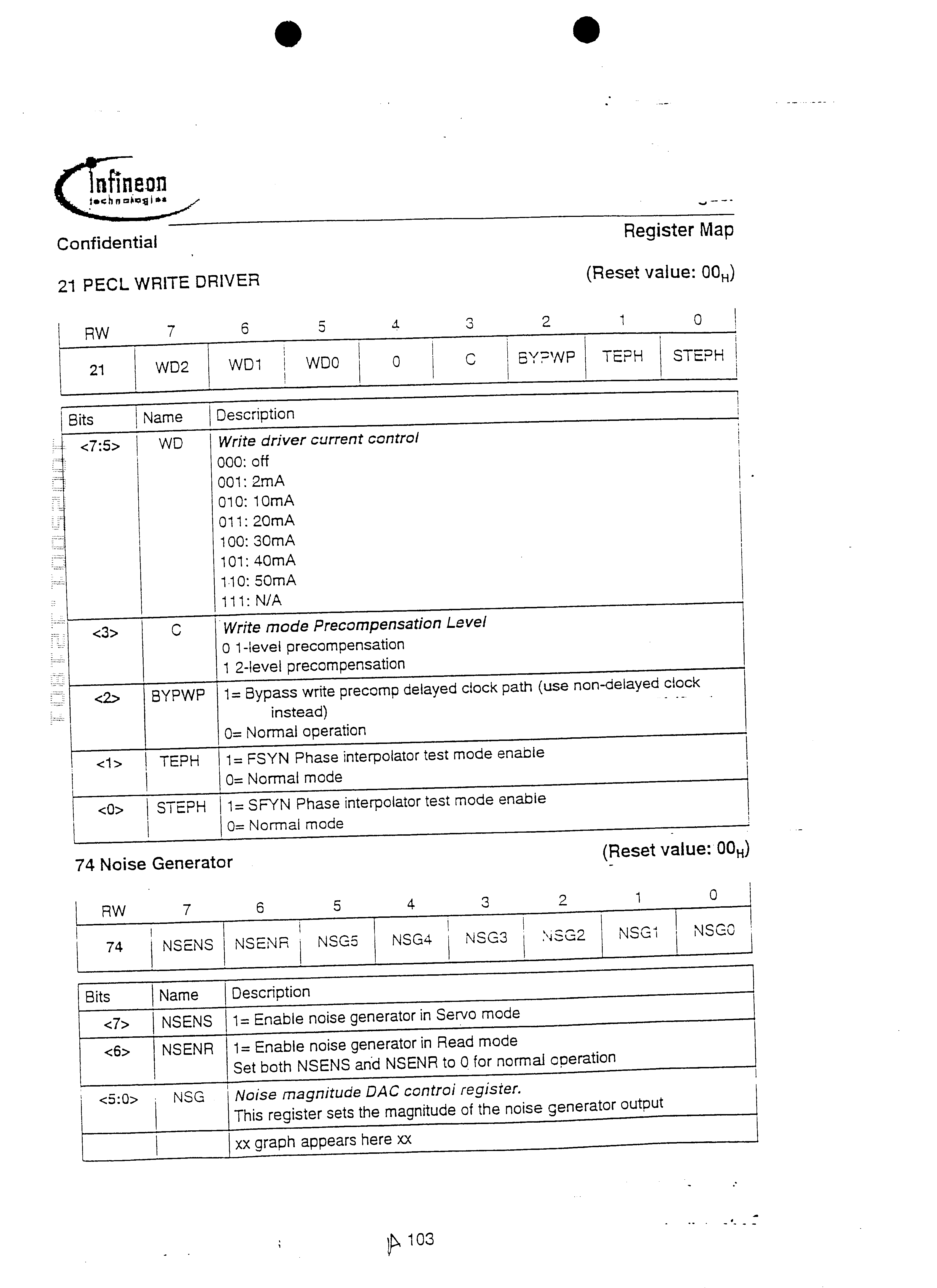
The precompensation circuit 126 is shown in FIG. 25 and shifts the time that a write data transition occurs. This attempts to compensate for the nonlinear bit shift effect of the write process. The circuit includes a plurality of phase select units 2502 a- 2502 d, a shift register 2504, select logic 2506, and a MUX register 2508. The circuit can select from 48 equidistant phases of write clock. The programmable range is 0-37.5% of the period of the write clock, with a delay step of 0.78125%. First order precompensation is selected by setting register 21<3> to 1. Decoding logic decides how much time shift to apply to a given transition according to the rules in Table 7:
TABLE 7
Write Precomp Settings
T(0) shift (% of bit
T(−2) T(−1) period Level
1st order precomp 21<3> = 1
X Tr 24<6:0> × .78125% 1
X None 0
2nd order precomp 21<3> = 0
Tr None 22<6:0> × .78125% 2
None Tr 24<6:0> × .78125%
Tr Tr
23<5:0> × .78125% 2
None None 0
“Tr” indicates the presence of a write transition
The PECL interface 127 is illustrated in FIG. 26. The PECL interface interfaces to a preamp 2600. Fast current-switch outputs are provided to transfer write data to the read/write preamp. The logic levels are shown in FIG. 27 and Table 8.
TABLE 8
PECL Interface Specifications
Parameter Min. Max.
PECL output high voltage 1.8 V VDDP
PECL output low voltage 1.4 V VDDP-0.4 V
Tr and Tf (10 to 90%) .25 ns
Servo Function
The path for Servo Mode is illustrated in FIG. 28. When in Servo mode the analog signal path of the VGA 106, filter 110, and ADC 112, share the same circuitry that is used by the channel in Read mode. The analog filter 110 has separate and programmable cutoff and boost values that are enabled when SGATE is asserted. The digital servo 128 includes a correlator 2801 which outputs to a peak detector 2804 and ABS Value unit 2806. The output of the ABS Value unit 2806 is provided to a Burst Accumulator 2808 which outputs a burst value to the interface 122. The peak detector 2804 provides outputs to a preamble detector 2802 and to AM detect logic 2810 and Gray Code logic 2812; the outputs of these logic units 2810, 2812 are also provided to the interface 122.
The digital servo block 128 uses an asynchronous clock (i.e. no phase or frequency coherence to servo data) that is programmed to a sample rate of 8×, 10×, or 12× multiples of the servo synchronization frequency. The clock is generated by a dedicated PLL servo synthesizer, which is programmed to achieve the desired oversample rate.
The correlator circuit 2801 is shown in greater detail in FIG. 29. The correlator 2801 is a simplified matched filter that is used to detect di-bits. This circuit suppresses DC shift, low frequency noise and second harmonic distortion such as amplitude asymmetry in MR heads. The correlator 2801 is a FIR filter producing an output of Xk+n−xk where n can be programmed to 4, 5 or 6 using MUX 2902 to match over-sample rates of 8×, 10× or 12× respectively. The correlator transfer function is illustrated in FIG. 30.
The preamble detect block 2802 enables address mark detection when a valid Servo preamble is detected. It contains the control logic that generates the signal, sample_AGC, which is an input to the AGC block 129/131. The preamble detect block 2802 is configured in several different modes, depending on which search mode is current. The search modes are explained in greater detail below.
Register R[*]1, is programmed with the number of consecutive di-bits that must be detected to qualify as detected preamble. Register Rli*]2, contains a bit to disable the preamble detector. Either a micro or a timer enables the preamble detector to begin the search, and the circuit waits for a peak to be detected. When a peak is found the circuit will look for the another peak to occur within a given window. The size of the window is based on the over-sample ratio. When peak is detected outside of the expected window, or if the peak isn't detected within the window at all, the detector will reset and start the process over. However when a valid peak is detected, a second counter is incremented. When this second counter is equal to the value programmed in register R[*]1, the preamble_detected signal is asserted. This signal remains active until an address mark has been detected, or until the search has been terminated.
The sample_AGC signal has three different modes of operation: it can be manually controlled with a register bit, it may be configured to auto sample after each successful preamble detection, or a normal mode that is used in oriented search mode where sample_AGC will be active after the “start search” bit is set.
The AGC block 129/131 receives the sampled value of “peak sample” from the peak detector and calculates a correction that is input to the VGA. The gain DAC in the AGC block is only updated when the signal, sample_AGC, from the preamble detect block is asserted. The AGC can also be preset prior to each servo sample by initializing the AGC_preset register R[*]3. Preset occurs on the next rising edge of SGATE. During initial searches when SGATE is always active, initializing the preset Register will generate an update of the gain DAC. If the preset register is loaded when SGATE is switching, the new value will update the GDAC on the next rising edge of SGATE.
The AGC block has a linear, and non-linear mode. Four gain bits control the gain as a function of the mode selected. Register R[*]4, an eight bit signed number is used to preset the AGC correction value. Register R[*]5 is programmed with the desired target AGC peak value, which is compared to the peak samples, with the difference being the AGC error. The AGC error is scaled as a function on the gain settings, then added to the previous AGC correction. The AGC correction is then formed from numerically integrated gain errors. The AGC correction input to the VGA is an eight bit unsigned number centered around 80 H. The AGC sample signal may be forced active by register control, when used for an initial search. Register R[*]6 is used to program the number of corrections to be made in normal and auto-sample modes. Examples of how the hardware and software may be used in different search modes are discussed below.
Unoriented Search Mode
Signaling for the unoriented search mode is shown in FIG. 31.
1. Get out of the latch.
2. Force SGATE active using the “timerset’ register in the controller.
3. Preset AGC gain to a high value, set AGC to non-linear mode.
4. The bit register R˜7*]l 0 in the channel comes up reset so that the preamble detect logic is enabled on power-up.
5. Set Force AGC bit, register R{*]l 1, for manual mode. This allows the AGC loop to run during the entire time that the servo gate is active. Due to the use of non-linear mode AGC, the loop should acquire relatively quickly over servo data and move to only moderately higher gain over non-servo data.
6. Set uP Search bit, register R[*]12. This will start the preamble detector. When the preamble is detected, the address mark detect logic will be enabled.
7. After the address mark has been detected, clear the uP_Search bit, register R[*]12. In this mode, the search will be controlled by the microprocessor by setting and clearing this bit.
8. Complete the normal AMET/GRAY CODE qualification code algorithm that is currently in use. In this mode the search is still controlled by the controller, using the uP_Search bit in the system.
After a number of address marks found, we may switch the enable_auto_sample bit, register R[*]l 3, to the Auto-sample mode setting, which clears the force-AGC bit. This will enable the logic that will generate a sample_AGC window after the preamble is detected for the number of di-bits programmed in the AGQ.sampleval register R[*]14. After the qualification is complete, switch to oriented search mode.
Unoriented Search (Auto Sample AGC) Oriented Search Mode
1. Set en_amsync bit in the channel and in the controller to enable the timer controlled searches. These are two separate bits with the same name that have the same function. This assumes that the timers have all been programmed in the controller.
2. Clear the register R[*]20< > bit and set the register R[*]21< > bits. Setting the register R[*]register R[*]21< > bit puts the sample AGC logic in the normal AGC mode. This enables sampleAGC for the number of di-bits programmed in the register R[*]22. This register may have to be reprogrammed if the number of sample di-bits is different than the number required in the auto-sample mode. In this mode, the sampleAGC window will start after the start search (spincomm) timer goes active.
Head Switch (option 1)
1. Switch heads. This occurs between servo bursts.
2. Preset AGC to high gain in the channel, non-linear AGC with high gain. The logic will remain in normal AGC mode.
3. Increase the AGQsample_val in the channel to allowing more time to acquire. (What would be the maximum required number of di-bits?)
4. Reprogram SGATE and spincomm timers to allow the use of more preamble. (Write to read recovery area.)
5. After first address mark, reprogram timers and AGCsample_val back to normal values. Set the AGC back to linear mode and normal gain.
Head Switch (option 2: worst case scenario)
1. Switch headsE
2. Force SGATE active using the timerset register in the controller.
3. Preset AGC to high gain, non-linear AGC. Set AGC in non-linear mode, same as unoriented search.
4. Set Force_AGC bit in channel. Controller timers will still be in oriented search mode, wider window.
5. Wait for AMDET to interrupt to the uP, then clear the Force_AGC bit in the channel. Normal AGC operation will continue from this point.
The peak detector 2804 (FIG. 28) derives a signal, peak_samples, that is used for the AGC. Other peak detector outputs are; peak found and threshold crossed. The input to the peak detector is sample and sample_minusl signals from the correlator 2801. The peak detector 2804 only detects positive peaks. The incoming samples are compared to a programmable threshold, and when either a positive or negative sample crosses the threshold, the threshold_crossed output will be set. This signal remains set until the peak is found. The peak is found using the following algorithm: Wait until threshold_crossed is true. Then wait until the current sample is less than the previous sample, sample minus 1, indicating that the peak has been reached. Next, there are two sample pairing conditions to be considered. If the sample_minusl is less than the sampieminus2, then the peak occurred at sample minus 2, or if the sample is less than the sample_minus 1, then the peak occurred at sample minus 1. When the peak sample is found, the peak_found signal is asserted, and at the threshold_crossed signal is cleared. The peak found signal will remain active for one sample clock period.
There is an input to the peak detector, sample AGC, which is output from the preamble detector 2802. When this signal is asserted, the value of each detected peak will be registered on the peak sample output, one sample clock after the peakjound signal is asserted. This is the value used by the AGC block to generate a gain correction.
The Address Mark Detect circuit 2810 (FIG. 28) is designed around a programmable address mark of nine bits. The address mark is defined by programming 9 bits composed of registers R[*] and R[*]. Table 7 illustrates the address mark format. In this example a written pattern of 8 zero's, followed by a di-bit is represented.
TABLE 9
Servo Address Mark Format
8 7 6 5 4 3 2 1 0
R[*]<0> R[*]<7> R[*]<6> R[*]<5> R[*]<4> R[*]<3> R[*]<2> R[*]<1> R[*]<0>
0 0 0 0 0 0 0 0 1
The address mark detector 2810 also contains a voting circuit that can be enabled to allow a finite number of errors to occur within the address mark. The number of allowed errors is programmed in register bits RE*]18. After a servo event, it is possible to poll register bits R[*11 9 to determine how many errors awere made in the previous servo event, as shown in Table 10:
TABLE 10
Servo Mark Detection Settings
Number of Actual
R[*] Allowed Errors R[*] Detected Errors
00 0 Bit 7 0 Errors
01 1 Bit 6 1 Error
10 2 Bit 5 2 Errors
11 N/A
FIG. 34 shows a 10 MHz servo waveform with the address mark and the correct polarity for the address mark dibit.
The Gray code detector 2812 has four functions: to detect the Gray code bits, to generate a Gray clock, to store the Gray code data in a shift register and to generate the grayendb signal. The gray decode block 2812 is clocked by a counter (graycnt) that increments on each falling edge of the sample count. This counter is held preset when AMDET is low and is reset at the end of each di-bit cell/window. The preset value can be programmed in the grayendval register Ril*], and is adjusted based on the oversample ratio. The reset value is determined based on the sample rate selected. Once the address mark is detected, the Gray code detector 2812 is enabled, and the timing of the detector is (becomes) relative to the peak of the address mark di-bit. The AMDET signal has a resolution of +1−1 half rate clock, which is 1/2 the oversample frequency.
The Gray data flip-flop is set any time that a peak is detected and is reset at the start of every di-bit window (when grayjrcnt=0). The Gray clock is generated 1/2 sample clock prior to the end of the cell. The Gray clock is used to shift the data into the Gray code shift register. It no address mark is detected, the shift register will contain the data from the last burst.
The grayendb signal determines how many Gray codes are to be shifted in. This value is programmable with the gray.endval register, which is compared to a counter that determines the number of gray clocks that have occurred.
EXAMPLE
Sample rate=12ט6 clocks per di-bit
Graypreset=2
Graycnt=0-5
Graycnt=0=reset gray data FF
Graycnt=5˜gray clock
The Reset AMDET timer runs off of the reference clock and the counter is reset with a synchronized AMDET signal. It can be programmed with a 12-bit value for the time the AMDET signal is reset. The rst_amb signal resets AMDET, and also resets or re-enables several other functions within the digital servo block.
Time desired in ns is R[*]30< >×TFREF Note: The resolution is +/˜1 TFREF due to the synchronization of the AMDET signal, which resets the counter.
The Demod block 2808 calculates the values for the A,B,C, and C position bursts. This function accumulates the magnitude of all of the samples in the accumulation window to measure the area of a burst. The strobe signal from the controller enables a counter (not shown) clocked by the sample clock. The counter is used as a 2-edge timer that opens a window to enable the accumulator. Two 6-bit registers control the timer, called start_accum and stop accum. When the window is open, the accumulator sums the absolute value of the output samples of the correlator. There are four separate adders, 2 pairs that are interleaved, one that sums the two samples and one that accumulates the output of the first adder. When the en_accum signal goes inactive, an additional adder sums the output of the two interleaved accumulators. There is additional clock delay that will have to be considered when centering the windows around the bursts. The peakjound and en_accum signals come out on a test pin and should be useful in centering the sample windows.
From the rising edge of the strobe signal, the en_accum signal goes active after the number of clocks programmed in register R[*]40. When programming the start register, one needs to account for the preload required by the correlator of half of a di-bit. The value programmed in the stop.accum register should allow the signal en_accum, to go inactive 2-3 clocks prior to the falling edge of strobe. This will allow time for the final addition and setup of the output latch. The accumulator is cleared 2 to 3 sample clocks after the falling edge of the strobe. The clear signal to the accumulator is deasserted 2 sample clocks later. This means that the strobe is deasserted a minimum of 5 sample clocks.
The Data Transfer block 122 controls the NRZIO bus during a servo burst. The servo controller is clocked by the negative edge of RCLK. When the servo address mark is detected, the NRZIO interface receives data from the servo. In this state, data is set to all zeros. The servo controller is controlled by a synchronized version of the strobe signal (synchronized to RCLK). The servo controller waits for the first transition (rising edge) of the strobe signal A_burst. On the next falling edge of RCLK after the rising edge of the strobe the NRZIO output is a sync byte, followed by the 3 bytes of Gray code, followed by all zeros again. The sync byte out will be the same sync byte that is used by the channel. All data will be clocked out on the falling edge of RCLK. On the falling edge of the first strobe, the channel will output a sync byte, followed by the two bytes of data. This will be repeated for the B,O and C. The data transfer after the D burst will have 1 additional byte that will be a status byte from the channel. Note that the inactive time between strobe pulses must be at least 1 RCLK cycle to ensure proper operation of the data transfer. RCLK is a divided down version of the read synthesizer and is “gapped” to account for the channel code rate. So for a 1 6/17 rate channel, RCLK has three spacings of 8T, followed by one spacing of 9T. The worst case RCLK spacing is: 1/(channel rate)*9 where the channel rate is 17/16*NRZ Pate.
Common Functions
Several functional blocks are shared by the read, write, and servo sections of the channel. These are the NRZ interface 122, the R/W PLL 138, the Servo PLL 140, and the serial interface 142.
The RAW interface 122 provides a read clock RCLK, receives a write clock WCLK, and reads and writes data on a byte wide NRZIO interface. NRZI read interface timing is shown in FIG. 35. NRZI write timing is shown in FIG. 36. While the figures show byte-wide data being clocked to and from the channel on the rising edge of the clock, the polarity of the RCLK and WCLK signals may be altered by programming registers 20<4> and 20<5>, so that data may be clocked on either edge. Interface timing rules are defined in Table 11:
TABLE 11
NRZIO Interface Timing.
Parameter Sim. Condition Min. Max. Units
RCLK, NRZIO rise/fail time Tr & 20-pF output load, 10-90% 3.7 Ns
tf
RCLK to NRZIO delay Tp Falling edge of RCLK to NRZ 3.5 ns
out
NRZIO setup time Tsu NRZ data valid to rising edge 3 Ns
of WCLK
NRZIO hold time tn Rising edge of WCLK to NRZ 2 Ns
data invalid
RCLK high Thr Period RCLK is high 4 5 15/16 bit
period
RCLK low time Tlr Period RCLK is low 4 6 15/16 bit
period
WCLK high time Thw Period WCLK is high 4 5 Bit period
WCLK low time Tlw Period WCLK is low 4 5 Bit period
RCLK and WCLK (8 + 9 + 8 + 9 + 8 + 9) 51 PLL clock edges
periodicity
Direct Write mode WCLK (8 + 8 + 8 + 8 + 8 + 8) = 48 PLL clock edges
periodicity
A one-period ambiguity exists in RCLK high and low times. This constraint is reflected in the clock times listed in Table 11.
The PLL synthesizer 134 uses a single phase locked loop 138 to synthesize Read mode and Write mode (R/W) clock signals. A second PLL 140 is used to synthesize Servo mode clock signals. Both PLL designs are identical, with the exception of a 16/15 frequency translation function that is added to the R/W PLL 138. The designs have been optimized for high bandwidth, fast lock-on operation and extremely low jitter output.
A block diagram of the RAW PLL synthesizer block 138 is shown in FIG. 37, and the specifications follow in Table 14. The PLL output frequency is determined by Equation 2:
R/W FREQ=NREF×(N−P/16)/(2×(M+1))   Eq. 2
The N and P values should be chosen such that:
700 MHz<=FREF×(N−P/8)<=1600 MHz
As shown, the synthesizer block 138 includes a phase detector 3702, a charge pump 3704, loop filter 3706, VCO 3708, frequency translation circuit 3710, divider 3712, and feedback divider 3714. The input FREF is an external reference input frequency, and N, P and M are integers. The output bit-rate frequency is programmed by loading the 91<5:0>, the 90<7:4> and the 90<2:0> registers.
The operation of the P/W PLL 138 is as follows: The VCO output frequency, Fvco, which is in the range of 800-1600 MHz, is divided by the fractional divider 3714 of factor (N−P/16), and then phase-compared to an input reference frequency FREF, by phase detector 3702. Use of the fractional divider 3714 allows the phase detector 3702 to sample the phase error at a high rate, providing faster lock-on times with lower VCO phase jitter. The PLL P/W clock output is obtained by dividing Fvco by 2(M+1) using digital divider 3812. The user sets the R/W clock frequency to be the same as the desired encoded bit-rate. When the PLL provides the Read mode clock, a 1 6/15 frequency translation circuit 3710 is automatically inserted in the clock path to increase the clock rate by 6.66% (the bit-rate is unchanged). This provides an oversampled clock for use by the interpolated timing recovery (ITR) circuitry 116 (FIG. 1).
A block diagram of the Servo PLL synthesizer block 140 is shown in FIG. 38, and the specifications follow in Table 12. The Servo PLL 140 is similar to the R/W PLL 138 in form and operation. A separate and complete set of registers are used to program the Servo PLL 140. The PLL output frequency is determined by Equation 3:
Servo FREQ=FREF×(Ns−Ps/16)/(Ms+1)
The Ns and Ps values should be chosen such that:
700 MHz<=FREF×(Ns−Ps/8)<=1600 MHz
As shown, the synthesizer block 140 includes a phase detector 3802, a charge pump 3804, loop filter 3806, VCO 3808, divider 3812, and feedback divider 3814. The Servo output frequency is programmed by loading; the 91<5:0>, 90<7:4> and 90<2:0> registers. When a non standard FREF frequency is employed then Equation 3 is used to find Ps M5, and Lp5 values, subject to constraints of Equation 3.
TABLE 12
Clock Synthesizer Specifications
Parameter Symbol Min Max Register(s) Notes
Reference Frequency FREF 20 MHz 80 MHz 98<7:4> in steps of 5 Mhz
VCO Frequency Fvco 800 MHz 1600 MHz
Write or servo clock 53.125 MHz 800 MHz
Settling Time 10 usec
Absolute jitter 15 psec 1 sigma
Register settings - Read Mode/Write Mode
N divide value N 12 48 N = 91<5:0>
P divide value P 0 15 P = 90<7:4>
M divide value M 0 7 M = 90<2:0>
Register settings - servo mode
Ns divide value Ns 12 48 Ns = 93<5:0>
Ps divide value PS 0 15 Ps = 92<7:4>
Ms divide value Ms 0 7 Ms = 92<2:0>
The serial interface 142 allows communication between the controller and the internal control registers of the device. Any given internal control register may be read-only (R), write-only (W) or both read and write (RW). The serial interface 142 communicates by three control pins, SDEN, SDATA and SCLK, by using the transfer protocol shown in FIG. 39 with port timing rules specified in Table 13.
TABLE 13
Serial Port Timing Specification
Parameter Min Max
t
d1 5 ns
t d2 5 ns
tnd 10 ns
The interface controller arbitrates the transfer and is always responsible for setting the direction of the transfer, for generating the address bits and for generating the clock. The transfer protocol is structured as an 18-bit word. The first bit is used to indicate a write-to or read-from the device. The next eight bits function as address bits, with the LSB sent first. A dummy “turn-around” bit is added in the middle of the bit stream to allow time for a direction change on the bust Eight data bits follow either to or from the device, depending on the direction of the transfer.
During a register write operation, SDEN is asserted and serial data on the S DATA pin is clocked to the device on the positive edge of SCLK. After the 18-bit sequence is complete, byte-wide data is transferred to the selected device control register on the negative edge of SDEN.
During a register read operation, the bus direction and the address are clocked into the device on the positive edge of SCLK. After the turn-around bit, the device assumes control of the S DATA line and places the contents of the requested register, LSB first, to SDATA on the falling edge of SCLK.
System Operation
Operation of the Read, Write, and Direct Write modes follows and, in particular, on exemplary timing relationships that are in effect when transitioning from one mode to another.
Read Mode Sequence
Exemplary read mode sector architecture is shown in FIG. 40. Shown are the RGATE waveform 4002, the Read Signal 4004, the MTP wave form 4005, and the NRZIO wave form 4007.
The Read Signal 4004 includes a preamble 4006, sync byte 4008, and user data 4010. The preamble 4006 is implemented as a series of 2T-spaced transitions, with T being the encoded bit period. The preamble readback pattern input to the ADC 112 is a sine wave of frequency 1/4T. In one implementation, the system has a preamble length of 96 bits, although shorter and longer preamble lengths may be used. If the preamble field 4006 is less than 80 bits, the timing and gain synchronization may become unreliable. The preamble field 4006 is a known reference pattern that is used to set up timing, gain and DC-restore loops. Because the preamble is a single frequency, it cannot be used as a referenceto adjust the self adaptive FIR equalizer.
A sector read operation begins with the assertion of RGATE 4002. The timing loop cycle occurs in three phases, dividing the preamble 4006 into distinct regions: zero-phase restart 4012, fast-acquire 4014, and data tracking 4016. During the first phase, zero-phase restart 4012, the initial phase of the timing loop is adjusted. The second phase, fast-acquire 4014, is primarily used for frequency acquisition. After the first and second phases, the timing loop phase-frequency is close to the target phase-frequency value and within the capture range of the third and final phase, data-tracking 4016. During tracking 4016, the timing loop response is adjusted to be slow responding, requiring many averaged data samples to generate significant clock timing adjustments. Tracking mode 4016 is used for accurate and jitter-free data clock regeneration when reading user data. The AGC loop (FIG. 9) operates throughout all three timing phases. However, the loop gain of the AGC is increased during the zero-phase restart and fast-acquire phases so that channel gain is close to the correct value before entering tracking mode. The AGC tracking phase adjusts the gain very slowly throughout the user data and requires an average of many samples to significantly change the gain setting.
Programmable counters (not shown) are used to define the time intervals for each phase of the acquire sequence 4014. Acquisition timing periods may be adjusted for preamble lengths up to 500 bits by programming the counter-timers described in FIG. 41. The range of values allowed for each counter is specified in Table 14.
TABLE 14
Counter Values
Delay Description Range Register Default
Tadp FIR self adapt Fixed
Tacq Timing and dc 0-127 nibbles 09<6:0>
fast acquire
Tagc AGC acquire 0-127 nibbles 0A<6:0>
A sector read operation begins with the assertion of RGATE 4002 (FIG. 40). The system cycles through the loop acquire sequence described above. After the sequence is completed, timing and gain control loops have converged and the tracking mode 4016 is entered. The device begins detecting data and searches for a unique sync-byte pattern 4008 in the bit-stream. The sync-byte 4008 is a special pattern used as a marker to indicate the start of user data. Once the sync-byte 4008 has been detected, an FFh byte is output on the NRZIO bus. Subsequent detected and decoded user data bytes continue as output for as long as RGATE 4002 is asserted.
Approximately 16 bytes of read data latency are associated with a read operation as shown in FIG. 40 and FIG. 42. As a consequence, when RGATE 4002 is de-asserted at the end of a sector 4203, 16 bytes of data are left to be transferred to the controller. This residual data can be transferred using one of two methods, as selected by register 04<0>. The first method is for the controller to assert RGATE 4002 after the physical end of sector data, until the entire sector has been transferred. This is adequate provided the end of sector gap 4206 is greater than 16 bytes.
Using the second method, RGATE 4002 is de-asserted at the end of the sector. The device internally extends RGATE 4002 to flush out the residual data that is in the data path. When reading consecutive sectors, the combined length of the sector gap, the preamble length, and the sync mark must be longer than the 15 byte read latency, and the controller must be able to accept NRZ data even after RGATE has been de-asserted.
Write Mode Sequences
Data may be transferred from the controller to the NRZIO interface 122 (FIG. 1), through the system to the write preamp by two basic methods, called Normal and Direct modes. Both methods have selectable options that modify how write data is processed.
Normal Write Mode
The timing of a Normal Write mode operation is shown in FIG. 43. Shown are a WGATE waveform 4300, an NRZIO waveform 4302, and a Write Data waveform 4304. A normal Write mode operation is initiated when WGATE 4300 is asserted. A series of 00h bytes 4303 (FIG. 43) are sent from the controller to the device on the NRZIO interface 122 (FIG. 1). The encoder 123 output is a series of 2T-spaced transitions that generate the preamble 4306. The preamble 4306 is continued for as long as 00h bytes are sent to the interface 122. When an FFh byte 4305 appears on the NRZIO interface 122, write logic output is a sync-byte 4308 in place of the FFh, followed by encoded user data 4307 lasting the duration of WGATE assertion. Write data is subsequently precompensated and transferred to the PECL output stage 127. In the implementation illustrated, the Write path latency is 9 bytes. Data may be clocked to the device on the NRZIO interface 122 on either the rising or falling edge of RCLK depending on the setting of register 20<4>1.
Direct Write Mode
The write sequence for a direct Write mode operation is shown in FIG. 44. Shown are a WGATE waveform 4400, an NRZIO waveform 4402, and a Write Data waveform 4404. In operation, in a manner analogous tothe normal Write mode, WGATE 4400 is asserted; however, the encoder and scrambler 123 are bypassed by setting register 20<1>=1 and the write precoder 124 is bypassed by setting register 20<1>=1. NRZIO data is serialized, precompensated and then transferred directly to the PECL output 127 without modification. The controller sends a sequence of 00h bytes, followed by one FFh byte 4403. This is followed by the continuation of user data 4405 for as long as WGATE is asserted; the FFh byte is not transferred. If a Read mode operation is desired after a Direct Write mode, the write data placed on the NRZIO interface 122 must contain the preamble, sync-byte, encoded data and any necessary ECC bytes.
System Timing
A system timing diagram is shown in FIG. 45. Timing rules are listed in Table 15:
TABLE 15
Timing Rules
Parameter Min Time Description
T
s/r 24 Read mode PLL Clocks Servo to read
T r/s 24 Read mode PLL Clocks Read to servo
T
s/w 24 Read mode PLL Clocks Servo to write
T w/s 24 Read mode PLL Clocks Write to servo
T
w/s 24 Read mode PLL Clocks Servo mode to write
mode/servo mode
T
s/w 24 Read mode PLL Clocks Write mode/servo mode
to idel mode
T
w/w 24 Read mode PLL Clocks Write mode to write mode
T
r/r 24 Read mode PLL Clocks Read mode to read mode
Ts/d 500 ns Suspend mode to doze
mode
T
d/l 100 us Doze mode to idle mode
T
i/s 24 Read mode PLL Clocks Idle mode to servo mode
T
s/l 24 Read mode PLL Clocks Servo mode to idle mode
T
r/i 24 Read mode PLL Clocks Read mode to idle mode
Write Mode to Idle Mode Recovery
The timing diagram of the recovery sequence appears in FIG. 45. In particular, shown are a WGATE waveform 4600, a HiZ waveform 4602, and a LoZ waveform 4604. When WGATE 4600 is asserted, the series switches 202, 208 (FIG. 2), which are connected between the VGA input pins and the VGA circuit, are set to an open or high impedance (HiZ) state. The high impedance state prevents write voltage transients from entering the VGA 106 (FIG. 1) and overloading the analog signal path. The HiZ condition is maintained for the duration of WGATE and is extended past the de-assertion of WGATE for a programmable length of time, Thr, set in a register. In addition, a shunt resistance 210 connected in parallel with the VGA inputs, is set to a low impedance value (LoZ) during WGATE. The LoZ period starts 50 ns before the end of HiZ and extends for a period of time, TLR, set in a register.
TABLE 16
Parameter Description Time/Resistance
Thr Time VGA input-open is active after 50 ns × R,[TBD]
WGATE
TIr Time VGA input-LoZ active after 50 ns × R,[TBD]
(Thr-50 ns)
Select 200, 400, 1K or 2K Ohms for R
shunt LoZ
Channel Quality Monitor (CQM)
The functions shown in FIGS. 47a and 47 b may be used to collect statistical data on the overall performance of the magnetic recording channel. The active measurement function is selected by the FUNSEL register, 70<2:0>, as defined by Table 17:
TABLE 17
Channel Quality FUnctions
FUNSEL register
70<2:0> Function
0000 MSE1, squared error of received sample minus
estimated sample (slicer)
0001 MSE2, squared error of received samples minus
known sample (known data mode)
0010 MSE3, squared error of selected parameter
0011 SAT, surface analysis testing
0100 Histogram 1, referenced to estimated samples (slicer)
0101 Histogram 2
0110 Histogram 3
0111 Error rate
1000 Di-bit extraction
The parameter to be measured is selected by the MONSEL register, 70<6:3>. Taken together, the values of the FUNSEL and MONSEL registers define a CQM test. The combination of function and parameter that are supported are shown by an “X” in Table 18:
TABLE 18
Quality Monitor Test Matrix
FUNSEL Register 70<2:0>
Test Register MSE MSE MSE HIST HIST HIST Di-
MONSEL 1 2 3 SAT 1 2 3 Error bit
70<6:3> 0000 0001 0010 0011 0100 0101 0110 0111 1000
0000 ITR Data X X X X X X
0001 Gain Error X X
0010 Timing Error X X
0011 DC Restore X X
0100 MR Asym. X X
Error
0101 FIR Adt. X X
Error
0110 Sector Errors X
1
0111 Sector Errors X
2
1000 VA bit error X
1001 Slicer error X
1010 ECC BER X
CQM measurements are controlled by a finite state machine (FSM) that manages the selected test. The FSM state diagram is described in FIG. 48, allowed state transitions are listed in Table 19 and state variables are specified in Table 18.
TABLE 19
CQM Measurement
Event Trigger
Trigger Interface sets 68<5> = 1. Enables and resets the state
machine.
Start (on sync0byte found if (68<4> = 1)) otherwise on
RGATE assertion
P Complete P count is complete setting 68<3> = 1
RGATE before RGATE ends before P setting 68<0> = 1, an error
p indicator
Span sectors RGATE ends before Q and sector span is enabled,
68<1> = 1
M Done On (RGATE if 68<1> = 0) otherwise on (Q count
complete which also sets 68<2> = 1)
TABLE 20
CQM Variables
REG
Variable Definition
68<7> Trigger and reset
68<4> Start on sync byte found enable
68<3> P and count indicator
68<2> Q end count indicator
68<1> Enable sector span
68<0> Error flag
69<7:0> P and count value-Specific WAIT time (16 bit units)
6A<7:0> 12 bit Q end count value-MEASURE sample (in multiples of
6B<3:0> 16 bits)
6B<7:4> 12 bit Q counter value-number of measurements accumulator
6C<7:0> (in multiples of 16 bits)
72<7:0> Top 16 bits of CQM 20 bit measurement accumulator
71<7:0> (measurement)
6D<5:0> TH, high threshold
6E<5:0> TL, low threshold
6F<7:0> TE, Error squared threshold
6D<7> Sector error type
Single sector operation is described in FIG. 49. The measurement sequence is initiated when register 68<5> is set to 1. This event resets the state indicators and the P,Q and M counters. The FSM advances to the WAIT state where it waits for an RGATE assertion or a sync-byte-found signal depending on 68<4>. When the selected condition occurs, the FSM advances to the PAUSE state where a delay timer, F, counts P bits before transitioning to the MEASURE state. As a precautionary check, if the FSM is in the PAUSE state when RGATE is de-asserted, an error flag, register 68<0>, is set to 1 and the FSM returns to Idle mode.
While in the MEASURE state, data collection is enabled and parametric test data is accumulated in a 20-bit-wide register, called the M accumulator. Only the top 16 bits of the register are accessible through the serial port. An overflow condition is indicated by all the bits in the register being set to 1. A unit counter, or C counter, is enabled to keep track of the number of measurements processed. The Q counter and the M accumulator are active until the end count, in registers 6A<7:0> and 60<7:0>, is reached or RGATE is de-asserted Normally, measurement data accumulates until the end of sector, signalled by the end of RGATE. However, if 68<1>=1, data will accumulate until the end count of the Q counter, 6A<7:0> and 60<7:0>. The FSM returns to Idle mode, and the measurement value, contained in the M accumulator, and the number of measurements made contained in the C counter, may be retrieved through the serial interface.
Multiple sector operation is described in FIG. 50. If 68<1>=1 and if the end count is not attained when RGATE is deasserted, the FSM returns to the WAIT state and will continue to collect more data on the next sector or sectors. When the Q counter end count is reached, and the required number of measurements have been made, the FSM sets indicator 68<1> to “1”, and returns to the Idle mode state. With this method, the measurement may span multiple sectors.
Mean Squared Error
MSE1, MSE2 and MSE3 tests measure squared error. It is left to the user to calculate the real mean squared error by dividing the measured squared error by the number of measurements made, the value that is accumulated in the M counter.
For the MSE1 test, the error is calculated as the difference of the received sample output from the ITR and the estimated noiseless sample value. In the MSE2 test, the error is calculated as the difference in the received sample output from the ITR and a calculated sample derived from an onboard linear feedback shift register (LFSR). The MSE 3 test is used to measure the standard deviation of loop error signals.
Error Rate Tests
The M counter can be used to accumulate errors by using an number of different measures. When an error rate measurement is selected, the C counter increments on sectors read, i.e. on RGATE deassertion. After Q sectors have been tested, the state machine transitions to the Idle mode state. Assuming 512 byte sectors, 268 million bits may be tested before the counter overflows. This allows measuring error rates to 1 errors per bit.
Sector Error Rate (Zero-Pattern Method)
An all 00h byte data pattern is sent to the scrambler and encoder during Write mode. The 00h byte pattern is scrambled before being encoded and written to the disk. Upon readback, the detector, decoder and descrambler invert the process to reconstruct the 00h byte pattern. Errors are detected by the occurrence of non-O0˜ bytes. The error accumulator counts sector errors using two different criteria:
A sector with 1 or more bytes in error, counted as 1 sector in error, 6D.zz7>=0.
A sector with 5 or more bytes in error, counted as 1 sector in error, 6D 7>=1.
Statistically, for channel error rates less than 10˜ errors/bit, most sectors in error will contain only a single error event. However, that one error event may corrupt several bytes. When a single error event causes mis-synchronization, hundreds of bytes in error may be generated. Measure (1) will count either outcome as one error. Measure (2) will count only sectors with long bursts of errors, which are probably not EGG correctable. In order to test large numbers of bits, the OCM state machine parameter should be set to span multiple sectors.
Slicer Bit Error Rate
The output of the slicer circuit is compared to known data generated by a linear feedback shift register. For correct comparisons sector data must be written using the known-dataJ Write mode. Bit-wise miscompares are accumulated in the M counter. In order to test large numbers of bits, the CQM state machine parameter should be set to span multiple 71 sectors.
Viterbi (VA) Bit Error Rate
The output of the Viterbi detector is compared to known data generated by a linear feedback shift register. For correct comparisons sector data must be written using theknown-data Write mode. Bit-wise miscompares are accumulated in the M counter. In order to test large numbers of bits, the 0CM state machine parameter should be set to span multiple sectors.
Bit Error Rate with ECC
Sector data is written using the “zero pattern’ method as outlined in the sector error rate test. Byte output from the decoder is de-interleaved into four byte interleave sequences. One of the four interleave sequences is selected to be byte-wise compared to a zero byte. Byte miscompares are accumulated in the M counter. In order to test large numbers of bits, the 0CM state machine parameter should be set to span multiple sectors.
Di-bit Measurement
The di-bit extraction test deconvolves a pseudo-random binary readback sequence that has been written previously to a sector as data. The measurement evaluates one sector to determine one value of the di-bit function. Subsequent values are obtained by shifting the phase of the pseudo-random binary sequence (PRBS) that is used to generate known-data in the deconvolution equation. Data must be written using known-data Write mode. That is, 20<3> bit set to 1. When a normal Write cycle is executed, the device output is a repeating PRES data pattern that takes the place of normal encoded write data. ˜Write data input to the NRZIO interface from the controller is ignored. The synchronization field and sync-byte are output just as in a normal write, although a repeating PRBS is substituted for data.
On readback, the 127 bit PRBS is derived from a linear feedback shift register (LFSR) that performs the polynomial recursion, xn+8=(Xri 7+Xn+3+1)mod2· In this extraction algorithm, the phase of the PRBS determines the time variable of the extracted di-bit function. In order to obtain all 127 values of the extracted di-bit the phase of the PRBS is incremented by changing the starting value, the seed of the LFSR contained in 73<6:0>.
For the most accurate result, measurement data should be accumulated over multiples of 127 amplitude (ITR) samples. Since the C counter increments in multiples of 16 bits a recommended ending value for Q is 127, which is 16×127=2032 bits
SNR Margining Tests
Three different methods for SNR margin testing are supported in the SOA8700 device; additive white noise, off-track interference emulation and noise multiplication.
Additive White Noise Test
A white noise generator circuit can be used to add noise to the readback signal at the input of the CTF, output of the VGA. This effectively lowers channel SNR and increases bit error rate. When enough noise is added so that the error rate is between 10−6 to 10−7 (errors/bit) the error rate becomes a sensitive indicator of the effect of channel parameter settings. Pre-comp, head current, equalizer settings, etc. may then be more easily adjusted to find optimal settings. Injected noise is “white”, while preamp noise may be “colored”, and as a result the channel parameter settings found using this method may be only close to optimal. Because injected noise is added after the VGA, the effective SNR obtained will be relatively independent of the signal level input of the VGA, and will be repeatable to the extent that the CTF and FIR transfer functions are constant. The amplitude of the injected noise, which has a 300 MHz noise bandwidth is varied by register R,[TBD]. This can produce effective SNR's of 15 dB to 25 dB. SNR herein is defined as the isolated pulse peak voltage divided by RMS noise voltage.
Off-Track Interference Emulator
The input to the Viterbi detector prefilter can be artificially corrupted by adding a scaled output from a linear feedback shift register (LFSR). The amplitude of the LFSR can be varied by register 75<7:0>. The frequency content of the LFSR signal is designed to match the spectrum of off-track interference experienced by the channel during off-track stress testing (OTO).
Noise Multiplier Test
This test assumes known data, so a known-data write must be used to set up test data sectors. The known-data pattern used, a repeating PRBS, is modified to satisfy the parity constraint of the Viterbi detector by setting register 73<7> to 1.
The error signal at the input to the Viterbi detector prefilter is measured by comparing input amplitude samples to the known-data pattern. The derived error signal is multiplied by a scaling factor and then added back to the known signal. This uniformly multiplies all noises and distortions by the scaling factor, creating a uniform degradation of the effective detector SNR. The amplitude of the noise multiplication error is adjusted by register 75<7:0>.
Arbitrary Waveform Injection
The ViewDac circuit 5100 (FIG. 52) can be used to generate arbitrary waveforms that may be used to simulate analog input signals. These waveforms can be injected at various nodes in the analog signal path as illustrated in FIG. 51. A 32-word cyclic random access memory (RAM) 5102 is first loaded with waveform sample values via the serial interface. The clocked output samples are input to the viewdac (Vdac) 5100 where they are converted to analog values. As shown in FIG. 51, the output of the viewdac can be connected to various inputs in the analog signal path as selected by register AB<2:0>. The cyclic RAM 5102 is clocked from either the P/W PLL or Servo PLL depending on the setting of AB<3>. Normally, in this mode the input signal from the preamp, VIN(P,N) is disconnected from the VGA by setting AB<4> to 1.
The analog signal injection function may be used to simulate typical sinusoidal input waveforms that can be used with the CQM, to measure and calibrate the frequency transfer function of the VGA 106 and CTF 119.
View DAC
The system according to an implementation of the present invention allows real time viewing of digital signals in the analog domain by using a high speed, 7-bit View DAC. The View DAC 5100 is shown in FIG. 52, and operating modes are specified in Table 21 and Table 22. The view DAC circuit includes an input multiplexer 5202, clock multiplexer 5204, and View DAC 5206.
Register BO<2:0> controls the selection of internal signals which are routed to the View DAC. The selected data can then be brought off-chip at reduced or full speed depending upon the setting of B0<7:3>. The actual divisor will be the value of B0.<7:3>±1. For example, if the setting in this field is 000, then the data is divided by 1, and by 8 if the setting is 111.
TABLE 20
View DAC Input Select
B0<2:0> Description
000 Selects a value of 0 into the View DAC input
001 Selects the output from the ADC
010 Selects the output from the FIR
011 Selects the output from the ITR
100 Selects the output from the Viterbi
101 Selects the output from a 128-byte RAM
110 Selects the output from a user loaded serial port register
TABLE 22
View DAC Decimation
B0<7:3> Description
000 View DAC output is every clock period
001 View DAC output is every 2nd clock period
... ...
111 View DAC output is every 8th clock period
Analog Test Port
A differential analog test port may be used to monitor and inject analog signals along the signal path of the front end of the system. VGA input pins VIN_P and VIN_N are multiplexed to input ports along the signal path. ASIG_P and ASIGN pins are switched to the selected output along the signal path as shown in FIG. 53. Table 23 specifies the value of register AA<7:0> needed to connect a selected signal to the ASIG output pins.
TABLE 23
Analog Test Port
AA<7:0> Output Selected
00000000 No connect to Aout normal op.
00000001 Connects pins ASIG_P/ASIG_N to output test bus
00000010 VGA output
00000100 Asymmetry correction output
00001000 1st biquad output
00010000 CTF output
00100000 8 dB buffer output
01000000 S/H output
Multiplexed Test Pin (MTP)
A single MTP is used to connect to internal test signals. The function of the MTP is controlled by register BA<2:0>. Table 24 lists available signals
TABLE 24
Multiplexed Test Pin
BA<2:0> RGATE WGATE SERVO MTP Description
000 X X X NSYNC Not sync byte found
001 X X X WRITE_ERROR WRITE error
010 X X X GRAY_DATA Gray decode output
011 X X X PLLR_LOCKED Read PLL locked
100 X X X PLLS_LOCKED Servo PLL locked
101 X X X WRP_INVALID WRP pin valid/WRP error
110 X X X FIR_SATURATION FIR tap out of range
111 X 0 0 NSYNC Not sync byte found
111 0 1 X WRITE_ERROR WRITE error
111 0 0 1 GRAY_DATA GRAY decode output
The invention described in the above detailed description is not intended to be limited to the specific form set forth herein, but is intended to cover such alternatives, modifications and equivalents as can reasonably be included within the spirit and scope of the appended claims.
APPENDIX
A copy of the provisional application specification follows as Pages A0-1 through A0-3, and A1-A122.
Figure US06594094-20030715-P00001
Figure US06594094-20030715-P00002
Figure US06594094-20030715-P00003
Figure US06594094-20030715-P00004
Figure US06594094-20030715-P00005
Figure US06594094-20030715-P00006
Figure US06594094-20030715-P00007
Figure US06594094-20030715-P00008
Figure US06594094-20030715-P00009
Figure US06594094-20030715-P00010
Figure US06594094-20030715-P00011
Figure US06594094-20030715-P00012
Figure US06594094-20030715-P00013
Figure US06594094-20030715-P00014
Figure US06594094-20030715-P00015
Figure US06594094-20030715-P00016
Figure US06594094-20030715-P00017
Figure US06594094-20030715-P00018
Figure US06594094-20030715-P00019
Figure US06594094-20030715-P00020
Figure US06594094-20030715-P00021
Figure US06594094-20030715-P00022
Figure US06594094-20030715-P00023
Figure US06594094-20030715-P00024
Figure US06594094-20030715-P00025
Figure US06594094-20030715-P00026
Figure US06594094-20030715-P00027
Figure US06594094-20030715-P00028
Figure US06594094-20030715-P00029
Figure US06594094-20030715-P00030
Figure US06594094-20030715-P00031
Figure US06594094-20030715-P00032
Figure US06594094-20030715-P00033
Figure US06594094-20030715-P00034
Figure US06594094-20030715-P00035
Figure US06594094-20030715-P00036
Figure US06594094-20030715-P00037
Figure US06594094-20030715-P00038
Figure US06594094-20030715-P00039
Figure US06594094-20030715-P00040
Figure US06594094-20030715-P00041
Figure US06594094-20030715-P00042
Figure US06594094-20030715-P00043
Figure US06594094-20030715-P00044
Figure US06594094-20030715-P00045
Figure US06594094-20030715-P00046
Figure US06594094-20030715-P00047
Figure US06594094-20030715-P00048
Figure US06594094-20030715-P00049
Figure US06594094-20030715-P00050
Figure US06594094-20030715-P00051
Figure US06594094-20030715-P00052
Figure US06594094-20030715-P00053
Figure US06594094-20030715-P00054
Figure US06594094-20030715-P00055
Figure US06594094-20030715-P00056
Figure US06594094-20030715-P00057
Figure US06594094-20030715-P00058
Figure US06594094-20030715-P00059
Figure US06594094-20030715-P00060
Figure US06594094-20030715-P00061
Figure US06594094-20030715-P00062
Figure US06594094-20030715-P00063
Figure US06594094-20030715-P00064
Figure US06594094-20030715-P00065
Figure US06594094-20030715-P00066
Figure US06594094-20030715-P00067
Figure US06594094-20030715-P00068
Figure US06594094-20030715-P00069
Figure US06594094-20030715-P00070
Figure US06594094-20030715-P00071
Figure US06594094-20030715-P00072
Figure US06594094-20030715-P00073
Figure US06594094-20030715-P00074
Figure US06594094-20030715-P00075
Figure US06594094-20030715-P00076
Figure US06594094-20030715-P00077
Figure US06594094-20030715-P00078
Figure US06594094-20030715-P00079
Figure US06594094-20030715-P00080
Figure US06594094-20030715-P00081
Figure US06594094-20030715-P00082
Figure US06594094-20030715-P00083
Figure US06594094-20030715-P00084
Figure US06594094-20030715-P00085
Figure US06594094-20030715-P00086
Figure US06594094-20030715-P00087
Figure US06594094-20030715-P00088
Figure US06594094-20030715-P00089
Figure US06594094-20030715-P00090
Figure US06594094-20030715-P00091
Figure US06594094-20030715-P00092
Figure US06594094-20030715-P00093
Figure US06594094-20030715-P00094
Figure US06594094-20030715-P00095
Figure US06594094-20030715-P00096
Figure US06594094-20030715-P00097
Figure US06594094-20030715-P00098
Figure US06594094-20030715-P00099
Figure US06594094-20030715-P00100
Figure US06594094-20030715-P00101
Figure US06594094-20030715-P00102
Figure US06594094-20030715-P00103
Figure US06594094-20030715-P00104
Figure US06594094-20030715-P00105
Figure US06594094-20030715-P00106
Figure US06594094-20030715-P00107
Figure US06594094-20030715-P00108
Figure US06594094-20030715-P00109
Figure US06594094-20030715-P00110
Figure US06594094-20030715-P00111
Figure US06594094-20030715-P00112
Figure US06594094-20030715-P00113
Figure US06594094-20030715-P00114
Figure US06594094-20030715-P00115
Figure US06594094-20030715-P00116
Figure US06594094-20030715-P00117
Figure US06594094-20030715-P00118
Figure US06594094-20030715-P00119
Figure US06594094-20030715-P00120
Figure US06594094-20030715-P00121
Figure US06594094-20030715-P00122
Figure US06594094-20030715-P00123
Figure US06594094-20030715-P00124
Figure US06594094-20030715-P00125

Claims (17)

We claim:
1. A read/write channel circuit to communicate with a magnetic head, the read/write channel circuit comprising:
a mode controller to select one of a plurality of operating modes for the read/write channel circuit, the plurality of operating modes including a read mode, a write mode, and a servo mode;
a read path through which a read signal from the magnetic head passes when the mode controller is in the read mode in order to read data in the read signal, the read path including:
a thermal asperity compensation unit to reduce distortions in the read signal caused by thermal asperity;
a variable gain amplifier to adjust an amplitude of the read signal;
an asymmetry control unit to compensate for the distortions in the read signal caused by a non-linear transfer function of the magnetic head;
a continuous time filter to attenuate high frequency noise in the read signal;
a programmable finite impulse response filter configured to equalize the read signal for data sequence detection when the mode controller is in the read mode;
an interpolated timing recovery unit to synchronize the read signal by resampling the read signal for data sequence detection;
a sync byte detector to detect sync marks in the read signal;
a Viterbi detector to detect data sequences in the read signal using the detected sync marks; and
a decoder to decode the detected data sequences;
a write path through which a signal carrying write data to the magnetic head passes when the mode controller is in the write mode in order to record the write data, the write path including:
an encoder to encode the write data; and
an output driver to provide a write current pattern for the magnetic head from the encoded write data; and
a servo path through which a servo signal from the magnetic head passes when the mode controller is in the servo mode in order to find address marks in the servo signal, the servo path including:
said variable gain amplifier to adjust an amplitude of the servo signal;
said continuous time filter to attenuate high frequency noise in the servo signal;
said programmable finite impulse response filter configured to equalize the servo signal for address mark detection when the mode controller is in the servo mode; and
a servo block to detect address marks in the equalized servo signal.
2. A read/write channel in accordance with claim 1, said read path being controlled by:
an automatic gain control loop to normnalize the amplitude of the read signal for data sequence detection by varying gain of the variable gain amplifier, and
a DC restore loop to nullify DC offset of the read signal before data sequence detection.
3. A read/write channel in accordance with claim 1, said encoder in the write path including a scrambler to break up repetitive sequences in the write data.
4. A read/write channel in accordance with claim 1, said output driver in the write path including a serializer to convert the write data from parallel to serial format, and a precoder to convert the serialized write data to a write current pattern.
5. A read/write channel in accordance with claim 4, said output driver in the write path including a precompensation unit to compensate for non-linear effects of a writing process in the magnetic head.
6. A read/write channel in accordance with claim 1, said servo block in the servo path including a correlator to detect di-bits in the equalized servo signal, and a servo preamble detector to enable address mark detection by detecting servo preambles in the equalized servo signal.
7. A read/write channel in accordance with claim 6, wherein the servo block in the servo path includes a peak detector to detect peaks in the servo signal, the detected peaks being used by the servo preamble detector to detect the servo preambles.
8. A read/write channel in accordance with claim 1, wherein the programmable finite impulse filter is configured to equalize the read signal to an extended partial response maximum likelihood waveform when the mode controller is in the read mode.
9. A read/write channel in accordance with claim 1, wherein the decoder in the read path includes a de-scrambler to unscramble scrambled data in the detected data sequences.
10. A read/write channel in accordance with claim 1, wherein the read path includes a read/write interface to transmit the decoded detected data sequence.
11. A read/write channel in accordance with claim 10, wherein the write path includes the read/write interface to receive the write data.
12. A read/write channel in accordance with claim 1, wherein the mode controller is configured to bypass the encoder in the write path when the mode controller is in a direct write mode.
13. A read/write channel in accordance with claim 1, wherein the write path includes a positive emitter coupled logic interface to transmit the write current pattern.
14. A read/write channel circuit to communicate with a magnetic head, the read/write channel circuit comprising:
a mode controller to select one of a plurality of operating modes for the read/write channel circuit, the plurality of operating modes including a read mode, a write mode, and a servo mode;
a read path through which a read signal from the magnetic head passes when the mode controller is in the read mode in order to read data in the read signal, the read path including:
a programmable compensation filter configured to filter the read signal for data sequence detection when the mode controller is in the read mode;
a detector to detect data sequences in the filtered read signal; and
a decoder to decode the detected data sequences;
a write path through which a signal carrying write data to the magnetic head passes when the mode controller is in the write mode in order to record the write data, the write path including:
an encoder to encode the write data; and
an output driver to provide write current pattern for the magnetic head from the encoded write data; and
a servo path through which a servo signal from the magnetic head passes when the mode controller is in the servo mode in order to detect address marks in the servo signal, the servo path including:
the programmable compensation filter configured to filter the servo signal for address mark detection when the mode controller is in the servo mode; and
a servo block to detect address marks in the filtered read signal.
15. A read/write channel in accordance with claim 14, wherein the programmable compensation filter includes:
a compensation unit to compensate for distortions in a signal from the magnetic head; and
a programmable filter unit to equalize the signal from the magnetic head to a target waveform.
16. A read/write channel in accordance with claim 15, wherein the compensation unit is configured to compensate for distortions caused by thermal asperity, non-linear transfer function of the magnetic head, and high frequency noise.
17. A read/write channel in accordance with claim 15, wherein the programmable filter unit includes:
an analog-to-digital converter to digitize the signal from the magnetic head;
a programmable finite impulse filter to alter the waveform of the signal from the magnetic head; and
a timing recovery unit to synchronize the signal from the magnetic head.
US10/025,001 2000-04-05 2001-12-18 Read/write channel Expired - Lifetime US6594094B2 (en)

Priority Applications (1)

Application Number Priority Date Filing Date Title
US10/025,001 US6594094B2 (en) 2000-04-05 2001-12-18 Read/write channel

Applications Claiming Priority (3)

Application Number Priority Date Filing Date Title
US19495400P 2000-04-05 2000-04-05
US82663301A 2001-04-05 2001-04-05
US10/025,001 US6594094B2 (en) 2000-04-05 2001-12-18 Read/write channel

Related Parent Applications (1)

Application Number Title Priority Date Filing Date
US82663301A Continuation 2000-04-05 2001-04-05

Publications (2)

Publication Number Publication Date
US20020154430A1 US20020154430A1 (en) 2002-10-24
US6594094B2 true US6594094B2 (en) 2003-07-15

Family

ID=22719503

Family Applications (1)

Application Number Title Priority Date Filing Date
US10/025,001 Expired - Lifetime US6594094B2 (en) 2000-04-05 2001-12-18 Read/write channel

Country Status (2)

Country Link
US (1) US6594094B2 (en)
WO (1) WO2001080238A1 (en)

Cited By (46)

* Cited by examiner, † Cited by third party
Publication number Priority date Publication date Assignee Title
US20020060869A1 (en) * 2000-10-23 2002-05-23 Hitachi, Ltd Apparatus, signal-processing circuit and device for magnetic recording system
US20030206358A1 (en) * 2002-05-03 2003-11-06 Loh David Kok Leong Head instability detection for a data storage device
US20030215045A1 (en) * 2002-05-20 2003-11-20 Fujitsu Limited Self-adjustment device in PLL frequency synthesizer and method thereof
US20030223522A1 (en) * 2002-03-22 2003-12-04 Masanobu Fukushima Bit synchronizing circuit
US20040165303A1 (en) * 2003-02-25 2004-08-26 Wu Dethau Adjustment of pole frequency and boost settings of a filter in a channel
US20040179287A1 (en) * 2003-03-13 2004-09-16 Fujitsu Limited Method of and apparatus for recording/reading information, circuit for recording/reading signal
US20050078394A1 (en) * 2003-10-10 2005-04-14 Hitachi Global Technologies Netherlands B.V. Apparatus for providing data dependent detection in a data read channel
US20050122877A1 (en) * 2003-12-05 2005-06-09 Canon Kabushiki Kaisha Information reproduction apparatus and method using maximum likelihood decoding
US20050243959A1 (en) * 2004-04-30 2005-11-03 Ashley Jonathan J Method and apparatus for synchronization mark detection with DC compensation
US20050265117A1 (en) * 2000-08-18 2005-12-01 Rambus Inc. Apparatus and method for generating clock signals
US20060061496A1 (en) * 2004-09-20 2006-03-23 Stein Anatoli B Self-adjusting PRML receiver
US20060176982A1 (en) * 2005-02-09 2006-08-10 David Berman Apparatus, system, and method for asymmetric maximum likelihood detection
US20060181934A1 (en) * 2005-01-19 2006-08-17 Saifun Semiconductors, Ltd. Methods for preventing fixed pattern programming
US20070280478A1 (en) * 2006-06-01 2007-12-06 Dell Products L.P. Data security system and method for high bandwidth bus
US7333290B1 (en) 2006-08-03 2008-02-19 Western Digital Technologies, Inc. Magnetic disk in a disk drive and method having improved null servo burst phasing
US20080130776A1 (en) * 2006-12-04 2008-06-05 Samsung Electronics Co., Ltd. Trellis encoder and trellis encoding device having the same
US20080144454A1 (en) * 2006-12-18 2008-06-19 Kraig Bottemiller Data storage device with data recovery process using fixed phase clocking for analog-to-digital conversion
US20080180825A1 (en) * 2007-01-31 2008-07-31 Seagate Technology Llc Detection of servo data for a servo system
US20090201602A1 (en) * 2008-02-08 2009-08-13 Aravind Raghunathan Long-term asymmetry tracking in magnetic recording devices
US7583459B1 (en) 2004-11-18 2009-09-01 Marvell International Ltd. Method and apparatus for write precompensation in a magnetic recording system
US20100127907A1 (en) * 2008-11-21 2010-05-27 Texas Instruments Incorporated Readback registers
US20100316108A1 (en) * 2009-06-15 2010-12-16 Novatek Microelectronics Corp. Device and method of data recovery
US8018670B1 (en) * 2008-10-28 2011-09-13 Marvell International Ltd. Evaluation apparatus
US8159768B1 (en) * 2008-06-25 2012-04-17 Western Digital Technologies, Inc. Detecting a servo address mark (SAM) in a servo field sync-up operation
US8164845B1 (en) 2007-08-08 2012-04-24 Marvell International Ltd. Method and apparatus for asymmetry correction in magnetic recording channels
US8201066B1 (en) 2008-03-28 2012-06-12 Western Digital Technologies, Inc. Disk drive comprising a trellis detector having a read signal whitener in the ACS circuit
US8339722B1 (en) * 2008-11-17 2012-12-25 Marvell International Ltd. Methods of demodulating a servo positon error signal on patterned media
US8503242B2 (en) 2011-04-14 2013-08-06 Micron Technology, Inc. Methods and devices for determining sensing voltages
US8810948B2 (en) 2012-12-20 2014-08-19 Lsi Corporation Over-sampled signal equalizer
US8810949B2 (en) 2012-12-21 2014-08-19 Lsi Corporation Equalization combining outputs of multiple component filters
US20150029608A1 (en) * 2013-07-25 2015-01-29 Lsi Corporation Array-Reader Based Magnetic Recording Systems With Frequency Division Multiplexing
US8947812B1 (en) 2014-03-27 2015-02-03 Western Digital Technologies, Inc. Data storage device comprising equalizer filter and inter-track interference filter
US9183877B1 (en) 2015-03-20 2015-11-10 Western Digital Technologies, Inc. Data storage device comprising two-dimensional data dependent noise whitening filters for two-dimensional recording
US9819456B1 (en) 2016-10-17 2017-11-14 Seagate Technology Llc Preamble detection and frequency offset determination
US9928854B1 (en) 2017-05-03 2018-03-27 Seagate Technology Llc MISO equalization with ADC averaging
US9954537B1 (en) 2016-12-23 2018-04-24 Seagate Technology Llc Wide frequency range clock generation with phase interpolation
US9979573B1 (en) 2016-12-23 2018-05-22 Seagate Technology Llc Position error signal burst demodulation
US9998136B1 (en) 2017-02-17 2018-06-12 Seagate Technology Llc Loop consistency using multiple channel estimates
US10084553B1 (en) 2016-12-22 2018-09-25 Seagate Technology Llc Iterative recovery from baseline or timing disturbances
US10152457B1 (en) 2016-10-25 2018-12-11 Seagate Technology Llc Target parameter adaptation
US20180365100A1 (en) * 2014-05-16 2018-12-20 International Business Machines Corporation Detecting single event upsets and stuck-at faults in ram-based data path controllers
US10164760B1 (en) 2016-10-18 2018-12-25 Seagate Technology Llc Timing excursion recovery
US10277718B1 (en) 2016-11-22 2019-04-30 Seagate Technology Llc Preamble defect detection and mitigation
US10382166B1 (en) 2017-02-22 2019-08-13 Seagate Technology Llc Constrained receiver parameter optimization
US10504553B1 (en) * 2019-03-20 2019-12-10 Western Digital Technologies, Inc. Data storage device transmitting delta servo control value over serial interface
US11716097B2 (en) 2021-12-29 2023-08-01 Western Digital Technologies, Inc. Signal correction using soft information in a data channel

Families Citing this family (28)

* Cited by examiner, † Cited by third party
Publication number Priority date Publication date Assignee Title
US6771442B2 (en) 2001-06-29 2004-08-03 Infineon Technologies Ag Off-track interference emulator
US6731443B2 (en) 2001-06-29 2004-05-04 Infineon Technologies Ag Total error multiplier for optimizing read/write channel
US6862223B1 (en) * 2002-07-05 2005-03-01 Aplus Flash Technology, Inc. Monolithic, combo nonvolatile memory allowing byte, page and block write with no disturb and divided-well in the cell array using a unified cell structure and technology with a new scheme of decoder and layout
US7137056B2 (en) * 2002-09-25 2006-11-14 Infineon Technologies North America Corp. Low error propagation rate 32/34 trellis code
EP1563500B1 (en) * 2002-11-22 2017-04-26 Marvell International, Ltd. An efficient analog front end for a read/write channel of a hard disk drive running from a highly regulated power supply
US6995938B2 (en) * 2004-05-06 2006-02-07 Hitachi Global Storage Technologies Netherlands B.V. Data recording system with servo pattern having pseudo-noise sequences
US6967808B1 (en) * 2004-05-13 2005-11-22 Hitachi Global Storage Technologies Netherlands B.V. Data recording system with servo pattern having pseudo-random binary sequences
US7079342B1 (en) * 2004-07-26 2006-07-18 Marvell International Ltd. Method and apparatus for asymmetry correction in magnetic recording channels
US7360147B2 (en) * 2005-05-18 2008-04-15 Seagate Technology Llc Second stage SOVA detector
US7395461B2 (en) 2005-05-18 2008-07-01 Seagate Technology Llc Low complexity pseudo-random interleaver
US7502982B2 (en) * 2005-05-18 2009-03-10 Seagate Technology Llc Iterative detector with ECC in channel domain
US7590165B2 (en) * 2005-07-08 2009-09-15 Industrial Technology Research Institute Sub-system based window placement and size decision mechanism and method thereof
US7522367B2 (en) * 2005-11-23 2009-04-21 International Business Machines Corporation Asynchronous read channel shaped toward generalized partial response characteristics
US7433142B2 (en) * 2006-02-01 2008-10-07 International Business Machines Corporation Using at least one servo channel to provide timing recovery and timing information to data channels
US7852965B2 (en) * 2007-07-30 2010-12-14 Quantum Corporation Windowed level detector for partial response channels
US8599973B2 (en) * 2008-04-30 2013-12-03 HGST Netherlands B.V. Detection of synchronization mark from output of matched filter upstream of Viterbi detector
JP2012520515A (en) 2009-03-10 2012-09-06 アイエムエス ソフトウェア サービシズ リミテッド Address intelligence system and method
EP2405577B1 (en) * 2010-07-06 2019-04-24 Cisco Technology, Inc. Phase detection method and circuit
US8625225B1 (en) 2011-08-29 2014-01-07 Western Digital Technologies, Inc. Disk drive compensating for asymmetry of magnetoresistive read element
US8665547B1 (en) 2012-08-17 2014-03-04 Western Digital Technologies, Inc. Disk drive multiplexing read signal and fly height signal to a transmission line
US8625217B1 (en) * 2012-09-27 2014-01-07 Lsi Corporation Branch metric computation and noise predictive calibration/adaptation for over-sampled Y samples
US9287859B2 (en) * 2013-04-19 2016-03-15 Micron Technology, Inc. Flexible input/output transceiver
TWI520495B (en) 2013-06-06 2016-02-01 財團法人工業技術研究院 Crystal-less clock generator and operation method thereof
US9281006B2 (en) * 2013-12-13 2016-03-08 Avago Technologies General Ip (Singapore) Pte. Ltd. Systems and methods for ATI characterization
US9111573B1 (en) * 2014-04-01 2015-08-18 Avago Technologies General Ip (Singapore) Pte. Ltd. Detection of end of preamble in read channel without interpolation
US10171127B2 (en) 2017-05-19 2019-01-01 Rohde & Schwarz Gmbh & Co. Kg Method, system and computer program for synchronizing pseudorandom binary sequence modules
US10606790B2 (en) 2018-04-16 2020-03-31 Intel Corporation Precoding mechanism in PCI-express
WO2020012550A1 (en) * 2018-07-10 2020-01-16 株式会社ソシオネクスト Phase synchronization circuit, transmission and reception circuit, and integrated circuit

Citations (6)

* Cited by examiner, † Cited by third party
Publication number Priority date Publication date Assignee Title
US5696639A (en) 1995-05-12 1997-12-09 Cirrus Logic, Inc. Sampled amplitude read channel employing interpolated timing recovery
US6031672A (en) * 1996-12-17 2000-02-29 International Business Machines Corporation Method and apparatus for servo data pattern detection
US6038091A (en) 1997-10-06 2000-03-14 Cirrus Logic, Inc. Magnetic disk drive read channel with digital thermal asperity detector
US6108152A (en) * 1996-10-01 2000-08-22 Seagate Technology, Inc. Redundant synchronization fields to improve disc drive read performance
WO2000063889A1 (en) 1999-04-16 2000-10-26 Infineon Technologies North America Corp. Asymmetry compensation for magnetoresistive sensor
US6219192B1 (en) * 1998-04-09 2001-04-17 Data Storage Institute Method and apparatus for the compensation of an additive signal in a data signal

Patent Citations (6)

* Cited by examiner, † Cited by third party
Publication number Priority date Publication date Assignee Title
US5696639A (en) 1995-05-12 1997-12-09 Cirrus Logic, Inc. Sampled amplitude read channel employing interpolated timing recovery
US6108152A (en) * 1996-10-01 2000-08-22 Seagate Technology, Inc. Redundant synchronization fields to improve disc drive read performance
US6031672A (en) * 1996-12-17 2000-02-29 International Business Machines Corporation Method and apparatus for servo data pattern detection
US6038091A (en) 1997-10-06 2000-03-14 Cirrus Logic, Inc. Magnetic disk drive read channel with digital thermal asperity detector
US6219192B1 (en) * 1998-04-09 2001-04-17 Data Storage Institute Method and apparatus for the compensation of an additive signal in a data signal
WO2000063889A1 (en) 1999-04-16 2000-10-26 Infineon Technologies North America Corp. Asymmetry compensation for magnetoresistive sensor

Non-Patent Citations (5)

* Cited by examiner, † Cited by third party
Title
Altekar et al., "A 700Mb/s BiCMOS Read Channel Integrated Circuit," 2001 IEEE International Solid-State Circuits Conference, XP-002177065, 3 pgs.
Bloodworth et al., "A 450-Mb/s Analog Front End for PRML Read Channels," IEEE Journal of Solid-State Circuits, XP-000931893, 1999, 34(11):1661-1675.
Chern et al., "SA 19.4: An EPRML Digital Read/Write Channel IC," IEEE International Solid-State Circuits Conference, XP-000753116, 1997, pp. 320-321, 479.
Chern et al., "SA 19.4: An EPRML Digital Read/Write Channel IC," IEEE International Solid-State Circuits Conference, XP-002177066, 1997, 8 pgs.
Fields et al., "SA 19.1: A 200Mb/s CMOS EPRML Channel with Integrated Servo Demodulator for Magnetic Hard Disks," IEEE International Solid-State Circuits Conference, XP-000999335, 1997, pp. 314-315, 477.

Cited By (86)

* Cited by examiner, † Cited by third party
Publication number Priority date Publication date Assignee Title
US20050265117A1 (en) * 2000-08-18 2005-12-01 Rambus Inc. Apparatus and method for generating clock signals
US7817367B2 (en) 2000-10-23 2010-10-19 Hitachi Global Storage Technologies Japan, Ltd. Apparatus, signal-processing circuit and device for magnetic recording system
US8144415B2 (en) 2000-10-23 2012-03-27 Hitachi Global Storage Technologies Japan, Ltd. Apparatus, signal-processing circuit and device for magnetic recording system
US7502189B2 (en) * 2000-10-23 2009-03-10 Hitachi Global Storage Technologies Japan, Ltd. Apparatus, signal-processing circuit and device for magnetic recording system
US20020060869A1 (en) * 2000-10-23 2002-05-23 Hitachi, Ltd Apparatus, signal-processing circuit and device for magnetic recording system
US20090021852A1 (en) * 2000-10-23 2009-01-22 Hitachi Global Storage Technologies Japan, Ltd. Apparatus, signal-processing circuit and device for magnetic recording system
US20110013306A1 (en) * 2000-10-23 2011-01-20 Hideki Sawaguchi Apparatus, signal-processing circuit and device for magnetic recording system
US20030223522A1 (en) * 2002-03-22 2003-12-04 Masanobu Fukushima Bit synchronizing circuit
US7251304B2 (en) * 2002-03-22 2007-07-31 Ricoh Company, Ltd. Bit synchronizing circuit configured to obviate errors from meta-stability
US20030206358A1 (en) * 2002-05-03 2003-11-06 Loh David Kok Leong Head instability detection for a data storage device
US20030215045A1 (en) * 2002-05-20 2003-11-20 Fujitsu Limited Self-adjustment device in PLL frequency synthesizer and method thereof
US6862152B2 (en) * 2003-02-25 2005-03-01 Seagate Technology Llc Adjustment of pole frequency and boost settings of a filter in a channel
US20040165303A1 (en) * 2003-02-25 2004-08-26 Wu Dethau Adjustment of pole frequency and boost settings of a filter in a channel
US7035029B2 (en) * 2003-03-13 2006-04-25 Fujitsu Limited Method of and apparatus for recording/reading information, circuit for recording/reading signal
US20040179287A1 (en) * 2003-03-13 2004-09-16 Fujitsu Limited Method of and apparatus for recording/reading information, circuit for recording/reading signal
US7173784B2 (en) * 2003-10-10 2007-02-06 Hitachi Global Storage Technologies Netherlands B.V. Apparatus for providing data dependent detection in a data read channel
US20050078394A1 (en) * 2003-10-10 2005-04-14 Hitachi Global Technologies Netherlands B.V. Apparatus for providing data dependent detection in a data read channel
US20050122877A1 (en) * 2003-12-05 2005-06-09 Canon Kabushiki Kaisha Information reproduction apparatus and method using maximum likelihood decoding
US7441177B2 (en) * 2003-12-05 2008-10-21 Canon Kabushiki Kaisha Information reproduction apparatus and method using maximum likelihood decoding
US7561649B2 (en) 2004-04-30 2009-07-14 Agere Systems Inc. Method and apparatus for synchronization mark detection with DC compensation
US20050243959A1 (en) * 2004-04-30 2005-11-03 Ashley Jonathan J Method and apparatus for synchronization mark detection with DC compensation
US20060061496A1 (en) * 2004-09-20 2006-03-23 Stein Anatoli B Self-adjusting PRML receiver
US7158324B2 (en) * 2004-09-20 2007-01-02 Guzik Technical Enterprises Self-adjusting PRML receiver
US8358478B1 (en) 2004-11-18 2013-01-22 Marvell International Ltd. Method and apparatus for write precompensation in a magnetic recording system
US7583459B1 (en) 2004-11-18 2009-09-01 Marvell International Ltd. Method and apparatus for write precompensation in a magnetic recording system
US7880986B1 (en) 2004-11-18 2011-02-01 Marvell International Ltd. Method and apparatus for write precompensation in a magnetic recording system
US8693117B1 (en) 2004-11-18 2014-04-08 Marvell International Ltd. Method and system for precompensation of data output
US20060181934A1 (en) * 2005-01-19 2006-08-17 Saifun Semiconductors, Ltd. Methods for preventing fixed pattern programming
US20060176982A1 (en) * 2005-02-09 2006-08-10 David Berman Apparatus, system, and method for asymmetric maximum likelihood detection
US7522680B2 (en) 2005-02-09 2009-04-21 International Business Machines Corporation Apparatus, system, and method for asymmetric maximum likelihood detection
US20070280478A1 (en) * 2006-06-01 2007-12-06 Dell Products L.P. Data security system and method for high bandwidth bus
US8000477B2 (en) * 2006-06-01 2011-08-16 Dell Products L.P. Data security system and method for high bandwidth bus
US7333290B1 (en) 2006-08-03 2008-02-19 Western Digital Technologies, Inc. Magnetic disk in a disk drive and method having improved null servo burst phasing
US8806311B2 (en) 2006-12-04 2014-08-12 Samsung Electronics Co., Ltd. Trellis encoder and trellis encoding device having the same
US8001451B2 (en) 2006-12-04 2011-08-16 Samsung Electronics Co., Ltd. Trellis encoder and trellis encoding device having the same
US20080130776A1 (en) * 2006-12-04 2008-06-05 Samsung Electronics Co., Ltd. Trellis encoder and trellis encoding device having the same
US7733591B2 (en) 2006-12-18 2010-06-08 Hitachi Global Storage Technologies Netherlands B.V. Data storage device with data recovery process using fixed phase clocking for analog-to-digital conversion
US20080144454A1 (en) * 2006-12-18 2008-06-19 Kraig Bottemiller Data storage device with data recovery process using fixed phase clocking for analog-to-digital conversion
US20080180825A1 (en) * 2007-01-31 2008-07-31 Seagate Technology Llc Detection of servo data for a servo system
US7724844B2 (en) * 2007-01-31 2010-05-25 Seagate Technology Llc Detection of servo data for a servo system
US8810937B1 (en) 2007-08-08 2014-08-19 Marvell International Ltd. Compensating asymmetries of signals using piece-wise linear approximation
US8456774B1 (en) 2007-08-08 2013-06-04 Marvell International Ltd. Compensating asymmetries of signals using piece-wise linear approximation
US8164845B1 (en) 2007-08-08 2012-04-24 Marvell International Ltd. Method and apparatus for asymmetry correction in magnetic recording channels
US7881006B2 (en) 2008-02-08 2011-02-01 Seagate Technology Llc Long-term asymmetry tracking in magnetic recording devices
US20090201602A1 (en) * 2008-02-08 2009-08-13 Aravind Raghunathan Long-term asymmetry tracking in magnetic recording devices
US8201066B1 (en) 2008-03-28 2012-06-12 Western Digital Technologies, Inc. Disk drive comprising a trellis detector having a read signal whitener in the ACS circuit
US8159768B1 (en) * 2008-06-25 2012-04-17 Western Digital Technologies, Inc. Detecting a servo address mark (SAM) in a servo field sync-up operation
US8018670B1 (en) * 2008-10-28 2011-09-13 Marvell International Ltd. Evaluation apparatus
US8339722B1 (en) * 2008-11-17 2012-12-25 Marvell International Ltd. Methods of demodulating a servo positon error signal on patterned media
US9583137B1 (en) 2008-11-17 2017-02-28 Marvell International Ltd. Methods of demodulating a servo position error signal on patterned media
US7827342B2 (en) * 2008-11-21 2010-11-02 Texas Instruments Incorporated Readback registers
US20100127907A1 (en) * 2008-11-21 2010-05-27 Texas Instruments Incorporated Readback registers
US20100316108A1 (en) * 2009-06-15 2010-12-16 Novatek Microelectronics Corp. Device and method of data recovery
US8594243B2 (en) 2009-06-15 2013-11-26 Novatek Microelectronics Corp. Device and method of data recovery
TWI391918B (en) * 2009-06-15 2013-04-01 Novatek Microelectronics Corp Device and method of data recovery
US8503242B2 (en) 2011-04-14 2013-08-06 Micron Technology, Inc. Methods and devices for determining sensing voltages
US8908437B2 (en) 2011-04-14 2014-12-09 Micron Technology, Inc. Methods and devices for determining sensing voltages
US8810948B2 (en) 2012-12-20 2014-08-19 Lsi Corporation Over-sampled signal equalizer
US8810949B2 (en) 2012-12-21 2014-08-19 Lsi Corporation Equalization combining outputs of multiple component filters
US20150029608A1 (en) * 2013-07-25 2015-01-29 Lsi Corporation Array-Reader Based Magnetic Recording Systems With Frequency Division Multiplexing
US9129650B2 (en) * 2013-07-25 2015-09-08 Avago Technologies General Ip (Singapore) Pte. Ltd. Array-reader based magnetic recording systems with frequency division multiplexing
US8947812B1 (en) 2014-03-27 2015-02-03 Western Digital Technologies, Inc. Data storage device comprising equalizer filter and inter-track interference filter
US10585747B2 (en) * 2014-05-16 2020-03-10 International Business Machines Corporation Detecting single event upsets and stuck-at faults in RAM-based data path controllers
US11157353B2 (en) 2014-05-16 2021-10-26 International Business Machines Corporation Detecting single event upsets and stuck-at faults in RAM-based data path controllers
US20180365100A1 (en) * 2014-05-16 2018-12-20 International Business Machines Corporation Detecting single event upsets and stuck-at faults in ram-based data path controllers
US9183877B1 (en) 2015-03-20 2015-11-10 Western Digital Technologies, Inc. Data storage device comprising two-dimensional data dependent noise whitening filters for two-dimensional recording
US9819456B1 (en) 2016-10-17 2017-11-14 Seagate Technology Llc Preamble detection and frequency offset determination
US10243703B1 (en) 2016-10-17 2019-03-26 Seagate Technology Llc Preamble detection and frequency offset determination
US10164760B1 (en) 2016-10-18 2018-12-25 Seagate Technology Llc Timing excursion recovery
US10152457B1 (en) 2016-10-25 2018-12-11 Seagate Technology Llc Target parameter adaptation
US10277718B1 (en) 2016-11-22 2019-04-30 Seagate Technology Llc Preamble defect detection and mitigation
US10694007B1 (en) 2016-11-22 2020-06-23 Seagate Technology Llc Preamble defect detection and mitigation
US10084553B1 (en) 2016-12-22 2018-09-25 Seagate Technology Llc Iterative recovery from baseline or timing disturbances
US10608808B1 (en) 2016-12-22 2020-03-31 Seagate Technology Llc Iterative recovery from baseline or timing disturbances
US10601617B1 (en) 2016-12-23 2020-03-24 Seagate Technology Llc Position error signal burst demodulation
US10298240B1 (en) 2016-12-23 2019-05-21 Seagate Technology Llc Wide frequency range clock generation with phase interpolation
US9954537B1 (en) 2016-12-23 2018-04-24 Seagate Technology Llc Wide frequency range clock generation with phase interpolation
US9979573B1 (en) 2016-12-23 2018-05-22 Seagate Technology Llc Position error signal burst demodulation
US10483999B1 (en) 2017-02-17 2019-11-19 Seagate Technology Llc Loop consistency using multiple channel estimates
US9998136B1 (en) 2017-02-17 2018-06-12 Seagate Technology Llc Loop consistency using multiple channel estimates
US10382166B1 (en) 2017-02-22 2019-08-13 Seagate Technology Llc Constrained receiver parameter optimization
US10790933B1 (en) 2017-02-22 2020-09-29 Seagate Technology Llc Constrained receiver parameter optimization
US10255931B1 (en) 2017-05-03 2019-04-09 Seagate Technology Llc MISO equalization with ADC averaging
US9928854B1 (en) 2017-05-03 2018-03-27 Seagate Technology Llc MISO equalization with ADC averaging
US10504553B1 (en) * 2019-03-20 2019-12-10 Western Digital Technologies, Inc. Data storage device transmitting delta servo control value over serial interface
US11716097B2 (en) 2021-12-29 2023-08-01 Western Digital Technologies, Inc. Signal correction using soft information in a data channel

Also Published As

Publication number Publication date
WO2001080238A1 (en) 2001-10-25
US20020154430A1 (en) 2002-10-24
WO2001080238A8 (en) 2003-06-19

Similar Documents

Publication Publication Date Title
US6594094B2 (en) Read/write channel
US7092462B2 (en) Asynchronous servo RRO detection employing interpolation
US5786951A (en) Sampled amplitude read channel employing a discrete time noise generator for calibration
EP0783168B1 (en) On-the-fly error correction using thermal asperity erasure pointers from a sampled amplitude read channel in a magnetic disk drive
US5978162A (en) Synchronous read channel integrated circuit employing a channel quality circuit for calibration
US5754353A (en) Channel quality circuit in a sampled amplitude read channel
US8295001B2 (en) Systems and methods for low latency noise cancellation
US6246723B1 (en) Sampled amplitude read channel employing early-decisions from a trellis sequence detector for sampling value estimation
US6005731A (en) Channel quality circuit employing a test pattern generator in a sampled amplitude read channel for calibration
TW548637B (en) Phase detector architecture for phase error estimating and zero phase restarting
WO1997030441A1 (en) Method and apparatus for sampled-data partial-response signal timing error detector having zero self-noise
US5987634A (en) Channel quality circuit in a sampled amplitude read channel
US5717395A (en) Rate 16/17 ENDEC with independent high/low byte decoding
EP1511033A1 (en) Signal processing device and signal processing method
US5838738A (en) Coding to improve timing recovery in a sampled amplitude read channel
JPH0836706A (en) Method for exclusion of undershootinducing timing phase stepin data storage device and hard disk drive
US6771442B2 (en) Off-track interference emulator
US5786950A (en) PR4 sampled amplitude read channel employing an NRZI write modulator and a PR4/NRZI converter
US20040091069A1 (en) Timing recovery system and method
EP1587234A1 (en) Adaptive viterbi detector
KR100545590B1 (en) A channel quality monitor for read channel ic
Welland et al. Implementation of a digital read/write channel with EEPR4 detection
Pai et al. Analog front-end architectures for high-speed PRML magnetic read channels
Vishakhadatta et al. A 245 Mb/s EPR4 read/write channel with digital timing recovery
Alini et al. A 200 MSample/s trellis-coded PRML read/write channel with digital servo

Legal Events

Date Code Title Description
AS Assignment

Owner name: INFINEON TECHNOLOGIES NORTH AMERICA CORP., CALIFOR

Free format text: ASSIGNMENT OF ASSIGNORS INTEREST;ASSIGNORS:RAE, JAMES W.;BLISS, WILLIAM;ASHLEY, JONATHAN;AND OTHERS;REEL/FRAME:012747/0715;SIGNING DATES FROM 20020226 TO 20020308

STCF Information on status: patent grant

Free format text: PATENTED CASE

CC Certificate of correction
FPAY Fee payment

Year of fee payment: 4

AS Assignment

Owner name: INFINEON TECHNOLOGIES AG, GERMANY

Free format text: ASSIGNMENT OF ASSIGNORS INTEREST;ASSIGNOR:INFINEON TECHNOLOGIES NORTH AMERICA CORP.;REEL/FRAME:022162/0813

Effective date: 20081217

AS Assignment

Owner name: MARVELL INTERNATIONAL LTD., BERMUDA

Free format text: ASSIGNMENT OF ASSIGNORS INTEREST;ASSIGNOR:INFINEON TECHNOLOGIES AG;REEL/FRAME:022408/0015

Effective date: 20090205

FPAY Fee payment

Year of fee payment: 8

FPAY Fee payment

Year of fee payment: 12

AS Assignment

Owner name: CAVIUM INTERNATIONAL, CAYMAN ISLANDS

Free format text: ASSIGNMENT OF ASSIGNORS INTEREST;ASSIGNOR:MARVELL INTERNATIONAL LTD.;REEL/FRAME:052918/0001

Effective date: 20191231

AS Assignment

Owner name: MARVELL ASIA PTE, LTD., SINGAPORE

Free format text: ASSIGNMENT OF ASSIGNORS INTEREST;ASSIGNOR:CAVIUM INTERNATIONAL;REEL/FRAME:053475/0001

Effective date: 20191231