US6659869B1 - Card manufacturing machine, a card vending machine, and methods therefor - Google Patents
Card manufacturing machine, a card vending machine, and methods therefor Download PDFInfo
- Publication number
- US6659869B1 US6659869B1 US09/936,760 US93676001A US6659869B1 US 6659869 B1 US6659869 B1 US 6659869B1 US 93676001 A US93676001 A US 93676001A US 6659869 B1 US6659869 B1 US 6659869B1
- Authority
- US
- United States
- Prior art keywords
- card
- image
- user
- game
- photographing
- Prior art date
- Legal status (The legal status is an assumption and is not a legal conclusion. Google has not performed a legal analysis and makes no representation as to the accuracy of the status listed.)
- Expired - Fee Related
Links
Images


Classifications
-
- A—HUMAN NECESSITIES
- A63—SPORTS; GAMES; AMUSEMENTS
- A63F—CARD, BOARD, OR ROULETTE GAMES; INDOOR GAMES USING SMALL MOVING PLAYING BODIES; VIDEO GAMES; GAMES NOT OTHERWISE PROVIDED FOR
- A63F1/00—Card games
- A63F1/02—Cards; Special shapes of cards
-
- A—HUMAN NECESSITIES
- A63—SPORTS; GAMES; AMUSEMENTS
- A63F—CARD, BOARD, OR ROULETTE GAMES; INDOOR GAMES USING SMALL MOVING PLAYING BODIES; VIDEO GAMES; GAMES NOT OTHERWISE PROVIDED FOR
- A63F3/00—Board games; Raffle games
- A63F3/00003—Types of board games
- A63F3/001—Board games concerning astrology, religion, or fortune-telling
- A63F2003/00116—Board games having aspects of the Tarot game
-
- H—ELECTRICITY
- H04—ELECTRIC COMMUNICATION TECHNIQUE
- H04N—PICTORIAL COMMUNICATION, e.g. TELEVISION
- H04N5/00—Details of television systems
- H04N5/30—Transforming light or analogous information into electric information
- H04N5/33—Transforming infrared radiation
Definitions
- the present invention relates to a card manufacturing machine, a card vending machine, a card and a card-type plaything, and more particularly, it relates to a card manufacturing machine capable of manufacturing a card desired by a user and a card vending machine as well as a card and a card-type plaything having a wide variety of games.
- a card-type plaything such as a pack of playing cards, karuta or tarot cards is formed by a number of cards of the same size, and game images of a made numerals, characters, a picture etc. necessary for a game and decorative images such as colors and patterns not directly related to the game and printed on each card.
- the manufacturer In order to provide such a card-type plaything to consumers at a low price, the manufacturer must mass-produce card-type playthings consisting of cards on which the same decorative images are printed.
- the present invention aims at providing a card manufacturing machine capable of manufacturing a card responsive to the taste of a user, a card vending machine and a method, as well as a card and a card-type plaything having a wide variety of games.
- a card manufacturing machine for manufacturing a card such as a playing card, a karuta or a tarot card employed for a game which comprises a photographing part for photographing an object, a print part for printing an image obtained by the photographing and a game image necessary for a game selected by a user on the card according to one aspect of the present invention.
- the card manufacturing machine further comprises a selection part for making the user select a desired image from a plurality of images, and a print part for printing the image obtained by the photographing and the selected image on the card.
- the print part prints the image obtained by the photographing on one surface of the card and prints the selected image on another surface of the card.
- the card includes a storage part for rewritably storing information
- the card manufacturing machine comprises a write part for writing information in the storage part.
- a card vending machine comprises the card manufacturing machine described in any of the above which vends a card manufactured in the card manufacturing machine upon payment of the price.
- a card is manufactured by the card manufacturing machine described in any of the above.
- a card vending machine which is a card vending machine vending a card such as a playing card, a karuta or a tarot card employed for a game, comprises a print part printing an image responsive to the taste of a user and a game image necessary for a game selected by the user on the card.
- a card is printed by the aforementioned card vending machine.
- a card such as a playing card, a karuta or a tarot card employed for a game is characterized in that a labyrinthine image is printed on its back.
- a card-type plaything consisting of a plurality of cards such as playing cards, karuta or tarot cards employed for a game includes a first card having a first labyrinthine image printed on its back and a second card having a second labyrinthine image different from the first labyrinthine image printed on its back.
- a card manufacturing method with a card manufacturing machine for manufacturing a card such as a playing card, a karuta or a tarot card employed for a game comprises a photographing step of photographing an object and a printing step of printing an image obtained by the photographing and a game image selected by a user on the card.
- the card manufacturing method further comprises a selection step of making the user select a desired image from a plurality of images, for printing the image obtained by the photographing and the selected image on the card in the printing step.
- the printing step prints the image obtained by photographing on one surface of the card.
- the card includes a storage part rewritably storing information, and the card manufacturing method comprises a writing step of writing information in the storage part.
- a card vending method includes the card manufacturing method described in any of the above which vends a card manufactured by the card manufacturing method upon payment of the price.
- a card is manufactured by the card manufacturing method described in any of the above.
- a card vending method which is a card vending method of vending a card such as a playing card, a karuta or a tarot card employed for a game, comprises a printing step for printing an image responsive to the taste of a user and a game image selected by the user on the card.
- a card is vended by the aforementioned card vending method.
- FIG. 1 is a typical diagram showing the structure of a card vending machine in one of embodiments of the present invention.
- FIG. 2 is a block diagram showing the structure of a control part 5 of FIG. 1 .
- FIG. 3 is a flow chart showing operations at the time when a user inserts a coin in the card vending machine.
- FIG. 4 is a flow chart showing the contents of processing (S 10 ) for selecting a desired storage image in FIG. 3 .
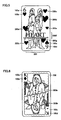
- FIG. 5 is a diagram showing a first specific example of the surface of a printed card.
- FIG. 6 is a diagram showing a second specific example of the surface of the printed card.
- FIG. 7 is a diagram showing a third specific example of the surface of the printed card.
- FIG. 8 is a diagram showing a fourth specific example of the surface of the printed card.
- FIG. 9 is a diagram showing a first specific example of a back image of a card.
- FIG. 10 is a diagram showing a second specific example of the back image of the card.
- FIG. 11 is a diagram showing a specific example of a printer 65 .
- FIG. 12 is a diagram showing a second specific example of the printer.
- FIG. 13 is a plan view of a card base 67 b of FIG. 12 .
- FIG. 14 is a diagram showing a modification of the card base of FIG. 13 .
- FIG. 15 is an X—X sectional view of FIG. 14 .
- FIG. 1 shows a card vending machine 1 for playing cards, in one of the embodiments of the present invention.
- various types of devices are arranged in or on the surface of a box 10 .
- the side of the box 10 facing a user (user) 7 is the front side.
- the left side of the plane is the front side of the box 10 and the right side is the back side of the box 10 in relation to the box 10 of FIG. 1 .
- an arbitrary body can be selected as an object 70 , it is assumed that the whole body of the user 7 is the object 70 in this embodiment.
- a curtain 12 intercepting external light is arranged at the back of the object 70 .
- the curtain 12 is supported by front projecting support frames 13 from an upper portion and a lower portion of the front surface of the box 10 .
- the inner surface of the curtain 12 is provided with a color responsive to a method of synthesizing images. If, for example, chroma key synthesis is used, the overall inner surface of the curtain 12 is painted blue.
- a video camera (or a digital camera) 30 for photographing the object 70 , a control part 5 for receiving an image signal from the camera 30 and synthesizing the images, a display 60 for receiving an image signal from the control part 5 and displaying an image and a printer 65 for receiving a signal of a synthetic image from the control part 5 and printing the synthetic image, are all arranged in the box 10 of the card vending machine 1 .
- a synthetic image which the user 7 observes from the display 60 and the synthetic image printed from the printer 65 are obtained by synthesizing the image of the user 70 and the stored image previously stored in the control part 5 .
- An upper portion of the front surface of the box 10 opens and a transparent plate 11 of glass or plastic is arranged in this opening so that the camera 30 can photograph the object 70 and the user 7 can observe the image displayed on the display 60 .
- a half mirror 61 is arranged at the back of the transparent plate 11 , and the display 60 is arranged under the half mirror 61 .
- the display 60 and the half mirror 61 are so arranged that light emitted from the display 60 is reflected by the half mirror 61 and reaches the user 7 .
- the control part 5 may transmit a prescribed image signal to the display 60 .
- the camera 30 is arranged at the back of the half mirror 61 .
- the camera 30 is arranged to be capable of photographing the whole body of the object 70 , i.e., the user 7 .
- the distance between the camera 30 and the object 70 is preferably short in view of a space for arranging the vending machine.
- a wide angle lens is preferably arranged on the camera 30 .
- the camera 30 is connected to the control part 5 and transmits a photograph signal of the object 70 to the control part 5 .
- the printer 65 receiving the image signal from the control part 5 and printing the image on a card base 67 is arranged in proximity to the front surface in the box 10 , and a pickup part 66 delivering the printed card base 67 from the printer 65 outward from the box 10 is formed on a position of the front surface of the box 10 adjacent to the printer 65 . Paper, plastic or the like is used as the material for the card base 67 .
- An operating part 20 is arranged on the front surface of the box 10 at a position easy to operate for the user 7 .
- the operating part 20 has buttons, levers or the like with which the user 7 performs various operations, forms an operation signal on the basis of the operations of the user 7 and transmits the same to the control part 5 .
- a slot (not shown) is provided on the front surface of the box 10 at a position convenient to the user 7 for inserting a coin (a kind of price), and a coin detection part 25 (see FIG. 2) detecting the inserted coin is arranged on a position in the box 10 adjacent to the slot.
- the coin detection part 25 transmits a detection signal to the control part 5 .
- a speaker 63 (see FIG. 2) receiving a sound signal from the control part 5 and outputting a sound is arranged on a proper position of the front surface of the box 10 .
- FIG. 2 is a block diagram showing the principal structure of the control part 5 .
- the control part 5 includes a personal computer 50 (hereinafter referred to as “PC 50”) executing various types of control.
- the PC 50 receives the operation signal from the operating part 20 , and receives the detection signal from the coin detection part 25 .
- the PC 50 includes a memory 500 storing a plurality of image data and sound data.
- the PC 50 reads specified image data from the memory 50 and transfers the same to a graphic I/F (interface) circuit 51 , while reading specified sound data from the memory 500 and transferring the same to a sound I/F circuit 52 .
- the graphic I/F circuit 51 converts the storage image data received from the PC 50 to a prescribed storage image signal and transmits the same to an image synthesis device 54 and a display selection circuit 55 .
- the sound data which the sound I/F circuit 52 receives from the PC 50 is converted to a prescribed sound signal and transmitted to the speaker 63 , whereby the sound is output from the speaker 63 .
- a demonstration image (hereinafter referred to as “demo image”), a plurality of back images previously printed or to be printed on the back of the card base 67 , a plurality of decorative images to be printed on the surface of the card base 67 and a plurality of index images to be printed on the surface of the card base 67 are included in images stored in the memory 500 as the image data.
- the index images showing marks of the types (club, diamond, heart or spade) to which playing cards belong and ranks (ace, 2 to 10, jack, queen or king) of the playing cards or a joker, are generally printed on the upper left and the lower right of the surfaces of the playing cards.
- the image signal of the object 70 from the camera 30 is received by an image correction device 53 , and the image correction device 53 corrects the image of the object 70 . This is because, when the camera 30 and the object 70 are in the arrangement shown in FIG. 1, the image of the object 70 photographed by the camera 30 has a trapezoidally distorted shape with a large head portion and small leg portions.
- the image signal of the object 70 corrected by the image correction device 53 is transmitted to the image synthesis device 54 .
- the image synthesis device 54 receives the image signal of the object 70 as a first image signal, receives the image signal of the storage image from the graphic I/F circuit 51 as a second image signal, and synthesizes the first image and the second image.
- a method of synthesizing the images is described in Japanese Utility Model Registration No. 3043855, Japanese Utility Model Registration No. 3051776 or the like in detail, and hence detailed description thereof is omitted here.
- the image synthesis device 54 has a plurality of synthesis methods, and it is preferable to select a single synthesis method by an instruction from the PC 50 .
- the synthesized image signal is transmitted to the display selection circuit 55 and the printer 65 .
- the display selection circuit 55 receives the synthetic image signal from the image synthesis device 54 and the storage image signal from the graphic I/F circuit 51 , selects either image signal on the basis of a control signal from the PC 50 and transmits the same to the display 60 .
- the display 60 receives the image signal from the display selection circuit 55 and displays the image.
- the control part 5 includes a printer controller 56 controlling the printer 65 on the basis of a control signal from the PC 50 .
- the printer 65 receives the synthetic image signal from the image synthesis device 54 , stores the data of the synthetic image in a memory 650 built in the printer 65 , forms a print image on the basis of the synthetic image data and prints the print image on the card base 67 of a prescribed size under control by the printer controller 56 .
- Data is directly transferred from the PC 50 to the printer 65 so that printing on the back of the card is performed.
- the data is present in the memory 500 .
- the control part 5 includes various types of counters 58 counting/displaying the number of inserted coins and the like.
- the display selection circuit 55 selects the graphic I/F circuit 51 side by an instruction from the PC 50 .
- the PC 50 reads the data of the demo image previously stored in the memory 500 and transfers the same to the graphic I/F circuit 51 , whereby a demo screen is displayed on the display 60 .
- the PC 50 reads BGM (background music) data previously stored in the memory 500 and transfers the same to the sound I/F circuit 52 , whereby background music is played through the speaker 63 .
- BGM background music
- the PC 50 When the user 7 inserts a coin and the PC 50 receives the detection signal from the coin detection part 25 , the PC 50 reads the image data and the sound data previously stored in the memory 500 at proper timing and transmits the read image data to the display 60 through the graphic I/F circuit 51 and the display selection circuit 55 while transmitting the read sound data to the speaker 63 through the sound I/F circuit 52 for properly supplying an instruction to the user 7 with the image on the display 60 and the sound from the speaker 63 and performing operations shown in FIG. 3 .
- FIG. 3 it first successively reads a plurality of storage image data stored in the memory 500 and makes the display 60 display the same through the graphic I/F circuit 51 and the display selection circuit 55 , and makes the user 7 operate the operating part 20 and select a desired storage image (S 10 ).
- FIG. 4 shows a flow chart illustrating this routine in detail.
- the display 60 first makes the display 60 display a plurality of back images and makes the user 7 select a desired back image (S 101 ).
- the display 60 displays the marks of the types to which the cards belong and the mark of the joker, and makes the user 7 select a desired mark (S 102 ).
- the user determines whether or not the user selects the mark of the joker (S 103 ), for making the display 60 display images indicating the ranks of the cards and making the user 7 select a desired image (S 104 ) when not selecting the joker, while advancing to a next step when selecting the joker.
- the type and the rank of the card the user 7 desires or a supply joker is selected.
- the display 60 displays the plurality of decorative images and makes the user 7 select a desired decorative image (S 105 ).
- the PC 50 may select a decorative image at random in place of the user 7 selecting the decorative image.
- the PC 50 synthesizes the selected index image and decorative image by the selected synthesis method, and makes the display 60 display the synthesized storage image (S 107 ).
- an image of the whole body or an image of the upper half of the body, a single image or a plurality of images, a one-shot image or plural-shot images can be exemplified.
- the user selects one from the aforementioned image structures of the object 70 (S 11 ).
- the PC 50 instructs the image synthesis device 54 to convert the image of the object 70 to the selected image structure and thereafter synthesize the converted image of the object 70 and the synthesized storage image in real time while switching the display selection circuit 55 to the image synthesis device 54 side and making the display 60 display the synthetic image from the image synthesis device 54 in real time (S 12 ).
- the PC 509 instructs the user 7 to pose and then instructs the image synthesis device 54 to stop image synthesis (S 14 ).
- the synthetic image immediately before stoppage is displayed on the display 60 as a static image.
- the user 7 determines whether or not to print the said still image (S 15 ) for pressing a retake button of the operating part 20 when making a retake without printing while pressing a print button of the operating part 20 when performing printing.
- the PC 50 returns to the step S 81 and repeats the aforementioned operations.
- the PC 50 transmits an instruction signal to the printer controller 56 to make the printer 65 print the said still image on the surface of the card base 67 and print the selected back image on the back, and provides the printed card base 67 to the user 7 (S 16 ).
- the memory 500 in the PC 50 stores the game image and the decorative image as digital data and hence it is easy to synthesize the game image and the decorative image.
- the synthesized image is immediately printed in the printer 65 , and hence a card provided with various colors or patterns can be produced at a low cost and in a short time by selection of the user 7 .
- the card vending machine 1 synthesizes the image of the object 70 photographed with the camera 30 on the image obtained by synthesizing the game image and the decorative image in the PC 50 with the image synthesis device 54 and prints the same with the printer 65 , and hence it follows that the degree of freedom of images selectable by the user 7 widens.
- FIG. 5 is a diagram showing a first specific example of the surface of the printed card.
- game images 100 a to 100 d necessary for a game decorative images 200 a to 200 g not directly related to the game and object images (personal images here) 300 are synthesized on the card.
- FIG. 6 is a diagram showing a second specific example of the surface of the printed card.
- game images 100 a to 100 d necessary for a game a decorative image 200 not directly related to the game and object images 300 a and 300 b are synthesized on the card.
- Images of the upper half of the body of the same person are printed to be vertically symmetrical as the object images here.
- FIG. 7 is a diagram showing a third specific example of the surface of the printed card.
- game images 100 a to 100 d necessary for a game, a decorative image 200 not directly related to the game and an object image 300 are synthesized on the card.
- the facial part of a person is printed as the object image here.
- FIG. 8 is a diagram showing a fourth specific example of the surface of the printed card.
- game images 100 a to 100 d necessary for a game and object images 300 are synthesized on the card.
- the user can purchase the cards shown in FIG. 5 to FIG. 8 by self selection.
- FIG. 9 and FIG. 10 are diagrams showing specific examples of the back image of the card.
- images of labyrinths are included in the back images to appear to be patterns to the human eyes at a glance. While FIG. 9 and FIG. 10 are labyrinthine images different from each other, the same appear to be the same patterns to the human eyes at a glance.
- a plurality of card bases 67 on which back images are previously printed may be prepared for selecting a card base 67 on which a back image selected by the user 7 is printed from the card bases 67 and printing a still image on the surface of the selected card base 67 .
- While this embodiment vends a single card used for a card-type plaything, it is also possible to vend cards (if playing cards, 54 cards including two jokers) of a number necessary for playing a game.
- a magnetic recording part capable of rewriting information may be previously arranged on the card base 67 and a function of a magnetic writer writing information in the magnetic recording part may be added to the printer 65 printing the image.
- Another storage part such as an IC can be arranged on the card base in place of a magnetic body. In this case, it follows that a function of writing information in the storage part is added to the printer 65 . In addition, a write part writing information in the storage part 65 ′ can be arranged on the card vending machine 1 independently of the printer 65 .
- this embodiment synthesizes and prints the image of the object 70 photographed with the camera 30
- the effect of the present invention can be attained also when synthesizing and printing the game image and the decorative image selected by the user 7 without synthesizing the object image.
- the camera 30 , the image correction device 53 and the image synthesis device 54 are unnecessary.
- the present invention is applicable also to a device printing an image (image responsive to the taste of the user) that the user obtains by selection, entry, drawing or photographing on a card.
- the printer 65 may perform printing on the card base 67 for obtaining a single card 67 a as shown in FIG. 11, or a printer 65 a performing printing on a card base 67 b including a plurality of cards shown in FIG. 12 may be employed as the printer.
- the user can purchase eight cards at once in the example of FIG. 12 .
- Different images may be printed on the respective ones of the eight cards, or eight identical cards may be printed. Further, the number of the cards is not restricted to eight.
- FIG. 13 is a plan view of the card base 67 b of FIG. 12 .
- the card base 67 b is made of plastic or paper, and the user can cut off cards C 1 to C 4 along dotted lines.
- a card base 67 d of FIG. 14 and FIG. 15 may be employed in place of the card base 67 b of FIG. 13 .
- FIG. 14 is a plan view of the card base 67 d
- FIG. 15 is a sectional view along the line X—X in FIG. 14
- the card base is formed by a mount 403 , an adhesive surface (paste surface) 401 adhering to the mount and a card surface 405 made of plastic or paper.
- the card surface is so notched that the card surface 405 is divided into edge parts E 1 to E 3 and cards C 5 to C 8 .
- the user can obtain the separated cards C 5 to C 8 by peeling the cards C 5 to C 8 from the mount 403 . At this time, it is effective to make paste of the paste surface 401 not adhere to the card.
- the edge parts E 1 to E 3 may not be provided on the card base.
- the present invention as hereinabove described, it is possible to provide a card-type plaything responsive to the taste of the user, and hence the present invention can be advantageously applied to a card-type plaything manufacturing device or the like.
Abstract
Description
Claims (8)
Applications Claiming Priority (3)
| Application Number | Priority Date | Filing Date | Title |
|---|---|---|---|
| JP11/072028 | 1999-03-17 | ||
| JP11072028A JP3009665B1 (en) | 1999-03-17 | 1999-03-17 | Card making machine, card vending machine, card and card type play equipment |
| PCT/JP2000/001562 WO2000054858A1 (en) | 1999-03-17 | 2000-03-15 | Card producing machine, card vending machine, card, and card-type playing device |
Publications (1)
| Publication Number | Publication Date |
|---|---|
| US6659869B1 true US6659869B1 (en) | 2003-12-09 |
Family
ID=13477560
Family Applications (1)
| Application Number | Title | Priority Date | Filing Date |
|---|---|---|---|
| US09/936,760 Expired - Fee Related US6659869B1 (en) | 1999-03-17 | 2000-03-15 | Card manufacturing machine, a card vending machine, and methods therefor |
Country Status (4)
| Country | Link |
|---|---|
| US (1) | US6659869B1 (en) |
| JP (1) | JP3009665B1 (en) |
| TW (2) | TWI247185B (en) |
| WO (1) | WO2000054858A1 (en) |
Cited By (10)
| Publication number | Priority date | Publication date | Assignee | Title |
|---|---|---|---|---|
| US20050035549A1 (en) * | 2003-08-11 | 2005-02-17 | Zeng William B. | Game equipment and games |
| US20050218595A1 (en) * | 2004-03-31 | 2005-10-06 | Walker Information, Inc. | Customer information card game |
| US20050239534A1 (en) * | 2004-04-27 | 2005-10-27 | Carstens Dennis L | Card dispensing machine |
| US20060035695A1 (en) * | 2004-08-16 | 2006-02-16 | Carstens Dennis L | Card dispensing machine |
| US20070232401A1 (en) * | 2006-04-04 | 2007-10-04 | Michael Kidakarn | Method and device for displaying pictures and appealing shapes for electronic game devices and accessories thereof |
| US20070238506A1 (en) * | 2006-04-11 | 2007-10-11 | Ruckle Clyde A | Method and apparatus for card printing |
| US20110114738A1 (en) * | 2006-01-03 | 2011-05-19 | Sandisk Il Ltd. | Automated card customization machine |
| US20140066198A1 (en) * | 2012-08-29 | 2014-03-06 | Wms Gaming, Inc. | Dynamic mapping of photo elements to a game |
| WO2015073200A1 (en) | 2013-11-12 | 2015-05-21 | The United States Playing Card Company | Card back design as a way to prevent card sorting |
| USD896892S1 (en) | 2017-06-28 | 2020-09-22 | Randy Van Gelder | Game equipment including a card and playing board |
Families Citing this family (3)
| Publication number | Priority date | Publication date | Assignee | Title |
|---|---|---|---|---|
| JP2016091442A (en) * | 2014-11-10 | 2016-05-23 | 大日本印刷株式会社 | vending machine |
| JP6428175B2 (en) * | 2014-11-10 | 2018-11-28 | 大日本印刷株式会社 | vending machine |
| KR101844826B1 (en) * | 2015-07-29 | 2018-04-03 | 이종빈 | Removable accessory for eyewear |
Citations (11)
| Publication number | Priority date | Publication date | Assignee | Title |
|---|---|---|---|---|
| JPS55154063A (en) | 1979-05-17 | 1980-12-01 | Seiko Instr & Electronics Ltd | Sealed type alkaline cell |
| JPS5748977U (en) | 1980-09-03 | 1982-03-19 | ||
| JPH0398892A (en) | 1989-09-07 | 1991-04-24 | Kanegafuchi Chem Ind Co Ltd | Supply discharge damper for powder |
| JPH0756056A (en) | 1993-08-17 | 1995-03-03 | Nippon Telegr & Teleph Corp <Ntt> | Optical coupling device |
| US5513117A (en) | 1993-04-30 | 1996-04-30 | Small; Maynard E. | Apparatus and method for electronically dispensing personalized greeting cards and gifts |
| US5687306A (en) * | 1992-02-25 | 1997-11-11 | Image Ware Software, Inc. | Image editing system including sizing function |
| WO1998036565A1 (en) | 1997-02-17 | 1998-08-20 | Sega Enterprises, Ltd. | Moving picture card producing apparatus and storage medium for the apparatus |
| JPH10229535A (en) | 1997-02-17 | 1998-08-25 | Sega Enterp Ltd | Dynamic image card issuing device and storage medium used therefor |
| US5873605A (en) | 1997-01-22 | 1999-02-23 | Kaplan; Kenneth | Personalized postal stamp |
| US5887873A (en) * | 1997-08-21 | 1999-03-30 | Freeman; Jon | Unique deck of playing cards |
| JP3038332B1 (en) | 1999-08-03 | 2000-05-08 | 株式会社メイクソフトウェア | Card making machines, card vending machines and cards |
-
1999
- 1999-03-17 JP JP11072028A patent/JP3009665B1/en not_active Expired - Lifetime
-
2000
- 2000-03-15 US US09/936,760 patent/US6659869B1/en not_active Expired - Fee Related
- 2000-03-15 WO PCT/JP2000/001562 patent/WO2000054858A1/en active Application Filing
- 2000-03-17 TW TW089104905A patent/TWI247185B/en not_active IP Right Cessation
- 2000-03-17 TW TW090115248A patent/TW564328B/en not_active IP Right Cessation
Patent Citations (11)
| Publication number | Priority date | Publication date | Assignee | Title |
|---|---|---|---|---|
| JPS55154063A (en) | 1979-05-17 | 1980-12-01 | Seiko Instr & Electronics Ltd | Sealed type alkaline cell |
| JPS5748977U (en) | 1980-09-03 | 1982-03-19 | ||
| JPH0398892A (en) | 1989-09-07 | 1991-04-24 | Kanegafuchi Chem Ind Co Ltd | Supply discharge damper for powder |
| US5687306A (en) * | 1992-02-25 | 1997-11-11 | Image Ware Software, Inc. | Image editing system including sizing function |
| US5513117A (en) | 1993-04-30 | 1996-04-30 | Small; Maynard E. | Apparatus and method for electronically dispensing personalized greeting cards and gifts |
| JPH0756056A (en) | 1993-08-17 | 1995-03-03 | Nippon Telegr & Teleph Corp <Ntt> | Optical coupling device |
| US5873605A (en) | 1997-01-22 | 1999-02-23 | Kaplan; Kenneth | Personalized postal stamp |
| WO1998036565A1 (en) | 1997-02-17 | 1998-08-20 | Sega Enterprises, Ltd. | Moving picture card producing apparatus and storage medium for the apparatus |
| JPH10229535A (en) | 1997-02-17 | 1998-08-25 | Sega Enterp Ltd | Dynamic image card issuing device and storage medium used therefor |
| US5887873A (en) * | 1997-08-21 | 1999-03-30 | Freeman; Jon | Unique deck of playing cards |
| JP3038332B1 (en) | 1999-08-03 | 2000-05-08 | 株式会社メイクソフトウェア | Card making machines, card vending machines and cards |
Cited By (14)
| Publication number | Priority date | Publication date | Assignee | Title |
|---|---|---|---|---|
| US20050035549A1 (en) * | 2003-08-11 | 2005-02-17 | Zeng William B. | Game equipment and games |
| US20050218595A1 (en) * | 2004-03-31 | 2005-10-06 | Walker Information, Inc. | Customer information card game |
| US7273213B2 (en) * | 2004-03-31 | 2007-09-25 | Walker Information, Inc. | Customer information card game |
| US20050239534A1 (en) * | 2004-04-27 | 2005-10-27 | Carstens Dennis L | Card dispensing machine |
| US20060035695A1 (en) * | 2004-08-16 | 2006-02-16 | Carstens Dennis L | Card dispensing machine |
| US9230389B2 (en) * | 2006-01-03 | 2016-01-05 | Sandisk Il Ltd. | Automated card customization machine |
| US20110114738A1 (en) * | 2006-01-03 | 2011-05-19 | Sandisk Il Ltd. | Automated card customization machine |
| US20070232401A1 (en) * | 2006-04-04 | 2007-10-04 | Michael Kidakarn | Method and device for displaying pictures and appealing shapes for electronic game devices and accessories thereof |
| US20070238506A1 (en) * | 2006-04-11 | 2007-10-11 | Ruckle Clyde A | Method and apparatus for card printing |
| US20140066198A1 (en) * | 2012-08-29 | 2014-03-06 | Wms Gaming, Inc. | Dynamic mapping of photo elements to a game |
| US9286752B2 (en) * | 2012-08-29 | 2016-03-15 | Bally Gaming, Inc. | Dynamic mapping of photo elements to a game |
| WO2015073200A1 (en) | 2013-11-12 | 2015-05-21 | The United States Playing Card Company | Card back design as a way to prevent card sorting |
| EP3068257A4 (en) * | 2013-11-12 | 2017-11-01 | The United States Playing Card Company | Card back design as a way to prevent card sorting |
| USD896892S1 (en) | 2017-06-28 | 2020-09-22 | Randy Van Gelder | Game equipment including a card and playing board |
Also Published As
| Publication number | Publication date |
|---|---|
| JP2000262663A (en) | 2000-09-26 |
| TWI247185B (en) | 2006-01-11 |
| WO2000054858A1 (en) | 2000-09-21 |
| TW564328B (en) | 2003-12-01 |
| JP3009665B1 (en) | 2000-02-14 |
Similar Documents
| Publication | Publication Date | Title |
|---|---|---|
| US6659869B1 (en) | Card manufacturing machine, a card vending machine, and methods therefor | |
| US10857450B1 (en) | Physical-virtual game board and content delivery platform | |
| US20030062675A1 (en) | Image experiencing system and information processing method | |
| US6680715B2 (en) | Electronic baseball card and stand for the same | |
| US20070052167A1 (en) | Radio frequency identification (RFID) poker table | |
| JP5801152B2 (en) | Photo sticker creation apparatus, control method therefor, and program | |
| JP6178464B1 (en) | GAME DEVICE, GAME SYSTEM, AND PROGRAM | |
| JP2007536990A (en) | Collected goods display device | |
| JPH07284129A (en) | Method and apparatus for three-dimensional individual video using three-dimensional model and depth measuring device | |
| JP2004228888A (en) | Automatic photograph vending machine | |
| JP3038332B1 (en) | Card making machines, card vending machines and cards | |
| JP3064074U (en) | Card making machine, card vending machine, card and card type play equipment | |
| JP4140547B2 (en) | Image conversion apparatus, server apparatus including image conversion apparatus, communication terminal apparatus including image conversion apparatus, control method for image conversion apparatus, and computer-readable recording medium | |
| JP2006287943A (en) | Photographing/printing apparatus and method for controlling same | |
| JP6839794B2 (en) | game machine | |
| JP2000268256A (en) | Production of card, card selling method and card | |
| JP2003280084A (en) | Method and machine for automatically vending photographic seal, seal paper unit, and photographic seal sheet | |
| WO2020013202A1 (en) | Game machine and playing medium | |
| JP3031611B2 (en) | Case | |
| JP2001100306A5 (en) | ||
| JPH10229535A (en) | Dynamic image card issuing device and storage medium used therefor | |
| JP3031612B2 (en) | card case | |
| JP2005192045A (en) | Photographic printer, control program for photographic printer, computer-readable recording medium, and control method for photographic printer | |
| JP2005137486A (en) | Dice and dice system | |
| JP4062727B2 (en) | Image printing apparatus and method |
Legal Events
| Date | Code | Title | Description |
|---|---|---|---|
| AS | Assignment |
Owner name: MAKE SOFTWARE CO., LTD., JAPAN Free format text: ASSIGNMENT OF ASSIGNORS INTEREST;ASSIGNOR:AKAMATSU, AKIHIRO;REEL/FRAME:012290/0110 Effective date: 20010903 Owner name: AKAMATSU, AKIHIRO, JAPAN Free format text: ASSIGNMENT OF ASSIGNORS INTEREST;ASSIGNOR:AKAMATSU, AKIHIRO;REEL/FRAME:012290/0110 Effective date: 20010903 |
|
| AS | Assignment |
Owner name: MAKE SOFTWARE CO., LTD., JAPAN Free format text: ASSIGNMENT OF ASSIGNORS INTEREST;ASSIGNOR:AKAMATSU, AKIHIRO;REEL/FRAME:013546/0419 Effective date: 20021115 |
|
| FEPP | Fee payment procedure |
Free format text: PAT HOLDER CLAIMS SMALL ENTITY STATUS, ENTITY STATUS SET TO SMALL (ORIGINAL EVENT CODE: LTOS); ENTITY STATUS OF PATENT OWNER: SMALL ENTITY |
|
| REFU | Refund |
Free format text: REFUND - PAYMENT OF MAINTENANCE FEE, 4TH YEAR, LARGE ENTITY (ORIGINAL EVENT CODE: R1551); ENTITY STATUS OF PATENT OWNER: SMALL ENTITY |
|
| FPAY | Fee payment |
Year of fee payment: 4 |
|
| FEPP | Fee payment procedure |
Free format text: PAYOR NUMBER ASSIGNED (ORIGINAL EVENT CODE: ASPN); ENTITY STATUS OF PATENT OWNER: SMALL ENTITY |
|
| FPAY | Fee payment |
Year of fee payment: 8 |
|
| REMI | Maintenance fee reminder mailed | ||
| LAPS | Lapse for failure to pay maintenance fees | ||
| STCH | Information on status: patent discontinuation |
Free format text: PATENT EXPIRED DUE TO NONPAYMENT OF MAINTENANCE FEES UNDER 37 CFR 1.362 |
|
| FP | Lapsed due to failure to pay maintenance fee |
Effective date: 20151209 |