US6671935B2 - Varying the loop engageability of fastener element arrays - Google Patents
Varying the loop engageability of fastener element arrays Download PDFInfo
- Publication number
- US6671935B2 US6671935B2 US10/277,309 US27730902A US6671935B2 US 6671935 B2 US6671935 B2 US 6671935B2 US 27730902 A US27730902 A US 27730902A US 6671935 B2 US6671935 B2 US 6671935B2
- Authority
- US
- United States
- Prior art keywords
- mold
- array
- fastener
- cavities
- adjacent
- Prior art date
- Legal status (The legal status is an assumption and is not a legal conclusion. Google has not performed a legal analysis and makes no representation as to the accuracy of the status listed.)
- Expired - Lifetime
Links
Images


Classifications
-
- A—HUMAN NECESSITIES
- A44—HABERDASHERY; JEWELLERY
- A44B—BUTTONS, PINS, BUCKLES, SLIDE FASTENERS, OR THE LIKE
- A44B18/00—Fasteners of the touch-and-close type; Making such fasteners
- A44B18/0069—Details
-
- A—HUMAN NECESSITIES
- A44—HABERDASHERY; JEWELLERY
- A44B—BUTTONS, PINS, BUCKLES, SLIDE FASTENERS, OR THE LIKE
- A44B18/00—Fasteners of the touch-and-close type; Making such fasteners
- A44B18/0046—Fasteners made integrally of plastics
- A44B18/0049—Fasteners made integrally of plastics obtained by moulding processes
-
- A—HUMAN NECESSITIES
- A44—HABERDASHERY; JEWELLERY
- A44B—BUTTONS, PINS, BUCKLES, SLIDE FASTENERS, OR THE LIKE
- A44B18/00—Fasteners of the touch-and-close type; Making such fasteners
- A44B18/0046—Fasteners made integrally of plastics
- A44B18/0061—Male or hook elements
-
- A—HUMAN NECESSITIES
- A61—MEDICAL OR VETERINARY SCIENCE; HYGIENE
- A61F—FILTERS IMPLANTABLE INTO BLOOD VESSELS; PROSTHESES; DEVICES PROVIDING PATENCY TO, OR PREVENTING COLLAPSING OF, TUBULAR STRUCTURES OF THE BODY, e.g. STENTS; ORTHOPAEDIC, NURSING OR CONTRACEPTIVE DEVICES; FOMENTATION; TREATMENT OR PROTECTION OF EYES OR EARS; BANDAGES, DRESSINGS OR ABSORBENT PADS; FIRST-AID KITS
- A61F13/00—Bandages or dressings; Absorbent pads
- A61F13/15—Absorbent pads, e.g. sanitary towels, swabs or tampons for external or internal application to the body; Supporting or fastening means therefor; Tampon applicators
- A61F13/56—Supporting or fastening means
- A61F13/62—Mechanical fastening means, ; Fabric strip fastener elements, e.g. hook and loop
- A61F13/622—Fabric strip fastener elements, e.g. hook and loop
- A61F13/625—Fabric strip fastener elements, e.g. hook and loop characterised by the hook
-
- Y—GENERAL TAGGING OF NEW TECHNOLOGICAL DEVELOPMENTS; GENERAL TAGGING OF CROSS-SECTIONAL TECHNOLOGIES SPANNING OVER SEVERAL SECTIONS OF THE IPC; TECHNICAL SUBJECTS COVERED BY FORMER USPC CROSS-REFERENCE ART COLLECTIONS [XRACs] AND DIGESTS
- Y10—TECHNICAL SUBJECTS COVERED BY FORMER USPC
- Y10T—TECHNICAL SUBJECTS COVERED BY FORMER US CLASSIFICATION
- Y10T24/00—Buckles, buttons, clasps, etc.
- Y10T24/27—Buckles, buttons, clasps, etc. including readily dissociable fastener having numerous, protruding, unitary filaments randomly interlocking with, and simultaneously moving towards, mating structure [e.g., hook-loop type fastener]
- Y10T24/2708—Combined with diverse fastener
-
- Y—GENERAL TAGGING OF NEW TECHNOLOGICAL DEVELOPMENTS; GENERAL TAGGING OF CROSS-SECTIONAL TECHNOLOGIES SPANNING OVER SEVERAL SECTIONS OF THE IPC; TECHNICAL SUBJECTS COVERED BY FORMER USPC CROSS-REFERENCE ART COLLECTIONS [XRACs] AND DIGESTS
- Y10—TECHNICAL SUBJECTS COVERED BY FORMER USPC
- Y10T—TECHNICAL SUBJECTS COVERED BY FORMER US CLASSIFICATION
- Y10T24/00—Buckles, buttons, clasps, etc.
- Y10T24/27—Buckles, buttons, clasps, etc. including readily dissociable fastener having numerous, protruding, unitary filaments randomly interlocking with, and simultaneously moving towards, mating structure [e.g., hook-loop type fastener]
- Y10T24/2742—Buckles, buttons, clasps, etc. including readily dissociable fastener having numerous, protruding, unitary filaments randomly interlocking with, and simultaneously moving towards, mating structure [e.g., hook-loop type fastener] having filaments of varied shape or size on same mounting surface
-
- Y—GENERAL TAGGING OF NEW TECHNOLOGICAL DEVELOPMENTS; GENERAL TAGGING OF CROSS-SECTIONAL TECHNOLOGIES SPANNING OVER SEVERAL SECTIONS OF THE IPC; TECHNICAL SUBJECTS COVERED BY FORMER USPC CROSS-REFERENCE ART COLLECTIONS [XRACs] AND DIGESTS
- Y10—TECHNICAL SUBJECTS COVERED BY FORMER USPC
- Y10T—TECHNICAL SUBJECTS COVERED BY FORMER US CLASSIFICATION
- Y10T24/00—Buckles, buttons, clasps, etc.
- Y10T24/27—Buckles, buttons, clasps, etc. including readily dissociable fastener having numerous, protruding, unitary filaments randomly interlocking with, and simultaneously moving towards, mating structure [e.g., hook-loop type fastener]
- Y10T24/2775—Buckles, buttons, clasps, etc. including readily dissociable fastener having numerous, protruding, unitary filaments randomly interlocking with, and simultaneously moving towards, mating structure [e.g., hook-loop type fastener] having opposed structure formed from distinct filaments of diverse shape to those mating therewith
-
- Y—GENERAL TAGGING OF NEW TECHNOLOGICAL DEVELOPMENTS; GENERAL TAGGING OF CROSS-SECTIONAL TECHNOLOGIES SPANNING OVER SEVERAL SECTIONS OF THE IPC; TECHNICAL SUBJECTS COVERED BY FORMER USPC CROSS-REFERENCE ART COLLECTIONS [XRACs] AND DIGESTS
- Y10—TECHNICAL SUBJECTS COVERED BY FORMER USPC
- Y10T—TECHNICAL SUBJECTS COVERED BY FORMER US CLASSIFICATION
- Y10T24/00—Buckles, buttons, clasps, etc.
- Y10T24/27—Buckles, buttons, clasps, etc. including readily dissociable fastener having numerous, protruding, unitary filaments randomly interlocking with, and simultaneously moving towards, mating structure [e.g., hook-loop type fastener]
- Y10T24/2792—Buckles, buttons, clasps, etc. including readily dissociable fastener having numerous, protruding, unitary filaments randomly interlocking with, and simultaneously moving towards, mating structure [e.g., hook-loop type fastener] having mounting surface and filaments constructed from common piece of material
-
- Y—GENERAL TAGGING OF NEW TECHNOLOGICAL DEVELOPMENTS; GENERAL TAGGING OF CROSS-SECTIONAL TECHNOLOGIES SPANNING OVER SEVERAL SECTIONS OF THE IPC; TECHNICAL SUBJECTS COVERED BY FORMER USPC CROSS-REFERENCE ART COLLECTIONS [XRACs] AND DIGESTS
- Y10—TECHNICAL SUBJECTS COVERED BY FORMER USPC
- Y10T—TECHNICAL SUBJECTS COVERED BY FORMER US CLASSIFICATION
- Y10T24/00—Buckles, buttons, clasps, etc.
- Y10T24/33—Buckles, buttons, clasps, etc. having adhesive fastener
-
- Y—GENERAL TAGGING OF NEW TECHNOLOGICAL DEVELOPMENTS; GENERAL TAGGING OF CROSS-SECTIONAL TECHNOLOGIES SPANNING OVER SEVERAL SECTIONS OF THE IPC; TECHNICAL SUBJECTS COVERED BY FORMER USPC CROSS-REFERENCE ART COLLECTIONS [XRACs] AND DIGESTS
- Y10—TECHNICAL SUBJECTS COVERED BY FORMER USPC
- Y10T—TECHNICAL SUBJECTS COVERED BY FORMER US CLASSIFICATION
- Y10T428/00—Stock material or miscellaneous articles
- Y10T428/24—Structurally defined web or sheet [e.g., overall dimension, etc.]
- Y10T428/24008—Structurally defined web or sheet [e.g., overall dimension, etc.] including fastener for attaching to external surface
- Y10T428/24017—Hook or barb
Definitions
- the invention relates to varying the loop engageability of arrays of molded fastener elements, and to the formation of fastener products with exposed grip flanges.
- Hook components for hook and loop fastening include a base from which tiny fastener elements (e.g., hook-shaped or mushroom-shaped elements) extend in an array.
- Hook components with hook-shaped elements may be formed by integrally molding the base and fastener elements in a continuous process employing a mold roll that includes a set of stacked disk-shaped mold plates having fastener-shaped cavities defined at their peripheries, e.g., as described in U.S. Pat. No. 4,794,028 (Fischer), the full disclosure of which is incorporated herein by reference. Hook components may also be injection molded as discrete parts.
- the entire molding region of the mold roll include an even distribution of mold cavities, to promote uniform resin flow and molding pressures over the mold roll surface and also to avoid uneven demolding stresses that could distort the fastener.
- manufacturers either vary the hook density by changing the spacing between adjacent rows of hooks, or replace the mold plates with others having a different hook cavity shape or in-row spacing.
- male fastener elements engage overlying female fastener elements.
- the fastener element When the male element is hook-shaped, the fastener element will individually exhibit directional shear strength, i.e., the shear strength in one direction will be significantly higher than in other directions.
- the array of fastener elements exhibit bi-directional shear strength, i.e., shear strength substantially equal in each of two opposite directions.
- some fastener products include arrays of hooks in which a plurality of rows of fastener elements are arranged so that, in each row, all of the crooks face in the same direction and parallel to the direction of the row, and so that the crooks of adjacent rows face in opposite directions, as shown in FIG. 1 .
- a hook and loop fastener it is often desirable for a hook and loop fastener to have areas in which there is no engagement or a reduced strength engagement of the two sides of the fastener. Such areas may, for example, be associated with a gripping tab to enable the user to more easily separate the two parts of the fastener.
- the present invention features, in several aspects, an array of hook-shaped fastener elements in which the relative spacing between adjacent hooks varies across the array such that some of the fastener elements are rendered less capable of engagement with loop elements than other fastener elements.
- the hook elements are arranged so that some of the hook elements interfere with adjacent hook elements to prevent engagement of the hook elements with loop elements.
- this arrangement can be accomplished by simply adjusting the registration of the mold plates, without the need for other process or tooling changes.
- the invention features an array of hook-shaped fastener elements arranged in parallel rows, each fastener element including a stem and a crook extending from the stem in a predetermined direction to a distal tip.
- the array includes a plurality of rows of fastener elements arranged such that, in each row, all of the crooks face in the same direction and parallel to the direction of the row, and such that the crooks of adjacent rows face in opposite directions.
- the longitudinal spacing between opposing tips of adjacent hooks of adjacent rows is greater, in a first portion of the array, than the longitudinal spacing between opposing tips of adjacent hooks of adjacent rows in a second portion of the array.
- the crooks of the hooks of the first portion of the array are more exposed for engaging loops than the crooks of the hooks of the second portion of the array.
- the crooks of the hooks of adjacent rows in the second portion of the array overlap each other in side profile to interfere with the ability of the crooks to engage loop elements.
- the invention features a fastener product that includes (a) a first fastener component comprising a common base and an array of hook-shaped fastener elements arranged in parallel rows on the common base, and (b) a second fastener element, comprising a common base and a plurality of loops extending from the base for engagement with the hooks.
- Each fastener element includes a stem and a crook extending from the stem in a predetermined direction to a distal tip, and the array includes a plurality of rows of fastener elements, arranged so that, in each row, all of the crooks face in the same direction and parallel to the direction of the row, the crooks of adjacent rows face in opposite directions.
- the longitudinal spacing between opposing tips of adjacent hooks of adjacent rows is greater, in a first portion of the array, than the longitudinal spacing between opposing tips of adjacent hooks of adjacent rows in a second portion of the array.
- the crooks of the hooks of the first portion of the array are more exposed for engaging loops than the crooks of the hooks of the second portion of the array.
- the product includes a strip of fastener tabs or a fastener tape.
- the product includes a personal care product.
- personal care product as used within this patent application, we mean diapers, training pants, swim wear, absorbent underpants, adult incontinence products and feminine hygiene products
- an absorbent article in another aspect, has a flexible sheet for fitting about the body of a wearer, the flexible sheet having a first waist portion and a second waist portion.
- a first fastener element is coupled to the first waist portion, having a common base and a plurality of loops extending from the base.
- a second fastener component is coupled to the second waist portion such that the second fastener component can be brought into contact with the first fastener element when the first waist portion and the second waist portion are fitted about the body of a wearer.
- the second fastener component has a common base and an array of hook-shaped fastener elements arranged in parallel rows on the common base, with the fastener elements arranged as described above so as to enhance the grippability of the second fastener component.
- the invention features a method of forming an array of fastener elements extending from a common base.
- the method includes providing a mold having a mold surface from which an array of fixed mold cavities extend inwardly.
- Each mold cavity defines a hook including a stem and a crook extending from the stem in a predetermined direction, with the array including a plurality of rows of cavities arranged such that, in each row, all of the crooks face in the same direction and parallel to the direction of the row, and with the crooks of adjacent rows face in opposite directions.
- the registration of adjacent rows is adjusted so that the longitudinal spacing between opposing tips of adjacent hooks of adjacent rows in a first portion of the array is greater than the longitudinal spacing between opposing tips of adjacent hooks of adjacent rows' in a second portion of the array, such that the crooks of the hooks of the first portion are more exposed for engaging loops than the crooks of the hooks of the second portion.
- Moldable resin is delivered to the mold, thereby filling the mold cavities and forming the common base.
- the resin is solidified in the cavities to form the fastener elements, which are then removed from their corresponding fixed mold cavities by pulling the common base away from the mold surface.
- the method further includes forming the mold cavities by aligning a plurality of mold plates in face to face relation, registered openings in the aligned mold plates defining the mold cavities.
- the adjusting step may include rotating at least some of the mold plates relative to other mold plates.
- the mold plates are disk-shaped and, when aligned, form a mold roll, the mold cavities extending inwardly from a peripheral surface of the mold roll.
- the delivering step includes, in some embodiments, extruding molten resin into a nip defined between the mold roll and a pressure roll.
- a method for varying the loop engagement characteristics of a molded fastener product produced with a set of mold plates arranged in face-to-face relation to form an array of fastener element mold cavities, with each mold plate defining one of many rows of cavities of the array.
- the method includes positioning the mold plates to purposefully set the longitudinal registration of adjacent rows of the array to decrease longitudinal spacing between adjacent fastener element cavities of adjacent rows, to produce a fastener product with at least a region of an array of fastener elements having a lower loop engageability than a fastener product molded with the mold plates in a different position.
- the invention also features, in another aspect, a mold for forming a fastener device.
- the mold has a mold body with a surface on which a common base can be molded, and defines an array of mold cavities extending into the mold body from the surface.
- the mold cavities are arranged in parallel rows, with each fastener element including a stem and a crook extending from the stem in a predetermined direction to a distal tip.
- the array includes a plurality of rows of fastener elements arranged such that, in each row, all of the crooks face in the same direction and parallel to the direction of the row, with the crooks of adjacent rows facing in opposite directions.
- the longitudinal spacing between opposing tips of adjacent hooks of adjacent rows in a first portion of the array is greater than the longitudinal spacing between opposing tips of adjacent hooks of adjacent rows in a second portion of the array, such that the crooks of the hooks of the first portion are more exposed for engaging loops than the crooks of the hooks of the second portion.
- the invention also features a strip of continuously molded fastener tape and a die cut strip of fastener tabs, having the features described above.
- the invention features an array of hook-shaped fastener elements arranged in parallel rows, each fastener element including a stem and a crook extending from the stem in a predetermined direction to a distal tip, the array having a substantially constant hook density over its surface, and a first portion of the array being constructed to engage loops to a greater extent than a second portion of the array.
- the invention features an array of male fastener elements arranged in parallel rows, each fastener element including a stem and a loop-engaging portion extending from the stem, the array including a plurality of rows of fastener elements.
- the longitudinal spacing between loop-engaging portions of opposing pairs of fastener elements of adjacent rows in a first portion of the array is greater than the longitudinal spacing between loop-engaging portions of opposing pairs of fastener elements of adjacent rows in a second portion of the array, such that the loop-engaging portions of the fastener elements of the first portion are more exposed for engaging loops than the loop-engaging portions of the fastener elements of the second portion.
- the male fastener elements are mushroom shaped.
- the invention also features an array of male fastener elements arranged in parallel rows, each fastener element including a stem and a loop-engaging portion extending from the stem, the array having a substantially constant hook density over its surface, and a first portion of the array being constructed to engage loops to a greater extent than a second portion of the array.
- the invention can provide, inter alia, the advantage of increasing the grippability of engaged fastener tabs without increasing their manufacturing costs. This can be particularly valuable on diapers and other garments, and on fasteners securing emergency medical or fire-fighting equipment.
- the invention can provide the advantage of providing a grip tab with a reduced, but not negligible, amount of loop engageability, such that the grip tab can itself be lightly secured to a loop surface. As applied to diaper tabs, this can make the tab less susceptible to being manipulated by an infant or becoming undesirably released during infant movement.
- the invention is readily implemented by shifting the longitudinal registration of adjacent plates to skew the spacing of adjacent fastener elements to either enhance or degrade their loop engageability.
- registration manipulation is also useful for enabling the molding of fastener products with differing loop engagement characteristics with a single set of mold plates.
- Such plates can be very expensive to manufacture, and a shift in registration can be much less expensive than having multiple sets of plates of different hook cavity shapes or in-row spacings.
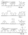
- FIG. 1 is a perspective view of an array of hook elements arranged in a conventional manner.
- FIG. 2 is a top view of an array of hook elements having regions of high and low engageability with loop elements.
- FIGS. 3 and 3A are cross-sectional side views of adjacent rows of hook elements arranged for engagement with loop elements.
- FIG. 3 is a cross-sectional view taken along line 3 — 3 in FIG. 2 .
- FIG. 3A further illustrates engagement of hook elements with loops.
- FIGS. 4 and 4A are cross-sectional side views of two adjacent rows of hook elements in first and second arrays, respectively, of hook elements arranged for diminished loop engageability.
- FIG. 4 is a cross-sectional view taken along line 4 — 4 in FIG. 2 .
- FIG. 4A further illustrates attempted engagement of hook elements with loops.
- FIG. 5 is a schematic top view of the array of FIG. 2 after die cutting to form a strip of fastener tabs.
- FIG. 6 is a perspective view of a diaper equipped with diaper tabs having fastener tabs of the present invention.
- FIG. 7 is a perspective view of the diaper of FIG. 6 being removed from an infant.
- a continuous array 10 of hook-shaped fastener elements 12 extend from an integrally molded, sheet-form base 11 .
- fastener array 10 includes fastening regions 14 , in which the fastener elements 12 are arranged to have a relatively high engageability with mating elements such as loops, and a gripping region 16 , in which the fastener elements 12 are arranged to have a relatively low engageability for mating elements.
- Regions 14 and 16 have parallel longitudinal rows of hooks 12 with the hooks of each row oriented in a uniform direction (as indicated by the arrows in FIG. 2 ).
- the relative engageability with mating elements (e.g., loops) of regions 14 , 16 is determined by the relative spacing between hooks of adjacent rows.
- the hooks of adjacent rows are longitudinally spaced to enable a mating loop to readily extend between the hooks and be snared by the re-entrant hook tips, as is well known in the prior art and illustrated in FIG. 3A, for example.
- FIG. 3 shows another arrangement of hooks arranged to form longitudinal gaps of width “S 1 ” for receiving loops.
- hooks 12 of adjacent rows are longitudinally spaced such that adjacent, opposing crooks longitudinally overlap a distance “S 2 ” (see also FIGS. 4 and 4A) to restrict clearance between the engageable crooks 20 of the hooks 12 .
- S 2 a distance “S 2 ”
- individual loops 32 are generally prevented from passing between the adjacent hook tips 18 and are thus less likely to engage hooks 12 than in the fastening regions of the hook array.
- gripper region 16 is relatively easier to separate from mat 30 than are fastener regions 14 (FIG. 2 ).
- the regions of relatively low engageability 16 can be formed by rotationally indexing the mold plates that form alternating rows of cavities to cause the longitudinal spacing between tips of the hook cavities to be relatively closer than the longitudinal spacing of the tips in the high loop engageability (i.e., normal registration) areas of the mold.
- the array shown in FIG. 2 and described above can be die cut along dashed lines 22 to form a strip of fastener tabs 24 , each fastener tab having a grip portion 26 (shown cross-hatched) that has a relatively low loop engageability and allows the fastener tab to be easily disengaged by pulling the grip portion, and a fastening portion 28 that has a relatively high loop engageability for securing the fastener tab to a loop material.
- the “longitudinal direction” of the product is shown by arrow “A”.
- fastener tabs 24 may be attached to a diaper 40 for fastening the diaper about a wearer.
- Diaper 40 is equipped with a fastener element engaging region having loops 44 for engaging the fastener elements 12 of the fastener tab 24 .
- the user 52 can readily grasp the grip portion 26 of the fastener tab 24 due to its low loop engageability. Subsequently, user 52 can peel the grip portion away from loops 44 to disengage the fastening region 28 of fastener tab 24 from loops 44 .
- the fastener tab With the fastener tab fully released the diaper can be removed from the wearer or re-secured about the wearer by re-engaging the fastener elements 12 of fastener tab 24 with the loops 44 .
- the fastener elements may have multiple, laterally directed tips.
- the fastener element array of varying engageability may be attached to a loop material to form a self-engageable fastener product.
- the fastener elements may be purposefully arranged such that the engageability variation occurs in the direction along which the hook tips extend, although such an arrangement does not share the advantage of being readily molded in rows with Fischer-type hook plates of constant hook cavity spacing.
Abstract
Description
Claims (6)
Priority Applications (1)
| Application Number | Priority Date | Filing Date | Title |
|---|---|---|---|
| US10/277,309 US6671935B2 (en) | 2000-06-02 | 2002-10-22 | Varying the loop engageability of fastener element arrays |
Applications Claiming Priority (2)
| Application Number | Priority Date | Filing Date | Title |
|---|---|---|---|
| US09/585,942 US6543099B1 (en) | 2000-06-02 | 2000-06-02 | Varying the loop engageability of fastener element arrays |
| US10/277,309 US6671935B2 (en) | 2000-06-02 | 2002-10-22 | Varying the loop engageability of fastener element arrays |
Related Parent Applications (2)
| Application Number | Title | Priority Date | Filing Date |
|---|---|---|---|
| US09/276,589 Division US6117329A (en) | 1999-03-25 | 1999-03-25 | Chromatography cartridge end cap fixation |
| US09/585,942 Division US6543099B1 (en) | 2000-06-02 | 2000-06-02 | Varying the loop engageability of fastener element arrays |
Publications (2)
| Publication Number | Publication Date |
|---|---|
| US20030041422A1 US20030041422A1 (en) | 2003-03-06 |
| US6671935B2 true US6671935B2 (en) | 2004-01-06 |
Family
ID=24343625
Family Applications (2)
| Application Number | Title | Priority Date | Filing Date |
|---|---|---|---|
| US09/585,942 Expired - Lifetime US6543099B1 (en) | 2000-06-02 | 2000-06-02 | Varying the loop engageability of fastener element arrays |
| US10/277,309 Expired - Lifetime US6671935B2 (en) | 2000-06-02 | 2002-10-22 | Varying the loop engageability of fastener element arrays |
Family Applications Before (1)
| Application Number | Title | Priority Date | Filing Date |
|---|---|---|---|
| US09/585,942 Expired - Lifetime US6543099B1 (en) | 2000-06-02 | 2000-06-02 | Varying the loop engageability of fastener element arrays |
Country Status (9)
| Country | Link |
|---|---|
| US (2) | US6543099B1 (en) |
| EP (1) | EP1289387A2 (en) |
| JP (1) | JP2003534861A (en) |
| CN (1) | CN1204841C (en) |
| AU (1) | AU2001265316A1 (en) |
| BR (1) | BR0111413A (en) |
| CA (1) | CA2414074A1 (en) |
| MX (1) | MXPA02011981A (en) |
| WO (1) | WO2001093715A2 (en) |
Cited By (18)
| Publication number | Priority date | Publication date | Assignee | Title |
|---|---|---|---|---|
| US20060200951A1 (en) * | 2005-03-11 | 2006-09-14 | Provost George A | Hook fastener components and methods of their manufacture |
| US9254634B2 (en) | 2012-06-18 | 2016-02-09 | R. A. Investment Management S.A.R.L. | Process for making a laminated sheet |
| US9259899B1 (en) | 2015-01-09 | 2016-02-16 | R.A. Investment Management S.A.R.L. | Thin layer laminate |
| US9273741B1 (en) | 2014-09-26 | 2016-03-01 | R.A. Investment Management S.A.R.L. | Composite disc brake backing plate |
| US9291225B2 (en) | 2012-12-07 | 2016-03-22 | R.A. Investment Management S.A.R.L. | Composite disc brake backing plate |
| US9360067B1 (en) | 2015-02-05 | 2016-06-07 | R. A. Investment Management S.A.R.L. | Hybrid laminate |
| WO2016096378A1 (en) | 2014-12-19 | 2016-06-23 | Velcro Industries B.V. | Tamper-evident reusable package closure |
| US9388872B1 (en) | 2015-03-26 | 2016-07-12 | Nucap Industries Inc. | Friction fusion fastening system |
| US9463502B2 (en) | 2012-05-29 | 2016-10-11 | R.A. Investment Management S.A.R.L. | Bulk textured material sheeting |
| US9689450B2 (en) | 2014-09-26 | 2017-06-27 | R.A. Investment Management S.A.R.L. | Composite disc brake backing plate |
| US9856938B2 (en) | 2014-09-26 | 2018-01-02 | R.A. Investment Management S.A.R.L. | Material with variable height barbs |
| US9950495B2 (en) | 2014-07-24 | 2018-04-24 | Nugripmetal S.A.R.L. | System and method for additive manufacturing of a three-dimensional object |
| US10010923B1 (en) | 2017-09-13 | 2018-07-03 | Nugripmetal S.A.R.L. | Textured sheet metal |
| US10150604B2 (en) | 2014-05-12 | 2018-12-11 | Velcro BVBA | Reusable closure system for packaging |
| US10315382B2 (en) | 2016-12-22 | 2019-06-11 | Gripmetal Limited | Process for manufacturing textured laminate sheet |
| US10363176B2 (en) | 2011-12-23 | 2019-07-30 | Kimberly-Clark Worldwide, Inc. | Refastenable disposable garment having a curled edge, and process for making same |
| US11059267B2 (en) | 2013-07-26 | 2021-07-13 | Gripmetal Limited | Metal and graphite laminate |
| US11338658B2 (en) | 2019-01-08 | 2022-05-24 | Truxedo, Inc. | Molded surface fastener |
Families Citing this family (21)
| Publication number | Priority date | Publication date | Assignee | Title |
|---|---|---|---|---|
| NZ515698A (en) * | 2000-05-22 | 2003-03-28 | Miller Herman Inc | Office chair characterised by pivotal and slidable members for restricting forward and rearward movements |
| US6640348B1 (en) * | 2000-11-09 | 2003-11-04 | Velcro Industries B.V. | Forming continuous fastener material |
| CA2448736C (en) | 2001-06-05 | 2010-08-10 | Mikro Systems, Inc. | Methods for manufacturing three-dimensional devices and devices created thereby |
| US7785098B1 (en) | 2001-06-05 | 2010-08-31 | Mikro Systems, Inc. | Systems for large area micro mechanical systems |
| US7059636B2 (en) * | 2002-09-26 | 2006-06-13 | Skjp Holdings, Llc | Seat belt positioning device |
| US8047890B1 (en) * | 2004-02-05 | 2011-11-01 | James Haas | Toy construction set and method |
| FR2870436B1 (en) * | 2004-05-21 | 2006-07-14 | Aplix Sa | FILAMENT WITH INDIVIDUAL FILAMENTS ANCHORS |
| US7608070B2 (en) * | 2004-09-30 | 2009-10-27 | Kimberly-Clark Worldwide, Inc. | Foam-based fasteners |
| US9315663B2 (en) * | 2008-09-26 | 2016-04-19 | Mikro Systems, Inc. | Systems, devices, and/or methods for manufacturing castings |
| US7998548B2 (en) * | 2009-01-19 | 2011-08-16 | Ykk Corporation | Male surface fastener member for use in a cushion body mold and manufacturing method thereof |
| TWI556943B (en) | 2009-01-20 | 2016-11-11 | 傑拉爾德F 羅恰 | Process for forming projections suitable for use in a touch fastener on a diaper |
| CN102341070B (en) | 2009-03-06 | 2014-07-09 | Sca卫生用品公司 | Absorbent article comprising a detachable stiffening element |
| MY160008A (en) | 2009-03-06 | 2017-02-15 | Sca Hygiene Prod Ab | Absorbent article comprising a detachable stiffening element |
| US8636710B2 (en) * | 2009-04-02 | 2014-01-28 | Kimberly-Clark Worldwide, Inc. | Fit maintenance system |
| ES2592683T3 (en) | 2010-07-16 | 2016-12-01 | Gerald Rocha | Dimensionally flexible contact fixator strip |
| US8813824B2 (en) | 2011-12-06 | 2014-08-26 | Mikro Systems, Inc. | Systems, devices, and/or methods for producing holes |
| CN103371891B (en) * | 2012-04-27 | 2016-09-07 | 台湾百和工业股份有限公司 | For the thread gluing sheet of deserted absorbent, its manufacture method and the deserted absorbent having this thread gluing sheet |
| BR112016022703A2 (en) * | 2014-03-31 | 2017-10-17 | Rocha Gerald | detachable contact closure |
| US9282790B2 (en) * | 2014-03-31 | 2016-03-15 | Gerald ROCHA | Deployable touch fastener |
| EP3191061A1 (en) * | 2014-09-12 | 2017-07-19 | The Procter and Gamble Company | Method of making nonwoven material having discrete three-dimensional deformations with wide base openings |
| CN112533571B (en) * | 2018-08-21 | 2022-12-27 | 宝洁公司 | Fastening system comprising nonwoven substrate having integrally formed hooks thereon |
Citations (26)
| Publication number | Priority date | Publication date | Assignee | Title |
|---|---|---|---|---|
| US3312583A (en) | 1963-10-02 | 1967-04-04 | James J Rochlis | Apertured and staggered molded pile product |
| US3408705A (en) | 1966-07-07 | 1968-11-05 | Minnesota Mining & Mfg | Fastener articles |
| US4672722A (en) * | 1986-04-28 | 1987-06-16 | Jmw Textiles | Single tape closure construction |
| US4794028A (en) | 1984-04-16 | 1988-12-27 | Velcro Industries B.V. | Method for continuously producing a multi-hook fastner member and product of the method |
| US4872243A (en) | 1984-04-16 | 1989-10-10 | Velcro Industries B.V. | Multi-hook fastener member |
| EP0464754A1 (en) * | 1990-07-03 | 1992-01-08 | Ykk Corporation | Synthetic resin surface fastener including integrally molded hooks |
| WO1992000023A1 (en) * | 1990-06-28 | 1992-01-09 | The Procter & Gamble Company | Improved process for producing a mechanical fastener and a mechanical fastener produced thereby |
| US5260015A (en) * | 1991-08-16 | 1993-11-09 | Velcro Industries, B.V. | Method for making a laminated hook fastener |
| WO1995001863A1 (en) | 1993-07-06 | 1995-01-19 | Velcro Industries, B.V. | Back-to-back hook fastener |
| US5441687A (en) | 1992-07-22 | 1995-08-15 | Yoshida Kogyo K.K. | Method and apparatus for manufacturing a material-backed engaging member for surface fastener |
| EP0766934A2 (en) | 1995-10-02 | 1997-04-09 | Ykk Corporation | Molded surface fastener having an ornamental pattern, and method of and apparatus for manufacturing same |
| US5625930A (en) * | 1994-08-26 | 1997-05-06 | Ykk Corporation | Molded surface fastener |
| US5664301A (en) * | 1994-12-02 | 1997-09-09 | Ykk Corporation | Molded surface fastener |
| US5685050A (en) * | 1994-07-08 | 1997-11-11 | Ykk Corporation | Hook structure for molded surface fastener |
| US5692271A (en) | 1995-03-07 | 1997-12-02 | Velcro Industries B.V. | Enhanced flexibility fastener, method and apparatus for its making, and product incorporating it |
| US5702797A (en) * | 1995-06-02 | 1997-12-30 | Ykk Corporation | Molded surface fastener and method for manufacturing the same |
| US5755016A (en) | 1996-12-23 | 1998-05-26 | Velcro Industries, B.V. | Hook and loop fastening and the like |
| US5875527A (en) | 1997-08-29 | 1999-03-02 | Velcro Industries B.V. | Fastener element arrangement |
| US5922222A (en) | 1997-09-23 | 1999-07-13 | Velcro Industries B.V. | Forming fastener mold cavities by electro-discharge machining |
| US5933927A (en) | 1997-07-16 | 1999-08-10 | 3M Innovative Properties Company | Finger grip for a fastening system and a method of making the same |
| US6061881A (en) * | 1997-01-20 | 2000-05-16 | Ykk Corporation | Molded engaging member for surface fastener |
| US6063067A (en) * | 1997-07-25 | 2000-05-16 | Ykk Corporation | Disposable diaper and method of folding and fastening the same as waste |
| US6127018A (en) * | 1997-03-10 | 2000-10-03 | Ykk Corporation | Synthetic resin skidproof device |
| US6163939A (en) * | 1996-06-06 | 2000-12-26 | Velcro Industries, B.V. | Molding of fastening hooks and other devices |
| US6258311B1 (en) * | 1997-08-25 | 2001-07-10 | Velcro Industries B.V. | Forming mold cavities |
| US6432339B1 (en) * | 1997-08-25 | 2002-08-13 | Velcro Industries B.V. | Continuous molding of fastener products with a mold belt |
-
2000
- 2000-06-02 US US09/585,942 patent/US6543099B1/en not_active Expired - Lifetime
-
2001
- 2001-06-01 CN CNB018120792A patent/CN1204841C/en not_active Expired - Fee Related
- 2001-06-01 BR BR0111413-1A patent/BR0111413A/en not_active Application Discontinuation
- 2001-06-01 MX MXPA02011981A patent/MXPA02011981A/en not_active Application Discontinuation
- 2001-06-01 JP JP2002501291A patent/JP2003534861A/en active Pending
- 2001-06-01 EP EP01939840A patent/EP1289387A2/en not_active Withdrawn
- 2001-06-01 AU AU2001265316A patent/AU2001265316A1/en not_active Abandoned
- 2001-06-01 WO PCT/US2001/017821 patent/WO2001093715A2/en not_active Application Discontinuation
- 2001-06-01 CA CA002414074A patent/CA2414074A1/en not_active Abandoned
-
2002
- 2002-10-22 US US10/277,309 patent/US6671935B2/en not_active Expired - Lifetime
Patent Citations (27)
| Publication number | Priority date | Publication date | Assignee | Title |
|---|---|---|---|---|
| US3312583A (en) | 1963-10-02 | 1967-04-04 | James J Rochlis | Apertured and staggered molded pile product |
| US3408705A (en) | 1966-07-07 | 1968-11-05 | Minnesota Mining & Mfg | Fastener articles |
| US4794028A (en) | 1984-04-16 | 1988-12-27 | Velcro Industries B.V. | Method for continuously producing a multi-hook fastner member and product of the method |
| US4872243A (en) | 1984-04-16 | 1989-10-10 | Velcro Industries B.V. | Multi-hook fastener member |
| US4672722A (en) * | 1986-04-28 | 1987-06-16 | Jmw Textiles | Single tape closure construction |
| WO1992000023A1 (en) * | 1990-06-28 | 1992-01-09 | The Procter & Gamble Company | Improved process for producing a mechanical fastener and a mechanical fastener produced thereby |
| EP0464754A1 (en) * | 1990-07-03 | 1992-01-08 | Ykk Corporation | Synthetic resin surface fastener including integrally molded hooks |
| US5260015A (en) * | 1991-08-16 | 1993-11-09 | Velcro Industries, B.V. | Method for making a laminated hook fastener |
| US5441687A (en) | 1992-07-22 | 1995-08-15 | Yoshida Kogyo K.K. | Method and apparatus for manufacturing a material-backed engaging member for surface fastener |
| WO1995001863A1 (en) | 1993-07-06 | 1995-01-19 | Velcro Industries, B.V. | Back-to-back hook fastener |
| US5685050A (en) * | 1994-07-08 | 1997-11-11 | Ykk Corporation | Hook structure for molded surface fastener |
| US5625930A (en) * | 1994-08-26 | 1997-05-06 | Ykk Corporation | Molded surface fastener |
| US5664301A (en) * | 1994-12-02 | 1997-09-09 | Ykk Corporation | Molded surface fastener |
| US5692271A (en) | 1995-03-07 | 1997-12-02 | Velcro Industries B.V. | Enhanced flexibility fastener, method and apparatus for its making, and product incorporating it |
| US5702797A (en) * | 1995-06-02 | 1997-12-30 | Ykk Corporation | Molded surface fastener and method for manufacturing the same |
| US5948337A (en) * | 1995-06-02 | 1999-09-07 | Ykk Corporation | Molded surface fastener and method for manufacturing the same |
| EP0766934A2 (en) | 1995-10-02 | 1997-04-09 | Ykk Corporation | Molded surface fastener having an ornamental pattern, and method of and apparatus for manufacturing same |
| US6163939A (en) * | 1996-06-06 | 2000-12-26 | Velcro Industries, B.V. | Molding of fastening hooks and other devices |
| US5755016A (en) | 1996-12-23 | 1998-05-26 | Velcro Industries, B.V. | Hook and loop fastening and the like |
| US6061881A (en) * | 1997-01-20 | 2000-05-16 | Ykk Corporation | Molded engaging member for surface fastener |
| US6127018A (en) * | 1997-03-10 | 2000-10-03 | Ykk Corporation | Synthetic resin skidproof device |
| US5933927A (en) | 1997-07-16 | 1999-08-10 | 3M Innovative Properties Company | Finger grip for a fastening system and a method of making the same |
| US6063067A (en) * | 1997-07-25 | 2000-05-16 | Ykk Corporation | Disposable diaper and method of folding and fastening the same as waste |
| US6258311B1 (en) * | 1997-08-25 | 2001-07-10 | Velcro Industries B.V. | Forming mold cavities |
| US6432339B1 (en) * | 1997-08-25 | 2002-08-13 | Velcro Industries B.V. | Continuous molding of fastener products with a mold belt |
| US5875527A (en) | 1997-08-29 | 1999-03-02 | Velcro Industries B.V. | Fastener element arrangement |
| US5922222A (en) | 1997-09-23 | 1999-07-13 | Velcro Industries B.V. | Forming fastener mold cavities by electro-discharge machining |
Cited By (31)
| Publication number | Priority date | Publication date | Assignee | Title |
|---|---|---|---|---|
| US7516524B2 (en) * | 2005-03-11 | 2009-04-14 | Velcro Industries B.V. | Hook fastener components and methods of their manufacture |
| US20060200951A1 (en) * | 2005-03-11 | 2006-09-14 | Provost George A | Hook fastener components and methods of their manufacture |
| US11253408B2 (en) | 2011-12-23 | 2022-02-22 | Kimberly-Clark Worldwide, Inc. | Refastenable disposable garment having a curled edge, and process for making same |
| US10363176B2 (en) | 2011-12-23 | 2019-07-30 | Kimberly-Clark Worldwide, Inc. | Refastenable disposable garment having a curled edge, and process for making same |
| US11198170B2 (en) | 2012-05-29 | 2021-12-14 | Gripmetal Limited | Bulk textured material sheeting |
| US11858025B2 (en) | 2012-05-29 | 2024-01-02 | Gripmetal Limited | Bulk textured material sheeting |
| US9463502B2 (en) | 2012-05-29 | 2016-10-11 | R.A. Investment Management S.A.R.L. | Bulk textured material sheeting |
| US10335847B2 (en) | 2012-05-29 | 2019-07-02 | Gripmetal Limited | Bulk textured material sheeting |
| US9707733B2 (en) | 2012-06-18 | 2017-07-18 | R.A. Investment Management S.A.R.L. | Process for making a laminated sheet |
| US9254634B2 (en) | 2012-06-18 | 2016-02-09 | R. A. Investment Management S.A.R.L. | Process for making a laminated sheet |
| US9291225B2 (en) | 2012-12-07 | 2016-03-22 | R.A. Investment Management S.A.R.L. | Composite disc brake backing plate |
| US9670976B2 (en) | 2012-12-07 | 2017-06-06 | R.A. Investment Management S.A.R.L. | Composite disc brake backing plate |
| US10316911B2 (en) | 2012-12-07 | 2019-06-11 | Gripmetal Limited | Composite disc brake backing plate |
| US11059267B2 (en) | 2013-07-26 | 2021-07-13 | Gripmetal Limited | Metal and graphite laminate |
| US10150604B2 (en) | 2014-05-12 | 2018-12-11 | Velcro BVBA | Reusable closure system for packaging |
| US9950495B2 (en) | 2014-07-24 | 2018-04-24 | Nugripmetal S.A.R.L. | System and method for additive manufacturing of a three-dimensional object |
| US11267219B2 (en) | 2014-07-24 | 2022-03-08 | Gripmetal Limited | System and method for additive manufacturing of a three-dimensional object |
| US9856938B2 (en) | 2014-09-26 | 2018-01-02 | R.A. Investment Management S.A.R.L. | Material with variable height barbs |
| US9689450B2 (en) | 2014-09-26 | 2017-06-27 | R.A. Investment Management S.A.R.L. | Composite disc brake backing plate |
| US9273741B1 (en) | 2014-09-26 | 2016-03-01 | R.A. Investment Management S.A.R.L. | Composite disc brake backing plate |
| US10088004B2 (en) | 2014-09-26 | 2018-10-02 | Nugripmetal S.A.R.L. | Composite disc brake backing plate |
| WO2016096378A1 (en) | 2014-12-19 | 2016-06-23 | Velcro Industries B.V. | Tamper-evident reusable package closure |
| US10167111B2 (en) | 2014-12-19 | 2019-01-01 | Velcro BVBA | Tamper-evident reusable package closure |
| US9259899B1 (en) | 2015-01-09 | 2016-02-16 | R.A. Investment Management S.A.R.L. | Thin layer laminate |
| US9360067B1 (en) | 2015-02-05 | 2016-06-07 | R. A. Investment Management S.A.R.L. | Hybrid laminate |
| US9388872B1 (en) | 2015-03-26 | 2016-07-12 | Nucap Industries Inc. | Friction fusion fastening system |
| US11214039B2 (en) | 2016-12-22 | 2022-01-04 | Gripmetal Limited | Process for manufacturing textured laminate sheet |
| US10315382B2 (en) | 2016-12-22 | 2019-06-11 | Gripmetal Limited | Process for manufacturing textured laminate sheet |
| US11045860B2 (en) | 2017-09-13 | 2021-06-29 | Gripmetal Limited | Textured sheet metal, and process and apparatus for producing textured sheet metal |
| US10010923B1 (en) | 2017-09-13 | 2018-07-03 | Nugripmetal S.A.R.L. | Textured sheet metal |
| US11338658B2 (en) | 2019-01-08 | 2022-05-24 | Truxedo, Inc. | Molded surface fastener |
Also Published As
| Publication number | Publication date |
|---|---|
| CN1204841C (en) | 2005-06-08 |
| WO2001093715A3 (en) | 2002-05-23 |
| MXPA02011981A (en) | 2004-05-05 |
| WO2001093715A2 (en) | 2001-12-13 |
| AU2001265316A1 (en) | 2001-12-17 |
| US6543099B1 (en) | 2003-04-08 |
| CA2414074A1 (en) | 2001-12-13 |
| CN1440246A (en) | 2003-09-03 |
| BR0111413A (en) | 2005-01-18 |
| EP1289387A2 (en) | 2003-03-12 |
| JP2003534861A (en) | 2003-11-25 |
| US20030041422A1 (en) | 2003-03-06 |
Similar Documents
| Publication | Publication Date | Title |
|---|---|---|
| US6671935B2 (en) | Varying the loop engageability of fastener element arrays | |
| US6588073B1 (en) | Male fasteners with angled projections | |
| US5692271A (en) | Enhanced flexibility fastener, method and apparatus for its making, and product incorporating it | |
| US6623469B1 (en) | Refastenable mechanical fastening system and process of manufacture therefor | |
| US6526633B2 (en) | Hook fasteners and methods of manufacture | |
| EP0381087B1 (en) | Refastenable mechanical fastening system and process of manufacture thereof | |
| AU676747B1 (en) | Molded surface fastener | |
| US7052638B2 (en) | Hook and loop fastener | |
| US5664302A (en) | Method for manufacturing refastenable fastening systems including a female loop fastening component and the products produced therefrom | |
| EP1372561B1 (en) | Skin-friendly hook fastening component | |
| EP2563177B1 (en) | Male touch fastener element | |
| WO1996027307B1 (en) | Enhanced flexibility fastener, method and apparatus for its making, and product incorporating it | |
| EP0711518B1 (en) | Hook structure for molded surface fastener | |
| WO1996027307A9 (en) | Enhanced flexibility fastener, method and apparatus for its making, and product incorporating it | |
| US9538816B2 (en) | Forming touch fasteners on substrates | |
| EP2342988B1 (en) | Direct hook engagement | |
| US20030040730A1 (en) | Secondary attachment system for personal care article | |
| GB2397620A (en) | Male fasteners with angled projections |
Legal Events
| Date | Code | Title | Description |
|---|---|---|---|
| STCF | Information on status: patent grant |
Free format text: PATENTED CASE |
|
| FEPP | Fee payment procedure |
Free format text: PAYOR NUMBER ASSIGNED (ORIGINAL EVENT CODE: ASPN); ENTITY STATUS OF PATENT OWNER: LARGE ENTITY |
|
| FPAY | Fee payment |
Year of fee payment: 4 |
|
| FPAY | Fee payment |
Year of fee payment: 8 |
|
| FPAY | Fee payment |
Year of fee payment: 12 |
|
| AS | Assignment |
Owner name: VELCRO INDUSTRIES B.V., NETHERLANDS Free format text: ASSIGNMENT OF ASSIGNORS INTEREST;ASSIGNORS:FILION, SCOTT M.;SCHMIDT, RICHARD J.;SIGNING DATES FROM 20000808 TO 20010126;REEL/FRAME:036506/0665 |
|
| AS | Assignment |
Owner name: VELCRO BVBA, BELGIUM Free format text: ASSIGNMENT OF ASSIGNORS INTEREST;ASSIGNOR:VELCRO INDUSTRIES B.V.;REEL/FRAME:038528/0767 Effective date: 20160415 |