US6672336B2 - Dual random access, three-way rotary valve apparatus - Google Patents
Dual random access, three-way rotary valve apparatus Download PDFInfo
- Publication number
- US6672336B2 US6672336B2 US09/998,529 US99852901A US6672336B2 US 6672336 B2 US6672336 B2 US 6672336B2 US 99852901 A US99852901 A US 99852901A US 6672336 B2 US6672336 B2 US 6672336B2
- Authority
- US
- United States
- Prior art keywords
- rotor
- fluid communication
- stator
- outlet
- channel set
- Prior art date
- Legal status (The legal status is an assumption and is not a legal conclusion. Google has not performed a legal analysis and makes no representation as to the accuracy of the status listed.)
- Expired - Lifetime, expires
Links
Images


Classifications
-
- F—MECHANICAL ENGINEERING; LIGHTING; HEATING; WEAPONS; BLASTING
- F16—ENGINEERING ELEMENTS AND UNITS; GENERAL MEASURES FOR PRODUCING AND MAINTAINING EFFECTIVE FUNCTIONING OF MACHINES OR INSTALLATIONS; THERMAL INSULATION IN GENERAL
- F16K—VALVES; TAPS; COCKS; ACTUATING-FLOATS; DEVICES FOR VENTING OR AERATING
- F16K11/00—Multiple-way valves, e.g. mixing valves; Pipe fittings incorporating such valves
- F16K11/02—Multiple-way valves, e.g. mixing valves; Pipe fittings incorporating such valves with all movable sealing faces moving as one unit
- F16K11/06—Multiple-way valves, e.g. mixing valves; Pipe fittings incorporating such valves with all movable sealing faces moving as one unit comprising only sliding valves, i.e. sliding closure elements
- F16K11/072—Multiple-way valves, e.g. mixing valves; Pipe fittings incorporating such valves with all movable sealing faces moving as one unit comprising only sliding valves, i.e. sliding closure elements with pivoted closure members
- F16K11/074—Multiple-way valves, e.g. mixing valves; Pipe fittings incorporating such valves with all movable sealing faces moving as one unit comprising only sliding valves, i.e. sliding closure elements with pivoted closure members with flat sealing faces
-
- Y—GENERAL TAGGING OF NEW TECHNOLOGICAL DEVELOPMENTS; GENERAL TAGGING OF CROSS-SECTIONAL TECHNOLOGIES SPANNING OVER SEVERAL SECTIONS OF THE IPC; TECHNICAL SUBJECTS COVERED BY FORMER USPC CROSS-REFERENCE ART COLLECTIONS [XRACs] AND DIGESTS
- Y10—TECHNICAL SUBJECTS COVERED BY FORMER USPC
- Y10T—TECHNICAL SUBJECTS COVERED BY FORMER US CLASSIFICATION
- Y10T137/00—Fluid handling
- Y10T137/8593—Systems
- Y10T137/86493—Multi-way valve unit
- Y10T137/86501—Sequential distributor or collector type
-
- Y—GENERAL TAGGING OF NEW TECHNOLOGICAL DEVELOPMENTS; GENERAL TAGGING OF CROSS-SECTIONAL TECHNOLOGIES SPANNING OVER SEVERAL SECTIONS OF THE IPC; TECHNICAL SUBJECTS COVERED BY FORMER USPC CROSS-REFERENCE ART COLLECTIONS [XRACs] AND DIGESTS
- Y10—TECHNICAL SUBJECTS COVERED BY FORMER USPC
- Y10T—TECHNICAL SUBJECTS COVERED BY FORMER US CLASSIFICATION
- Y10T137/00—Fluid handling
- Y10T137/8593—Systems
- Y10T137/86493—Multi-way valve unit
- Y10T137/86863—Rotary valve unit
Definitions
- the present invention relates to multi-function rotary valves and, more particularly, relates to a random-access, dual, three-way, rotary switching valve for use with high-pressure liquid chromatography (HPLC), other analytical methods and the like.
- HPLC high-pressure liquid chromatography
- a “three-way” switching valve provides a means for selectively routing a fluid input flow to the valve to one of two alternate output flows from the valve.
- a “rotary” valve is of the type wherein fluid flow is directed by rotating a valve rotor element to discrete angular positions relative to a stationary valve stator element.
- a “dual” rotary valve provides two valves in one valve body, both simultaneously operated by the positioning of the valve rotor.
- Rotary switching valves are commonly used, for example, in HPLC and other analytical methods to selectively direct a flow stream of one or more fluids along alternate paths to an analytical device or containment vessel.
- One conventional type of dual, three-way, switching valve 220 includes a disc-shaped rotor with a set of rotor grooves in the front face of the rotor that contacts, in a fluid-tight manner, the face of a cylindrically shaped stator body at a rotor-stator interface.
- Inlet passages and outlet passages longitudinally bored through the stator body to the rotor-stator interface, are selectively fluidly coupled through the rotor grooves corresponding to the rotation of the rotor relative to the stator.
- Pivoting of the rotor enables the rotor grooves to fluidly couple selected passages of the stator, depending on their placement on the rotor and the angular position of the valve rotor.
- Model 7030 of Rheodyne, L. P. is an example of this type of switching valve.
- valve 220 has a stator element 222 and a rotor 224 .
- the stator element 222 defines a stator face 226 that opposes and is in fluid-tight contact with a rotor face 228 defined by rotor 224 .
- the stator element 222 further defines a first inlet passage 230 that has one end 232 adapted to fluidly couple to a first fluid source (Not Shown) supplying a first fluid and has an opposite first inlet port 236 terminating at stator face 226 .
- stator element 222 further defines a second inlet passage 238 that has one end 240 adapted to fluidly couple to a second fluid source (Not Shown) supplying a second fluid and has an opposite second inlet port 244 terminating at stator face 226 .
- the stator element 222 further defines a first outlet passage A, a second outlet passage B, a third outlet passage C, and a fourth outlet passage D, all in fluid communication with stator face 226 .
- the rotor 224 defines a first rotor groove 246 and a second rotor groove 248 , both formed in the rotor face and adapted to transfer fluid.
- a fluid-tight seal is formed at the rotor-stator interface thus providing for the containment of any fluid within the rotor grooves and avoiding fluid leakage between the rotor and stator at the rotor-stator interface.
- Rotor 224 is rotatably movable about an axis of rotation 250 , normal to and at the center of stator face 226 , between two discrete angular positions with respect to stator element 222 (FIGS. 2 A and 2 B).
- FIGS. 2A-2B show schematic views of the rotor-stator interface of the prior art valve of FIG. 1 in two discrete modes of operation, looking at the stator surface 226 , with the rotor 224 being transparent.
- the valve 220 provides two position fluid output switching of two separate input fluids.
- the two modes of operation depicted correspond to the positioning of controlling rotor 224 in one of its two discrete angular positions indicated by markings “1” and “2” on rotor face 228 .
- the first fluid and the second fluid from the first and second fluid source, respectively are pressurized by a suitable means, such as a pump (Not Shown), to provide a motivating force for fluid flow.
- inlet ports 236 and 244 and outlet passages A, B, C, and D as well as rotor grooves 246 and 248 are all contained on an imaginary circle 252 concentric with axis 250 at the rotor-stator interface. All inlet and outlet passages are circumferentially spaced apart at an arc angle of about 60° about imaginary circle 252 .
- the first rotor groove 246 fluidly couples the first inlet passage 230 to the first outlet passage A
- the second rotor groove 248 fluidly couples the second inlet passage 238 to the third outlet passage C. Accordingly, as the first fluid flows through the first inlet passage 230 in the direction of arrow 234 of FIG. 1, the first rotor groove 246 directs the flow out of the first outlet passage A in the direction of arrow 235 .
- the second rotor groove 248 directs the flow out of the second outlet passage C in the direction of arrow 243 .
- the rotor face is rotated 60° counterclockwise (Position “1” of rotor grooves 246 and 248 is shown in dashed line).
- the first rotor groove 246 as shown, fluidly couples the first inlet passage 230 to the second outlet passage B, and similarly the second rotor groove 248 fluidly couples the second inlet passage 238 to the fourth outlet passage D.
- Table 1 summarizes the operating modes of the prior art valve 220 when rotor face 228 is placed in each of its two discrete operating positions “1” and “2”.
- switching valve 220 to selectively direct the flow of the first fluid to the first outlet passage A while the flow of the second fluid is directed to the third outlet passage C (i.e., position “1”) or, alternatively, to direct the flow of the first fluid to second outlet passage B while the flow of the second fluid is directed to the fourth outlet passage D (i.e., position “2”).
- Simple reciprocation of rotor 224 between each of the two discrete operating positions “1” and “2” of valve 220 relocates the rotor grooves 246 and 248 to fluidly connect the two inlet passages 230 and 238 to different pairs of outlet passages A/C and B/D.
- first and second fluids selective directing of the first and second fluids is accomplished in a “tandem” or “linked” operation. That is, in a mutually exclusive manner, the second fluid is directed to third outlet passage C only when the first fluid is directed to first outlet passage A when the rotor is placed in first discrete position “1”, and the second fluid is directed to fourth outlet passage D only when the first fluid is directed to second outlet passage B when the rotor 224 is placed in second discrete position “2”. It is not possible with prior art valve 220 for the first fluid to randomly access one of either the first outlet passage A or the second outlet passage B and, at the same time, for the second fluid to randomly access, independently, one of either the third outlet passage C or the fourth outlet passage D. For example, with valve 220 , it is not possible for the first fluid to access first outlet passage A while the second fluid accesses fourth outlet passage D.
- the present invention provides a random access, dual, three-way, fluid switching rotor valve that selectively directs the flow of a first fluid to either one of at least two alternate outlet passages and, simultaneously and independently, selectively directs the flow of a second fluid to either one of at least two different outlet passages. Accordingly, unlike the previous dual, three-way rotor valves, any combination of fluid flows between the outlets is attainable.
- the valve apparatus includes a stator body having a stator face lying in an interface plane and a rotor element having a rotor face oriented in the interface plane in opposed relationship to and contacting with the stator face in a fluid-tight manner.
- the rotor element is pivotable about a rotational axis for rotational movement of the rotor face to at least four discrete angular positions relative to the stator face.
- the stator element defines two independent inlet passages each having one end fluidly coupled to a respective fluid source for supplying a fluid. Both inlet passages further include opposite inlet ports which terminate at the stator face. Additionally, the stator element further defines at least three stator slots, and at least four independent outlet passages each of which is in fluid communication with the stator face. The first two outlet passages correspond to the first inlet passage, while the last two outlet passages correspond to the second inlet passage.
- the rotor element includes a rotor face which defines at least two rotor grooves. This face is rotatably mounted to the stator face in a fluid-tight manner, and between a first, a second, a third and a fourth rotor position.
- the inlet ports, the outlet passages, and the stator slots of the stator element, and rotor grooves of the rotor element and stator slots collectively form a channel set which is arranged such that, in the first discrete rotor position, the first inlet port is fluidly coupled with the first outlet passage through a rotor groove and the second inlet port is coupled in fluid communication with the third outlet passage through another rotor groove. In the second discrete position, the first inlet port is maintained in fluid communication with the first outlet passage, while the second inlet port is fluidly coupled to the fourth outlet passage.
- the first inlet port is then fluidly coupled to second outlet passage through a rotor groove and the second inlet port is coupled in fluid communication with the third outlet passage through another rotor groove.
- the first inlet port is maintained in fluid communication with the second outlet passage, while the second inlet port is fluidly coupled to fourth outlet passage.
- the first inlet port of the stator is disposed at the rotational axis of the rotor element which is also the central longitudinal axis normal to the stator face.
- the second inlet port by comparison, is disposed on a first imaginary circle lying in the interface plane and co-axial to the rotor valve rotational axis.
- the stator face further defines a first outlet port of the first outlet passage, and a second outlet port of the second outlet passage, both of which lie in the first imaginary circle.
- a third outlet port of the third outlet passage, and a fourth outlet port of the fourth outlet passages both lie on a second imaginary circle of the interface plane which is concentric to the first imaginary circle.
- the second imaginary circle is of a diameter larger than that of first imaginary circle.
- a first stator slot formed in the stator face lies in the first imaginary circle and is in fluid communication with the first outlet port, while a second stator slot is formed in the stator face, in the first imaginary circle, and is in fluid communication with the second outlet port.
- the stator face further includes a third stator slot lying on the first imaginary circle which is in fluid communication with the second inlet port.
- the rotor face includes a first rotor groove which provides fluid communication between the first inlet passage and the first and second outlet passages, while a second and third rotor groove provide fluid communication between the second inlet passage and the third and fourth outlet passages, depending upon which discrete rotor position (i.e., first through fourth) the rotor valve is disposed.
- the first rotor groove extends substantially radially from the rotational axis of the rotor valve to the first imaginary circle, having an inlet end in continuous fluid communication with the first inlet port.
- An outlet end of the first rotor groove is contained in the first imaginary circle, and in fluid communication with the first stator slot when the rotor is placed in the first or second discrete position.
- the first inlet port is maintained fluidly coupled to the first outlet passage when the rotor is placed in the first or second discrete position.
- the outlet end of the first rotor groove is maintained in fluid communication with the second stator slot.
- the first inlet port is maintained fluidly coupled to the second outlet passage when the rotor is placed in the third or fourth discrete position.
- both the second and third rotor grooves extend in a direction substantially radially from the rotational axis of the rotor element.
- a respective inlet end thereof lies on the first imaginary circle and a respective outlet end thereof lies on the second imaginary circle.
- the second and third rotor grooves are preferably identical in configuration, but are spaced-apart angularly about the rotational axis.
- the inlet end of the second rotor slot is maintained in fluid communication with the second inlet passage, via the third stator slot.
- the outlet end of the second rotor groove is in communication with the third outlet port while, in the second discrete rotor position, the outlet end of the second rotor groove is in communication with the fourth outlet port.
- the inlet end of the third rotor slot is maintained in fluid communication with the second inlet passage, via the third stator slot.
- the outlet end of the third rotor groove is in communication with the third outlet port while, in the fourth discrete rotor position, the outlet end of the third rotor groove is in communication with the fourth outlet port.
- FIG. 1 is an exploded, isometric view of a prior art dual, three-way, rotary-switching valve.
- FIGS. 2A and 2B is series of schematic views of the rotor-stator interface plane of the prior art dual, three-way switching valve of FIG. 1 in a first and second discrete rotor position.
- FIG. 3 is a schematic diagram of a system incorporating a dual, three-way, rotary-switching valve constructed in accordance with the present invention.
- FIG. 4 is an exploded, isometric view of one embodiment of a dual, three-way, rotary-switching valve constructed in accordance with the present invention in a first operating mode.
- FIGS. 5A-5E is series of schematic views of the rotor-stator interface plane of the dual, three-way switching valve of FIG. 4 illustrating operation in a first through fourth discrete rotor position.
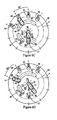
- FIGS. 6A-6D is a series of schematic views of the rotor-stator interface plane of an alternative embodiment dual, three-way switching valve illustrating operation in a first through fourth discrete rotor position.
- the valve includes a stator element 22 defining a first inlet passage 32 fluidly coupled to a first fluid source 35 and having a first inlet port 38 terminating at a stator face 24 lying in an interface plane.
- a second inlet passage 40 of the stator element 22 is fluidly coupled to a second fluid source 37 , and includes a second inlet port 46 terminating at the stator face 24 .
- the stator element 22 further defines a first outlet passage A, a second outlet passage B, a third outlet passage C and a fourth outlet passage D, each in fluid communication with the stator face 24 .
- the valve apparatus 20 further includes a rotor element 26 which defines a rotor face 28 oriented in the interface plane in opposed relationship to and contacting the stator face 24 in a fluid-tight manner.
- the rotor element 26 is rotatably movable about a rotational axis 30 , relative to the stator face 24 for rotational movement of the rotor face 28 to at least a discrete first rotor position (FIG. 5 A), a second rotor position (FIG. 5 B), a third rotor position (FIG. 5 C), and a fourth rotor position (FIG. 5 D).
- the rotor face 28 and the stator face 24 cooperatively define a channel set 39 enabling fluid communication between the first fluid source 35 and one of the first outlet passage A and second outlet passage B, and enabling fluid communication between the second fluid source 37 and one of the third outlet passage C and fourth outlet passage D.
- the channel set 39 fluidly couples the first inlet port 38 to the first outlet passage A and fluidly couples the second inlet port 46 to the third outlet passage C.
- the channel set again fluidly couples the first inlet port 38 to the first outlet passage A, but then fluidly couples the second inlet port 46 to the fourth outlet passage D.
- the channel set 39 now fluidly couples the first inlet port 38 to the second outlet passage B, while fluidly coupling the second inlet port 46 to the third outlet passage C.
- the channel set again fluidly couples the first inlet port 38 to the second outlet passage B, but then fluidly couples the second inlet port 46 to the fourth outlet passage D.
- a dual, random access, three-way, rotary valve which enables selective fluid switching of a first fluid to either one of at least two different outlet passages for the first three-way valve, and of a second fluid to either one of at least two different outlet passages for the second three-way valve.
- complete fluid distribution versatility between the first and the second fluid sources, and their corresponding first and second outlet passages, and the third and fourth outlet passages is disclosed.
- valve apparatus 20 of the present invention is particularly suitable for use with high-pressure liquid chromatography (HPLC), high-speed mass spectrophotometry, or other analytical methods in, for example, sample preparation or in directing analytical samples to several alternative detectors.
- Stepper motors are often used as a means to actuate the valve in robotic analytical systems.
- Suitable fluid pressurization means such as pumps are utilized to provide fluid flow through the valve, preferably by means of a high-pressure pump typically delivering continuously metered pressure ranging from about 1000 PSI to about 6000 PSI.
- the rotary valve apparatus of the present invention is operable in four distinct modes and provides fluid output switching functions on two separate valve input fluids.
- the valve receives two different fluid flows from two different sources and provides a set of channels (i.e., the channel set 39 ) which cooperate to direct these two fluids along alternate fluid output paths depending on the switching mode to which the valve is set.
- the two fluids are not intermingled, as the grooves and passages of the first valve portion are only used in the first valve.
- the four modes of operation correspond to the positioning of a valve rotor element in one of four discrete angular positions relative to a stationary stator element of the valve.
- a fifth position a closed position
- This new blocked position is not normally found in three-way valves and may be beneficial to the user. Both inlet flows are blocked, but the fluids in the grooves 76 and 52 can intermingle by diffusion.
- This closed position is a tandem closed and not Random Access.
- stator element 22 and the rotor element 26 are preferably cylindrically shaped, having a stator face 24 and a rotor face 28 , respectively, lying in an interface plane in opposed relationship to one another.
- Rotor element 26 is pivotable about a rotational axis 30 for rotational movement of the rotor element 26 relative to the stator element 22 to a selected one of four discrete angular positions shown in FIGS. 5A-5D, and as indicated by the markings “1”, “2”, “3”, “4”.
- the four discrete angular positions of rotor element 26 are preferably positioned apart by an arc angle of about 36°.
- This same design sequence could be provided by 45° separation lines (i.e., the four discrete angular positions spaced at 45° arc angles) (not shown), but in this mode, the second and third rotor grooves would contact the first and second stator slots in positions one and four, allowing intermixing of the two fluids by dispersion. If this is allowed, a more compact design would result.
- the stator portion of the channel set 39 includes two tubular fluid inlet passages 32 , 40 longitudinally extending through stator element 22 and adapted to convey a fluid.
- a first inlet passage 32 has one open end 34 adapted to fluidly couple to a first fluid source 35 for supplying a first fluid (in the direction of arrow 41 ) in FIG. 4 and, an opposite first inlet port 38 terminating at stator face 24 .
- a second inlet passage 40 is provided also extending longitudinally therethrough which includes one open end 42 adapted to fluidly couple to a second fluid source 37 for supplying a second fluid (in the direction of arrow 43 in FIG. 4) and, an opposite second inlet port 46 terminating at stator face 24 .
- the first inlet port 38 is disposed at the axis of rotation 30 of the valve apparatus 20
- the second inlet passage 40 terminates at a first imaginary circle 48 about the rotational axis.
- stator element 22 further defines a first outlet passage A and second outlet passage B both of which are designated for fluid coupling with the first inlet passage 32 , depending upon the discrete position of the rotor element, as shown in FIGS. 5A-5D.
- the first outlet passage A includes a first outlet port 45
- the second outlet passage B includes a second outlet port 47 , both of which terminate at the stator face in alignment with the first imaginary circle 48 .
- the second outlet port 47 is positioned along the first imaginary circle 48 apart from first outlet port 45 counterclockwise (FIGS. 5 A- 5 D), preferably by an arc angle of about 36°. It will be appreciated, of course, that this arcuate spacing coincides with the spacing of the discrete rotor positions (i.e., at 36° intervals).
- the third outlet passage C includes a third outlet port 49
- the fourth outlet passage D includes a fourth outlet port 51 .
- Each of the third and fourth outlet port terminates at the stator face in alignment with the second imaginary circle 50 that is concentric with axis 30 and whose diameter is greater than the diameter of the first imaginary circle 48 .
- the third and fourth outlet ports 49 , 51 are designated for fluid coupling with the second inlet passage 40 , depending upon the discrete position of the rotor element.
- the third outlet port 49 and the fourth outlet port 51 are also arcuately spaced by an arc angle of about 36° from one another.
- the third outlet passage C is angularly positioned apart from first outlet passage A by an arc angle of about 180°
- the fourth outlet passage D is angularly positioned apart from second outlet passage B by an arc angle of about 180°.
- the fourth outlet passage D is further substantially in linear alignment with a radial line intersecting the rotational axis 30 and the second inlet port 46 . All fluid outlet passages are preferably tubular-shaped and extend longitudinally through the stator element 22 to convey a fluid.
- a stator portion of the channel set 39 is provided by three crescent-shaped slots 52 , 58 and 64 formed in the stator face 24 which function as a fluid communication conduit to the corresponding inlet port or outlet port, as will be described in greater detail.
- a first stator slot 52 is fluidly coupled to the first outlet port 45 of the first outlet passage A.
- the crescent-shaped first stator slot 52 is located along the first imaginary circle 48 , and extends along an arc angle of about 36° clockwise from the first outlet port 45
- a second stator slot 58 is fluidly coupled to the second outlet port 47 of the second outlet passage B.
- the slot 58 preferably also lies on the first imaginary circle 48 and extends counterclockwise from the second outlet passage preferable through an arc angle of about 36°.
- the third stator slot 64 is formed in the stator face 24 which is fluidly coupled to the second inlet port 46 of the second inlet passage 40 .
- the crescent-shaped third stator slot 64 is also located along the first imaginary circle 48 , and extends clockwise about 36° along an arc angle from the second inlet port 46 .
- the rotor face 28 defines three substantially linear rotor grooves 70 , 76 and 82 extending in a direction radially from the rotational axis 30 .
- These grooves depending upon which the discrete rotor position (i.e., first through fourth) the rotor is disposed, function as a conduit to enable fluid transfer between the first inlet port 38 and either the first outlet port 45 and the second outlet port 47 , and between the second inlet port 46 and either the third outlet port 49 and the fourth outlet port 51 .
- a first rotor groove 70 configured to fluidly couple the first inlet port 38 to either one of the first outlet port 45 and second outlet port 47 , includes an inlet end 72 positioned substantially at the rotational axis 30 . (FIG. 4 ). Thus, the first rotor groove 70 is in continuous fluid communication with the first inlet port 38 during every discrete rotor position. The first rotor groove 70 further extends radially outward from axis 30 and terminates at an outlet end 74 lying on first imaginary circle 48 .
- the first rotor groove 70 maintains continuous fluid communication with first outlet port 45 via the first stator slot 52 .
- the outlet end 74 of the first rotor groove 70 is fluidly coupled to the first stator slot 52 for fluid transfer of the first fluid from the first inlet passage 32 (in the direction of arrow 41 in FIG. 4) to the first outlet passage A (in the direction of arrow 75 in FIG. 4 ).
- the outlet end 74 of the first rotor groove 70 is positioned in direct coaxial alignment with the first outlet port 45 of the first outlet passage A to maintain fluid coupling between the first inlet passage 32 and the first outlet passage A.
- the second rotor groove 76 is illustrated having an inlet end 78 lying on first imaginary circle 48 and an outlet end 80 extending radially outward from axis 30 and lying on second imaginary circle 50 .
- the second rotor groove 76 is angularly positioned from first rotor groove 70 clockwise, preferably by an arc angle of about 144°, to selectively, fluidly couple the second fluid flowing through the second inlet port 46 (in the direction of arrow 43 in FIG. 4) to the third outlet port 49 of the third outlet passage C (in the direction of arrow 73 in FIG. 4 ).
- Such fluid communication is enabled since the inlet end 78 of the second rotor groove 76 is aligned with the third stator slot 64 .
- the outlet end 80 of the second rotor groove 76 is positioned in direct coaxial alignment with the fourth outlet port 51 of the fourth outlet passage D, while the inlet end 78 is coaxially aligned with the second inlet port 46 . This, accordingly, fluidly couples the second inlet passage 40 to the fourth outlet passage D for fluid flow of the second fluid.
- the third rotor groove 82 duplicates the configuration of second rotor groove 76 , having an inlet end 84 lying on first imaginary circle 48 and an outlet end 86 extending radially outward from axis 30 and lying on second imaginary circle 50 .
- third rotor groove 82 is radially oriented about rotor face 28 apart from second rotor groove 76 clockwise, preferably by an arc angle of about 72°.
- the second inlet port 46 is fluidly coupled to third outlet passage C and is fluidly coupled to the fourth outlet passage D, respectively.
- Table 2 summarizes the operating modes of the valve of the present invention when rotor face 28 is placed in each of its four discrete positions.
- first inlet port 38 need not to be positioned at the rotational axis 30 , but may be placed on an imaginary circle encircling the rotational axis together with a corresponding stator slot.
- the positioning of the second inlet port 46 and the third and forth outlet ports 49 , 51 respectively need not be positioned on the first and second imaginary circle.
- the first and second outlet ports 45 and 47 additionally, may be positioned anywhere along the corresponding first and second stator slots 52 and 58 , respectively. This is also true with the positioning of the second inlet port 46 with the third stator slot 64 .
- the alternating distribution of the second fluid between the third outlet passage C and the forth outlet passage D is accomplished through a different “channel set” configuration.
- the configuration of the first valve portion i.e., the first inlet port 38 , and the first and second outlet ports 45 , 47
- the configuration of the second valve portion is altered but yields the same fluid switching versatility.
- the second inlet port 46 is repositioned along the first imaginary circle 48 an arc angle of about 36° clockwise from the first stator slot 52 .
- the crescent-shaped third stator slot 64 is further extended along the first imaginary circle 48 an arc angle of about 108° clockwise from the second inlet port 46 .
- the second rotor groove 76 of the rotor element 26 is maintained in continuous fluid communication with the second inlet port 46 (via the third stator slot 64 ) during the entire rotor sequence from the first rotor position “1” (FIG. 6A) to the last rotor position “4” (FIG. 6 D).
- the third rotor groove since the third rotor groove has been removed, it is apparent that only the second rotor groove 76 functions as a fluid communication conduit during the entire sequence.
- a fifth outlet port 49 ′ and a sixth outlet port 51 ′ are provided at the stator face 24 .
- the fifth outlet port 49 ′ is positioned along the second imaginary circle 50 at an arc angle of about 36° counterclockwise from the fourth outlet port 51 .
- This fifth outlet port 49 ′ is fluidly coupled to the third outlet passage C, while the sixth outlet port 51 ′, positioned another 36° counterclockwise from the fifth outlet port 49 ′, is fluidly coupled to the fourth outlet passage D.
- This fluid coupling with the respective outlet passages C and D may be performed internally within the body of the stator element 22 or may be performed externally thereto, as long as the third outlet port 49 and the fifth outlet port 49 ′, and the fourth outlet port 51 and the sixth outlet port 51 ′, respectively, are ultimately fluidly coupled to the same respective passage or conduit.
- the fifth outlet port 49 ′ and the sixth outlet port 51 ′, and extended third stator slot 64 broaden the operation of second rotor groove 76 to replace the fluid switching functionality of eliminated third rotor groove 82 when rotor element 26 is placed in rotor positions “3” and “4”.
- the operation of the rotor valve apparatus is identical to the above described embodiment during the first discrete rotor position “1” (FIG. 6A) and the second discrete rotor position “2” (FIG. 6 B), and will thus not be described in detail.
- the second rotor groove 76 is repositioned to provide a communication conduit between the second inlet port 46 and the sixth outlet port 51 ′, via the third stator slot 64 . This, of course, provides fluid flow between the second inlet passage 40 and the fourth outlet passage D.
- the invention in its various embodiments provides a valve, which is of simple construction and reliable operation, and with which a first fluid at a first valve inlet port may be selectively coupled to and placed in fluid communication with a first or a second outlet passage and, simultaneously and independently, a second fluid at a second inlet port may be selectively coupled to and placed in fluid communication with a third or a fourth outlet passage when the valve rotor is placed at each of four corresponding discrete positions relative to the valve stator.
- fluid inlet and outlet passages, and arc-segment and linear fluid channels may be manipulated in many ways to provide intersections at the rotor-stator interface to fluidly couple and convey the valve fluids to achieve the objects and advantages of the invention.
- the present invention has been described in terms of a set of fluid conveying channels comprising grooves in the rotor and set of fluid conveying channels comprising slots in the stator, the invention may also be described and understood in terms of a valve channel set comprising rotor groves and stator slots of a first valve selectively directing the first fluid, and, of a valve channel set comprising rotor grooves and stator slots of a second valve selectively directing the second fluid.
- valves with planar faces there are also embodiments of the valves with cylindrical surfaces of the stator and rotor that lie adjacent.
Abstract
Description
| TABLE 1 | ||
| ROTOR | ||
| POSITION | FIRST FLUID | |
| 1 | FIRST INLET PASSAGE | SECOND |
| 230 TO | 238 TO | |
| OUTLET PASSAGE A | |
|
| 2 | FIRST INLET PASSAGE | SECOND |
| 230 TO | 238 TO | |
| OUTLET PASSAGE B | OUTLET PASSAGE D | |
| TABLE 2 | |||
| ROTOR | |||
| POSITION | FIRST FLUID | |
|
| 1 | FIRST INLET PASSAGE | |
|
| 32 TO OUTLET | 40 TO OUTLET | ||
| PASSAGE | PASSAGE C | ||
| 2 | FIRST INLET PASSAGE | |
|
| 32 TO OUTLET | 40 TO OUTLET | ||
| PASSAGE | PASSAGE D | ||
| 3 | FIRST INLET PASSAGE | |
|
| 32 TO OUTLET | 40 TO OUTLET | ||
| PASSAGE | PASSAGE C | ||
| 4 | FIRST INLET PASSAGE | |
|
| 32 TO OUTLET | 40 TO OUTLET | ||
| PASSAGE B | PASSAGE D | ||
Claims (29)
Priority Applications (1)
| Application Number | Priority Date | Filing Date | Title |
|---|---|---|---|
| US09/998,529 US6672336B2 (en) | 2001-11-28 | 2001-11-28 | Dual random access, three-way rotary valve apparatus |
Applications Claiming Priority (1)
| Application Number | Priority Date | Filing Date | Title |
|---|---|---|---|
| US09/998,529 US6672336B2 (en) | 2001-11-28 | 2001-11-28 | Dual random access, three-way rotary valve apparatus |
Publications (2)
| Publication Number | Publication Date |
|---|---|
| US20030098076A1 US20030098076A1 (en) | 2003-05-29 |
| US6672336B2 true US6672336B2 (en) | 2004-01-06 |
Family
ID=25545335
Family Applications (1)
| Application Number | Title | Priority Date | Filing Date |
|---|---|---|---|
| US09/998,529 Expired - Lifetime US6672336B2 (en) | 2001-11-28 | 2001-11-28 | Dual random access, three-way rotary valve apparatus |
Country Status (1)
| Country | Link |
|---|---|
| US (1) | US6672336B2 (en) |
Cited By (45)
| Publication number | Priority date | Publication date | Assignee | Title |
|---|---|---|---|---|
| US20040055764A1 (en) * | 2002-09-23 | 2004-03-25 | Kidde-Fenwal, Inc. | Method and apparatus for distributing fire suppressant |
| US20050127097A1 (en) * | 2003-10-29 | 2005-06-16 | Rheodyne, Llc | Dosing engine and cartridge apparatus for liquid dispensing and method |
| US20050241703A1 (en) * | 2004-04-28 | 2005-11-03 | Hach Company | Single piece, multi-port precision valve |
| US20060042686A1 (en) * | 2004-08-25 | 2006-03-02 | Controle Analytique Inc. | Rotary valve and analytical chromatographic system using the same |
| US20060090251A1 (en) * | 2004-11-01 | 2006-05-04 | Harbol Keith W | Fluid delivery system for a water tub using a removeable chemical carrier |
| US20060191581A1 (en) * | 2003-04-03 | 2006-08-31 | Cueni Hansjorg E | Rotating valve |
| US20060245980A1 (en) * | 2005-05-01 | 2006-11-02 | Iba Molecular North America, Inc | Apparatus and method for producing radiopharmaceuticals |
| US7156322B1 (en) * | 2003-09-22 | 2007-01-02 | Heitzman Charles J | Irrigation sprinkler unit with cycling flow rate |
| US20070251302A1 (en) * | 2006-04-26 | 2007-11-01 | Shimadzu Corporation | Flow path switching valve, high performance liquid chromatography using the same and analytical method thereof |
| WO2006083776A3 (en) * | 2005-01-31 | 2007-11-15 | Waters Investments Ltd | Method and apparatus for sample injection in liquid chromatography |
| US20080258094A1 (en) * | 2004-03-05 | 2008-10-23 | Waters Investments Limited | Valve With Low Friction Coating |
| WO2008140377A1 (en) * | 2007-05-15 | 2008-11-20 | Ge Healthcare Bio-Sciences Ab | Random access rotary valve |
| WO2008140374A1 (en) * | 2007-05-15 | 2008-11-20 | Ge Healthcare Bio-Sciences Ab | Flow distributing valve |
| US20090095154A1 (en) * | 2007-10-12 | 2009-04-16 | Hamilton Sundstrand Corporation | Rotary cylinder dual diverter valve |
| US20090159142A1 (en) * | 2007-12-20 | 2009-06-25 | Caterpillar Inc. | Valve and associated system and method |
| US20090283462A1 (en) * | 2008-05-19 | 2009-11-19 | Schroeder, Inc. | Filter assembly for frying oil or other liquids and an associated valve assembly |
| US20100032603A1 (en) * | 2007-02-22 | 2010-02-11 | Ge Healthcare Bio-Sciences Ab | Selection valve |
| US20110067770A1 (en) * | 2009-09-21 | 2011-03-24 | Gulf Sea Ventures LLC | Fluid-directing multiport rotary valve |
| WO2012027632A1 (en) * | 2010-08-27 | 2012-03-01 | Waters Technologies Corporation | Variable-volume injection valve |
| US20120049096A1 (en) * | 2010-08-26 | 2012-03-01 | Costin Peter | Rotary valve |
| WO2012047684A2 (en) * | 2010-10-07 | 2012-04-12 | Cadence Fluidics Company, Llc | Fluidic processor and method of use |
| US8314934B2 (en) | 2009-09-01 | 2012-11-20 | Alltech Associates, Inc. | Methods and apparatus for analyzing samples and collecting sample fractions |
| WO2013043519A1 (en) * | 2011-09-21 | 2013-03-28 | Affluidx, Llc | Multi-mode injection valve |
| US20140026994A1 (en) * | 2012-07-26 | 2014-01-30 | Richard N. Codos | Fluid sensing and distributing apparatus |
| US8656955B2 (en) | 2010-05-20 | 2014-02-25 | Bio-Rad Laboratories, Inc. | Rotary column selector valve |
| US8770226B2 (en) | 2008-11-13 | 2014-07-08 | Ge Healthcare Bio-Sciences Ab | Random access rotary valve |
| CN103917867A (en) * | 2011-11-11 | 2014-07-09 | 株式会社岛津制作所 | Flow path switching valve |
| US8881582B2 (en) | 2005-01-31 | 2014-11-11 | Waters Technologies Corporation | Method and apparatus for sample injection in liquid chromatography |
| US20150020904A1 (en) * | 2012-03-10 | 2015-01-22 | Microfluidic Chipshop Gmbh | Device with rotary valve for the manipulation of liquids |
| US8944102B1 (en) * | 2011-03-07 | 2015-02-03 | Elemental Scientific, Inc. | Gas burst injection valve |
| US20150107706A1 (en) * | 2013-10-18 | 2015-04-23 | Delavan Inc. | Vortex chamber for fluid control valves |
| US9133833B2 (en) | 2008-12-04 | 2015-09-15 | Alltech Associates, Inc. | Methods and apparatus for moving aliquot samples of fluid |
| US9194504B2 (en) | 2009-01-14 | 2015-11-24 | Waters Technologies Corporation | Rotating valve |
| US20160033049A1 (en) * | 2014-07-29 | 2016-02-04 | Idex Health & Science Llc | Multi-path selector valve |
| US9541207B1 (en) * | 2014-02-03 | 2017-01-10 | Elemental Scientific, Inc. | Valve assembly with bottom bypass ports |
| WO2017070507A1 (en) | 2015-10-21 | 2017-04-27 | Cristal Usa Inc. | Nox reducing coatings and methods for reducing nox therewith |
| US20180106769A1 (en) * | 2015-03-30 | 2018-04-19 | Ge Healthcare Bio-Sciences Ab | A Rotary Valve and a Chromatography System |
| CN108426063A (en) * | 2017-02-13 | 2018-08-21 | 奥托埃格尔霍夫两合公司 | Multi-way valve for controlling refrigerant circuit |
| US10302603B2 (en) * | 2013-12-19 | 2019-05-28 | Ge Healthcare Bio-Science Ab | Rotary valve |
| US10307724B2 (en) | 2015-07-02 | 2019-06-04 | Centrillion Technology Holdings Corporation | Systems and methods to dispense and mix reagents |
| US20190211813A1 (en) * | 2016-09-26 | 2019-07-11 | Shimadzu Corporation | Switching valve, binary pump, and liquid chromatograph with binary pump |
| US10376888B2 (en) | 2014-07-03 | 2019-08-13 | Centrillion Technology Holdings Corporation | Device for storage and dispensing of reagents |
| US11204306B2 (en) * | 2018-08-10 | 2021-12-21 | Elemental Scientific, Inc. | Preconcentration of fluid samples with alternating dual loop introduction |
| US11441978B1 (en) * | 2018-04-12 | 2022-09-13 | Elemental Scientific, Inc. | Automatic evaporative sample preparation |
| US11773999B2 (en) * | 2017-01-27 | 2023-10-03 | Agilent Technologies, Inc. | Fluid valve having a coating containing gold and/or platinum |
Families Citing this family (27)
| Publication number | Priority date | Publication date | Assignee | Title |
|---|---|---|---|---|
| WO2007051113A2 (en) * | 2005-10-27 | 2007-05-03 | Waters Investments Limited | Pump |
| US8186382B2 (en) * | 2007-02-22 | 2012-05-29 | Ge Healthcare Bio-Sciences Ab | Rotation valve for sample injection |
| JP5363472B2 (en) * | 2007-06-19 | 2013-12-11 | ダンフォス・アクチ−セルスカブ | Expansion valve with distributor |
| DE102008006266B4 (en) | 2008-01-25 | 2011-06-09 | Dionex Softron Gmbh | Sampler for liquid chromatography, in particular for high performance liquid chromatography |
| US9316324B2 (en) * | 2008-10-29 | 2016-04-19 | Agilent Technologies, Inc. | Shear valve with silicon carbide member |
| US8438910B2 (en) * | 2009-05-07 | 2013-05-14 | Agilent Technologies, Inc. | Shear valve with DLC comprising multi-layer coated member |
| US9435773B2 (en) | 2009-06-03 | 2016-09-06 | Agilent Technologies, Inc. | Sample injector with metering device balancing pressure differences in an intermediate valve state |
| CN102498292B (en) * | 2009-07-23 | 2015-07-08 | 斯维斯诺弗产品责任有限公司 | Fluid delivery system comprising a fluid pumping device and a drive system |
| US9228982B2 (en) | 2011-09-16 | 2016-01-05 | Agilent Technologies, Inc. | Single injection valve for HPLC combining sample introduction, wash cycles and diagnosis |
| US8813785B2 (en) * | 2012-01-09 | 2014-08-26 | Promochrom Technologies Ltd. | Fluid selection valve |
| CN104781675B (en) | 2012-08-22 | 2017-07-14 | 通用电气健康护理生物科学股份公司 | General changeover valve |
| CH706929A1 (en) * | 2012-09-11 | 2014-03-14 | Werner Doebelin | Ultra-high-pressure syringe pump system for the gradient operation in the field of HPLC. |
| JP6129627B2 (en) * | 2013-04-18 | 2017-05-17 | 日立アプライアンス株式会社 | Refrigerant switching valve |
| WO2014175251A1 (en) * | 2013-04-22 | 2014-10-30 | 積水メディカル株式会社 | Switching valve for flow-type analysis device |
| EP3008463B1 (en) | 2013-06-12 | 2021-04-07 | Agilent Technologies, Inc. | Flushing a metering device switchable between different fluidic paths by solvent from an analysis path of a fluid separation system |
| WO2015144481A1 (en) | 2014-03-28 | 2015-10-01 | Ge Healthcare Bio-Sciences Ab | Method and valve in continuous chromatography system |
| US10473632B2 (en) | 2014-11-10 | 2019-11-12 | Agilent Technologies, Inc. | Metering device with defined enabled flow direction |
| US10113995B2 (en) * | 2014-11-18 | 2018-10-30 | Idex Health & Science Llc | Multi-position, micro-fluidic valve assembly with multiple radial grooves to enable individual or combined flows |
| JP6504897B6 (en) * | 2015-04-20 | 2019-06-05 | 日立グローバルライフソリューションズ株式会社 | Apparatus and refrigerator equipped with fluid switching valve and fluid switching valve |
| DE202016100451U1 (en) | 2015-06-25 | 2016-02-16 | Dionex Softron Gmbh | Sampler for liquid chromatography, in particular for high performance liquid chromatography |
| DE102016101658B4 (en) | 2016-01-29 | 2018-04-05 | Dionex Softron Gmbh | Sample pre-compression valve for liquid chromatography, especially for high performance liquid chromatography |
| EP3252464B1 (en) * | 2016-05-30 | 2024-03-27 | Agilent Technologies, Inc. (A Delaware Corporation) | Injector and method for sample injection with fludic connection between fluid drive unit and sample accomodation volume |
| US11275062B2 (en) | 2016-05-30 | 2022-03-15 | Agilent Technologies, Inc | Sample injection with fluidic connection between fluid drive unit and sample accommodation volume |
| US10487954B2 (en) * | 2017-02-03 | 2019-11-26 | Micromeritics Instrument Corporation | Blend valve |
| JP6412199B2 (en) * | 2017-04-07 | 2018-10-24 | 日立アプライアンス株式会社 | Refrigerant switching valve |
| JP2021143863A (en) * | 2020-03-10 | 2021-09-24 | 株式会社エンプラス | Liquid handling device and liquid handling method |
| JP2022178478A (en) * | 2021-05-20 | 2022-12-02 | 株式会社エンプラス | Fluid handling device and fluid handling system including the same |
Citations (21)
| Publication number | Priority date | Publication date | Assignee | Title |
|---|---|---|---|---|
| US3411525A (en) | 1964-04-28 | 1968-11-19 | Distillers Co Yeast Ltd | Fluid sampling valves |
| US3477207A (en) | 1966-08-09 | 1969-11-11 | Bp Chem Int Ltd | Gas chromatography apparatus and valves suitable for use therein |
| US3504799A (en) | 1968-04-02 | 1970-04-07 | Beckman Instruments Inc | Sample injector |
| US3747630A (en) | 1970-05-20 | 1973-07-24 | R Hurrell | Plate valves |
| US3796232A (en) | 1972-10-19 | 1974-03-12 | Westran Corp | Rotary direction flow control valve |
| US3868970A (en) | 1973-06-04 | 1975-03-04 | Phillips Petroleum Co | Multipositional selector valve |
| US4068528A (en) | 1976-01-19 | 1978-01-17 | Rheodyne Incorporated | Two position rotary valve for injecting sample liquids into an analysis system |
| US4243071A (en) | 1978-08-23 | 1981-01-06 | Altex Scientific, Inc. | Sample injection valve |
| US4367645A (en) | 1980-12-03 | 1983-01-11 | Kinetics Technology International Corporation | Hot gas sampling |
| US4444066A (en) | 1981-06-29 | 1984-04-24 | Beckman Instruments, Inc. | High pressure sample injector valve |
| US4614204A (en) | 1984-12-10 | 1986-09-30 | Uop Inc. | Rotary valve for interconnecting conduits in three groups |
| US4625569A (en) | 1984-01-17 | 1986-12-02 | Toyo Soda Manufacturing Co., Ltd. | Liquid injection device |
| US4705627A (en) | 1982-02-04 | 1987-11-10 | Toray Industries, Inc. | Absorption apparatus including rotary valve |
| US5010921A (en) | 1989-07-17 | 1991-04-30 | Spectra-Physics, Inc. | Nonsymmetrical valve |
| US5105851A (en) | 1990-10-17 | 1992-04-21 | Hewlett-Packard Company | Apparatus for multi-path flow regulation |
| US5437304A (en) * | 1992-03-30 | 1995-08-01 | Delcroix; Jean-Louis | Device for alternate admission of a liquid or a pressurized gas to one or more moulds used in plastics processing |
| US5601115A (en) | 1995-05-31 | 1997-02-11 | Vantege Technologies, Inc. | Multiport sampling valve |
| US5803117A (en) | 1996-06-10 | 1998-09-08 | Rheodyne, L.P. | Multi-route full sweep selection valve |
| US6012487A (en) | 1997-03-10 | 2000-01-11 | Brian A. Hauck | Prime purge injection valve or multi-route selections valve |
| US6012488A (en) | 1998-09-17 | 2000-01-11 | Rheodyne, L.P. | Segmenting valve |
| US6155123A (en) | 1998-04-17 | 2000-12-05 | Rheodyne, L.P. | Multivalving sample injection system |
-
2001
- 2001-11-28 US US09/998,529 patent/US6672336B2/en not_active Expired - Lifetime
Patent Citations (21)
| Publication number | Priority date | Publication date | Assignee | Title |
|---|---|---|---|---|
| US3411525A (en) | 1964-04-28 | 1968-11-19 | Distillers Co Yeast Ltd | Fluid sampling valves |
| US3477207A (en) | 1966-08-09 | 1969-11-11 | Bp Chem Int Ltd | Gas chromatography apparatus and valves suitable for use therein |
| US3504799A (en) | 1968-04-02 | 1970-04-07 | Beckman Instruments Inc | Sample injector |
| US3747630A (en) | 1970-05-20 | 1973-07-24 | R Hurrell | Plate valves |
| US3796232A (en) | 1972-10-19 | 1974-03-12 | Westran Corp | Rotary direction flow control valve |
| US3868970A (en) | 1973-06-04 | 1975-03-04 | Phillips Petroleum Co | Multipositional selector valve |
| US4068528A (en) | 1976-01-19 | 1978-01-17 | Rheodyne Incorporated | Two position rotary valve for injecting sample liquids into an analysis system |
| US4243071A (en) | 1978-08-23 | 1981-01-06 | Altex Scientific, Inc. | Sample injection valve |
| US4367645A (en) | 1980-12-03 | 1983-01-11 | Kinetics Technology International Corporation | Hot gas sampling |
| US4444066A (en) | 1981-06-29 | 1984-04-24 | Beckman Instruments, Inc. | High pressure sample injector valve |
| US4705627A (en) | 1982-02-04 | 1987-11-10 | Toray Industries, Inc. | Absorption apparatus including rotary valve |
| US4625569A (en) | 1984-01-17 | 1986-12-02 | Toyo Soda Manufacturing Co., Ltd. | Liquid injection device |
| US4614204A (en) | 1984-12-10 | 1986-09-30 | Uop Inc. | Rotary valve for interconnecting conduits in three groups |
| US5010921A (en) | 1989-07-17 | 1991-04-30 | Spectra-Physics, Inc. | Nonsymmetrical valve |
| US5105851A (en) | 1990-10-17 | 1992-04-21 | Hewlett-Packard Company | Apparatus for multi-path flow regulation |
| US5437304A (en) * | 1992-03-30 | 1995-08-01 | Delcroix; Jean-Louis | Device for alternate admission of a liquid or a pressurized gas to one or more moulds used in plastics processing |
| US5601115A (en) | 1995-05-31 | 1997-02-11 | Vantege Technologies, Inc. | Multiport sampling valve |
| US5803117A (en) | 1996-06-10 | 1998-09-08 | Rheodyne, L.P. | Multi-route full sweep selection valve |
| US6012487A (en) | 1997-03-10 | 2000-01-11 | Brian A. Hauck | Prime purge injection valve or multi-route selections valve |
| US6155123A (en) | 1998-04-17 | 2000-12-05 | Rheodyne, L.P. | Multivalving sample injection system |
| US6012488A (en) | 1998-09-17 | 2000-01-11 | Rheodyne, L.P. | Segmenting valve |
Cited By (87)
| Publication number | Priority date | Publication date | Assignee | Title |
|---|---|---|---|---|
| US6896067B2 (en) * | 2002-09-23 | 2005-05-24 | James Bowyer | Method and apparatus for distributing fire suppressant |
| US20040055764A1 (en) * | 2002-09-23 | 2004-03-25 | Kidde-Fenwal, Inc. | Method and apparatus for distributing fire suppressant |
| US20060191581A1 (en) * | 2003-04-03 | 2006-08-31 | Cueni Hansjorg E | Rotating valve |
| US7213615B2 (en) * | 2003-04-03 | 2007-05-08 | Cs Analytics Ag | Rotating valve |
| US7156322B1 (en) * | 2003-09-22 | 2007-01-02 | Heitzman Charles J | Irrigation sprinkler unit with cycling flow rate |
| US20090266751A1 (en) * | 2003-10-29 | 2009-10-29 | Idex Health & Science Llc | Dosing engine and cartridge apparatus for liquid dispensing and method |
| US20050127097A1 (en) * | 2003-10-29 | 2005-06-16 | Rheodyne, Llc | Dosing engine and cartridge apparatus for liquid dispensing and method |
| US7544289B2 (en) | 2003-10-29 | 2009-06-09 | Idex Health & Science Llc | Dosing engine and cartridge apparatus for liquid dispensing and method |
| US8431020B2 (en) | 2003-10-29 | 2013-04-30 | Idex Health & Science Llc | Dosing engine and cartridge apparatus for liquid dispensing and method |
| US20080258094A1 (en) * | 2004-03-05 | 2008-10-23 | Waters Investments Limited | Valve With Low Friction Coating |
| US8281812B2 (en) * | 2004-03-05 | 2012-10-09 | Waters Technologies Corporation | Valve with low friction coating |
| US20050241703A1 (en) * | 2004-04-28 | 2005-11-03 | Hach Company | Single piece, multi-port precision valve |
| US20060042686A1 (en) * | 2004-08-25 | 2006-03-02 | Controle Analytique Inc. | Rotary valve and analytical chromatographic system using the same |
| WO2006021071A1 (en) * | 2004-08-25 | 2006-03-02 | Systeme Analytique Inc. | Rotary valve and analytical chromatographic system using the same |
| US7503203B2 (en) | 2004-08-25 | 2009-03-17 | Mecanique Analytique Inc. | Rotary valve and analytical chromatographic system using the same |
| US7258783B2 (en) | 2004-11-01 | 2007-08-21 | Watkins Manufacturing Corporation | Fluid delivery system for a water tub using a removeable chemical carrier |
| US20060090251A1 (en) * | 2004-11-01 | 2006-05-04 | Harbol Keith W | Fluid delivery system for a water tub using a removeable chemical carrier |
| US20090050212A1 (en) * | 2005-01-31 | 2009-02-26 | Waters Investments Limited | Method and apparatus for sample injection in liquid chromatography |
| US8047060B2 (en) * | 2005-01-31 | 2011-11-01 | Waters Technologies Corporation | Method and apparatus for sample injection in liquid chromatography |
| WO2006083776A3 (en) * | 2005-01-31 | 2007-11-15 | Waters Investments Ltd | Method and apparatus for sample injection in liquid chromatography |
| US9618128B2 (en) | 2005-01-31 | 2017-04-11 | Waters Technologies Corporation | Method and apparatus for sample injection in liquid chromatography |
| US8881582B2 (en) | 2005-01-31 | 2014-11-11 | Waters Technologies Corporation | Method and apparatus for sample injection in liquid chromatography |
| US7235216B2 (en) | 2005-05-01 | 2007-06-26 | Iba Molecular North America, Inc. | Apparatus and method for producing radiopharmaceuticals |
| US20060245980A1 (en) * | 2005-05-01 | 2006-11-02 | Iba Molecular North America, Inc | Apparatus and method for producing radiopharmaceuticals |
| US7574901B2 (en) * | 2006-04-26 | 2009-08-18 | Shimadzu Corporation | Flow path switching valve, high performance liquid chromatography using the same and analytical method thereof |
| US20070251302A1 (en) * | 2006-04-26 | 2007-11-01 | Shimadzu Corporation | Flow path switching valve, high performance liquid chromatography using the same and analytical method thereof |
| US20100032603A1 (en) * | 2007-02-22 | 2010-02-11 | Ge Healthcare Bio-Sciences Ab | Selection valve |
| US8186381B2 (en) * | 2007-02-22 | 2012-05-29 | Ge Healthcare Bio-Sciences Ab | Selection valve |
| US20100058841A1 (en) * | 2007-05-15 | 2010-03-11 | Ge Healthcare Bio-Sciences Ab | Flow distributing valve |
| US20100127200A1 (en) * | 2007-05-15 | 2010-05-27 | Patrik Kallback | Random access rotary valve |
| JP2010526976A (en) * | 2007-05-15 | 2010-08-05 | ジーイー・ヘルスケア・バイオ−サイエンシズ・アーベー | Flow distribution valve |
| AU2008251098B2 (en) * | 2007-05-15 | 2013-11-21 | Ge Healthcare Bio-Sciences Ab | Flow distributing valve |
| US8286663B2 (en) | 2007-05-15 | 2012-10-16 | Ge Healthcare Bio-Sciences Ab | Random access rotary valve |
| CN101680861B (en) * | 2007-05-15 | 2012-10-10 | 通用电气健康护理生物科学股份公司 | Flow distributing valve |
| WO2008140377A1 (en) * | 2007-05-15 | 2008-11-20 | Ge Healthcare Bio-Sciences Ab | Random access rotary valve |
| WO2008140374A1 (en) * | 2007-05-15 | 2008-11-20 | Ge Healthcare Bio-Sciences Ab | Flow distributing valve |
| US8225817B2 (en) * | 2007-05-15 | 2012-07-24 | Ge Healthcare Bio-Sciences Ab | Flow distributing valve |
| US20090095154A1 (en) * | 2007-10-12 | 2009-04-16 | Hamilton Sundstrand Corporation | Rotary cylinder dual diverter valve |
| US7837771B2 (en) | 2007-10-12 | 2010-11-23 | Hamilton Sundstrand Corporation | Rotary cylinder dual diverter valve |
| US7997302B2 (en) | 2007-12-20 | 2011-08-16 | Caterpillar Inc. | Valve and associated system and method |
| US20090159142A1 (en) * | 2007-12-20 | 2009-06-25 | Caterpillar Inc. | Valve and associated system and method |
| US8545699B2 (en) | 2008-05-19 | 2013-10-01 | Schroeder, Inc. | Filter assembly for frying oil or other liquids and an associated valve assembly |
| US7931804B2 (en) * | 2008-05-19 | 2011-04-26 | Schroeder, Inc. | Filter assembly for frying oil or other liquids and an associated valve assembly |
| US20110126925A1 (en) * | 2008-05-19 | 2011-06-02 | Schroeder, Inc | Filter assembly for frying oil or other liquids and an associated valve assembly |
| US20090283462A1 (en) * | 2008-05-19 | 2009-11-19 | Schroeder, Inc. | Filter assembly for frying oil or other liquids and an associated valve assembly |
| US8770226B2 (en) | 2008-11-13 | 2014-07-08 | Ge Healthcare Bio-Sciences Ab | Random access rotary valve |
| EP2811210A2 (en) | 2008-11-13 | 2014-12-10 | GE Healthcare Bio-Sciences AB | Random access rotary valve |
| US9133833B2 (en) | 2008-12-04 | 2015-09-15 | Alltech Associates, Inc. | Methods and apparatus for moving aliquot samples of fluid |
| US9194504B2 (en) | 2009-01-14 | 2015-11-24 | Waters Technologies Corporation | Rotating valve |
| US8314934B2 (en) | 2009-09-01 | 2012-11-20 | Alltech Associates, Inc. | Methods and apparatus for analyzing samples and collecting sample fractions |
| US20110067770A1 (en) * | 2009-09-21 | 2011-03-24 | Gulf Sea Ventures LLC | Fluid-directing multiport rotary valve |
| US8459302B2 (en) * | 2009-09-21 | 2013-06-11 | Gulf Sea Ventures LLC | Fluid-directing multiport rotary valve |
| US8656955B2 (en) | 2010-05-20 | 2014-02-25 | Bio-Rad Laboratories, Inc. | Rotary column selector valve |
| US8936043B2 (en) * | 2010-08-26 | 2015-01-20 | Parker-Hannifin Corporation | Rotary valve |
| US20120049096A1 (en) * | 2010-08-26 | 2012-03-01 | Costin Peter | Rotary valve |
| WO2012027632A1 (en) * | 2010-08-27 | 2012-03-01 | Waters Technologies Corporation | Variable-volume injection valve |
| US9115815B2 (en) | 2010-08-27 | 2015-08-25 | Waters Technologies Corporation | Variable-volume injection valve |
| WO2012047684A3 (en) * | 2010-10-07 | 2014-04-03 | Cadence Fluidics Company, Llc | Fluidic processor and method of use |
| WO2012047684A2 (en) * | 2010-10-07 | 2012-04-12 | Cadence Fluidics Company, Llc | Fluidic processor and method of use |
| US9027929B2 (en) | 2010-10-07 | 2015-05-12 | Neil R. Picha | Fluidic processor and method of use |
| US8944102B1 (en) * | 2011-03-07 | 2015-02-03 | Elemental Scientific, Inc. | Gas burst injection valve |
| US8960231B2 (en) | 2011-09-21 | 2015-02-24 | Neil Robert Picha | Multi-mode injection valve |
| WO2013043519A1 (en) * | 2011-09-21 | 2013-03-28 | Affluidx, Llc | Multi-mode injection valve |
| CN103917867B (en) * | 2011-11-11 | 2015-09-09 | 株式会社岛津制作所 | Flow channel switching valve |
| CN103917867A (en) * | 2011-11-11 | 2014-07-09 | 株式会社岛津制作所 | Flow path switching valve |
| US9726301B2 (en) * | 2012-03-10 | 2017-08-08 | Microfluidic Chipshop Gmbh | Device with rotary valve for the manipulation of liquids |
| US20150020904A1 (en) * | 2012-03-10 | 2015-01-22 | Microfluidic Chipshop Gmbh | Device with rotary valve for the manipulation of liquids |
| US20140026994A1 (en) * | 2012-07-26 | 2014-01-30 | Richard N. Codos | Fluid sensing and distributing apparatus |
| US20150107706A1 (en) * | 2013-10-18 | 2015-04-23 | Delavan Inc. | Vortex chamber for fluid control valves |
| US10302603B2 (en) * | 2013-12-19 | 2019-05-28 | Ge Healthcare Bio-Science Ab | Rotary valve |
| US10060541B1 (en) | 2014-02-03 | 2018-08-28 | Elemental Scientific, Inc. | Valve assembly with bottom bypass ports |
| US9541207B1 (en) * | 2014-02-03 | 2017-01-10 | Elemental Scientific, Inc. | Valve assembly with bottom bypass ports |
| US10376888B2 (en) | 2014-07-03 | 2019-08-13 | Centrillion Technology Holdings Corporation | Device for storage and dispensing of reagents |
| US9739383B2 (en) * | 2014-07-29 | 2017-08-22 | Idex Health & Science Llc | Multi-path selector valve |
| US20160033049A1 (en) * | 2014-07-29 | 2016-02-04 | Idex Health & Science Llc | Multi-path selector valve |
| US20180106769A1 (en) * | 2015-03-30 | 2018-04-19 | Ge Healthcare Bio-Sciences Ab | A Rotary Valve and a Chromatography System |
| US10746708B2 (en) * | 2015-03-30 | 2020-08-18 | Ge Healthcare Bio-Sciences Ab | Rotary valve and a chromatography system |
| US10307724B2 (en) | 2015-07-02 | 2019-06-04 | Centrillion Technology Holdings Corporation | Systems and methods to dispense and mix reagents |
| WO2017070507A1 (en) | 2015-10-21 | 2017-04-27 | Cristal Usa Inc. | Nox reducing coatings and methods for reducing nox therewith |
| US10995740B2 (en) * | 2016-09-26 | 2021-05-04 | Shimadzu Corporation | Switching valve, binary pump, and liquid chromatograph with binary pump |
| US20190211813A1 (en) * | 2016-09-26 | 2019-07-11 | Shimadzu Corporation | Switching valve, binary pump, and liquid chromatograph with binary pump |
| US11773999B2 (en) * | 2017-01-27 | 2023-10-03 | Agilent Technologies, Inc. | Fluid valve having a coating containing gold and/or platinum |
| US10619899B2 (en) * | 2017-02-13 | 2020-04-14 | Otto Egelhof Gmbh & Co. Kg | Multiway valve for controlling a refrigerant circuit |
| CN108426063B (en) * | 2017-02-13 | 2021-12-10 | 奥托埃格尔霍夫两合公司 | Multi-way valve for controlling a refrigerant circuit |
| CN108426063A (en) * | 2017-02-13 | 2018-08-21 | 奥托埃格尔霍夫两合公司 | Multi-way valve for controlling refrigerant circuit |
| US11441978B1 (en) * | 2018-04-12 | 2022-09-13 | Elemental Scientific, Inc. | Automatic evaporative sample preparation |
| US11204306B2 (en) * | 2018-08-10 | 2021-12-21 | Elemental Scientific, Inc. | Preconcentration of fluid samples with alternating dual loop introduction |
Also Published As
| Publication number | Publication date |
|---|---|
| US20030098076A1 (en) | 2003-05-29 |
Similar Documents
| Publication | Publication Date | Title |
|---|---|---|
| US6672336B2 (en) | Dual random access, three-way rotary valve apparatus | |
| US10113995B2 (en) | Multi-position, micro-fluidic valve assembly with multiple radial grooves to enable individual or combined flows | |
| EP2113080B1 (en) | Rotary selection valve | |
| US9739383B2 (en) | Multi-path selector valve | |
| US4294285A (en) | Multi-port valve | |
| US6904936B2 (en) | Flow-diverting rotary valves of multiple paths | |
| US6012488A (en) | Segmenting valve | |
| EP2572127B1 (en) | Rotary column selector valve | |
| JP5890865B2 (en) | Random access rotary valve | |
| EP2113081B1 (en) | Rotation valve for sample injection | |
| CA2577824A1 (en) | Rotary valve and analytical chromatographic system using the same | |
| US4108207A (en) | Multiple-port valve | |
| US20170321813A1 (en) | Rotary Valve and Systems | |
| JP3150965B2 (en) | Liquid metering and transfer valve assembly | |
| US20220316607A1 (en) | Nine Port Cooling Valve | |
| US11796073B2 (en) | Six port valve | |
| JPS6256858A (en) | Flaw passage changing device | |
| GB2073373A (en) | Mixer valve | |
| CN111157662A (en) | Multi-column rotary valve and chromatograph | |
| CN211513510U (en) | Quantitative ring and chromatographic column combined device | |
| KR20220028058A (en) | Binary Mode Fluid Valve | |
| CN216843244U (en) | Rotary valve and chromatographic experiment system with same | |
| CN211536629U (en) | Chromatographic column and column selection valve combined device | |
| JPH0435019B2 (en) | ||
| CN216843246U (en) | Rotary valve and chromatography experiment system with same |
Legal Events
| Date | Code | Title | Description |
|---|---|---|---|
| AS | Assignment |
Owner name: RHEODYNE, LP, CALIFORNIA Free format text: ASSIGNMENT OF ASSIGNORS INTEREST;ASSIGNOR:NICHOLS, JON A.;REEL/FRAME:012339/0836 Effective date: 20011126 |
|
| AS | Assignment |
Owner name: RHEODYNE ACQUISITION CORP., CALIFORNIA Free format text: MERGER;ASSIGNOR:RHEODYNE, L.P.;REEL/FRAME:013417/0748 Effective date: 20020731 |
|
| AS | Assignment |
Owner name: RHEODYNE LLC, CALIFORNIA Free format text: CHANGE OF NAME;ASSIGNOR:RHEODYNE ACQUISITION CORP.;REEL/FRAME:013506/0153 Effective date: 20020719 |
|
| STCF | Information on status: patent grant |
Free format text: PATENTED CASE |
|
| REMI | Maintenance fee reminder mailed | ||
| FPAY | Fee payment |
Year of fee payment: 4 |
|
| SULP | Surcharge for late payment | ||
| AS | Assignment |
Owner name: IDEX HEALTH & SCIENCE LLC, ILLINOIS Free format text: CHANGE OF NAME;ASSIGNOR:RHEODYNE LLC;REEL/FRAME:022960/0126 Effective date: 20081218 |
|
| REMI | Maintenance fee reminder mailed | ||
| FPAY | Fee payment |
Year of fee payment: 8 |
|
| SULP | Surcharge for late payment |
Year of fee payment: 7 |
|
| FEPP | Fee payment procedure |
Free format text: PAYOR NUMBER ASSIGNED (ORIGINAL EVENT CODE: ASPN); ENTITY STATUS OF PATENT OWNER: LARGE ENTITY |
|
| FPAY | Fee payment |
Year of fee payment: 12 |