US6683433B2 - Exposure apparatus and method utilizing isolated reaction frame - Google Patents
Exposure apparatus and method utilizing isolated reaction frame Download PDFInfo
- Publication number
- US6683433B2 US6683433B2 US09/964,550 US96455001A US6683433B2 US 6683433 B2 US6683433 B2 US 6683433B2 US 96455001 A US96455001 A US 96455001A US 6683433 B2 US6683433 B2 US 6683433B2
- Authority
- US
- United States
- Prior art keywords
- stage
- driver
- frame
- mask
- main frame
- Prior art date
- Legal status (The legal status is an assumption and is not a legal conclusion. Google has not performed a legal analysis and makes no representation as to the accuracy of the status listed.)
- Expired - Fee Related
Links
Images


Classifications
-
- H—ELECTRICITY
- H01—ELECTRIC ELEMENTS
- H01L—SEMICONDUCTOR DEVICES NOT COVERED BY CLASS H10
- H01L21/00—Processes or apparatus adapted for the manufacture or treatment of semiconductor or solid state devices or of parts thereof
- H01L21/02—Manufacture or treatment of semiconductor devices or of parts thereof
- H01L21/027—Making masks on semiconductor bodies for further photolithographic processing not provided for in group H01L21/18 or H01L21/34
-
- G—PHYSICS
- G03—PHOTOGRAPHY; CINEMATOGRAPHY; ANALOGOUS TECHNIQUES USING WAVES OTHER THAN OPTICAL WAVES; ELECTROGRAPHY; HOLOGRAPHY
- G03F—PHOTOMECHANICAL PRODUCTION OF TEXTURED OR PATTERNED SURFACES, e.g. FOR PRINTING, FOR PROCESSING OF SEMICONDUCTOR DEVICES; MATERIALS THEREFOR; ORIGINALS THEREFOR; APPARATUS SPECIALLY ADAPTED THEREFOR
- G03F7/00—Photomechanical, e.g. photolithographic, production of textured or patterned surfaces, e.g. printing surfaces; Materials therefor, e.g. comprising photoresists; Apparatus specially adapted therefor
- G03F7/70—Microphotolithographic exposure; Apparatus therefor
- G03F7/70216—Mask projection systems
- G03F7/70358—Scanning exposure, i.e. relative movement of patterned beam and workpiece during imaging
-
- G—PHYSICS
- G03—PHOTOGRAPHY; CINEMATOGRAPHY; ANALOGOUS TECHNIQUES USING WAVES OTHER THAN OPTICAL WAVES; ELECTROGRAPHY; HOLOGRAPHY
- G03F—PHOTOMECHANICAL PRODUCTION OF TEXTURED OR PATTERNED SURFACES, e.g. FOR PRINTING, FOR PROCESSING OF SEMICONDUCTOR DEVICES; MATERIALS THEREFOR; ORIGINALS THEREFOR; APPARATUS SPECIALLY ADAPTED THEREFOR
- G03F7/00—Photomechanical, e.g. photolithographic, production of textured or patterned surfaces, e.g. printing surfaces; Materials therefor, e.g. comprising photoresists; Apparatus specially adapted therefor
- G03F7/70—Microphotolithographic exposure; Apparatus therefor
- G03F7/70691—Handling of masks or workpieces
- G03F7/70716—Stages
-
- G—PHYSICS
- G03—PHOTOGRAPHY; CINEMATOGRAPHY; ANALOGOUS TECHNIQUES USING WAVES OTHER THAN OPTICAL WAVES; ELECTROGRAPHY; HOLOGRAPHY
- G03F—PHOTOMECHANICAL PRODUCTION OF TEXTURED OR PATTERNED SURFACES, e.g. FOR PRINTING, FOR PROCESSING OF SEMICONDUCTOR DEVICES; MATERIALS THEREFOR; ORIGINALS THEREFOR; APPARATUS SPECIALLY ADAPTED THEREFOR
- G03F7/00—Photomechanical, e.g. photolithographic, production of textured or patterned surfaces, e.g. printing surfaces; Materials therefor, e.g. comprising photoresists; Apparatus specially adapted therefor
- G03F7/70—Microphotolithographic exposure; Apparatus therefor
- G03F7/708—Construction of apparatus, e.g. environment aspects, hygiene aspects or materials
- G03F7/70808—Construction details, e.g. housing, load-lock, seals or windows for passing light in or out of apparatus
- G03F7/70825—Mounting of individual elements, e.g. mounts, holders or supports
-
- G—PHYSICS
- G03—PHOTOGRAPHY; CINEMATOGRAPHY; ANALOGOUS TECHNIQUES USING WAVES OTHER THAN OPTICAL WAVES; ELECTROGRAPHY; HOLOGRAPHY
- G03F—PHOTOMECHANICAL PRODUCTION OF TEXTURED OR PATTERNED SURFACES, e.g. FOR PRINTING, FOR PROCESSING OF SEMICONDUCTOR DEVICES; MATERIALS THEREFOR; ORIGINALS THEREFOR; APPARATUS SPECIALLY ADAPTED THEREFOR
- G03F7/00—Photomechanical, e.g. photolithographic, production of textured or patterned surfaces, e.g. printing surfaces; Materials therefor, e.g. comprising photoresists; Apparatus specially adapted therefor
- G03F7/70—Microphotolithographic exposure; Apparatus therefor
- G03F7/708—Construction of apparatus, e.g. environment aspects, hygiene aspects or materials
- G03F7/70808—Construction details, e.g. housing, load-lock, seals or windows for passing light in or out of apparatus
- G03F7/70833—Mounting of optical systems, e.g. mounting of illumination system, projection system or stage systems on base-plate or ground
-
- G—PHYSICS
- G03—PHOTOGRAPHY; CINEMATOGRAPHY; ANALOGOUS TECHNIQUES USING WAVES OTHER THAN OPTICAL WAVES; ELECTROGRAPHY; HOLOGRAPHY
- G03F—PHOTOMECHANICAL PRODUCTION OF TEXTURED OR PATTERNED SURFACES, e.g. FOR PRINTING, FOR PROCESSING OF SEMICONDUCTOR DEVICES; MATERIALS THEREFOR; ORIGINALS THEREFOR; APPARATUS SPECIALLY ADAPTED THEREFOR
- G03F7/00—Photomechanical, e.g. photolithographic, production of textured or patterned surfaces, e.g. printing surfaces; Materials therefor, e.g. comprising photoresists; Apparatus specially adapted therefor
- G03F7/70—Microphotolithographic exposure; Apparatus therefor
- G03F7/708—Construction of apparatus, e.g. environment aspects, hygiene aspects or materials
- G03F7/70858—Environment aspects, e.g. pressure of beam-path gas, temperature
- G03F7/709—Vibration, e.g. vibration detection, compensation, suppression or isolation
-
- Y—GENERAL TAGGING OF NEW TECHNOLOGICAL DEVELOPMENTS; GENERAL TAGGING OF CROSS-SECTIONAL TECHNOLOGIES SPANNING OVER SEVERAL SECTIONS OF THE IPC; TECHNICAL SUBJECTS COVERED BY FORMER USPC CROSS-REFERENCE ART COLLECTIONS [XRACs] AND DIGESTS
- Y10—TECHNICAL SUBJECTS COVERED BY FORMER USPC
- Y10T—TECHNICAL SUBJECTS COVERED BY FORMER US CLASSIFICATION
- Y10T74/00—Machine element or mechanism
- Y10T74/20—Control lever and linkage systems
- Y10T74/20012—Multiple controlled elements
- Y10T74/20201—Control moves in two planes
Abstract
A guided stage mechanism suitable for supporting a reticle in a photolithography machine includes a stage movable in the X-Y directions on a base. Laterally surrounding the stage is a rectangular window frame guide which is driven in the X-axis direction on two fixed guides by means of motor coils on the window frame guide co-operating with magnetic tracks fixed on the base. The stage is driven inside the window frame guide in the Y-axis direction by motor coils located on the stage co-operating with magnetic tracks located on the window frame guide. Forces from the drive motors of both the window frame guide and the stage are transmitted through the center of gravity of the stage, thereby eliminating unwanted moments of inertia. Additionally, reaction forces caused by the drive motors are isolated from the projection lens and the alignment portions of the photolithography machine. This isolation is accomplished by providing a mechanical support for the stage independent of the support for its window frame guide. The window frame guide is a hinged structure capable of a slight yawing (rotational) motion due to hinged flexures which connect the window frame guide members.
Description
This is a division of application Ser. No. 09/836,273 filed Apr. 18, 2001 (now U.S. Pat. No. 6,316,901), which in turn is a division of application Ser. No. 09/192,153 filed Nov. 12, 1998 (now U.S. Pat. No. 6,246,202), which in turn is a continuation of application Ser. No. 08/416,558 filed Apr. 4, 1995 (now U.S. Pat. No. 5,874,820). The entire disclosure of the prior applications is hereby incorporated by reference herein in its entirety.
1. Field of the Invention
This invention relates to precision motion stages and more specifically to a stage suitable for use in a photolithography machine and especially adapted for supporting a reticle.
2. Description of the Prior Art
Photolithography is a well known field especially as applied to semiconductor fabrication. In photolithography equipment a stage (an X-Y motion device) supports the reticle (i.e., mask) and a second stage supports the semiconductor wafer, i.e. the work piece being processed. Sometimes only a single stage is provided, for the wafer or the mask.
Such stages are essential for precision motion in the X-axis and Y-axis directions and often some slight motion is provided for adjustments in the vertical (Z-axis) direction. A reticle stage is typically used where the reticle is being scanned in a scanning exposure system, to provide smooth and precise scanning motion in one linear direction and insuring accurate, reticle to wafer alignment by controlling small displacement motion perpendicular to the scanning direction and a small amount of “yaw” (rotation) in the X-Y plane. It is desirable that such an X-Y stage be relatively simple and be fabricated from commercially available components in order to reduce cost, while maintaining the desired amount of accuracy. Additionally, many prior art stages include a guide structure located directly under the stage itself. This is not a desirable in a reticle stage since it is essential that a light beam be directed through the reticle and through the stage itself to the underlying projection lens. Thus a stage is needed which does not include any guides directly under the stage itself, since the stage itself must define a fairly large central passage for the light beam.
Additionally, many prior art stages do not drive the stage through its center of gravity which undesirably induces a twisting motion in the stage, reducing the frequency response of the stage. Therefore there is a need for an improved stage and especially one suitable for a reticle stage.
A precision motion stage mechanism includes the stage itself which moves in the X-Y plane on a flat base. The stage is laterally surrounded by a “window frame” guide structure which includes four members attached at or near their corners to form a rectangular structure. The attachments are flexures which are a special type of hinge allowing movement to permit slight distortion of the rectangle. In one version these flexures are thin stainless steel strips attached in an “X” configuration, allowing the desired degree of hinge movement between any two adjacent connected window frame members.
The window frame guide structure moves on a base against two spaced-apart and parallel fixed guides in e.g. the X axis direction, being driven by motor coils mounted on two opposing members of the window frame cooperating with magnetic tracks fixed on the base.
The window frame in effect “follows” the movement of the stage and carries the magnetic tracks needed for movement of the stage in the Y axis direction. (It is to be understood that references herein to the X and Y axes directions are merely illustrative and for purposes of orientation relative to the present drawings and are not to be construed as limiting.)
The stage movement in the direction perpendicular (the Y axis direction) to the direction of movement of the window frame is accomplished by the stage moving along the other two members of the window frame. The stage is driven relative to the window frame by motor coils mounted on the stage and cooperating with magnetic tracks mounted in the two associated members of the window frame.
To minimize friction, the stage is supported on the base by air bearings or other fluid bearings mounted on the underside of the stage. Similarly fluid bearings support the window frame members on their fixed guides. Additionally, fluid bearings load the window frame members against the fixed guides and load the stage against the window frame. So as to allow slight yaw movement, these loading bearings are spring mounted. The stage itself defines a central passage. The reticle rests on a chuck mounted on the stage. Light from an illuminating source typically located above the reticle passes to the central passage through the reticle and chuck to the underlying projection lens.
It is to be understood that the present stage, with suitable modifications, is not restricted to supporting a reticle but also may be used as a wafer stage and is indeed not limited to photolithography applications but is generally suited to precision stages.
An additional aspect in accordance with the present invention is that the reaction force of the stage and window frame drive motors is not transmitted to the support frame of the photolithography apparatus projection lens but is transmitted independently directly to the earth's surface by an independent supporting structure. Thus the reaction forces caused by movement of the stage do not induce undesirable movement in the projection lens or other elements of the photolithography machine.
This physically isolating the stage reaction forces from the projection Lens and associated structures prevents these reaction forces from vibrating the projection lens and associated structures. These structures include the interferometer system used to determine the exact location of the stage in the X-Y plane and the wafer stage. Thus the reticle stage mechanism support is spaced apart from and independently supported from the other elements of the photolithography machine and extends to the surface of the earth.
Advantageously, the reaction forces from operation of the four motor coils for moving both the stage and its window frame are transmitted through the center of gravity of the stage, thereby desirably reducing unwanted moments of force (i.e., torque). The controller controlling the power to the four drive motor coils takes into consideration the relative position of the stage and the frame and proportions the driving force accordingly by a differential drive technique.
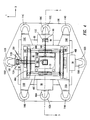
FIG. 1 shows a top view of the present window frame guided stage.
FIG. 2 shows a side view of the window frame guided stage and associated structures.
FIGS. 3A and 3B show enlarged views of portions of the structure of FIG. 2.
FIG. 4 shows a top view of a photolithography apparatus including the present window frame guided stage.
FIG. 5 shows a side view of the photolithography apparatus of FIG. 4.
FIGS. 6A and 6B show a flexure hinge structure as used e.g. in the present window frame guided stage.
FIG. 1 shows a top view of a stage mechanism, in accordance with the present invention. See also copending commonly owned and invented U.S. patent application, Ser. No. 08/221,375 (now U.S. Pat. No. 5,528,118) which is incorporated herein by reference and shows a related method of supporting elements of a stage mechanism so as to isolate reaction forces from the projection lens and other parts of a photolithography apparatus.
The stage 10 is (in plan view) a rectangular structure of a rigid material (e.g., steel, aluminum, or ceramic). Two interferometry mirrors 14A and 14B located on stage 10 interact conventionally with respectively laser beams 16A and 16B. Conventionally, laser beams 16A are two pairs of laser beams and laser beams 16B are one pair of laser beam, for three independent distance measurements. The underside of stage 10 defines a relieved portion 22 (indicated by a dotted line, not being visible in the plane of the drawing). A reticle 24 is located on stage 10 and held by conventional reticle vacuum groove 26 formed in the upper surface of chuck plate 28. Stage 10 also defines a central aperture 30 (passage) below the location of reticle 24. Central aperture 30 allows the light (or other) beam which penetrates through reticle 24 to enter the underlying projection lens, as described further below. (It is to be understood that the reticle 24 itself is not a part of the stage mechanism.) Moreover if the present stage mechanism is to be used for other than a reticle stage, i.e. for supporting a wafer, aperture 30 is not needed.
In an alternative air bearing/vacuum structure, the vacuum portion is physically separated from and adjacent to the air bearing portion. It is to be understood that the vacuum and compressed air are provided externally via tubing in a conventional cable bundle and internal tubing distribution system (not shown in the drawings for simplicity). In operation stage 10 thereby floats on the air bearings 36A, 36B, 36C approximately 1 to 3 micrometers above the flat top surface of base structure 32. It is to be understood that other types of bearings (e.g. air bearing/magnetic combination type) may be used alternatively.
The window frame guide structure moves in the X axis (to the left and right in FIG. 1) supported on horizontal surfaces of fixed guides 46A and 46B, and supported on vertical surfaces of fixed guides 64A, 64B. (It is to be understood that each pair of fixed guides 46A, 64A and 46B, 64B could be e.g. a single L-shaped fixed guide, or other configurations of fixed guides may be used.) Mounted on window frame guide member 40A are two air bearings 50A and 50B that cause the member 40A to ride on its supporting fixed guide member 46A. Similarly air bearings 52A and 52B are mounted on the member 40B, allowing member 40B to ride on its supporting fixed guide member 46B. Air bearings 50A, 50B, 52A, 52B are similar to air bearings 36A, etc.
The window frame guide is driven along the X axis on fixed guides 46A and 46B, 64A and 64B by a conventional linear motor, which includes a coil 60A which is mounted on window frame guide member 40A. Motor coil 60A moves in a magnetic track 62A which is located in (or along) fixed guide 64A. Similarly, motor coil 60B which is mounted on window frame guide member 40B moves in magnetic track 62B which is located in fixed guide 64B. The motor coil and track combinations are part no. LM-310 from Trilogy Company of Webster, Tex. These motors are also called “linear commutator motors”. The tracks 62A, 62B are each a number of permanent magnets fastened together. The electric wires which connect to the motor coils are not shown but are conventional. Other types of linear motors may be substituted. It is to be understood that the locations of the motor coils and magnetic tracks for each motor could be reversed, so that for instance the magnetic tracks are located on stage 10 and the corresponding motor coils on the window frame guide members, at a penalty of reduced performance.
Similarly, stage 10 moves along the Y axis in FIG. 1 by means of motor coils 68A and 68B mounted respectively on the left and right edges of stage 10. Motor coil 68A moves in magnetic track 70A mounted in window frame guide member 40C. Motor coil 68B moves in magnetic track 70B mounted in window frame guide member 40D.
Also shown in FIG. 1 are air bearings 72A, 72B and 72C. Air bearing 72A is located on window frame guide member 40A and minimizes friction between window frame guide member 40A and its fixed guide 64A. Similarly two air bearings 72B and 72C on window frame guide member 40B minimize its friction with the fixed guide 64B. The use of a single air bearing 72A at one end and two opposing air bearings 72B and 72C at the other end allows a certain amount of yaw (rotation in the X-Y plane about the Z-axis) as well as limited motion along the Z-axis. In this case, typically air bearing 72A is gimbal mounted, or gimbal mounted with the gimbal located on a flexure so as to allow a limited amount of misalignment between the member 40A and fixed guide 64A.
The use of the air bearing 72 A opposing bearings 72B and 72C provides a loading effect to keep the window frame guide in its proper relationship to fixed guides 64A, 64B. Similarly, an air bearing 76A loads opposing air bearings 76B and 76C, all mounted on side surfaces of the stage 10, in maintaining the proper location of stage 10 relative to the opposing window frame guide members 40B and 40D. Again, in this case one air bearing such as 76A is gimbal mounted to provide a limited amount of misalignment, or gimbal mounted with the gimbal on a flexure (spring). Air bearings 72A, 72B, 72C and 76A, 76B, and 76C are conventional air bearings.
The outer structure 80 in FIG. 1 is the base support structure for the fixed guides 46A, 46B, 64A, 64B and the window frame guide members 40A, . . . , 40D of the stage mechanism, but does not support stage base structure 32. Thus the underlying support is partitioned so the reaction force on base support structure 80 does not couple into the stage base structure 32. Base support structure 80 is supported by its own support pillars or other conventional support elements (not shown in this drawing) to the ground, i.e. the surface of the earth or the floor of a building. An example of a suitable support structure is disclosed in above-referenced U.S. Pat. No. 5,528,118, at FIGS. 1, 1B, 1C. This independent support structure for this portion of stage mechanism provides the above-described advantage of transmitting the reaction forces of the reticle stage mechanism drive motors away from the frame supporting the other elements of the photolithography apparatus, especially away from the optical elements including the projection lens and from the wafer stage, thereby minimizing vibration forces on the projection lens due to reticle stage movement. This is further described below.
The drive forces for the stage mechanism are provided as close as possible through the stage mechanism center of gravity. As can be understood, the center of gravity of the stage mechanism moves with the stage 10. Thus the stage 10 and the window frame guide combine to define a joint center of gravity. A first differential drive control (not shown) for motor coils 60A, 60B takes into account the location of the window frame guide to control the force exerted by each motor coil 60A, 60B to keep the effective force applied at the center of gravity. A second conventional differential drive control (not shown) for motor coils 68A, 68B takes into account the location of stage 10 to control the force exerted by each motor coil 68A, 68B to keep the effective force applied at the center of gravity. It is to be understood that since stage 10 has a substantial range of movement, that the differential drive for the motor coils 60A, 60B has a wide differential swing. In contrast, the window frame guide has no center gravity change, hence the differential drive for the motor coils 68A, 68B has a much lesser differential swing, providing a trim effect. Advantageously, use of the window frame guide maintains the reaction forces generated by movement of the reticle stage mechanism in a single plane, thus making easier to isolate these forces from other parts of the photolithography apparatus.
FIG. 2 shows a cross-sectional view through line 2—2 of FIG. 1. The structures shown in FIG. 2 which are also in FIG. 1 have identical reference numbers and are not described herein. Also shown in FIG. 2 is the illuminator 90 which is a conventional element shown here without detail, and omitted from FIG. 1 for clarity. Also shown without detail in FIG. 2 is the upper portion of the projection lens (barrel) 92. It is to be understood that the lower portion of the projection lens and other elements of the photolithography apparatus are not shown in FIG. 2, but are illustrated and described below.
The supporting structure 94 for the projection lens 92 is also shown in FIG. 2. As can be seen, structure 94 is separated at all points by a slight gap 96 from the base support structure 80 for the reticle stage mechanism. This gap 96 isolates vibrations caused by movement of the reticle stage mechanism from the projection lens 92 and its support 94. As shown in FIG. 2, stage 10 is not in this embodiment a flat structure but defines the underside relieved portion 22 to accommodate the upper portion of lens 92. Magnetic track 70A is mounted on top of the window frame guide 40B and similarly magnetic track 70B is mounted on top of the opposite window frame guide member 40D.
FIGS. 3A and 3B are enlarged views of portions of FIG. 2, with identical reference numbers; FIG. 3A is the left side of FIG. 2 and FIG. 3B is the right side of FIG. 2. Shown in FIG. 3A is the spring mounting 78 for air bearing 76A. Air bearing 78A being spring mounted to a side surface of stage 10, this allows a certain amount of yaw (rotation in the X-Y plane about the Z-axis) as well as limited motion along the Z-axis. A gimbal mounting may be used in place of or in addition to the spring 78. The spring or gimbal mounting thereby allows for a limited amount of misalignment between stage 10 and members 40C, 40D (not shown in FIG. 3A).
FIG. 4 is a top view of a photolithography apparatus including the stage mechanism of FIGS. 1 and 2 and further including, in addition to the elements shown in FIG. 1, the supporting base structure 100 which supports the photolithography apparatus including frame 94 except for the reticle stage mechanism. (Not all the structures shown in FIG. 1 are labelled in FIG. 4, for simplicity.) Base structure 100 supports four vertical support pillars 102A, 102B, 102C and 102D connected to structure 94 by respectively bracket structures 106A, 106B, 106C and 106D. It is to be appreciated that the size of the base structure 100 is fairly large, i.e. approximately 3 meters top to bottom in one embodiment. Each pillar 102A, 102B, 102C, 102D includes an internal conventional servo mechanism (not shown) for leveling purposes. Also shown in FIG. 4 are the supports 108 and 110 for respectively laser interferometer units (beam splitter etc.) 112A, 112B, 112C. FIG. 4 will be further understood with reference to FIG. 5 which shows a view of FIG. 4 through cross-sectional line 5—5 of FIG. 4.
In FIGS. 4 and 5 the full extent of the supporting structure 94 can be seen along with its support pillars 102A, 102C which rest on the base structure 100 which is in contact with the ground via a conventional foundation (not shown). The independent support structure for the reticle stage base support structure 80 is shown, in FIG. 4 only (for clarity) and similarly includes a set of four pillars 114A, 114B, 114C, 114D with associated bracket structures 116A, 116B, 116C, 116D, with the pillars thereby extending from the level of base support structure 80 down to the base structure 100.
The lower portion of FIG. 5 shows the wafer stage 120 and associated support structures 122, 124. The elements of wafer stage 120 conventionally include (not labelled in the drawing) a base, the stage itself, fixed stage guides located on the base, magnetic tracks located on the fixed stage guides, and motor coils fitting in the magnetic tracks and connected to the stage itself. Laser beams from laser 124 mounted on support 126 locate lens 92 and the stage itself by interferometry.
FIG. 6A shows detail of one of the window frame guide hinged flexure structures, e.g. 44C, in a top view (corresponding to FIG. 1). Each of hinges 44A, 44B, 44C and 44D is identical. These flexure hinges have the advantage over a mechanical-type hinge of not needing lubrication, not exhibiting histeresis (as long as the flexure is not bent beyond its mechanical tolerance) and not having any mechanical “slop”, as well as being inexpensive to fabricate.
Each individual flexure is e.g. ¼ hard 302 stainless steel approximately 20 mils (0.02 inch) thick and can sustain a maximum bend of 0.5 degree. The width of each flexure is not critical; a typical width is 0.5 inch. Two, three or four flexures are used at each hinge 44A, 44B, 44C and 44D in FIG. 1. The number of flexures used at each hinge is essentially determined by the amount of space available, i.e., the height of the window frame guide members. The four individual flexures 130A, 130B, 130C, 130D shown in FIG. 6A (and also in a 90° rotated view in FIG. 6B) are each attached by clamps 136A, 136B, 136C, 136D to adjacent frame members ( members 40B and 40D in FIGS. 6A and 6B) by conventional screws which pass through holes in the individual flexures 130A, 130B, 130C, 130D and through the clamps and are secured in corresponding threaded holes in frame members 40B and 40D.
Note that the frame members 40B, 40D of FIGS. 6A and 6B differ somewhat from those of FIG. 1 in terms of the angular (triangular) structures at the ends of frame members 40B, 40D and to which the metal flexures 130A, 130B, 130C, 130D are mounted. In the embodiment of FIG. 1, these angular structures are dispensed with, although their presence makes screw mounting of the flexures easier.
In an alternate embodiment, the window frame guide is not hinged but is a rigid structure. To accommodate this rigidity and prevent binding, one of bearings 72C or 72B is eliminated, and the remaining bearing moved to the center of member 40B, mounted on a gimbal with no spring. The other bearings (except those mounted on stage 10) are also gimballed.
This disclosure is illustrative and not limiting; further modifications will be apparent to one skilled in the art in light of this disclosure and are intended to fall within the scope of the appended claims.
Claims (33)
1. An exposure apparatus which exposes a pattern of a mask onto an object, comprising:
a main frame;
an exposure device that exposes the pattern onto the object, the exposure device disposed between the mask and the object, and supported by the main frame;
a stage that is movably supported by the main frame;
a reaction frame that is dynamically isolated from the main frame;
a first driver that moves the stage, at least part of the first driver being connected to the reaction frame such that a first reaction force caused by a driving of the first driver is transferred to the reaction frame; and
a second driver that moves the stage, a moving distance of the stage by the second driver being shorter than a moving distance of the stage by the first driver, and at least part of the second driver being connected to the reaction frame such that a second reaction force caused driving of the second driver is transferred to the reaction frame.
2. An exposure apparatus according to claim 1 , wherein the stage holds the mask.
3. An exposure apparatus according to claim 1 , wherein the first driver comprises a linear motor.
4. An exposure apparatus according to claim 3 , wherein the second driver comprises a linear motor.
5. An exposure apparatus according to claim 1 , wherein the second driver comprises a linear motor.
6. An exposure apparatus according to claim 1 , wherein the first driver moves the stage in a first direction and the second driver moves the stage in a second direction that is different from the first direction.
7. An exposure apparatus according to claim 1 , wherein the stage is made of ceramic or steel.
8. An exposure apparatus according to claim 1 , wherein the reaction frame is supported on a foundation.
9. An exposure apparatus according to claim 8 , wherein the foundation is a floor.
10. An exposure apparatus according to claim 1 , wherein a part of the reaction frame is higher than the main frame.
11. An exposure apparatus according to claim 1 , wherein a part of the reaction frame is higher than the object.
12. An exposure apparatus according to claim 1 , wherein the reaction frame comprises a portion that does not receive a weight of the stage.
13. An exposure apparatus according to claim 1 , wherein the first driver comprises a first magnet member and a first coil member, and the second driver comprises a second magnet member and a second coil member.
14. An exposure apparatus which exposes a pattern of a mask onto an object, comprising:
a main frame;
exposure means for exposing the pattern onto the object, the exposure means being supported by the main frame;
a stage that is movably supported by the main frame;
a reaction frame that is dynamically isolated from the main frame;
first drive means for moving the stage, the first drive means being connected to the reaction frame such that a first reaction force caused by a driving of the first drive means is transferred to the reaction frame; and
second drive means for moving the stage, a moving distance of the stage by the second drive means being shorter than a moving distance of the stage by the first drive means, and the second drive means being connected to the reaction frame such that a second reaction force caused by a driving of the second drive means is transferred to the reaction frame.
15. An exposure method that exposes a pattern of a mask onto an object, comprising the steps of:
movably supporting a stage by a main frame;
supporting a projection system that projects the pattern onto the object by the main frame;
moving the stage by a first driver
moving the stage by a second driver, a moving distance of the stage by the second driver being shorter than a moving distance of the stage by the first driver; and
transferring a reaction force caused by the movement of the stage to a reaction frame that is isolated from the main frame and connected to the first driver and the second driver.
16. An exposure method according to claim 15 , wherein the stage holds the mask.
17. An exposure method according to claim 15 , wherein the first driver comprises a linear motor.
18. An exposure method according to claim 17 , wherein the second driver comprises a linear motor.
19. An exposure method according to claim 15 , wherein the second driver comprises a linear motor.
20. An exposure method according to claim 15 , wherein the first driver moves the stage in a first direction, and the second driver moves the stage in a second direction that is different from the first direction.
21. An exposure method according to claim 15 , wherein the stage is made of ceramic or steel.
22. An exposure method according to claim 15 , wherein the reaction frame is supported on a foundation.
23. An exposure method according to claim 22 , wherein the foundation is a floor.
24. An exposure method according to claim 15 , wherein a part of the reaction frame is higher than the main frame.
25. An exposure method according to claim 15 , wherein a part of the reaction frame is higher than the object.
26. An exposure method according to claim 15 , wherein the reaction frame comprises a portion that does not receive a weight of the stage.
27. An exposure method according to claim 15 , wherein the first driver comprises a first magnet member and a first coil member, and the second driver comprises a second magnet member and a second coil member.
28. An exposure apparatus which exposes a pattern of a mask onto an object, comprising:
a main frame;
an exposure device that exposes the pattern onto the object, the exposure device disposed between the mask and the object, and supported by the main frame;
a mask stage that is movably supported by the main frame, the mask stage retaining the mask;
a reaction frame that is dynamically isolated from the main frame, a part of the reaction frame being higher than the object;
a first driver that moves the stage, at least part of the first driver being connected to the reaction frame such that a first reaction force caused by a driving of the first driver is transferred to the reaction frame; and
a second driver that moves the stage, a moving distance of the stage by the second driver being shorter than a moving distance of the stage by the first driver, and at least part of the second driver being connected to the reaction frame such that a second reaction force caused by a ddriving of the second driver is transferred to the reaction frame.
29. An exposure apparatus according to claim 28 , further comprising:
a first interferometer system that detects a position of the mask stage in a first direction; and
a second interferometer system that detects the position of the mask stage in a second direction different from the first direction.
30. An exposure apparatus according to claim 29 , wherein the part of the reaction frame is higher than the main frame.
31. An exposure method that exposes a pattern of a mask onto an object, comprising the steps of:
movably supportion a mask stage by a main frame, the mask stage retaining the mask;
supporting a projection system that projects the pattern onto the object by the main frame;
moving the mask stage by a first driver;
moving the mask stage by a second driver, a moving distance of the stage by the second driver being shorter than a moving distance of the stage by the first driver; and
transferring a reaction force caused by the movement of the stage to a reaction frame that is isolated from the main frame and connected to the first driver and the second driver, a part of the reaction frame being higher than the object.
32. An exposure method according to claim 31 , further comprising:
detecting a position of the mask stage in a first direction by a first interferometer system; and
detecting the position of the mask stage in a second direction different from the first direction by a second interferometer system.
33. An exposure method according to claim 32 , wherein the part of the reaction frame is higher than the main frame.
Priority Applications (2)
| Application Number | Priority Date | Filing Date | Title |
|---|---|---|---|
| US09/964,550 US6683433B2 (en) | 1995-04-04 | 2001-09-28 | Exposure apparatus and method utilizing isolated reaction frame |
| US10/611,260 US6747732B1 (en) | 1995-04-04 | 2003-07-02 | Method of making exposure apparatus with dynamically isolated reaction frame |
Applications Claiming Priority (4)
| Application Number | Priority Date | Filing Date | Title |
|---|---|---|---|
| US08/416,558 US5874820A (en) | 1995-04-04 | 1995-04-04 | Window frame-guided stage mechanism |
| US09/192,153 US6246202B1 (en) | 1995-04-04 | 1998-11-12 | Method of making exposure apparatus with dynamically isolated reaction frame |
| US09/836,273 US6316901B2 (en) | 1995-04-04 | 2001-04-18 | Exposure apparatus and method utilizing isolated reaction frame |
| US09/964,550 US6683433B2 (en) | 1995-04-04 | 2001-09-28 | Exposure apparatus and method utilizing isolated reaction frame |
Related Parent Applications (1)
| Application Number | Title | Priority Date | Filing Date |
|---|---|---|---|
| US09/836,273 Division US6316901B2 (en) | 1995-04-04 | 2001-04-18 | Exposure apparatus and method utilizing isolated reaction frame |
Related Child Applications (1)
| Application Number | Title | Priority Date | Filing Date |
|---|---|---|---|
| US10/611,260 Division US6747732B1 (en) | 1995-04-04 | 2003-07-02 | Method of making exposure apparatus with dynamically isolated reaction frame |
Publications (2)
| Publication Number | Publication Date |
|---|---|
| US20020017889A1 US20020017889A1 (en) | 2002-02-14 |
| US6683433B2 true US6683433B2 (en) | 2004-01-27 |
Family
ID=23650430
Family Applications (11)
| Application Number | Title | Priority Date | Filing Date |
|---|---|---|---|
| US08/416,558 Expired - Lifetime US5874820A (en) | 1994-04-01 | 1995-04-04 | Window frame-guided stage mechanism |
| US09/192,153 Expired - Lifetime US6246202B1 (en) | 1994-04-01 | 1998-11-12 | Method of making exposure apparatus with dynamically isolated reaction frame |
| US09/317,847 Expired - Lifetime US6087797A (en) | 1995-04-04 | 1999-05-25 | Exposure method, and method of making exposure apparatus having dynamically isolated reaction frame |
| US09/318,623 Expired - Lifetime US6188195B1 (en) | 1995-04-04 | 1999-05-26 | Exposure method, and method of making exposure apparatus having dynamically isolated support structure |
| US09/320,842 Expired - Lifetime US6020710A (en) | 1995-04-04 | 1999-05-26 | Exposure method, and method of making exposure apparatus having dynamically isolated reaction frame |
| US09/318,622 Expired - Lifetime US6150787A (en) | 1995-04-04 | 1999-05-26 | Exposure apparatus having dynamically isolated reaction frame |
| US09/320,703 Expired - Lifetime US6175404B1 (en) | 1995-04-04 | 1999-05-27 | Exposure apparatus having dynamically isolated reaction frame |
| US09/320,706 Expired - Lifetime US6151105A (en) | 1995-04-04 | 1999-05-27 | Exposure apparatus having dynamically isolated support structure |
| US09/836,273 Expired - Lifetime US6316901B2 (en) | 1995-04-04 | 2001-04-18 | Exposure apparatus and method utilizing isolated reaction frame |
| US09/964,550 Expired - Fee Related US6683433B2 (en) | 1995-04-04 | 2001-09-28 | Exposure apparatus and method utilizing isolated reaction frame |
| US10/611,260 Expired - Fee Related US6747732B1 (en) | 1995-04-04 | 2003-07-02 | Method of making exposure apparatus with dynamically isolated reaction frame |
Family Applications Before (9)
| Application Number | Title | Priority Date | Filing Date |
|---|---|---|---|
| US08/416,558 Expired - Lifetime US5874820A (en) | 1994-04-01 | 1995-04-04 | Window frame-guided stage mechanism |
| US09/192,153 Expired - Lifetime US6246202B1 (en) | 1994-04-01 | 1998-11-12 | Method of making exposure apparatus with dynamically isolated reaction frame |
| US09/317,847 Expired - Lifetime US6087797A (en) | 1995-04-04 | 1999-05-25 | Exposure method, and method of making exposure apparatus having dynamically isolated reaction frame |
| US09/318,623 Expired - Lifetime US6188195B1 (en) | 1995-04-04 | 1999-05-26 | Exposure method, and method of making exposure apparatus having dynamically isolated support structure |
| US09/320,842 Expired - Lifetime US6020710A (en) | 1995-04-04 | 1999-05-26 | Exposure method, and method of making exposure apparatus having dynamically isolated reaction frame |
| US09/318,622 Expired - Lifetime US6150787A (en) | 1995-04-04 | 1999-05-26 | Exposure apparatus having dynamically isolated reaction frame |
| US09/320,703 Expired - Lifetime US6175404B1 (en) | 1995-04-04 | 1999-05-27 | Exposure apparatus having dynamically isolated reaction frame |
| US09/320,706 Expired - Lifetime US6151105A (en) | 1995-04-04 | 1999-05-27 | Exposure apparatus having dynamically isolated support structure |
| US09/836,273 Expired - Lifetime US6316901B2 (en) | 1995-04-04 | 2001-04-18 | Exposure apparatus and method utilizing isolated reaction frame |
Family Applications After (1)
| Application Number | Title | Priority Date | Filing Date |
|---|---|---|---|
| US10/611,260 Expired - Fee Related US6747732B1 (en) | 1995-04-04 | 2003-07-02 | Method of making exposure apparatus with dynamically isolated reaction frame |
Country Status (3)
| Country | Link |
|---|---|
| US (11) | US5874820A (en) |
| JP (3) | JPH08330224A (en) |
| KR (6) | KR100300220B1 (en) |
Cited By (15)
| Publication number | Priority date | Publication date | Assignee | Title |
|---|---|---|---|---|
| US20050029981A1 (en) * | 2003-08-08 | 2005-02-10 | Asml Holding N.V. | Foam core chuck for the scanning stage of a lithography system |
| US20060098184A1 (en) * | 2003-06-04 | 2006-05-11 | Nikon Corporation | Stage apparatus, fixation method, exposure apparatus, exposure method, and device-producing method |
| US20060132740A1 (en) * | 2003-06-19 | 2006-06-22 | Nikon Corporation | Exposure apparatus, and device manufacturing method |
| US20060274293A1 (en) * | 2003-02-26 | 2006-12-07 | Nikon Corporation | Exposure apparatus, exposure method, and method for producing device |
| US20070064210A1 (en) * | 2003-05-23 | 2007-03-22 | Nikon Corporation | Exposure apparatus and method for producing device |
| US20070132975A1 (en) * | 2003-04-11 | 2007-06-14 | Nikon Corporation | Cleanup method for optics in immersion lithography |
| US20070182945A1 (en) * | 2004-07-12 | 2007-08-09 | Makoto Shibuta | Exposure apparatus and device manufacturing method |
| US20070228295A1 (en) * | 2004-12-23 | 2007-10-04 | Asml Netherlands B.V. | Lithographic Apparatus, Support, Device Manufacturing Method, and a Method of Supporting |
| US20070242247A1 (en) * | 2004-06-09 | 2007-10-18 | Kenichi Shiraishi | Exposure apparatus and device manufacturing method |
| US20070247607A1 (en) * | 2004-02-02 | 2007-10-25 | Nikon Corporation | Stage drive method and stage unit, exposure apparatus, and device manufacturing method |
| US20070247602A1 (en) * | 2003-04-11 | 2007-10-25 | Nikon Corporation | Apparatus and method for maintaining immersion fluid in the gap under the projection lens during wafer exchange in an immersion lithography machine |
| US20070263193A1 (en) * | 2003-07-09 | 2007-11-15 | Nikon Corporation | Exposure apparatus and method for manufacturing device |
| US7852034B2 (en) | 2004-04-09 | 2010-12-14 | Nikon Corporation | Drive method of moving body, stage unit, and exposure apparatus |
| US8451424B2 (en) | 2003-07-28 | 2013-05-28 | Nikon Corporation | Exposure apparatus, method for producing device, and method for controlling exposure apparatus |
| US20140203187A1 (en) * | 2008-08-18 | 2014-07-24 | Jerry Peijster | Charged Particle Beam Lithography System and Target Positioning Device |
Families Citing this family (242)
| Publication number | Priority date | Publication date | Assignee | Title |
|---|---|---|---|---|
| US5874820A (en) * | 1995-04-04 | 1999-02-23 | Nikon Corporation | Window frame-guided stage mechanism |
| US6989647B1 (en) * | 1994-04-01 | 2006-01-24 | Nikon Corporation | Positioning device having dynamically isolated frame, and lithographic device provided with such a positioning device |
| US5528118A (en) | 1994-04-01 | 1996-06-18 | Nikon Precision, Inc. | Guideless stage with isolated reaction stage |
| US7365513B1 (en) | 1994-04-01 | 2008-04-29 | Nikon Corporation | Positioning device having dynamically isolated frame, and lithographic device provided with such a positioning device |
| JP3363662B2 (en) * | 1994-05-19 | 2003-01-08 | キヤノン株式会社 | Scanning stage apparatus and exposure apparatus using the same |
| US6721034B1 (en) | 1994-06-16 | 2004-04-13 | Nikon Corporation | Stage unit, drive table, and scanning exposure apparatus using the same |
| US5850280A (en) * | 1994-06-16 | 1998-12-15 | Nikon Corporation | Stage unit, drive table, and scanning exposure and apparatus using same |
| US6008500A (en) * | 1995-04-04 | 1999-12-28 | Nikon Corporation | Exposure apparatus having dynamically isolated reaction frame |
| US6392741B1 (en) * | 1995-09-05 | 2002-05-21 | Nikon Corporation | Projection exposure apparatus having active vibration isolator and method of controlling vibration by the active vibration isolator |
| US6522386B1 (en) | 1997-07-24 | 2003-02-18 | Nikon Corporation | Exposure apparatus having projection optical system with aberration correction element |
| WO1999025011A1 (en) | 1997-11-12 | 1999-05-20 | Nikon Corporation | Projection exposure apparatus |
| AU1260099A (en) | 1997-11-25 | 1999-06-15 | Nikon Corporation | Projection exposure system |
| JP3526202B2 (en) * | 1998-02-03 | 2004-05-10 | キヤノン株式会社 | Stage apparatus, exposure apparatus using the same, and device manufacturing method |
| AU2186099A (en) | 1998-02-09 | 1999-08-23 | Nikon Corporation | Apparatus for supporting base plate, apparatus and method for transferring base plate, method of replacing base plate, and exposure apparatus and method of manufacturing the same |
| US6260282B1 (en) * | 1998-03-27 | 2001-07-17 | Nikon Corporation | Stage control with reduced synchronization error and settling time |
| JPH11287880A (en) * | 1998-04-01 | 1999-10-19 | Canon Inc | Stage device, aligner using the device and device production method |
| JP3554186B2 (en) * | 1998-04-08 | 2004-08-18 | キヤノン株式会社 | Exposure apparatus, device manufacturing method, and reaction force receiving method |
| JP4362975B2 (en) | 1998-04-10 | 2009-11-11 | 株式会社ニコン | Linear motor coil, coil, linear motor, electric motor, linear motor manufacturing method, electric motor manufacturing method, stage apparatus, exposure apparatus |
| WO1999066542A1 (en) * | 1998-06-17 | 1999-12-23 | Nikon Corporation | Exposure method and exposure apparatus |
| TWI242113B (en) * | 1998-07-17 | 2005-10-21 | Asml Netherlands Bv | Positioning device and lithographic projection apparatus comprising such a device |
| KR20010053600A (en) | 1998-07-22 | 2001-06-25 | 오노 시게오 | Mark detecting method, exposure method, device manufacturing method, mark detector, exposure apparatus, and device |
| US6252234B1 (en) * | 1998-08-14 | 2001-06-26 | Nikon Corporation | Reaction force isolation system for a planar motor |
| JP2001068396A (en) * | 1999-08-26 | 2001-03-16 | Canon Inc | Stage control apparatus |
| JP3616543B2 (en) | 1999-09-10 | 2005-02-02 | 日本電気株式会社 | XY stage |
| US6549277B1 (en) | 1999-09-28 | 2003-04-15 | Nikon Corporation | Illuminance meter, illuminance measuring method and exposure apparatus |
| US6324933B1 (en) | 1999-10-06 | 2001-12-04 | Agere Systems Guardian Corp. | Planar movable stage mechanism |
| EP1107067B1 (en) * | 1999-12-01 | 2006-12-27 | ASML Netherlands B.V. | Positioning apparatus and lithographic apparatus comprising the same |
| DE60032568T2 (en) | 1999-12-01 | 2007-10-04 | Asml Netherlands B.V. | Positioning apparatus and lithographic apparatus provided therewith |
| US6791661B2 (en) | 1999-12-09 | 2004-09-14 | Nikon Corporation | Gas replacement method and apparatus, and exposure method and apparatus |
| EP1248288A1 (en) | 1999-12-16 | 2002-10-09 | Nikon Corporation | Exposure method and exposure apparatus |
| US6836093B1 (en) * | 1999-12-21 | 2004-12-28 | Nikon Corporation | Exposure method and apparatus |
| TW546551B (en) * | 1999-12-21 | 2003-08-11 | Asml Netherlands Bv | Balanced positioning system for use in lithographic apparatus |
| US6271606B1 (en) * | 1999-12-23 | 2001-08-07 | Nikon Corporation | Driving motors attached to a stage that are magnetically coupled through a chamber |
| US6555829B1 (en) | 2000-01-10 | 2003-04-29 | Applied Materials, Inc. | High precision flexure stage |
| JP2001209188A (en) | 2000-01-27 | 2001-08-03 | Nikon Corp | Scanning type aligner, method for scanning exposure and mask |
| TW495836B (en) | 2000-02-02 | 2002-07-21 | Nikon Corp | Scanning exposure method and device |
| US6307619B1 (en) | 2000-03-23 | 2001-10-23 | Silicon Valley Group, Inc. | Scanning framing blade apparatus |
| JP2001297960A (en) | 2000-04-11 | 2001-10-26 | Nikon Corp | Stage device and projection aligner |
| US6405659B1 (en) | 2000-05-01 | 2002-06-18 | Nikon Corporation | Monolithic stage |
| KR100592576B1 (en) * | 2000-06-02 | 2006-06-26 | 에이에스엠엘 네델란즈 비.브이. | Lithographic projection apparatus, supporting assembly and device manufacturing method |
| US6496060B2 (en) | 2000-06-15 | 2002-12-17 | Nikon Corporation | Hybridized, high performance PWM amplifier |
| JP4474020B2 (en) * | 2000-06-23 | 2010-06-02 | キヤノン株式会社 | Moving apparatus and exposure apparatus |
| WO2002067055A2 (en) * | 2000-10-12 | 2002-08-29 | Board Of Regents, The University Of Texas System | Template for room temperature, low pressure micro- and nano-imprint lithography |
| US6885430B2 (en) * | 2000-11-16 | 2005-04-26 | Nikon Corporation | System and method for resetting a reaction mass assembly of a stage assembly |
| US6958808B2 (en) * | 2000-11-16 | 2005-10-25 | Nikon Corporation | System and method for resetting a reaction mass assembly of a stage assembly |
| US6496248B2 (en) * | 2000-12-15 | 2002-12-17 | Nikon Corporation | Stage device and exposure apparatus and method |
| US6906334B2 (en) | 2000-12-19 | 2005-06-14 | Nikon Corporation | Curved I-core |
| US20020080339A1 (en) * | 2000-12-25 | 2002-06-27 | Nikon Corporation | Stage apparatus, vibration control method and exposure apparatus |
| JP2002252166A (en) * | 2001-02-27 | 2002-09-06 | Canon Inc | Stage device, aligner, device manufacturing method and movement guide method |
| US6490105B2 (en) * | 2001-03-27 | 2002-12-03 | Nikon Precision Inc. | Stage mirror retention system |
| US6678038B2 (en) | 2001-08-03 | 2004-01-13 | Nikon Corporation | Apparatus and methods for detecting tool-induced shift in microlithography apparatus |
| US6648509B2 (en) | 2001-08-15 | 2003-11-18 | Nikon Corporation | Friction-drive stage |
| US6842226B2 (en) * | 2001-09-21 | 2005-01-11 | Nikon Corporation | Flexure supported wafer table |
| US6600547B2 (en) | 2001-09-24 | 2003-07-29 | Nikon Corporation | Sliding seal |
| US6888620B2 (en) * | 2001-11-29 | 2005-05-03 | Nikon Corporation | System and method for holding a device with minimal deformation |
| US20030098965A1 (en) * | 2001-11-29 | 2003-05-29 | Mike Binnard | System and method for supporting a device holder with separate components |
| US7813634B2 (en) | 2005-02-28 | 2010-10-12 | Tessera MEMS Technologies, Inc. | Autofocus camera |
| US6879127B2 (en) | 2002-02-12 | 2005-04-12 | Nikon Corporation | 3-ring magnetic anti-gravity support |
| US6784978B2 (en) * | 2002-03-12 | 2004-08-31 | Asml Holding N.V. | Method, system, and apparatus for management of reaction loads in a lithography system |
| US6809323B2 (en) * | 2002-04-03 | 2004-10-26 | Nikon Corporation | Isolated frame caster |
| JP4211272B2 (en) * | 2002-04-12 | 2009-01-21 | 株式会社ニコン | Exposure apparatus and exposure method |
| US6724000B2 (en) | 2002-05-16 | 2004-04-20 | Nikon Corporation | Reaction frame apparatus and method |
| US6844635B2 (en) * | 2002-05-24 | 2005-01-18 | Dover Instrument Corporation | Reaction force transfer system |
| JP3962669B2 (en) * | 2002-10-08 | 2007-08-22 | キヤノン株式会社 | Moving apparatus, exposure apparatus, and device manufacturing method |
| US20040080730A1 (en) * | 2002-10-29 | 2004-04-29 | Michael Binnard | System and method for clamping a device holder with reduced deformation |
| US10503084B2 (en) | 2002-11-12 | 2019-12-10 | Asml Netherlands B.V. | Lithographic apparatus and device manufacturing method |
| US9482966B2 (en) | 2002-11-12 | 2016-11-01 | Asml Netherlands B.V. | Lithographic apparatus and device manufacturing method |
| US7372541B2 (en) * | 2002-11-12 | 2008-05-13 | Asml Netherlands B.V. | Lithographic apparatus and device manufacturing method |
| KR100588124B1 (en) * | 2002-11-12 | 2006-06-09 | 에이에스엠엘 네델란즈 비.브이. | Lithographic Apparatus and Device Manufacturing Method |
| JP3977324B2 (en) | 2002-11-12 | 2007-09-19 | エーエスエムエル ネザーランズ ビー.ブイ. | Lithographic apparatus |
| WO2004053953A1 (en) * | 2002-12-10 | 2004-06-24 | Nikon Corporation | Exposure apparatus and method for manufacturing device |
| KR101085372B1 (en) * | 2002-12-10 | 2011-11-21 | 가부시키가이샤 니콘 | Exposure apparatus and method for manufacturing device |
| DE10261775A1 (en) | 2002-12-20 | 2004-07-01 | Carl Zeiss Smt Ag | Device for the optical measurement of an imaging system |
| US20040119436A1 (en) * | 2002-12-23 | 2004-06-24 | Michael Binnard | Method and apparatus for reducing countermass stroke with initial velocity |
| US6870600B2 (en) * | 2003-01-13 | 2005-03-22 | Nikon Corporation | Vibration-attenuation devices and methods using pressurized bellows exhibiting substantially zero lateral stiffness |
| US20040160132A1 (en) * | 2003-02-14 | 2004-08-19 | Carter Frederick Michael | System and method to reduce the effect of reactive forces on a stage using a balance mass |
| TWI338323B (en) * | 2003-02-17 | 2011-03-01 | Nikon Corp | Stage device, exposure device and manufacguring method of devices |
| KR101181688B1 (en) | 2003-03-25 | 2012-09-19 | 가부시키가이샤 니콘 | Exposure system and device production method |
| JP4902201B2 (en) | 2003-04-07 | 2012-03-21 | 株式会社ニコン | Exposure apparatus, exposure method, and device manufacturing method |
| EP3226073A3 (en) | 2003-04-09 | 2017-10-11 | Nikon Corporation | Exposure method and apparatus, and method for fabricating device |
| EP2921905B1 (en) | 2003-04-10 | 2017-12-27 | Nikon Corporation | Run-off path to collect liquid for an immersion lithography apparatus |
| JP4650413B2 (en) * | 2003-04-10 | 2011-03-16 | 株式会社ニコン | Environmental system including a transfer area for an immersion lithography apparatus |
| SG2012050829A (en) * | 2003-04-10 | 2015-07-30 | Nippon Kogaku Kk | Environmental system including vacuum scavange for an immersion lithography apparatus |
| TWI295414B (en) | 2003-05-13 | 2008-04-01 | Asml Netherlands Bv | Lithographic apparatus and device manufacturing method |
| WO2004102646A1 (en) * | 2003-05-15 | 2004-11-25 | Nikon Corporation | Exposure apparatus and method for manufacturing device |
| TWI470671B (en) | 2003-05-23 | 2015-01-21 | 尼康股份有限公司 | Exposure method and exposure apparatus, and device manufacturing method |
| KR20060009957A (en) * | 2003-05-27 | 2006-02-01 | 가부시키가이샤 니콘 | Exposure apparatus and device-producing method |
| KR101728664B1 (en) | 2003-05-28 | 2017-05-02 | 가부시키가이샤 니콘 | Exposure method, exposure device, and device manufacturing method |
| US7213963B2 (en) | 2003-06-09 | 2007-05-08 | Asml Netherlands B.V. | Lithographic apparatus and device manufacturing method |
| KR101940892B1 (en) * | 2003-06-13 | 2019-01-21 | 가부시키가이샤 니콘 | Exposure method, substrate stage, exposure apparatus and method for manufacturing device |
| EP2853943B1 (en) | 2003-07-08 | 2016-11-16 | Nikon Corporation | Wafer table for immersion lithography |
| CN102944981A (en) * | 2003-07-09 | 2013-02-27 | 株式会社尼康 | Exposure apparatus, and device fabricating method |
| WO2005006417A1 (en) * | 2003-07-09 | 2005-01-20 | Nikon Corporation | Exposure apparatus and method for manufacturing device |
| EP2264532B1 (en) | 2003-07-09 | 2012-10-31 | Nikon Corporation | Exposure apparatus and device manufacturing method |
| EP1503244A1 (en) * | 2003-07-28 | 2005-02-02 | ASML Netherlands B.V. | Lithographic projection apparatus and device manufacturing method |
| KR101613384B1 (en) | 2003-08-21 | 2016-04-18 | 가부시키가이샤 니콘 | Exposure apparatus, exposure method, and device producing method |
| KR101874724B1 (en) | 2003-08-29 | 2018-07-04 | 가부시키가이샤 니콘 | Liquid recovery apparatus, exposure apparatus, exposure method, and device production method |
| SG145780A1 (en) * | 2003-08-29 | 2008-09-29 | Nikon Corp | Exposure apparatus and device fabricating method |
| US20050057102A1 (en) * | 2003-09-11 | 2005-03-17 | Nikon Corporation | Holding member, coolant, cooling method and cooling device, linear motor device, stage device, and exposure apparatus |
| WO2005029559A1 (en) * | 2003-09-19 | 2005-03-31 | Nikon Corporation | Exposure apparatus and device producing method |
| TW201809911A (en) | 2003-09-29 | 2018-03-16 | 尼康股份有限公司 | Exposure apparatus, exposure method, and method for producing device |
| JP2005136364A (en) * | 2003-10-08 | 2005-05-26 | Zao Nikon Co Ltd | Substrate carrying device, exposure device and device manufacturing method |
| KR101319109B1 (en) * | 2003-10-08 | 2013-10-17 | 가부시키가이샤 자오 니콘 | Substrate carrying apparatus, substrate carrying method, exposure apparatus, exposure method, and method for producing device |
| TWI598934B (en) | 2003-10-09 | 2017-09-11 | Nippon Kogaku Kk | Exposure apparatus, exposure method, and device manufacturing method |
| DE602004030365D1 (en) | 2003-10-22 | 2011-01-13 | Nippon Kogaku Kk | EXPOSURE DEVICE, EXPOSURE METHOD AND METHOD FOR MANUFACTURING COMPONENTS |
| TWI609409B (en) | 2003-10-28 | 2017-12-21 | 尼康股份有限公司 | Optical illumination device, exposure device, exposure method and device manufacturing method |
| WO2005041276A1 (en) * | 2003-10-28 | 2005-05-06 | Nikon Corporation | Exposure apparatus, exposure method, and device producing method |
| WO2005043607A1 (en) | 2003-10-31 | 2005-05-12 | Nikon Corporation | Exposure apparatus and device producing method |
| TWI361450B (en) | 2003-10-31 | 2012-04-01 | Nikon Corp | Platen, stage device, exposure device and exposure method |
| JP2005159322A (en) * | 2003-10-31 | 2005-06-16 | Nikon Corp | Surface plate, stage apparatus, exposure device and exposing method |
| TWI387855B (en) * | 2003-11-13 | 2013-03-01 | 尼康股份有限公司 | A variable slit device, a lighting device, an exposure device, an exposure method, and an element manufacturing method |
| JPWO2005048325A1 (en) * | 2003-11-17 | 2007-11-29 | 株式会社ニコン | Stage driving method, stage apparatus, and exposure apparatus |
| TWI512335B (en) | 2003-11-20 | 2015-12-11 | 尼康股份有限公司 | Light beam converter, optical illuminating apparatus, exposure device, and exposure method |
| TWI440981B (en) | 2003-12-03 | 2014-06-11 | 尼康股份有限公司 | Exposure apparatus, exposure method, and device manufacturing method |
| US20050128449A1 (en) * | 2003-12-12 | 2005-06-16 | Nikon Corporation, A Japanese Corporation | Utilities transfer system in a lithography system |
| KR101941351B1 (en) * | 2003-12-15 | 2019-01-22 | 가부시키가이샤 니콘 | Stage system, exposure apparatus and exposure method |
| DE602004027162D1 (en) | 2004-01-05 | 2010-06-24 | Nippon Kogaku Kk | EXPOSURE DEVICE, EXPOSURE METHOD AND COMPONENT MANUFACTURING METHOD |
| WO2005069355A1 (en) | 2004-01-15 | 2005-07-28 | Nikon Corporation | Exposure apparatus and device producing method |
| JP4843503B2 (en) * | 2004-01-20 | 2011-12-21 | カール・ツァイス・エスエムティー・ゲーエムベーハー | Microlithographic projection exposure apparatus and measuring apparatus for projection lens |
| US20050162802A1 (en) * | 2004-01-22 | 2005-07-28 | Nikon Research Corporation Of America | Offset gap control for electromagnetic devices |
| WO2005071717A1 (en) * | 2004-01-26 | 2005-08-04 | Nikon Corporation | Exposure apparatus and device producing method |
| US7221433B2 (en) * | 2004-01-28 | 2007-05-22 | Nikon Corporation | Stage assembly including a reaction assembly having a connector assembly |
| EP1713114B1 (en) * | 2004-02-03 | 2018-09-19 | Nikon Corporation | Exposure apparatus and device manufacturing method |
| WO2005076325A1 (en) * | 2004-02-04 | 2005-08-18 | Nikon Corporation | Exposure equipment and method, position control method and device manufacturing method |
| EP3208658B1 (en) | 2004-02-04 | 2018-06-06 | Nikon Corporation | Exposure apparatus, exposure method, and method for producing a device |
| TWI614795B (en) | 2004-02-06 | 2018-02-11 | Nikon Corporation | Optical illumination apparatus, light-exposure apparatus, light-exposure method and device manufacturing method |
| WO2005076323A1 (en) | 2004-02-10 | 2005-08-18 | Nikon Corporation | Aligner, device manufacturing method, maintenance method and aligning method |
| WO2005081291A1 (en) * | 2004-02-19 | 2005-09-01 | Nikon Corporation | Exposure apparatus and method of producing device |
| KR100541740B1 (en) * | 2004-02-19 | 2006-01-11 | 삼성전자주식회사 | Transfer apparatus |
| US20070030467A1 (en) * | 2004-02-19 | 2007-02-08 | Nikon Corporation | Exposure apparatus, exposure method, and device fabricating method |
| JP5076497B2 (en) * | 2004-02-20 | 2012-11-21 | 株式会社ニコン | Exposure apparatus, liquid supply method and recovery method, exposure method, and device manufacturing method |
| US8027813B2 (en) * | 2004-02-20 | 2011-09-27 | Nikon Precision, Inc. | Method and system for reconstructing aberrated image profiles through simulation |
| KR101851511B1 (en) | 2004-03-25 | 2018-04-23 | 가부시키가이샤 니콘 | Exposure apparatus and method for manufacturing device |
| US7034917B2 (en) * | 2004-04-01 | 2006-04-25 | Asml Netherlands B.V. | Lithographic apparatus, device manufacturing method and device manufactured thereby |
| JP4677986B2 (en) | 2004-04-19 | 2011-04-27 | 株式会社ニコン | Nozzle member, exposure method, exposure apparatus, and device manufacturing method |
| US7486381B2 (en) * | 2004-05-21 | 2009-02-03 | Asml Netherlands B.V. | Lithographic apparatus and device manufacturing method |
| WO2005119368A2 (en) | 2004-06-04 | 2005-12-15 | Carl Zeiss Smt Ag | System for measuring the image quality of an optical imaging system |
| EP1768169B9 (en) * | 2004-06-04 | 2013-03-06 | Nikon Corporation | Exposure apparatus, exposure method, and device producing method |
| EP1780786A4 (en) * | 2004-06-07 | 2009-11-25 | Nikon Corp | Stage apparatus, exposure apparatus, and exposure method |
| EP2637061B1 (en) | 2004-06-09 | 2018-07-18 | Nikon Corporation | Exposure apparatus, exposure method and method for producing a device |
| US8717533B2 (en) * | 2004-06-10 | 2014-05-06 | Nikon Corporation | Exposure apparatus, exposure method, and method for producing device |
| WO2005122220A1 (en) | 2004-06-10 | 2005-12-22 | Nikon Corporation | Exposure apparatus, exposure method, and device producing method |
| WO2005122221A1 (en) | 2004-06-10 | 2005-12-22 | Nikon Corporation | Exposure equipment, exposure method and device manufacturing method |
| US8373843B2 (en) * | 2004-06-10 | 2013-02-12 | Nikon Corporation | Exposure apparatus, exposure method, and method for producing device |
| US8508713B2 (en) * | 2004-06-10 | 2013-08-13 | Nikon Corporation | Exposure apparatus, exposure method, and method for producing device |
| US8698998B2 (en) * | 2004-06-21 | 2014-04-15 | Nikon Corporation | Exposure apparatus, method for cleaning member thereof, maintenance method for exposure apparatus, maintenance device, and method for producing device |
| EP3462241A1 (en) | 2004-06-21 | 2019-04-03 | Nikon Corporation | Exposure apparatus, exposure method and method for producing a device |
| JP5119666B2 (en) | 2004-06-21 | 2013-01-16 | 株式会社ニコン | Exposure apparatus, liquid removal method, and device manufacturing method |
| US7292310B2 (en) * | 2004-07-02 | 2007-11-06 | Asml Netherlands B.V. | Lithographic apparatus and a device manufacturing method |
| US7463330B2 (en) | 2004-07-07 | 2008-12-09 | Asml Netherlands B.V. | Lithographic apparatus and device manufacturing method |
| JPWO2006006730A1 (en) * | 2004-07-15 | 2008-05-01 | 株式会社ニコン | Planar motor apparatus, stage apparatus, exposure apparatus, and device manufacturing method |
| EP1783823A4 (en) * | 2004-07-21 | 2009-07-22 | Nikon Corp | Exposure method and method for producing device |
| US7030959B2 (en) * | 2004-07-23 | 2006-04-18 | Nikon Corporation | Extreme ultraviolet reticle protection using gas flow thermophoresis |
| KR101230712B1 (en) | 2004-08-03 | 2013-02-07 | 가부시키가이샤 니콘 | Exposure equipment, exposure method and device manufacturing method |
| TW200615716A (en) * | 2004-08-05 | 2006-05-16 | Nikon Corp | Stage device and exposure device |
| JP2008511138A (en) | 2004-08-18 | 2008-04-10 | ニュー ウエイ マシーン コンポーネント インコーポレイティッド | Moving vacuum chamber stage with air bearing and step pump groove |
| JP4983257B2 (en) * | 2004-08-18 | 2012-07-25 | 株式会社ニコン | Exposure apparatus, device manufacturing method, measuring member, and measuring method |
| ATE535015T1 (en) * | 2004-09-01 | 2011-12-15 | Nikon Corp | SUBSTRATE HOLDER, STAGE DEVICE AND EXPOSURE DEVICE |
| JP2006083883A (en) * | 2004-09-14 | 2006-03-30 | Fujikura Rubber Ltd | Vibration-free base device |
| SG155927A1 (en) * | 2004-09-17 | 2009-10-29 | Nikon Corp | Substrate holding device, exposure apparatus, and device manufacturing method |
| TWI417940B (en) * | 2004-09-17 | 2013-12-01 | 尼康股份有限公司 | Exposure apparatus, exposure method, and device manufacturing method |
| CN101015039B (en) * | 2004-09-17 | 2010-09-01 | 尼康股份有限公司 | Substrate for exposure, exposure method and device manufacturing method |
| JP4071227B2 (en) * | 2004-09-28 | 2008-04-02 | 株式会社新川 | Bonding equipment |
| WO2006038563A1 (en) | 2004-10-01 | 2006-04-13 | Nikon Corporation | Linear motor, stage apparatus and exposure apparatus |
| EP1806771A4 (en) * | 2004-10-08 | 2008-06-18 | Nikon Corp | Exposure device and device manufacturing method |
| WO2006041086A1 (en) * | 2004-10-13 | 2006-04-20 | Nikon Corporation | Exposure device, exposure method, and device manufacturing method |
| JP4665712B2 (en) | 2004-10-26 | 2011-04-06 | 株式会社ニコン | Substrate processing method, exposure apparatus and device manufacturing method |
| EP1816671A4 (en) | 2004-11-11 | 2010-01-13 | Nikon Corp | Exposure method, device manufacturing method, and substrate |
| US20070285634A1 (en) * | 2004-11-19 | 2007-12-13 | Nikon Corporation | Maintenance Method, Exposure Method, Exposure Apparatus, And Method For Producing Device |
| EP1826813A4 (en) | 2004-12-01 | 2009-05-13 | Nikon Corp | Stage device and exposure apparatus |
| US20080106718A1 (en) * | 2004-12-02 | 2008-05-08 | Nikon Corporation | Exposure Apparatus and Device Manufacturing Method |
| TW200632576A (en) * | 2004-12-02 | 2006-09-16 | Nikon Corp | Exposure apparatus, exposure method and manufacturing method of device |
| WO2006062074A1 (en) * | 2004-12-06 | 2006-06-15 | Nikon Corporation | Substrate processing method, exposure method, exposure apparatus, and method for manufacturing device |
| US7397533B2 (en) * | 2004-12-07 | 2008-07-08 | Asml Netherlands B.V. | Lithographic apparatus and device manufacturing method |
| JP4752473B2 (en) * | 2004-12-09 | 2011-08-17 | 株式会社ニコン | Exposure apparatus, exposure method, and device manufacturing method |
| KR101771334B1 (en) | 2004-12-15 | 2017-08-24 | 가부시키가이샤 니콘 | Substrate holding apparatus, exposure apparatus and device manufacturing method |
| EP1830456A1 (en) * | 2004-12-24 | 2007-09-05 | Nikon Corporation | Magnetic guiding apparatus, stage apparatus, exposure apparatus and device manufacturing method |
| US7450217B2 (en) * | 2005-01-12 | 2008-11-11 | Asml Netherlands B.V. | Exposure apparatus, coatings for exposure apparatus, lithographic apparatus, device manufacturing method, and device manufactured thereby |
| KR101208387B1 (en) * | 2005-01-21 | 2012-12-05 | 가부시키가이샤 니콘 | Linear motor, stage apparatus, and exposure apparatus |
| KR101240130B1 (en) | 2005-01-25 | 2013-03-07 | 가부시키가이샤 니콘 | Exposure device, exposure method, and micro device manufacturing method |
| US20070258068A1 (en) * | 2005-02-17 | 2007-11-08 | Hiroto Horikawa | Exposure Apparatus, Exposure Method, and Device Fabricating Method |
| US20060192858A1 (en) * | 2005-02-28 | 2006-08-31 | Calvet Robert J | Oil damping for camera optical assembly |
| US7283210B2 (en) * | 2005-03-22 | 2007-10-16 | Nikon Corporation | Image shift optic for optical system |
| KR101555707B1 (en) | 2005-04-18 | 2015-09-25 | 가부시키가이샤 니콘 | Exposure device exposure method and device manufacturing method |
| EP2527921A3 (en) * | 2005-04-28 | 2017-10-18 | Nikon Corporation | Exposure method and exposure apparatus |
| EP3232270A3 (en) | 2005-05-12 | 2017-12-13 | Nikon Corporation | Projection optical system, exposure apparatus, and exposure method |
| US8693006B2 (en) * | 2005-06-28 | 2014-04-08 | Nikon Corporation | Reflector, optical element, interferometer system, stage device, exposure apparatus, and device fabricating method |
| JP2007012375A (en) * | 2005-06-29 | 2007-01-18 | Toyota Motor Corp | Fuel cell, method of manufacturing electrode catalyst layer, and operation method thereof |
| JP5353005B2 (en) | 2005-07-11 | 2013-11-27 | 株式会社ニコン | Exposure apparatus, exposure method, and device manufacturing method |
| JP5309565B2 (en) * | 2005-08-05 | 2013-10-09 | 株式会社ニコン | Stage apparatus, exposure apparatus, method, exposure method, and device manufacturing method |
| US7580112B2 (en) * | 2005-08-25 | 2009-08-25 | Nikon Corporation | Containment system for immersion fluid in an immersion lithography apparatus |
| DE102005045680A1 (en) * | 2005-09-24 | 2007-04-05 | Edmund Uschkurat | Device for aligning an object along an X-, Y- or Z-axis used e.g. in the pharmaceutical industry comprises a base plate and tables adjustable along the X-axis, Y-axis and the Z-axis |
| US8125610B2 (en) * | 2005-12-02 | 2012-02-28 | ASML Metherlands B.V. | Method for preventing or reducing contamination of an immersion type projection apparatus and an immersion type lithographic apparatus |
| DE102005061215B4 (en) * | 2005-12-21 | 2019-06-06 | Lucas Automotive Gmbh | Motor control circuit with error monitoring |
| US7649611B2 (en) * | 2005-12-30 | 2010-01-19 | Asml Netherlands B.V. | Lithographic apparatus and device manufacturing method |
| IL180639A0 (en) * | 2006-03-13 | 2007-06-03 | Tool Internat Ag F | Clamping apparatus for positioning and fixing work pieces |
| DE102006021797A1 (en) | 2006-05-09 | 2007-11-15 | Carl Zeiss Smt Ag | Optical imaging device with thermal damping |
| JP4130837B2 (en) | 2006-06-16 | 2008-08-06 | 住友重機械工業株式会社 | Stage reaction force processing equipment |
| US20080073563A1 (en) | 2006-07-01 | 2008-03-27 | Nikon Corporation | Exposure apparatus that includes a phase change circulation system for movers |
| WO2008007660A1 (en) | 2006-07-14 | 2008-01-17 | Nikon Corporation | Stage apparatus and exposure apparatus |
| KR101259643B1 (en) | 2006-07-28 | 2013-04-30 | 엘지전자 주식회사 | Device for compensating straightness of stage for exposurer |
| US7973910B2 (en) | 2006-11-17 | 2011-07-05 | Nikon Corporation | Stage apparatus and exposure apparatus |
| TW200846838A (en) * | 2007-01-26 | 2008-12-01 | Nikon Corp | Support structure and exposure apparatus |
| US8237911B2 (en) * | 2007-03-15 | 2012-08-07 | Nikon Corporation | Apparatus and methods for keeping immersion fluid adjacent to an optical assembly during wafer exchange in an immersion lithography machine |
| US20080225248A1 (en) * | 2007-03-15 | 2008-09-18 | Nikon Corporation | Apparatus, systems and methods for removing liquid from workpiece during workpiece processing |
| US7830046B2 (en) * | 2007-03-16 | 2010-11-09 | Nikon Corporation | Damper for a stage assembly |
| US20080231823A1 (en) * | 2007-03-23 | 2008-09-25 | Nikon Corporation | Apparatus and methods for reducing the escape of immersion liquid from immersion lithography apparatus |
| JP5267029B2 (en) | 2007-10-12 | 2013-08-21 | 株式会社ニコン | Illumination optical apparatus, exposure apparatus, and device manufacturing method |
| CN101418434B (en) * | 2007-10-23 | 2011-06-22 | 鸿富锦精密工业(深圳)有限公司 | Sputtering carrying platform |
| US8379187B2 (en) | 2007-10-24 | 2013-02-19 | Nikon Corporation | Optical unit, illumination optical apparatus, exposure apparatus, and device manufacturing method |
| US9116346B2 (en) | 2007-11-06 | 2015-08-25 | Nikon Corporation | Illumination apparatus, illumination method, exposure apparatus, and device manufacturing method |
| CN101520606B (en) * | 2008-01-02 | 2011-07-20 | 西安交通大学 | Non-contact long-stroke multi-degree-of-freedom nanometer precision working table |
| NL2002925A1 (en) * | 2008-05-29 | 2009-12-01 | Asml Netherlands Bv | Inspection method and apparatus, lithographic apparatus, lithographic processing cell and device manufacturing method. |
| NL2003363A (en) * | 2008-09-10 | 2010-03-15 | Asml Netherlands Bv | Lithographic apparatus, method of manufacturing an article for a lithographic apparatus and device manufacturing method. |
| US8451431B2 (en) * | 2009-01-27 | 2013-05-28 | Nikon Corporation | Control systems and methods applying iterative feedback tuning for feed-forward and synchronization control of microlithography stages and the like |
| US20100222898A1 (en) * | 2009-01-27 | 2010-09-02 | Nikon Corporation | Stage-control systems and methods including inverse closed loop with adaptive controller |
| TWI398570B (en) * | 2009-08-11 | 2013-06-11 | Ruentex Eng & Constr Co Ltd | Micro vibration dampening construction system |
| US8767174B2 (en) * | 2010-02-18 | 2014-07-01 | Nikon Corporation | Temperature-controlled holding devices for planar articles |
| EP2381310B1 (en) | 2010-04-22 | 2015-05-06 | ASML Netherlands BV | Fluid handling structure and lithographic apparatus |
| WO2012033933A1 (en) | 2010-09-09 | 2012-03-15 | Nikon Corporation | Parallel linkage and actuator motor coil designs for a tube carrier |
| CN102231051A (en) * | 2011-05-20 | 2011-11-02 | 合肥芯硕半导体有限公司 | Pneumatic automatic focusing device and method of photoetching machine |
| US8572518B2 (en) | 2011-06-23 | 2013-10-29 | Nikon Precision Inc. | Predicting pattern critical dimensions in a lithographic exposure process |
| US9030057B2 (en) | 2011-06-24 | 2015-05-12 | Nikon Corporation | Method and apparatus to allow a plurality of stages to operate in close proximity |
| TWI458902B (en) * | 2012-05-02 | 2014-11-01 | Academia Sinica | Linear actuating module |
| US9977343B2 (en) | 2013-09-10 | 2018-05-22 | Nikon Corporation | Correction of errors caused by ambient non-uniformities in a fringe-projection autofocus system in absence of a reference mirror |
| CN104880911B (en) * | 2014-02-28 | 2018-01-30 | 上海微电子装备(集团)股份有限公司 | A kind of photo-etching machine work-piece platform and its vertical position initial method |
| US10409174B2 (en) * | 2014-06-16 | 2019-09-10 | Asml Netherlands B.V. | Lithographic apparatus, method of transferring a substrate and device manufacturing method |
| NL2013783B1 (en) * | 2014-11-12 | 2016-10-07 | Phenom-World Holding B V | Sample stage. |
| CN107290933B (en) * | 2016-03-30 | 2018-11-09 | 上海微电子装备(集团)股份有限公司 | A kind of levelling device and leveling method of projection lens of lithography machine |
| US10712671B2 (en) | 2016-05-19 | 2020-07-14 | Nikon Corporation | Dense line extreme ultraviolet lithography system with distortion matching |
| US11067900B2 (en) | 2016-05-19 | 2021-07-20 | Nikon Corporation | Dense line extreme ultraviolet lithography system with distortion matching |
| US11099483B2 (en) | 2016-05-19 | 2021-08-24 | Nikon Corporation | Euv lithography system for dense line patterning |
| US10295911B2 (en) | 2016-05-19 | 2019-05-21 | Nikon Corporation | Extreme ultraviolet lithography system that utilizes pattern stitching |
| CN108279551B (en) * | 2017-01-05 | 2020-10-27 | 复旦大学 | Photoetching machine motion platform, micro motion platform thereof and control method |
| CN109563608A (en) * | 2017-02-24 | 2019-04-02 | 应用材料公司 | For the bond-allocating of substrate carrier and mask carrier, for the conveyer system and its method of substrate carrier and mask carrier |
| US11934105B2 (en) | 2017-04-19 | 2024-03-19 | Nikon Corporation | Optical objective for operation in EUV spectral region |
| US11054745B2 (en) | 2017-04-26 | 2021-07-06 | Nikon Corporation | Illumination system with flat 1D-patterned mask for use in EUV-exposure tool |
| US11300884B2 (en) | 2017-05-11 | 2022-04-12 | Nikon Corporation | Illumination system with curved 1d-patterned mask for use in EUV-exposure tool |
| US11360400B2 (en) | 2017-05-19 | 2022-06-14 | Massachusetts Institute Of Technology | Transport system having a magnetically levitated transportation stage |
| WO2019204692A1 (en) | 2018-04-20 | 2019-10-24 | Massachusetts Institute Of Technology | Magnetically-levitated transporter |
| EP3670067B1 (en) | 2018-12-20 | 2022-07-27 | Etel S.A. | Positioning device in portal design |
| US11280381B2 (en) * | 2019-05-24 | 2022-03-22 | Onto Innovation Inc. | Active damper for semiconductor metrology and inspection systems |
Citations (99)
| Publication number | Priority date | Publication date | Assignee | Title |
|---|---|---|---|---|
| USRE27289E (en) | 1967-10-30 | 1972-02-15 | Magnetic positioning device | |
| USRE27436E (en) | 1966-05-31 | 1972-07-18 | Magnetic positioning device | |
| US3789285A (en) | 1972-03-27 | 1974-01-29 | Handotai Kenkyu Shinkokai | Position control system using magnetic force |
| US3889164A (en) | 1973-01-24 | 1975-06-10 | Handotai Kenkyu Shinkokai | Position control system using magnetic forces for correcting the inclination of a controlled member including a torsional mounting |
| US3935486A (en) | 1973-08-27 | 1976-01-27 | Citizen Watch Co., Ltd. | Finely adjustable table assembly |
| US3943778A (en) | 1974-07-01 | 1976-03-16 | Litton Systems, Inc. | Multigimbal flexure universal joint |
| US4019109A (en) | 1974-05-13 | 1977-04-19 | Hughes Aircraft Company | Alignment system and method with micromovement stage |
| US4087729A (en) | 1975-04-21 | 1978-05-02 | Nippon Telegraph & Telephone Public Corporation | Position finely adjusting apparatus |
| US4129291A (en) | 1976-07-23 | 1978-12-12 | Hitachi, Ltd. | Two-dimensional precision table |
| US4234175A (en) | 1977-12-20 | 1980-11-18 | Canon Kabushiki Kaisha | High precision positioning device |
| US4383757A (en) | 1979-04-02 | 1983-05-17 | Optimetrix Corporation | Optical focusing system |
| US4392642A (en) | 1980-12-22 | 1983-07-12 | Anorad Corporation | Workpiece positioning table with air bearing pads |
| US4409860A (en) | 1979-04-06 | 1983-10-18 | Hitachi, Ltd. | Apparatus for precisely moving a table |
| US4425508A (en) | 1982-05-07 | 1984-01-10 | Gca Corporation | Electron beam lithographic apparatus |
| US4443743A (en) | 1978-10-05 | 1984-04-17 | Mcdonnell Douglas Corporation | Two axis actuator |
| US4485339A (en) | 1983-06-10 | 1984-11-27 | The Perkin-Elmer Corporation | Electro-magnetic alignment device |
| US4492356A (en) | 1982-02-26 | 1985-01-08 | Hitachi, Ltd. | Precision parallel translation system |
| US4504144A (en) | 1982-07-06 | 1985-03-12 | The Perkin-Elmer Corporation | Simple electromechanical tilt and focus device |
| US4506204A (en) | 1983-06-10 | 1985-03-19 | The Perkin-Elmer Corporation | Electro-magnetic apparatus |
| US4506205A (en) | 1983-06-10 | 1985-03-19 | The Perkin-Elmer Corporation | Electro-magnetic alignment apparatus |
| US4507597A (en) | 1983-06-10 | 1985-03-26 | The Perkin-Elmer Corporation | Electro-magnetic alignment assemblies |
| US4514858A (en) | 1983-03-15 | 1985-04-30 | Micronix Partners | Lithography system |
| US4516253A (en) | 1983-03-15 | 1985-05-07 | Micronix Partners | Lithography system |
| US4525659A (en) | 1981-10-20 | 1985-06-25 | Telmec Co., Ltd. | Positioning stage having a vibration suppressor |
| US4575942A (en) | 1982-10-18 | 1986-03-18 | Hitachi, Ltd. | Ultra-precision two-dimensional moving apparatus |
| US4615515A (en) | 1983-12-27 | 1986-10-07 | Canon Kabushiki Kaisha | Precise movement device |
| US4628238A (en) | 1985-03-29 | 1986-12-09 | U.S. Philips Corporation | Positioning device comprising pre-stressed contactless bearings |
| US4630942A (en) | 1984-01-20 | 1986-12-23 | Hitachi, Ltd. | Guiding apparatus |
| US4641071A (en) | 1985-09-25 | 1987-02-03 | Canon Kabushiki Kaisha | System for controlling drive of a wafer stage |
| US4648724A (en) | 1984-07-20 | 1987-03-10 | Omron Tateisi Electronics Co. | Static pressure air surface stage |
| US4648723A (en) | 1984-07-23 | 1987-03-10 | Omron Tateisi Electronics Co. | Static pressure air surface stage |
| US4653408A (en) | 1984-09-05 | 1987-03-31 | Citizen Watch Co., Ltd. | Table mechanism for controlling table attitude |
| US4654571A (en) | 1985-09-16 | 1987-03-31 | Hinds Walter E | Single plane orthogonally movable drive system |
| US4667139A (en) | 1984-10-31 | 1987-05-19 | Hitachi, Ltd. | Table device |
| US4675891A (en) | 1984-06-29 | 1987-06-23 | Thomson-Cgr | X-ray apparatus with focus position control |
| US4677651A (en) | 1983-12-05 | 1987-06-30 | U.S. Philips Corporation | Rotary anode X-ray tube having a sliding bearing |
| US4684315A (en) | 1982-09-30 | 1987-08-04 | Fujitsu Limited | Frictionless supporting apparatus |
| US4687980A (en) | 1980-10-20 | 1987-08-18 | Eaton Corporation | X-Y addressable workpiece positioner and mask aligner using same |
| US4698575A (en) | 1986-04-29 | 1987-10-06 | U.S. Philips Corporation | Positioning device |
| US4708465A (en) | 1986-02-28 | 1987-11-24 | Canon Kabushiki Kaisha | Exposure apparatus |
| US4723086A (en) | 1986-10-07 | 1988-02-02 | Micronix Corporation | Coarse and fine motion positioning mechanism |
| US4742286A (en) | 1985-10-29 | 1988-05-03 | Micro-Stage, Inc. | Gas bearing X-Y-θ stage assembly |
| US4744675A (en) | 1986-01-21 | 1988-05-17 | Canon Kabushiki Kaisha | Moving mechanism |
| US4750721A (en) | 1985-11-06 | 1988-06-14 | Dainippon Screen Mfg. Co., Ltd. | Movable table system |
| US4770531A (en) | 1986-05-23 | 1988-09-13 | Nippon Kogaku K. K. | Stage device with levelling mechanism |
| US4803712A (en) | 1987-01-20 | 1989-02-07 | Hitachi, Ltd. | X-ray exposure system |
| US4808892A (en) | 1985-12-13 | 1989-02-28 | Kulick And Soffa Ind. Inc. | Bi-directional drive motor system |
| US4812725A (en) | 1987-10-16 | 1989-03-14 | Anwar Chitayat | Positioning device with dual linear motor |
| US4818169A (en) | 1985-05-17 | 1989-04-04 | Schram Richard R | Automated wafer inspection system |
| US4817930A (en) | 1987-05-13 | 1989-04-04 | U.S. Philips Corporation | Guiding device |
| US4870668A (en) | 1987-12-30 | 1989-09-26 | Hampshire Instruments, Inc. | Gap sensing/adjustment apparatus and method for a lithography machine |
| US4887804A (en) | 1986-12-02 | 1989-12-19 | Canon Kabushiki Kaisha | Stage mechanism |
| US4891526A (en) | 1986-12-29 | 1990-01-02 | Hughes Aircraft Company | X-Y-θ-Z positioning stage |
| US4916340A (en) | 1988-01-22 | 1990-04-10 | Canon Kabushiki Kaisha | Movement guiding mechanism |
| US4948330A (en) | 1988-02-08 | 1990-08-14 | Kabushiki Kaisha Toshiba | Alignment stage device |
| US4952858A (en) | 1988-05-18 | 1990-08-28 | Galburt Daniel N | Microlithographic apparatus |
| US4993696A (en) | 1986-12-01 | 1991-02-19 | Canon Kabushiki Kaisha | Movable stage mechanism |
| US5022619A (en) | 1988-12-09 | 1991-06-11 | Tokyo Aircraft Instrument Co., Ltd. | Positioning device of table for semiconductor wafers |
| US5040431A (en) | 1988-01-22 | 1991-08-20 | Canon Kabushiki Kaisha | Movement guiding mechanism |
| US5059090A (en) | 1990-01-16 | 1991-10-22 | International Business Machines Corp. | Two-dimensional positioning apparatus |
| US5073912A (en) | 1988-11-16 | 1991-12-17 | Hitachi, Ltd. | Sample moving apparatus, sample moving system and semiconductor manufacturing apparatus |
| US5120034A (en) | 1989-10-05 | 1992-06-09 | U.S. Philips Corp. | Two-step positioning device using lorentz forces and a static gas bearing |
| US5140242A (en) | 1990-04-30 | 1992-08-18 | International Business Machines Corporation | Servo guided stage system |
| US5150153A (en) | 1991-02-05 | 1992-09-22 | U.S. Philips Corp. | Lithographic device with a suspended object table |
| US5172160A (en) | 1991-03-07 | 1992-12-15 | U.S. Philips Corp. | Optical lithographic device having a machine frame with force compensation |
| US5184055A (en) | 1989-10-06 | 1993-02-02 | Canon Kabushiki Kaisha | Device for positioning control |
| US5208497A (en) | 1989-04-17 | 1993-05-04 | Sharp Kabushiki Kaisha | Linear driving apparatus |
| US5228358A (en) | 1990-02-21 | 1993-07-20 | Canon Kabushiki Kaisha | Motion guiding device |
| US5241183A (en) | 1991-03-22 | 1993-08-31 | Nippon Telegraph And Telephone Corporation | Vertical xy stage |
| US5243491A (en) | 1990-08-30 | 1993-09-07 | U.S. Philips Corporation | Electromagnetic support with current-independent characteristics |
| US5260580A (en) | 1991-09-18 | 1993-11-09 | Canon Kabushiki Kaisha | Stage device for an exposure apparatus and semiconductor device manufacturing method which uses said stage device |
| US5280677A (en) | 1990-05-17 | 1994-01-25 | Canon Kabushiki Kaisha | Positioning mechanism |
| US5285142A (en) | 1993-02-09 | 1994-02-08 | Svg Lithography Systems, Inc. | Wafer stage with reference surface |
| US5309847A (en) | 1990-04-27 | 1994-05-10 | Ntn Corporation | Adjustably movable work table |
| US5323712A (en) | 1987-08-26 | 1994-06-28 | Kabushiki Kaisha Toshiba | Table moving apparatus |
| US5327060A (en) | 1989-10-05 | 1994-07-05 | U.S. Philips Corporation | Positioning device using Lorentz forces |
| US5338121A (en) | 1992-07-24 | 1994-08-16 | Fujitsu Limited | Shuttle apparatus for printer |
| US5385217A (en) | 1991-05-20 | 1995-01-31 | Ebara Corporation | Vibration eliminating apparatus for elminating vibration of an installation floor |
| US5400674A (en) | 1992-05-08 | 1995-03-28 | New Focus, Inc. | Precision component positioner |
| US5453315A (en) | 1989-11-27 | 1995-09-26 | Censtor Corp. | Unitary micro-flexure structure and method of making same |
| US5467720A (en) | 1991-02-25 | 1995-11-21 | Canon Kabushiki Kaisha | Support device |
| US5471802A (en) | 1992-08-26 | 1995-12-05 | Ebara Corporation | Electromagnetically suspended floating floor apparatus |
| US5477304A (en) | 1992-10-22 | 1995-12-19 | Nikon Corporation | Projection exposure apparatus |
| US5504407A (en) | 1992-02-21 | 1996-04-02 | Canon Kabushiki Kaisha | Stage driving system |
| US5508518A (en) | 1995-05-03 | 1996-04-16 | International Business Machines Corporation | Lithography tool with vibration isolation |
| US5524502A (en) | 1993-03-11 | 1996-06-11 | Canon Kabushiki Kaisha | Positioning apparatus including a hydrostatic bearing for spacing apart a supporting surface and a guide surface |
| US5528118A (en) | 1994-04-01 | 1996-06-18 | Nikon Precision, Inc. | Guideless stage with isolated reaction stage |
| US5530516A (en) | 1994-10-04 | 1996-06-25 | Tamarack Scientific Co., Inc. | Large-area projection exposure system |
| US5552888A (en) | 1994-12-02 | 1996-09-03 | Nikon Precision, Inc. | Apparatus for measuring position of an X-Y stage |
| US5578164A (en) | 1993-12-24 | 1996-11-26 | Tokyo Electron Limited | Plasma processing apparatus and method |
| US5581521A (en) | 1994-04-27 | 1996-12-03 | Sharp Kabushiki Kaisha | Device for controlling the motor of a recording and reproducing apparatus |
| US5610686A (en) | 1994-03-15 | 1997-03-11 | Canon Kabushiki Kaisha | Exposure apparatus including an antivibration control system |
| US5623853A (en) | 1994-10-19 | 1997-04-29 | Nikon Precision Inc. | Precision motion stage with single guide beam and follower stage |
| US5757149A (en) | 1995-09-04 | 1998-05-26 | Canon Kabushiki Kaisha | Drive control apparatus |
| US5760564A (en) | 1995-06-27 | 1998-06-02 | Nikon Precision Inc. | Dual guide beam stage mechanism with yaw control |
| US5796469A (en) | 1993-06-30 | 1998-08-18 | Canon Kabushiki Kaisha | Exposure apparatus and device manufacturing method using the same |
| US5812420A (en) | 1995-09-05 | 1998-09-22 | Nikon Corporation | Vibration-preventive apparatus and exposure apparatus |
| US5874820A (en) | 1995-04-04 | 1999-02-23 | Nikon Corporation | Window frame-guided stage mechanism |
| US6008500A (en) | 1995-04-04 | 1999-12-28 | Nikon Corporation | Exposure apparatus having dynamically isolated reaction frame |
Family Cites Families (23)
| Publication number | Priority date | Publication date | Assignee | Title |
|---|---|---|---|---|
| US27289A (en) * | 1860-02-28 | Island | ||
| US27436A (en) * | 1860-03-13 | Kaitge | ||
| JPS5990929A (en) * | 1982-11-17 | 1984-05-25 | Canon Inc | Focusing method of projected exposing apparatus |
| JPS6243128A (en) * | 1985-08-20 | 1987-02-25 | Nippon Kogaku Kk <Nikon> | Projecting optical apparatus |
| JPS62158341A (en) * | 1985-12-30 | 1987-07-14 | Hoya Corp | Mobile stage |
| JPS6320014A (en) * | 1986-07-15 | 1988-01-27 | Mitsubishi Electric Corp | Liquid circulation filter |
| JPS62181430A (en) * | 1987-01-23 | 1987-08-08 | Hitachi Ltd | Calibrating method of exposure apparatus |
| JP2787082B2 (en) * | 1988-11-24 | 1998-08-13 | 株式会社ニコン | Projection exposure apparatus, projection exposure method, and element manufacturing method |
| JP2807893B2 (en) * | 1989-04-18 | 1998-10-08 | 日立電子エンジニアリング株式会社 | Mask holding mechanism |
| DE4133037C2 (en) * | 1990-10-05 | 1999-07-22 | Canon Kk | Exposure device |
| JPH0774079A (en) * | 1993-09-02 | 1995-03-17 | Nikon Corp | Exposure method and aligner |
| US5684856A (en) * | 1991-09-18 | 1997-11-04 | Canon Kabushiki Kaisha | Stage device and pattern transfer system using the same |
| JPH05122472A (en) * | 1991-10-23 | 1993-05-18 | Fuji Xerox Co Ltd | Image processing device |
| JP2757626B2 (en) * | 1991-10-28 | 1998-05-25 | 松下電器産業株式会社 | Reticle case |
| JP3336441B2 (en) | 1992-11-25 | 2002-10-21 | 株式会社ニコン | Exposure method and apparatus, and device manufacturing method using the method |
| KR100300618B1 (en) * | 1992-12-25 | 2001-11-22 | 오노 시게오 | EXPOSURE METHOD, EXPOSURE DEVICE, AND DEVICE MANUFACTURING METHOD USING THE DEVICE |
| JP3265670B2 (en) * | 1993-01-21 | 2002-03-11 | 株式会社ニコン | Stage apparatus, stage driving method, and exposure apparatus |
| JP3277581B2 (en) * | 1993-02-01 | 2002-04-22 | 株式会社ニコン | Stage equipment and exposure equipment |
| JPH07169672A (en) * | 1993-12-14 | 1995-07-04 | Sumitomo Heavy Ind Ltd | X-ray mask positioning device |
| KR950034472A (en) * | 1994-04-06 | 1995-12-28 | 가나이 쓰토무 | Pattern forming method and projection exposure apparatus used therein |
| JPH07297118A (en) * | 1994-04-27 | 1995-11-10 | Canon Inc | Substrate and holding method and apparatus therefor |
| EP0772801B1 (en) * | 1995-05-30 | 2003-07-16 | ASML Netherlands B.V. | A positioning device with a reference frame for a measuring system |
| JP3221823B2 (en) * | 1995-11-24 | 2001-10-22 | キヤノン株式会社 | Projection exposure apparatus, exposure method using the same, and semiconductor manufacturing method |
-
1995
- 1995-04-04 US US08/416,558 patent/US5874820A/en not_active Expired - Lifetime
-
1996
- 1996-03-15 JP JP5862996A patent/JPH08330224A/en active Pending
- 1996-04-03 KR KR1019960009937A patent/KR100300220B1/en not_active IP Right Cessation
-
1998
- 1998-11-12 US US09/192,153 patent/US6246202B1/en not_active Expired - Lifetime
-
1999
- 1999-05-25 US US09/317,847 patent/US6087797A/en not_active Expired - Lifetime
- 1999-05-26 US US09/318,623 patent/US6188195B1/en not_active Expired - Lifetime
- 1999-05-26 US US09/320,842 patent/US6020710A/en not_active Expired - Lifetime
- 1999-05-26 US US09/318,622 patent/US6150787A/en not_active Expired - Lifetime
- 1999-05-27 US US09/320,703 patent/US6175404B1/en not_active Expired - Lifetime
- 1999-05-27 US US09/320,706 patent/US6151105A/en not_active Expired - Lifetime
- 1999-06-30 KR KR1019990025872A patent/KR100314555B1/en not_active IP Right Cessation
- 1999-06-30 KR KR1019990025867A patent/KR100314552B1/en not_active IP Right Cessation
- 1999-06-30 KR KR1019990025869A patent/KR100314553B1/en not_active IP Right Cessation
- 1999-06-30 KR KR1019990025871A patent/KR100314554B1/en not_active IP Right Cessation
-
2001
- 2001-04-18 US US09/836,273 patent/US6316901B2/en not_active Expired - Lifetime
- 2001-06-13 KR KR1020010033268A patent/KR100314556B1/en not_active IP Right Cessation
- 2001-09-28 US US09/964,550 patent/US6683433B2/en not_active Expired - Fee Related
-
2003
- 2003-03-04 JP JP2003056611A patent/JP3867676B2/en not_active Expired - Lifetime
- 2003-07-02 US US10/611,260 patent/US6747732B1/en not_active Expired - Fee Related
-
2006
- 2006-08-11 JP JP2006219979A patent/JP3969455B2/en not_active Expired - Lifetime
Patent Citations (112)
| Publication number | Priority date | Publication date | Assignee | Title |
|---|---|---|---|---|
| USRE27436E (en) | 1966-05-31 | 1972-07-18 | Magnetic positioning device | |
| USRE27289E (en) | 1967-10-30 | 1972-02-15 | Magnetic positioning device | |
| US3789285A (en) | 1972-03-27 | 1974-01-29 | Handotai Kenkyu Shinkokai | Position control system using magnetic force |
| US3889164A (en) | 1973-01-24 | 1975-06-10 | Handotai Kenkyu Shinkokai | Position control system using magnetic forces for correcting the inclination of a controlled member including a torsional mounting |
| US3935486A (en) | 1973-08-27 | 1976-01-27 | Citizen Watch Co., Ltd. | Finely adjustable table assembly |
| US4019109A (en) | 1974-05-13 | 1977-04-19 | Hughes Aircraft Company | Alignment system and method with micromovement stage |
| US3943778A (en) | 1974-07-01 | 1976-03-16 | Litton Systems, Inc. | Multigimbal flexure universal joint |
| US4087729A (en) | 1975-04-21 | 1978-05-02 | Nippon Telegraph & Telephone Public Corporation | Position finely adjusting apparatus |
| US4129291A (en) | 1976-07-23 | 1978-12-12 | Hitachi, Ltd. | Two-dimensional precision table |
| US4234175A (en) | 1977-12-20 | 1980-11-18 | Canon Kabushiki Kaisha | High precision positioning device |
| US4443743A (en) | 1978-10-05 | 1984-04-17 | Mcdonnell Douglas Corporation | Two axis actuator |
| US4383757A (en) | 1979-04-02 | 1983-05-17 | Optimetrix Corporation | Optical focusing system |
| US4409860A (en) | 1979-04-06 | 1983-10-18 | Hitachi, Ltd. | Apparatus for precisely moving a table |
| US4687980A (en) | 1980-10-20 | 1987-08-18 | Eaton Corporation | X-Y addressable workpiece positioner and mask aligner using same |
| US4392642A (en) | 1980-12-22 | 1983-07-12 | Anorad Corporation | Workpiece positioning table with air bearing pads |
| US4525659A (en) | 1981-10-20 | 1985-06-25 | Telmec Co., Ltd. | Positioning stage having a vibration suppressor |
| US4492356A (en) | 1982-02-26 | 1985-01-08 | Hitachi, Ltd. | Precision parallel translation system |
| US4425508A (en) | 1982-05-07 | 1984-01-10 | Gca Corporation | Electron beam lithographic apparatus |
| US4504144A (en) | 1982-07-06 | 1985-03-12 | The Perkin-Elmer Corporation | Simple electromechanical tilt and focus device |
| US4684315A (en) | 1982-09-30 | 1987-08-04 | Fujitsu Limited | Frictionless supporting apparatus |
| US4575942A (en) | 1982-10-18 | 1986-03-18 | Hitachi, Ltd. | Ultra-precision two-dimensional moving apparatus |
| US4514858A (en) | 1983-03-15 | 1985-04-30 | Micronix Partners | Lithography system |
| US4516253A (en) | 1983-03-15 | 1985-05-07 | Micronix Partners | Lithography system |
| US4485339A (en) | 1983-06-10 | 1984-11-27 | The Perkin-Elmer Corporation | Electro-magnetic alignment device |
| US4507597A (en) | 1983-06-10 | 1985-03-26 | The Perkin-Elmer Corporation | Electro-magnetic alignment assemblies |
| US4506205A (en) | 1983-06-10 | 1985-03-19 | The Perkin-Elmer Corporation | Electro-magnetic alignment apparatus |
| US4506204A (en) | 1983-06-10 | 1985-03-19 | The Perkin-Elmer Corporation | Electro-magnetic apparatus |
| US4677651A (en) | 1983-12-05 | 1987-06-30 | U.S. Philips Corporation | Rotary anode X-ray tube having a sliding bearing |
| US4615515A (en) | 1983-12-27 | 1986-10-07 | Canon Kabushiki Kaisha | Precise movement device |
| US4630942A (en) | 1984-01-20 | 1986-12-23 | Hitachi, Ltd. | Guiding apparatus |
| US4675891A (en) | 1984-06-29 | 1987-06-23 | Thomson-Cgr | X-ray apparatus with focus position control |
| US4648724A (en) | 1984-07-20 | 1987-03-10 | Omron Tateisi Electronics Co. | Static pressure air surface stage |
| US4648723A (en) | 1984-07-23 | 1987-03-10 | Omron Tateisi Electronics Co. | Static pressure air surface stage |
| US4653408A (en) | 1984-09-05 | 1987-03-31 | Citizen Watch Co., Ltd. | Table mechanism for controlling table attitude |
| US4667139A (en) | 1984-10-31 | 1987-05-19 | Hitachi, Ltd. | Table device |
| US4628238A (en) | 1985-03-29 | 1986-12-09 | U.S. Philips Corporation | Positioning device comprising pre-stressed contactless bearings |
| US4818169A (en) | 1985-05-17 | 1989-04-04 | Schram Richard R | Automated wafer inspection system |
| US4654571A (en) | 1985-09-16 | 1987-03-31 | Hinds Walter E | Single plane orthogonally movable drive system |
| US4641071A (en) | 1985-09-25 | 1987-02-03 | Canon Kabushiki Kaisha | System for controlling drive of a wafer stage |
| US4742286A (en) | 1985-10-29 | 1988-05-03 | Micro-Stage, Inc. | Gas bearing X-Y-θ stage assembly |
| US4750721A (en) | 1985-11-06 | 1988-06-14 | Dainippon Screen Mfg. Co., Ltd. | Movable table system |
| US4808892A (en) | 1985-12-13 | 1989-02-28 | Kulick And Soffa Ind. Inc. | Bi-directional drive motor system |
| US4744675A (en) | 1986-01-21 | 1988-05-17 | Canon Kabushiki Kaisha | Moving mechanism |
| US4708465A (en) | 1986-02-28 | 1987-11-24 | Canon Kabushiki Kaisha | Exposure apparatus |
| US4698575A (en) | 1986-04-29 | 1987-10-06 | U.S. Philips Corporation | Positioning device |
| US4770531A (en) | 1986-05-23 | 1988-09-13 | Nippon Kogaku K. K. | Stage device with levelling mechanism |
| US4723086A (en) | 1986-10-07 | 1988-02-02 | Micronix Corporation | Coarse and fine motion positioning mechanism |
| US4993696A (en) | 1986-12-01 | 1991-02-19 | Canon Kabushiki Kaisha | Movable stage mechanism |
| US4887804A (en) | 1986-12-02 | 1989-12-19 | Canon Kabushiki Kaisha | Stage mechanism |
| US4891526A (en) | 1986-12-29 | 1990-01-02 | Hughes Aircraft Company | X-Y-θ-Z positioning stage |
| US4803712A (en) | 1987-01-20 | 1989-02-07 | Hitachi, Ltd. | X-ray exposure system |
| US4817930A (en) | 1987-05-13 | 1989-04-04 | U.S. Philips Corporation | Guiding device |
| US5323712A (en) | 1987-08-26 | 1994-06-28 | Kabushiki Kaisha Toshiba | Table moving apparatus |
| US4812725A (en) | 1987-10-16 | 1989-03-14 | Anwar Chitayat | Positioning device with dual linear motor |
| US4870668A (en) | 1987-12-30 | 1989-09-26 | Hampshire Instruments, Inc. | Gap sensing/adjustment apparatus and method for a lithography machine |
| US4916340A (en) | 1988-01-22 | 1990-04-10 | Canon Kabushiki Kaisha | Movement guiding mechanism |
| US5040431A (en) | 1988-01-22 | 1991-08-20 | Canon Kabushiki Kaisha | Movement guiding mechanism |
| US4948330A (en) | 1988-02-08 | 1990-08-14 | Kabushiki Kaisha Toshiba | Alignment stage device |
| US4952858A (en) | 1988-05-18 | 1990-08-28 | Galburt Daniel N | Microlithographic apparatus |
| US5073912A (en) | 1988-11-16 | 1991-12-17 | Hitachi, Ltd. | Sample moving apparatus, sample moving system and semiconductor manufacturing apparatus |
| US5022619A (en) | 1988-12-09 | 1991-06-11 | Tokyo Aircraft Instrument Co., Ltd. | Positioning device of table for semiconductor wafers |
| US5208497A (en) | 1989-04-17 | 1993-05-04 | Sharp Kabushiki Kaisha | Linear driving apparatus |
| US5120034A (en) | 1989-10-05 | 1992-06-09 | U.S. Philips Corp. | Two-step positioning device using lorentz forces and a static gas bearing |
| US5327060A (en) | 1989-10-05 | 1994-07-05 | U.S. Philips Corporation | Positioning device using Lorentz forces |
| US5184055A (en) | 1989-10-06 | 1993-02-02 | Canon Kabushiki Kaisha | Device for positioning control |
| US5453315A (en) | 1989-11-27 | 1995-09-26 | Censtor Corp. | Unitary micro-flexure structure and method of making same |
| US5059090A (en) | 1990-01-16 | 1991-10-22 | International Business Machines Corp. | Two-dimensional positioning apparatus |
| US5228358A (en) | 1990-02-21 | 1993-07-20 | Canon Kabushiki Kaisha | Motion guiding device |
| US5309847A (en) | 1990-04-27 | 1994-05-10 | Ntn Corporation | Adjustably movable work table |
| US5140242A (en) | 1990-04-30 | 1992-08-18 | International Business Machines Corporation | Servo guided stage system |
| US5280677A (en) | 1990-05-17 | 1994-01-25 | Canon Kabushiki Kaisha | Positioning mechanism |
| US5243491A (en) | 1990-08-30 | 1993-09-07 | U.S. Philips Corporation | Electromagnetic support with current-independent characteristics |
| US5150153A (en) | 1991-02-05 | 1992-09-22 | U.S. Philips Corp. | Lithographic device with a suspended object table |
| US5467720A (en) | 1991-02-25 | 1995-11-21 | Canon Kabushiki Kaisha | Support device |
| US5172160A (en) | 1991-03-07 | 1992-12-15 | U.S. Philips Corp. | Optical lithographic device having a machine frame with force compensation |
| US5241183A (en) | 1991-03-22 | 1993-08-31 | Nippon Telegraph And Telephone Corporation | Vertical xy stage |
| US5385217A (en) | 1991-05-20 | 1995-01-31 | Ebara Corporation | Vibration eliminating apparatus for elminating vibration of an installation floor |
| US5260580A (en) | 1991-09-18 | 1993-11-09 | Canon Kabushiki Kaisha | Stage device for an exposure apparatus and semiconductor device manufacturing method which uses said stage device |
| US5504407A (en) | 1992-02-21 | 1996-04-02 | Canon Kabushiki Kaisha | Stage driving system |
| US5400674A (en) | 1992-05-08 | 1995-03-28 | New Focus, Inc. | Precision component positioner |
| US5338121A (en) | 1992-07-24 | 1994-08-16 | Fujitsu Limited | Shuttle apparatus for printer |
| US5471802A (en) | 1992-08-26 | 1995-12-05 | Ebara Corporation | Electromagnetically suspended floating floor apparatus |
| US5477304A (en) | 1992-10-22 | 1995-12-19 | Nikon Corporation | Projection exposure apparatus |
| US5285142A (en) | 1993-02-09 | 1994-02-08 | Svg Lithography Systems, Inc. | Wafer stage with reference surface |
| US5524502A (en) | 1993-03-11 | 1996-06-11 | Canon Kabushiki Kaisha | Positioning apparatus including a hydrostatic bearing for spacing apart a supporting surface and a guide surface |
| US5796469A (en) | 1993-06-30 | 1998-08-18 | Canon Kabushiki Kaisha | Exposure apparatus and device manufacturing method using the same |
| US5578164A (en) | 1993-12-24 | 1996-11-26 | Tokyo Electron Limited | Plasma processing apparatus and method |
| US5610686A (en) | 1994-03-15 | 1997-03-11 | Canon Kabushiki Kaisha | Exposure apparatus including an antivibration control system |
| US5528118A (en) | 1994-04-01 | 1996-06-18 | Nikon Precision, Inc. | Guideless stage with isolated reaction stage |
| US5942871A (en) | 1994-04-01 | 1999-08-24 | Nikon Corporation | Double flexure support for stage drive coil |
| US5744924A (en) | 1994-04-01 | 1998-04-28 | Nikon Corporation | Guideless stage with isolated reaction frame |
| US6281654B1 (en) | 1994-04-01 | 2001-08-28 | Nikon Corporation | Method for making apparatus with dynamic support structure isolation and exposure method |
| US6271640B1 (en) | 1994-04-01 | 2001-08-07 | Nikon Corporation | Exposure apparatus having reaction frame |
| US6049186A (en) | 1994-04-01 | 2000-04-11 | Nikon Corporation | Method for making and operating an exposure apparatus having a reaction frame |
| US5982128A (en) | 1994-04-01 | 1999-11-09 | Nikon Corporation | Lithography apparatus with movable stage and mechanical isolation of stage drive |
| US5581521A (en) | 1994-04-27 | 1996-12-03 | Sharp Kabushiki Kaisha | Device for controlling the motor of a recording and reproducing apparatus |
| US5530516A (en) | 1994-10-04 | 1996-06-25 | Tamarack Scientific Co., Inc. | Large-area projection exposure system |
| US5623853A (en) | 1994-10-19 | 1997-04-29 | Nikon Precision Inc. | Precision motion stage with single guide beam and follower stage |
| US5552888A (en) | 1994-12-02 | 1996-09-03 | Nikon Precision, Inc. | Apparatus for measuring position of an X-Y stage |
| US6087797A (en) | 1995-04-04 | 2000-07-11 | Nikon Corporation | Exposure method, and method of making exposure apparatus having dynamically isolated reaction frame |
| US5874820A (en) | 1995-04-04 | 1999-02-23 | Nikon Corporation | Window frame-guided stage mechanism |
| US6008500A (en) | 1995-04-04 | 1999-12-28 | Nikon Corporation | Exposure apparatus having dynamically isolated reaction frame |
| US6020710A (en) | 1995-04-04 | 2000-02-01 | Nikon Corporation | Exposure method, and method of making exposure apparatus having dynamically isolated reaction frame |
| US6151105A (en) | 1995-04-04 | 2000-11-21 | Nikon Corporation | Exposure apparatus having dynamically isolated support structure |
| US6150787A (en) | 1995-04-04 | 2000-11-21 | Nikon Corporation | Exposure apparatus having dynamically isolated reaction frame |
| US6175404B1 (en) | 1995-04-04 | 2001-01-16 | Nikon Corporation | Exposure apparatus having dynamically isolated reaction frame |
| US6188195B1 (en) | 1995-04-04 | 2001-02-13 | Nikon Corporation | Exposure method, and method of making exposure apparatus having dynamically isolated support structure |
| US6246202B1 (en) | 1995-04-04 | 2001-06-12 | Nikon Corporation | Method of making exposure apparatus with dynamically isolated reaction frame |
| US5508518A (en) | 1995-05-03 | 1996-04-16 | International Business Machines Corporation | Lithography tool with vibration isolation |
| US5760564A (en) | 1995-06-27 | 1998-06-02 | Nikon Precision Inc. | Dual guide beam stage mechanism with yaw control |
| US5757149A (en) | 1995-09-04 | 1998-05-26 | Canon Kabushiki Kaisha | Drive control apparatus |
| US5812420A (en) | 1995-09-05 | 1998-09-22 | Nikon Corporation | Vibration-preventive apparatus and exposure apparatus |
Non-Patent Citations (3)
| Title |
|---|
| Micrascan II Descriptions, 1993. |
| Moriyama, et al., "Precision X-Y Stage with a Piezo-driven Fine-table," The Bulletin of The Japan Society Precision Engineering, vol. 22, No. 1, pp. 13-17, Mar. 1988. |
| Sematech Presentation Jul. 1993. |
Cited By (133)
| Publication number | Priority date | Publication date | Assignee | Title |
|---|---|---|---|---|
| US20070258065A1 (en) * | 2003-02-26 | 2007-11-08 | Nikon Corporation | Exposure apparatus, exposure method, and method for producing device |
| US10180632B2 (en) | 2003-02-26 | 2019-01-15 | Nikon Corporation | Exposure apparatus, exposure method, and method for producing device |
| US7907254B2 (en) | 2003-02-26 | 2011-03-15 | Nikon Corporation | Exposure apparatus, exposure method, and method for producing device |
| US7911583B2 (en) | 2003-02-26 | 2011-03-22 | Nikon Corporation | Exposure apparatus, exposure method, and method for producing device |
| US20060274293A1 (en) * | 2003-02-26 | 2006-12-07 | Nikon Corporation | Exposure apparatus, exposure method, and method for producing device |
| US9766555B2 (en) | 2003-02-26 | 2017-09-19 | Nikon Corporation | Exposure apparatus, exposure method, and method for producing device |
| US7932991B2 (en) | 2003-02-26 | 2011-04-26 | Nikon Corporation | Exposure apparatus, exposure method, and method for producing device |
| US8102504B2 (en) | 2003-02-26 | 2012-01-24 | Nikon Corporation | Exposure apparatus, exposure method, and method for producing device |
| US9348239B2 (en) | 2003-02-26 | 2016-05-24 | Nikon Corporation | Exposure apparatus, exposure method, and method for producing device |
| US7907253B2 (en) | 2003-02-26 | 2011-03-15 | Nikon Corporation | Exposure apparatus, exposure method, and method for producing device |
| US9182684B2 (en) | 2003-02-26 | 2015-11-10 | Nikon Corporation | Exposure apparatus, exposure method, and method for producing device |
| US8736809B2 (en) | 2003-02-26 | 2014-05-27 | Nikon Corporation | Exposure apparatus, exposure method, and method for producing device |
| US20070263185A1 (en) * | 2003-02-26 | 2007-11-15 | Nikon Corporation | Exposure apparatus, exposure method, and method for producing device |
| US8670103B2 (en) | 2003-04-11 | 2014-03-11 | Nikon Corporation | Cleanup method for optics in immersion lithography using bubbles |
| US8493545B2 (en) | 2003-04-11 | 2013-07-23 | Nikon Corporation | Cleanup method for optics in immersion lithography supplying cleaning liquid onto a surface of object below optical element, liquid supply port and liquid recovery port |
| US20070247602A1 (en) * | 2003-04-11 | 2007-10-25 | Nikon Corporation | Apparatus and method for maintaining immersion fluid in the gap under the projection lens during wafer exchange in an immersion lithography machine |
| US8879047B2 (en) | 2003-04-11 | 2014-11-04 | Nikon Corporation | Apparatus and method for maintaining immersion fluid in the gap under the projection lens using a pad member or second stage during wafer exchange in an immersion lithography machine |
| US8848166B2 (en) | 2003-04-11 | 2014-09-30 | Nikon Corporation | Apparatus and method for maintaining immersion fluid in the gap under the projection lens during wafer exchange in an immersion lithography machine |
| US20070273857A1 (en) * | 2003-04-11 | 2007-11-29 | Nikon Corporation | Apparatus and method for maintaining immersion fluid in the gap under the projection lens during wafer exchange in an immersion lithography machine |
| US8848168B2 (en) | 2003-04-11 | 2014-09-30 | Nikon Corporation | Apparatus and method for maintaining immersion fluid in the gap under the projection lens during wafer exchange in an immersion lithography machine |
| US9081298B2 (en) | 2003-04-11 | 2015-07-14 | Nikon Corporation | Apparatus for maintaining immersion fluid in the gap under the projection lens during wafer exchange using a co-planar member in an immersion lithography machine |
| US8670104B2 (en) | 2003-04-11 | 2014-03-11 | Nikon Corporation | Cleanup method for optics in immersion lithography with cleaning liquid opposed by a surface of object |
| US9329493B2 (en) | 2003-04-11 | 2016-05-03 | Nikon Corporation | Apparatus and method for maintaining immersion fluid in the gap under the projection lens during wafer exchange in an immersion lithography machine |
| US20080074634A1 (en) * | 2003-04-11 | 2008-03-27 | Nikon Corporation | Apparatus and method for maintaining immersion fluid in the gap under the projection lens during wafer exchange in an immersion lithography machine |
| US20080100813A1 (en) * | 2003-04-11 | 2008-05-01 | Nikon Corporation | Cleanup method for optics in immersion lithography |
| US8634057B2 (en) | 2003-04-11 | 2014-01-21 | Nikon Corporation | Apparatus and method for maintaining immersion fluid in the gap under the projection lens during wafer exchange in an immersion lithography machine |
| US8610875B2 (en) | 2003-04-11 | 2013-12-17 | Nikon Corporation | Apparatus and method for maintaining immersion fluid in the gap under the projection lens during wafer exchange in an immersion lithography machine |
| US8514367B2 (en) | 2003-04-11 | 2013-08-20 | Nikon Corporation | Apparatus and method for maintaining immersion fluid in the gap under the projection lens during wafer exchange in an immersion lithography machine |
| US20070252965A1 (en) * | 2003-04-11 | 2007-11-01 | Nikon Corporation | Apparatus and method for maintaining immersion fluid in the gap under the projection lens during wafer exchange in an immersion lithography machine |
| US8488100B2 (en) | 2003-04-11 | 2013-07-16 | Nikon Corporation | Apparatus and method for maintaining immersion fluid in the gap under the projection lens during wafer exchange in an immersion lithography machine |
| US20090161084A1 (en) * | 2003-04-11 | 2009-06-25 | Nikon Corporation | Cleanup method for optics in immersion lithography |
| US20090174872A1 (en) * | 2003-04-11 | 2009-07-09 | Nikon Corporation | Cleanup method for optics in immersion lithography |
| US8351019B2 (en) | 2003-04-11 | 2013-01-08 | Nikon Corporation | Apparatus and method for maintaining immersion fluid in the gap under the projection lens during wafer exchange in an immersion lithography machine |
| US20090195762A1 (en) * | 2003-04-11 | 2009-08-06 | Nikon Corporation | Cleanup method for optics in immersion lithography |
| US8269944B2 (en) | 2003-04-11 | 2012-09-18 | Nikon Corporation | Apparatus and method for maintaining immersion fluid in the gap under the projection lens during wafer exchange in an immersion lithography machine |
| US8269946B2 (en) | 2003-04-11 | 2012-09-18 | Nikon Corporation | Cleanup method for optics in immersion lithography supplying cleaning liquid at different times than immersion liquid |
| US9500960B2 (en) | 2003-04-11 | 2016-11-22 | Nikon Corporation | Apparatus and method for maintaining immersion fluid in the gap under the projection lens during wafer exchange in an immersion lithography machine |
| US20100203455A1 (en) * | 2003-04-11 | 2010-08-12 | Nikon Corporation | Apparatus and method for maintaining immersion fluid in the gap under the projection lens during wafer exchange in an immersion lithography machine |
| US8085381B2 (en) | 2003-04-11 | 2011-12-27 | Nikon Corporation | Cleanup method for optics in immersion lithography using sonic device |
| US8035795B2 (en) | 2003-04-11 | 2011-10-11 | Nikon Corporation | Apparatus and method for maintaining immersion fluid in the gap under the protection lens during wafer exchange in an immersion lithography machine |
| US20070132975A1 (en) * | 2003-04-11 | 2007-06-14 | Nikon Corporation | Cleanup method for optics in immersion lithography |
| US20110026000A1 (en) * | 2003-04-11 | 2011-02-03 | Nikon Corporation | Apparatus and method for maintaining immersion fluid in the gap under the projection lens during wafer exchange in an immersion lithography machine |
| US9946163B2 (en) | 2003-04-11 | 2018-04-17 | Nikon Corporation | Apparatus and method for maintaining immersion fluid in the gap under the projection lens during wafer exchange in an immersion lithography machine |
| US9958786B2 (en) | 2003-04-11 | 2018-05-01 | Nikon Corporation | Cleanup method for optics in immersion lithography using object on wafer holder in place of wafer |
| US8384877B2 (en) | 2003-05-23 | 2013-02-26 | Nikon Corporation | Exposure apparatus and method for producing device |
| US20080030696A1 (en) * | 2003-05-23 | 2008-02-07 | Nikon Corporation | Exposure apparatus and method for producing device |
| US20080225250A1 (en) * | 2003-05-23 | 2008-09-18 | Nikon Corporation | Exposure apparatus and method for producing device |
| US9939739B2 (en) | 2003-05-23 | 2018-04-10 | Nikon Corporation | Exposure apparatus and method for producing device |
| US20110199594A1 (en) * | 2003-05-23 | 2011-08-18 | Nikon Corporation | Exposure apparatus and method for producing device |
| US20070064210A1 (en) * | 2003-05-23 | 2007-03-22 | Nikon Corporation | Exposure apparatus and method for producing device |
| US9304392B2 (en) | 2003-05-23 | 2016-04-05 | Nikon Corporation | Exposure apparatus and method for producing device |
| US20070247600A1 (en) * | 2003-05-23 | 2007-10-25 | Nikon Corporation | Exposure apparatus and method for producing device |
| US8780327B2 (en) | 2003-05-23 | 2014-07-15 | Nikon Corporation | Exposure apparatus and method for producing device |
| US8072576B2 (en) | 2003-05-23 | 2011-12-06 | Nikon Corporation | Exposure apparatus and method for producing device |
| US8760617B2 (en) | 2003-05-23 | 2014-06-24 | Nikon Corporation | Exposure apparatus and method for producing device |
| US20080225249A1 (en) * | 2003-05-23 | 2008-09-18 | Nikon Corporation | Exposure apparatus and method for producing device |
| US8125612B2 (en) | 2003-05-23 | 2012-02-28 | Nikon Corporation | Exposure apparatus and method for producing device |
| US8130363B2 (en) | 2003-05-23 | 2012-03-06 | Nikon Corporation | Exposure apparatus and method for producing device |
| US8134682B2 (en) | 2003-05-23 | 2012-03-13 | Nikon Corporation | Exposure apparatus and method for producing device |
| US8169592B2 (en) | 2003-05-23 | 2012-05-01 | Nikon Corporation | Exposure apparatus and method for producing device |
| US8174668B2 (en) | 2003-05-23 | 2012-05-08 | Nikon Corporation | Exposure apparatus and method for producing device |
| US20080030695A1 (en) * | 2003-05-23 | 2008-02-07 | Nikon Corporation | Exposure apparatus and method for producing device |
| US8253929B2 (en) | 2003-06-04 | 2012-08-28 | Nikon Corporation | Stage apparatus, fixation method, exposure apparatus, exposure method, and device-producing method |
| US7394526B2 (en) | 2003-06-04 | 2008-07-01 | Nikon Corporation | Stage apparatus, fixation method, exposure apparatus, exposure method, and device-producing method |
| US20080239276A1 (en) * | 2003-06-04 | 2008-10-02 | Nikon Corporation | Stage apparatus, fixation method, exposure apparatus, exposure method, and device-producing method |
| US20060098184A1 (en) * | 2003-06-04 | 2006-05-11 | Nikon Corporation | Stage apparatus, fixation method, exposure apparatus, exposure method, and device-producing method |
| US9274437B2 (en) | 2003-06-19 | 2016-03-01 | Nikon Corporation | Exposure apparatus and device manufacturing method |
| US20070211234A1 (en) * | 2003-06-19 | 2007-09-13 | Nikon Corporation | Exposure apparatus, and device manufacturing method |
| US8436978B2 (en) | 2003-06-19 | 2013-05-07 | Nikon Corporation | Exposure apparatus, and device manufacturing method |
| US8436979B2 (en) | 2003-06-19 | 2013-05-07 | Nikon Corporation | Exposure apparatus, and device manufacturing method |
| US9001307B2 (en) | 2003-06-19 | 2015-04-07 | Nikon Corporation | Exposure apparatus and device manufacturing method |
| US10191388B2 (en) | 2003-06-19 | 2019-01-29 | Nikon Corporation | Exposure apparatus, and device manufacturing method |
| US9019473B2 (en) | 2003-06-19 | 2015-04-28 | Nikon Corporation | Exposure apparatus and device manufacturing method |
| US20090190112A1 (en) * | 2003-06-19 | 2009-07-30 | Nikon Corporation | Exposure apparatus, and device manufacturing method |
| US8830445B2 (en) | 2003-06-19 | 2014-09-09 | Nikon Corporation | Exposure apparatus, and device manufacturing method |
| US10007188B2 (en) | 2003-06-19 | 2018-06-26 | Nikon Corporation | Exposure apparatus and device manufacturing method |
| US20110025996A1 (en) * | 2003-06-19 | 2011-02-03 | Nikon Corporation | Exposure apparatus, and device manufacturing method |
| US20060132740A1 (en) * | 2003-06-19 | 2006-06-22 | Nikon Corporation | Exposure apparatus, and device manufacturing method |
| US8319941B2 (en) | 2003-06-19 | 2012-11-27 | Nikon Corporation | Exposure apparatus, and device manufacturing method |
| US9025129B2 (en) | 2003-06-19 | 2015-05-05 | Nikon Corporation | Exposure apparatus, and device manufacturing method |
| US9810995B2 (en) | 2003-06-19 | 2017-11-07 | Nikon Corporation | Exposure apparatus and device manufacturing method |
| US8018575B2 (en) | 2003-06-19 | 2011-09-13 | Nikon Corporation | Exposure apparatus, and device manufacturing method |
| US8692976B2 (en) | 2003-06-19 | 2014-04-08 | Nikon Corporation | Exposure apparatus, and device manufacturing method |
| US8027027B2 (en) | 2003-06-19 | 2011-09-27 | Nikon Corporation | Exposure apparatus, and device manufacturing method |
| US8767177B2 (en) | 2003-06-19 | 2014-07-01 | Nikon Corporation | Exposure apparatus, and device manufacturing method |
| US8705001B2 (en) | 2003-06-19 | 2014-04-22 | Nikon Corporation | Exposure apparatus, and device manufacturing method |
| US9551943B2 (en) | 2003-06-19 | 2017-01-24 | Nikon Corporation | Exposure apparatus and device manufacturing method |
| US8717537B2 (en) | 2003-06-19 | 2014-05-06 | Nikon Corporation | Exposure apparatus, and device manufacturing method |
| US7812925B2 (en) | 2003-06-19 | 2010-10-12 | Nikon Corporation | Exposure apparatus, and device manufacturing method |
| US8724085B2 (en) | 2003-06-19 | 2014-05-13 | Nikon Corporation | Exposure apparatus, and device manufacturing method |
| US20080002166A1 (en) * | 2003-06-19 | 2008-01-03 | Nikon Corporation | Exposure apparatus, and device manufacturing method |
| US8879043B2 (en) | 2003-07-09 | 2014-11-04 | Nikon Corporation | Exposure apparatus and method for manufacturing device |
| US7855777B2 (en) | 2003-07-09 | 2010-12-21 | Nikon Corporation | Exposure apparatus and method for manufacturing device |
| US20070263193A1 (en) * | 2003-07-09 | 2007-11-15 | Nikon Corporation | Exposure apparatus and method for manufacturing device |
| US8749757B2 (en) | 2003-07-28 | 2014-06-10 | Nikon Corporation | Exposure apparatus, method for producing device, and method for controlling exposure apparatus |
| US9494871B2 (en) | 2003-07-28 | 2016-11-15 | Nikon Corporation | Exposure apparatus, method for producing device, and method for controlling exposure apparatus |
| US9760026B2 (en) | 2003-07-28 | 2017-09-12 | Nikon Corporation | Exposure apparatus, method for producing device, and method for controlling exposure apparatus |
| US10185232B2 (en) | 2003-07-28 | 2019-01-22 | Nikon Corporation | Exposure apparatus, method for producing device, and method for controlling exposure apparatus |
| US8451424B2 (en) | 2003-07-28 | 2013-05-28 | Nikon Corporation | Exposure apparatus, method for producing device, and method for controlling exposure apparatus |
| US20050029981A1 (en) * | 2003-08-08 | 2005-02-10 | Asml Holding N.V. | Foam core chuck for the scanning stage of a lithography system |
| US7009359B2 (en) * | 2003-08-08 | 2006-03-07 | Asml Holding N.V. | Foam core chuck for the scanning stage of a lithography system |
| US8705002B2 (en) | 2004-02-02 | 2014-04-22 | Nikon Corporation | Stage drive method and stage unit, exposure apparatus, and device manufacturing method |
| US20090296067A1 (en) * | 2004-02-02 | 2009-12-03 | Nikon Corporation | Stage drive method and stage unit, exposure apparatus, and device manufacturing method |
| US10139737B2 (en) | 2004-02-02 | 2018-11-27 | Nikon Corporation | Lithographic apparatus and method having substrate and sensor tables |
| US10007196B2 (en) | 2004-02-02 | 2018-06-26 | Nikon Corporation | Lithographic apparatus and method having substrate and sensor tables |
| US8547528B2 (en) | 2004-02-02 | 2013-10-01 | Nikon Corporation | Stage drive method and stage unit, exposure apparatus, and device manufacturing method |
| US20070247607A1 (en) * | 2004-02-02 | 2007-10-25 | Nikon Corporation | Stage drive method and stage unit, exposure apparatus, and device manufacturing method |
| US8553203B2 (en) | 2004-02-02 | 2013-10-08 | Nikon Corporation | Stage drive method and stage unit, exposure apparatus, and device manufacturing method |
| US20090231564A1 (en) * | 2004-02-02 | 2009-09-17 | Nikon Corporation | Stage drive method and stage unit, exposure apparatus, and device manufacturing method |
| US20090296069A1 (en) * | 2004-02-02 | 2009-12-03 | Nikon Corporation | Stage drive method and stage unit, exposure apparatus, and device manufacturing method |
| US20110051104A1 (en) * | 2004-02-02 | 2011-03-03 | Nikon Corporation | Stage drive method and stage unit, exposure apparatus, and device manufacturing method |
| US8045136B2 (en) | 2004-02-02 | 2011-10-25 | Nikon Corporation | Stage drive method and stage unit, exposure apparatus, and device manufacturing method |
| US9684248B2 (en) | 2004-02-02 | 2017-06-20 | Nikon Corporation | Lithographic apparatus having substrate table and sensor table to measure a patterned beam |
| US8736808B2 (en) | 2004-02-02 | 2014-05-27 | Nikon Corporation | Stage drive method and stage unit, exposure apparatus, and device manufacturing method |
| US8724079B2 (en) | 2004-02-02 | 2014-05-13 | Nikon Corporation | Stage drive method and stage unit, exposure apparatus, and device manufacturing method |
| US9665016B2 (en) | 2004-02-02 | 2017-05-30 | Nikon Corporation | Lithographic apparatus and method having substrate table and sensor table to hold immersion liquid |
| US8711328B2 (en) | 2004-02-02 | 2014-04-29 | Nikon Corporation | Stage drive method and stage unit, exposure apparatus, and device manufacturing method |
| US9632431B2 (en) | 2004-02-02 | 2017-04-25 | Nikon Corporation | Lithographic apparatus and method having substrate and sensor tables |
| US7852034B2 (en) | 2004-04-09 | 2010-12-14 | Nikon Corporation | Drive method of moving body, stage unit, and exposure apparatus |
| US20070242247A1 (en) * | 2004-06-09 | 2007-10-18 | Kenichi Shiraishi | Exposure apparatus and device manufacturing method |
| US8520184B2 (en) | 2004-06-09 | 2013-08-27 | Nikon Corporation | Immersion exposure apparatus and device manufacturing method with measuring device |
| US8704997B2 (en) | 2004-06-09 | 2014-04-22 | Nikon Corporation | Immersion lithographic apparatus and method for rinsing immersion space before exposure |
| US9645505B2 (en) | 2004-06-09 | 2017-05-09 | Nikon Corporation | Immersion exposure apparatus and device manufacturing method with measuring device to measure specific resistance of liquid |
| US20080239260A1 (en) * | 2004-06-09 | 2008-10-02 | Nikon Corporation | Exposure apparatus and device manufacturing method |
| US20070291239A1 (en) * | 2004-06-09 | 2007-12-20 | Kenichi Shiraishi | Exposure Apparatus and Device Manufacturing Method |
| US8525971B2 (en) | 2004-06-09 | 2013-09-03 | Nikon Corporation | Lithographic apparatus with cleaning of substrate table |
| US9250537B2 (en) | 2004-07-12 | 2016-02-02 | Nikon Corporation | Immersion exposure apparatus and method with detection of liquid on members of the apparatus |
| US8384874B2 (en) | 2004-07-12 | 2013-02-26 | Nikon Corporation | Immersion exposure apparatus and device manufacturing method to detect if liquid on base member |
| US20070182945A1 (en) * | 2004-07-12 | 2007-08-09 | Makoto Shibuta | Exposure apparatus and device manufacturing method |
| US20070228295A1 (en) * | 2004-12-23 | 2007-10-04 | Asml Netherlands B.V. | Lithographic Apparatus, Support, Device Manufacturing Method, and a Method of Supporting |
| US8957395B2 (en) * | 2008-08-18 | 2015-02-17 | Mapper Lithography Ip B.V. | Charged particle beam lithography system and target positioning device |
| US20140203187A1 (en) * | 2008-08-18 | 2014-07-24 | Jerry Peijster | Charged Particle Beam Lithography System and Target Positioning Device |
| US9082584B2 (en) | 2008-08-18 | 2015-07-14 | Mapper Lithography Ip B.V. | Charged particle beam lithography system and target positioning device |
Also Published As
| Publication number | Publication date |
|---|---|
| US6151105A (en) | 2000-11-21 |
| KR100300220B1 (en) | 2001-11-30 |
| JP3867676B2 (en) | 2007-01-10 |
| JP2006313940A (en) | 2006-11-16 |
| US6150787A (en) | 2000-11-21 |
| US6747732B1 (en) | 2004-06-08 |
| JPH08330224A (en) | 1996-12-13 |
| US6087797A (en) | 2000-07-11 |
| US5874820A (en) | 1999-02-23 |
| US6316901B2 (en) | 2001-11-13 |
| US6246202B1 (en) | 2001-06-12 |
| KR100314553B1 (en) | 2001-11-15 |
| US20020017889A1 (en) | 2002-02-14 |
| KR100314555B1 (en) | 2001-11-17 |
| JP2003264147A (en) | 2003-09-19 |
| US20010019250A1 (en) | 2001-09-06 |
| KR960039104A (en) | 1996-11-21 |
| KR100314554B1 (en) | 2001-11-30 |
| KR100314552B1 (en) | 2001-11-15 |
| JP3969455B2 (en) | 2007-09-05 |
| US20040095085A1 (en) | 2004-05-20 |
| US6175404B1 (en) | 2001-01-16 |
| US6020710A (en) | 2000-02-01 |
| KR100314556B1 (en) | 2001-11-16 |
| US6188195B1 (en) | 2001-02-13 |
Similar Documents
| Publication | Publication Date | Title |
|---|---|---|
| US6683433B2 (en) | Exposure apparatus and method utilizing isolated reaction frame | |
| US6989647B1 (en) | Positioning device having dynamically isolated frame, and lithographic device provided with such a positioning device | |
| US6008500A (en) | Exposure apparatus having dynamically isolated reaction frame | |
| US20080180053A1 (en) | Positioning device having dynamically isolated frame, and lithographic device provided with such a positioning device | |
| US6281654B1 (en) | Method for making apparatus with dynamic support structure isolation and exposure method | |
| JP3226704B2 (en) | Exposure equipment | |
| EP0772801B1 (en) | A positioning device with a reference frame for a measuring system | |
| EP0244012B1 (en) | Positioning device | |
| US20030034695A1 (en) | Wafer stage with magnetic bearings | |
| US6283041B1 (en) | Table support apparatus and exposure apparatus | |
| JP2001297960A (en) | Stage device and projection aligner | |
| US6597435B2 (en) | Reticle stage with reaction force cancellation | |
| KR20030095327A (en) | Stage apparatus and exposure apparatus | |
| KR100430494B1 (en) | Positioning apparatus having an object table without the influence of vibration and lithographic apparatus provided with the positioning apparatus |
Legal Events
| Date | Code | Title | Description |
|---|---|---|---|
| FEPP | Fee payment procedure |
Free format text: PAYOR NUMBER ASSIGNED (ORIGINAL EVENT CODE: ASPN); ENTITY STATUS OF PATENT OWNER: LARGE ENTITY Free format text: PAYER NUMBER DE-ASSIGNED (ORIGINAL EVENT CODE: RMPN); ENTITY STATUS OF PATENT OWNER: LARGE ENTITY |
|
| FPAY | Fee payment |
Year of fee payment: 4 |
|
| FPAY | Fee payment |
Year of fee payment: 8 |
|
| REMI | Maintenance fee reminder mailed | ||
| LAPS | Lapse for failure to pay maintenance fees | ||
| STCH | Information on status: patent discontinuation |
Free format text: PATENT EXPIRED DUE TO NONPAYMENT OF MAINTENANCE FEES UNDER 37 CFR 1.362 |
|
| FP | Lapsed due to failure to pay maintenance fee |
Effective date: 20160127 |