US6691747B1 - Method and apparatus for exposing a container to a controlled environment - Google Patents
Method and apparatus for exposing a container to a controlled environment Download PDFInfo
- Publication number
- US6691747B1 US6691747B1 US09/616,186 US61618600A US6691747B1 US 6691747 B1 US6691747 B1 US 6691747B1 US 61618600 A US61618600 A US 61618600A US 6691747 B1 US6691747 B1 US 6691747B1
- Authority
- US
- United States
- Prior art keywords
- elongated
- controlled environment
- gas
- container
- manifold
- Prior art date
- Legal status (The legal status is an assumption and is not a legal conclusion. Google has not performed a legal analysis and makes no representation as to the accuracy of the status listed.)
- Expired - Lifetime, expires
Links
Images


Classifications
-
- B—PERFORMING OPERATIONS; TRANSPORTING
- B65—CONVEYING; PACKING; STORING; HANDLING THIN OR FILAMENTARY MATERIAL
- B65B—MACHINES, APPARATUS OR DEVICES FOR, OR METHODS OF, PACKAGING ARTICLES OR MATERIALS; UNPACKING
- B65B31/00—Packaging articles or materials under special atmospheric or gaseous conditions; Adding propellants to aerosol containers
- B65B31/04—Evacuating, pressurising or gasifying filled containers or wrappers by means of nozzles through which air or other gas, e.g. an inert gas, is withdrawn or supplied
- B65B31/041—Evacuating, pressurising or gasifying filled containers or wrappers by means of nozzles through which air or other gas, e.g. an inert gas, is withdrawn or supplied the nozzles acting from above on containers or wrappers open at their top
-
- B—PERFORMING OPERATIONS; TRANSPORTING
- B67—OPENING, CLOSING OR CLEANING BOTTLES, JARS OR SIMILAR CONTAINERS; LIQUID HANDLING
- B67C—CLEANING, FILLING WITH LIQUIDS OR SEMILIQUIDS, OR EMPTYING, OF BOTTLES, JARS, CANS, CASKS, BARRELS, OR SIMILAR CONTAINERS, NOT OTHERWISE PROVIDED FOR; FUNNELS
- B67C3/00—Bottling liquids or semiliquids; Filling jars or cans with liquids or semiliquids using bottling or like apparatus; Filling casks or barrels with liquids or semiliquids
- B67C3/02—Bottling liquids or semiliquids; Filling jars or cans with liquids or semiliquids using bottling or like apparatus
- B67C3/22—Details
- B67C3/26—Filling-heads; Means for engaging filling-heads with bottle necks
- B67C2003/2688—Means for filling containers in defined atmospheric conditions
- B67C2003/2697—Means for filling containers in defined atmospheric conditions by enclosing the container partly in a chamber
Definitions
- the invention relates to improved apparatus and method for exposing product, including food product, semiconductors, medical products and any product that has an adverse reaction to air, to a controlled environment. More particularly, this invention relates to improved apparatus and process for replacing air in product and/or containers with a desired controlled environment, including inert gas, combinations of gases and other aromas, mists, moisture, etc.
- a gas flushing apparatus for removing oxygen from food containers is disclosed in U.S. Pat. No. 4,140,159, issued to Domke.
- a conveyor belt carries the open top containers in a direction of movement directly below a gas flushing device.
- the gas flushing device supplies controlled environment to the containers in two ways. First, a layer or blanket of low velocity flushing gas is supplied to the entire region immediately above and including the open tops of the containers through a distributing plate having a plurality of small openings. Second, each container is purged using a high velocity flushing gas jet supplied through a plurality of larger jet openings arranged side-by-side in a direction perpendicular to the direction of movement of the food containers. As the containers move forward, in the direction of movement, the steps of controlled environment blanketing followed by jet flushing can be repeated a number of times until sufficient oxygen has been removed from the containers, and from the food contents therein.
- Domke One aspect of the apparatus disclosed in Domke is that the flow of gas in a container is constantly changing.
- the high velocity streams are directed through perpendicular openings in a plate, which creates eddies near the openings causing turbulence which pulls in outside air.
- the jets are initially directed downward into the container at the leading edge of the container's open top.
- the flushing gas is directed into the center and, later, into the trailing edge of the open top, after which the container clears the row of jets before being exposed to the next perpendicular row of jets. The process is repeated as the container passes below the next row of jets.
- Domke The apparatus disclosed in Domke is directed at flushing empty containers and, in effect, relies mainly on a dilution process to decrease oxygen levels.
- One perpendicular row of jets per container pitch is inadequate to efficiently remove air contained in food product.
- the size of the container and container opening are also factors which may prevent adequate flushing and removal of existing environment inside the container.
- Medical bottles or vials that may contain medical liquids or powder, such as, for example, antibiotics may have openings of less than 1 ⁇ 2 inch.
- existing gassing systems for example, as disclosed in U.S. Pat. No. 4,140,159, issued to Domke, are not adequate. It may also be impracticable to use systems with widths, which may be, for example, less than 1 ⁇ 6 inch.
- the apparatus includes an elongated rail and a first elongated gas deflecting member.
- the elongated rail includes a longitudinally oriented manifold.
- the longitudinally oriented manifold is adapted to align with a path of the container.
- the elongated rail also includes at least one inlet opening to receive a controlled environment gas.
- the first elongated gas deflecting member is positioned adjacent to the manifold.
- the first elongated gas deflecting member is contoured to deflect a flow of the controlled environment gas exiting the manifold in a direction transverse to the path of the container and substantially into the container.
- Another aspect of the present invention provides a method of operating an apparatus for exposing a container traveling along a conveyor to a controlled environment.
- An elongated rail and a first elongated gas deflecting member is provided.
- the elongated rail includes a longitudinally oriented manifold.
- the container is passed along the elongated rail for a predetermined period of time.
- a controlled environment gas is supplied through each of the at least one inlet openings.
- the controlled environment gas is then passed through the manifold.
- the controlled environment gas is deflected from the manifold by a contour of the first elongated gas deflecting member in a direction transverse to the path of the container and substantially into the container.
- the present invention provides a system for exposing a product contained within a container traveling on a conveyor to a controlled environment.
- the system includes an elongated rail and a first elongated gas deflecting member.
- the elongated rail includes a longitudinally oriented manifold and at least one inlet opening to receive a controlled environment gas.
- the longitudinally oriented manifold is adapted to align with a path of the container.
- the first elongated gas deflecting member is positioned adjacent to the manifold.
- the first elongated gas deflecting member is contoured to deflect a flow of the controlled environment gas exiting the manifold in a direction transverse to the path of the container and substantially into the container.
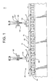
- FIG. 1 is a side view of a preferred embodiment of the present invention, longitudinally disposed along a row of containers being transported by a conveyor;
- FIG. 2 is a sectional view of a preferred embodiment of a pre-purge gassing rail apparatus, made in accordance with the present invention
- FIG. 3 is an isolated close-up view of the pre-purged gassing rail apparatus of FIG. 2;
- FIG. 4 is a sectional view of a preferred embodiment of a purge gassing rail apparatus, made in accordance with the present invention.
- FIG. 5 is an isolated close-up view of the purge gassing rail apparatus of FIG. 4.
- FIG. 6 is a sectional view of another preferred embodiment of a purge gassing rail apparatus, made in accordance with the present invention.
- the gassing rail apparatus generally includes an elongated rail 10 .
- the elongated rail 10 is disposed along a row of containers 44 traveling on a conveyor 40 along the elongated rail 10 in a direction of travel designated by arrow 42 .
- the gassing rail apparatus 8 includes a first deflecting member 26 and a second deflecting member 28 .
- Each of the deflecting members 26 , 28 has an arcuate shape, with an upward-turning end region 78 , 80 , respectively.
- each of the deflecting members 26 , 28 are preferably shaped so as to direct the flow of a controlled environment gas from the inlet 16 through an elongated open region 32 .
- the first deflecting member 26 is shaped to direct the flow of the controlled environment gas (along the path shown by arrow 46 ) from the inlet 16 around the arcuate curve 30 and into the container 44 (substantially along the path shown by arrow 48 ).
- the controlled environment gas is flushed out of the container 44 (along the path shown by arrow 50 ), and towards the second deflecting member 28 .
- the second deflecting member 28 is shaped to direct the flow of the controlled environment gas (substantially along the path shown by arrow 47 ) around the arcuate curve 31 and eventually out of the elongated open region 32 (along the path shown by arrow 51 ).
- the purge gassing rail apparatus 9 also includes a first deflecting member 27 and a second deflecting member 29 .
- Each of the deflecting members 27 , 29 has an arcuate shape, with an end region 82 , 84 , respectively.
- the end regions are generally shaped in a direction perpendicular to the container 44 or parallel with an elongated rail base member 14 .
- each of the deflecting members 27 , 29 are preferably shaped so as to direct the flow of a controlled environment gas from the inlets 34 , 36 , 38 through the elongated open region 32 .
- the first deflecting member 27 is shaped to direct the flow of the controlled environment gas (along the path shown by arrow 58 ) from the inlet 34 around the arcuate curve 74 and out of the elongated open region 32 .
- the second deflecting member 29 is shaped to direct the flow of the controlled environment gas (along the path shown by arrow 68 ) from inlet 38 around the arcuate curve 76 and out of the elongated open region 32 .
- Controlled environment gas from inlet 36 enters the container 44 , flows throughout the container 44 (substantially along the path shown by arrows 62 , 72 ) and eventually flows out of the container 44 (substantially along the path shown by arrows 64 , 66 ).
- the controlled environment gas flowing out of the container then exits the elongated open region 32 .
- the elongated rail 10 may be composed of two 2 ft. sections 60 , 70 . Alternatively, sections of various lengths may be used and positioned in series to create the desired length of elongated rail 10 . For example, elongated rail sections having a length of 3-12 inches may be combined with 2 ft. sections.
- the elongated rail 10 should preferably be at least as wide, and more preferably, somewhat wider, than the opening of the container 44 . The purpose for this will be described in detail below with reference to the elongated open region 32 .
- the elongated rail 10 may also be narrower than the container 44 opening, but under certain conditions, this may allow outside air to contaminate the container 44 . Structure or other means may be combined with the narrower elongated rail 10 to maintain the controlled environment.
- the length of the elongated rail 10 may vary depending on the desired line speed and minimum residence time underneath the elongated rail 10 for each container 44 . Also, a plurality of elongated rail sections may be arranged lengthwise in series to create a greater “effective” length. The actual length or number of elongated rail sections required will depend on various factors, including conveyor speed, container and product volume, and product type. Additionally, elongated rail 10 may be controlled to follow various production guidelines (i.e., it may be curved).
- the elongated rail 10 may preferably include an elongated rail top member 12 and an elongated rail base member 14 .
- the elongated rail top member 12 and the elongated rail base member 14 are in longitudinal communication with each other; that is, they are situated parallel with each other substantially throughout the length of the elongated rail 10 in a manner such that the elongated rail top member 12 may be located directly above the elongated rail base member 14 .
- Both the elongated rail base member and the elongated rail top member 12 , 14 may be made of any known material capable of achieving the purposes of the present invention, such as, for example, stainless steel or plastic.
- the elongated rail top member 12 and the elongated rail base member 14 may be attached to each other by any known means, such as for example, through a screw or through a nut-and-bolt assembly.
- the deflecting members 26 , 27 , 28 , 29 may also be made of any known material capable of achieving the purposes of the present invention, such as, for example, stainless steel or plastic.
- the attachment of the deflecting members 26 , 27 , 28 , 29 to the elongated rail base member 14 may be by any known means, such as, for example, through a screw or nut-and-bolt assembly.
- the attachment means described here may further include a plurality of o-rings 86 to ensure an airtight seal.
- elongated rail top member and “elongated rail base member,” it is contemplated that the elongated rail 10 may be inverted or positioned in various configurations where the elongated rail top member 12 is not completely disposed over the elongated rail base member 14 .
- FIGS. 2-3 one gas inlet 16 is shown. However, it is contemplated that the present invention may include more than one gas inlet.
- FIGS. 4-5 includes a first gas inlet 34 , a second gas inlet 36 and a third gas inlet 38 , the purpose of which will be described in detail below.
- the gas inlet 16 receives a controlled environment gas.
- the controlled environment gas enters the gas inlet 16 in a direction represented by arrow 18 .
- the gas inlet 16 may force the controlled environment gas into the elongated open region 32 by a speed of, for example, 10-200 liters per minute (LPM).
- LPM liters per minute
- the longitudinally oriented manifold 20 in conjunction with gassing element 22 , preferably serves to allow the outflow of the controlled environment gas from the gas inlet 16 , via the direction represented by arrow 18 , into the elongated open region 32 .
- the dual laminar screen member 24 preferably comprises the longitudinally oriented manifold 20 and gassing element 22 .
- the dual laminar screen member 24 preferably controls the outflow of the controlled environment gas, regulating, for example, such factors as velocity and direction.
- the first deflecting member 26 is preferably attached to a bottom side of the elongated rail 10 at one end of the elongated rail 10 .
- the first deflecting member 26 is attached at the left side of the elongated rail 10 .
- the second deflecting member 28 is preferably attached to the bottom side of the elongated rail 10 at an opposing end of the elongated rail 10 .
- the second deflecting member 28 is attached at the right side of the elongated rail 10 .
- the first deflecting member 26 and the second deflecting member 28 forms the first deflecting member curve 30 and the second deflecting member curve 31 , respectively.
- the first deflecting member curve 30 is preferably shaped in an arcuate contour to direct the flow of the controlled environment gas exiting the manifold 20 in a direction transverse to the path of the container 44 and into the open container 44 .
- the first deflecting member curve 30 also includes an upward-turning end region 78 which assists in directing the flow of the controlled environment gas along a path that the container 44 .
- the second deflecting member curve 31 is preferably shaped in an arcuate contour to direct the flow of the controlled environment gas exiting the container 44 in a direction transverse to the path of the container 44 and out of the elongated open region 32 .
- the second deflecting member curve 31 may also preferably include an upward-turning end region 80 which assists in directing the flow of the controlled environment gas exiting the container 44 through the elongated open region 32 .
- the first deflecting member curve 30 and the second deflecting member curve 31 form the boundary of the elongated open region 32 , in which the container 44 is positioned.
- the deflecting member curves 30 , 31 operate to direct the controlled environment gas flow to a container 44 located within the elongated open region 32 (see arrow 46 ), through the container 44 (see arrow 48 ), away from the container 44 and the elongated rail deflecting member 30 (see arrow 50 ), and out of the elongated open region 32 (see arrow 51 ).
- one section of the pre-purge rail apparatus 8 may include the following preferred dimensions, although it should be noted that the apparatus may include alternative dimensions.
- the deflecting member curves 30 , 31 are preferably 0.480 inches thick (see C).
- the controlled environment gas enters the elongated open region 32 , through the longitudinally oriented manifold 20 (which preferably contains an opening of 0.062 inches—see D) and gassing element 22 , via an opening of preferably 0.188 inches (see E).
- the first deflecting member 26 is preferably, at the most, 0.281 inches from the bottom of the elongated rail base member 14 (see F).
- the upward-turning end region 78 is 0.213 inches from the bottom of the elongated rail base member 14 (see G).
- the same dimensions are maintained at the second deflecting member 28 .
- the distance between the first deflecting member 26 and the second deflecting member 28 may be 0.844 inches at the closest point (see H) and 1.940 inches at the farthest point (see I).
- the pre-purge rail apparatus 8 may be made of any known material capable of achieving the purposes of the present invention, such as, for example, stainless steel or plastic.
- the pre-purge rail apparatus 8 operates in the following manner.
- the first deflecting member 26 is positioned to receive the flow of the controlled environment gas from the manifold 20 (represented by arrow 18 ).
- the first deflecting member 26 then redirects the controlled environment gas towards an opening formed by the boundaries of the first deflecting member curve 30 and the upward-turning end region 78 (arrow 46 ). That is, the curve, which forms the shape of the first deflecting member 26 , redirects the controlled environment gas towards the center of the elongated open region 32 .
- the container 44 is located at the center of the elongated open region 32 .
- the controlled environment gas then enters the container 44 (arrow 48 ) in a preferred gas profile to purge the environment within the container 44 .
- the gas then exits the container 44 (arrow 50 ).
- the second deflecting member 28 directs the gas exiting the container 44 out of the elongated open region 32 (arrow 50 ). The second deflecting member does this by the boundaries of the second deflecting member curve 31 and the upward-turning end region 80 .
- the principle directing the flow of the controlled environment gas through the elongated rail deflecting member 30 may operate according to the Coanda principle.
- the Coanda principle specifies that a stream of fluid or air will tend to follow the surface of a solid which is curved slightly in a direction away from the stream.
- the Coanda principle is further described in additional detail at www.cfcl.com/jef/coanda_effect.html, the contents of which are fully incorporated herein.
- the illustrated preferred embodiment of the purge rail apparatus 9 is similar to the pre-purge rail apparatus 8 disclosed and discussed with regards to FIGS. 2-3. However, at least one distinct difference exists.
- FIG. 4 there are a total of three gas inlets, noted by reference numerals 34 , 36 and 38 , respectively.
- the purge rail apparatus 9 may be used with a product within the containers 44 , which include product.
- the flow of controlled environment gas directed into the container 44 is preferably at a rate that will effectively pruge the existing environment within the product-filled container 44 .
- first and third gas inlets 34 , 38 may be operated at, for example, 10-40 LPM.
- Second gas inlet 36 which feeds the gassing rail positioned directly over the containers 44 , may be operated at, for example, 30-100 LPM.
- the flow rate for the second gas inlet 36 may be greater than that for the first and third gas inlets 34 , 38 .
- the purge rail apparatus 9 includes a first manifold 21 , a second manifold 23 and a third manifold 25 , wherein the first manifold 21 is positioned between the second manifold 23 and the third manifold 25 .
- the purge rail apparatus includes three gas inlets 34 , 36 , 38 .
- the purge rail apparatus 9 may include two gas inlets, and still perform the method of the present invention. In such a case, the purge rail apparatus 9 would have a middle gas inlet (similar to 36 ) and one side inlet (either 34 or 38 ).
- each manifold 21 , 23 , 25 is designated by arrows 52 , 54 and 56 .
- the controlled environment gas exiting through the second manifold 23 supplied by the first gas inlet 34 is deflected by the first deflecting member 27 as shown by arrow 58 .
- the controlled environment gas exiting the first manifold 21 by the second gas inlet 36 enters the container 44 as shown by arrows 72 and 62 , developing a pre-formed flow profile, and exits the container 44 by arrows 64 and 66 .
- the controlled environment gas exiting the third manifold 25 supplied by the third gas inlet 38 is deflected by the second deflecting member 29 as shown by arrow 68 .
- the deflecting members 27 , 29 include a first deflecting member curve 74 and the second deflecting member curve 76 , respectively. Additionally, both the first deflecting member curve 74 and the second deflecting member curve 76 are preferably shaped in an arcuate contour to direct the airflow of the controlled environment gas.
- the first deflecting member curve 74 includes an end region 82 which directs the flow of the controlled environment gas from inlet 34 out of the elongated open region 32 .
- the second deflecting member curve 76 includes an end region 84 which directs the flow of the controlled environment gas from inlet 38 out of the elongated open region 32 .
- the end regions 82 , 84 are shaped in a manner parallel to the elongated rail base member 14 , to direct the flow of the controlled environment gas out of the elongated open region 32 .
- one section of the rail apparatus 9 may include the following preferred dimensions, although it should be noted that the rail apparatus 9 may include alternative dimensions.
- the elongated rail deflecting member 30 is preferably 0.480 inches thick (see J).
- the controlled environment gas enters the elongated open region 32 (via the first and third gas inlets 34 , 38 ) through the second and third longitudinally oriented manifolds 23 , 25 (which preferably contains an opening of 0.062 inches—see K) and gassing element 22 , entering the elongated open region 32 via an opening of preferably 0.188 inches (see L).
- the controlled environment gas enters the elongated open region 32 (via the second gas inlet 36 ) through the first longitudinally oriented manifold 21 (which preferably contains an opening of 0.062 inches—see M) and gassing element 22 , entering the elongated open region 32 via an opening of preferably 0.156 inches (see N).
- the first deflecting member 27 is preferably positioned, for example, 0.375 inches from the bottom of the elongated rail base member 14 (see Q).
- the end region 78 maintains a radius of 0.100 inches (see R).
- the same dimensions are maintained at the second deflecting member 28 .
- the distance between the first deflecting member 27 and the second deflecting member 29 is preferably, for example, 0.979 inches at the closest point (see O) and 1.944 inches at the farthest point (see P).
- the purge rail apparatus 9 may be made of any known material capable of achieving the purposes of the present invention, such as, for example, stainless steel or plastic.
- a preferred embodiment of a system for exposing a container 44 to a controlled environment is as follows.
- a container 44 is passed along the pre-purge rail apparatus 8 .
- the container 44 may be passed along the pre-purge rail apparatus 8 through any known means of conveyance, such as, for example, a conveyor belt.
- a controlled environment gas is supplied through the manifold 20 , and is deflected by the first deflecting member 26 (which includes the first deflecting member curve 30 and the upward-turning end region 78 ) into the container 44 (arrows 46 and 48 ).
- the controlled environment gas then circulates through the container 44 in a preferred flow profile.
- the gas exiting the container 44 (arrow 50 ) is deflected by the second deflecting member 28 (which includes the second deflecting member curve 31 and the upward-turning end region 80 ), out of the elongated open region 32 .
- the container 44 which may, at this point, include a product, is then passed along the purge rail apparatus 9 .
- the method of passing the container 44 along the purge rail apparatus 9 is similar to the method of passing the container 44 along the pre-purge rail apparatus 8 , as described above.
- a controlled environment gas is supplied into the elongated open region 32 .
- the controlled environment gas is supplied into the elongated open region 32 through the three gas inlets 34 , 36 , 38 .
- the controlled environment gas is deflected towards the opening within the elongated open region 32 between the container 44 and the first deflecting member 27 (arrow 58 ).
- the gas flowing from the first manifold 21 provides a lateral shield of controlled environment gas to prevent the migration of oxygen or other contaminating environment into the elongated open region 32 . In this way, the product contained within the container 44 will not be contaminated by outside air.
- the gassing system also provides a highly controlled flow pattern within the elongated open region 32 . A Venturi effect may also be created by the flow, which drives the exhaust controlled environment gases out of the elongated open region 32 . This allows the flow exiting the container 44 to be directed out of the container 44 and the elongated open region 32 . Additionally, this prevents the build up of air within the elongated open region 32 .
- the controlled environment gas exiting the third manifold 25 is deflected through the elongated open region 32 between the container 44 and the second deflecting member 29 (arrow 68 ).
- the flow from the third gas inlet 38 is similar to that described above with regards to the flow from the first gas inlet 34 .
- the operation of the third gas inlet 38 with the second deflecting member 29 is a mirror image of the operation of the first gas inlet 34 with the first deflecting member 27 .
- the controlled environment gas exiting the first manifold 21 enters the container 44 , creating a centerline purge as shown in FIGS. 4-5 (arrows 62 , 72 ).
- the controlled environment gas then circulates within the container 44 , exits the container 44 , and is deflected out of the elongated open region 32 (arrows 64 , 66 ) and with the assistance of the flow from both the first and third manifolds 20 (arrows 58 , 68 ).
- the purge rail apparatus 9 may be designed and implemented without either the first or second deflecting members 27 , 29 .
- a Venturi effect may still apply to direct the flow of the controlled environment gas out of the container 44 .
- the outside manifolds i.e., the second manifold and the third manifold
- the Venturi effect of the flows (arrows 58 and 68 ) causes the controlled environment gas exiting the container 44 (arrows 64 and 66 ) to exit the open elongated region 32 .
- This embodiment may be utilized to evacuate and sterilize a large container 44 without disturbing the product contained within.
Abstract
Description
Claims (22)
Priority Applications (1)
| Application Number | Priority Date | Filing Date | Title |
|---|---|---|---|
| US09/616,186 US6691747B1 (en) | 2000-07-14 | 2000-07-14 | Method and apparatus for exposing a container to a controlled environment |
Applications Claiming Priority (1)
| Application Number | Priority Date | Filing Date | Title |
|---|---|---|---|
| US09/616,186 US6691747B1 (en) | 2000-07-14 | 2000-07-14 | Method and apparatus for exposing a container to a controlled environment |
Publications (1)
| Publication Number | Publication Date |
|---|---|
| US6691747B1 true US6691747B1 (en) | 2004-02-17 |
Family
ID=31188864
Family Applications (1)
| Application Number | Title | Priority Date | Filing Date |
|---|---|---|---|
| US09/616,186 Expired - Lifetime US6691747B1 (en) | 2000-07-14 | 2000-07-14 | Method and apparatus for exposing a container to a controlled environment |
Country Status (1)
| Country | Link |
|---|---|
| US (1) | US6691747B1 (en) |
Cited By (21)
| Publication number | Priority date | Publication date | Assignee | Title |
|---|---|---|---|---|
| US20040168739A1 (en) * | 2001-04-20 | 2004-09-02 | Bonney Stanley George | Metering method for particulate material |
| US20060231156A1 (en) * | 2005-04-15 | 2006-10-19 | Marcus Frank F | Apparatus and method for exposing a container to a controlled environment |
| US20060231157A1 (en) * | 2005-04-15 | 2006-10-19 | Marcus Frank F | Apparatus and method for exposing a container to a controlled environment |
| US20060254217A1 (en) * | 2005-04-15 | 2006-11-16 | Marcus Frank F | Multiflow gassing system |
| US20070012377A1 (en) * | 2003-12-11 | 2007-01-18 | Popplau Jens H | Container treatment device with a gas curtain |
| US7241066B1 (en) | 2003-04-15 | 2007-07-10 | American Grease Stick Company | Container for flowable products |
| US20080011386A1 (en) * | 2006-05-23 | 2008-01-17 | Comecer S.P.A. | Ventilation assembly for a machine for the preparation of radiopharmaceuticals |
| US20090013648A1 (en) * | 2007-07-11 | 2009-01-15 | Stokely-Van Camp, Inc. | Active Sterilization Zone for Container Filling |
| US20090101178A1 (en) * | 2007-10-22 | 2009-04-23 | Stokely-Van Camp, Inc | Container Rinsing System and Method |
| US20100021359A1 (en) * | 2005-09-30 | 2010-01-28 | Dirk Auer | Apparatus for Sterilizing Containers Transported Continuously in Succession |
| US20100252142A1 (en) * | 2007-11-13 | 2010-10-07 | Sidel Participations | Unit for filling containers, comprising an insulator, especially for a production installation |
| WO2011002382A1 (en) * | 2009-07-03 | 2011-01-06 | Tetra Laval Holdings & Finance S.A. | A device and a method for maintaining a gas flow barrier between two volumes of a channel |
| US8061563B1 (en) | 2007-05-29 | 2011-11-22 | Ags I-Prop, Llc | Flexible pouch with expulsion aid |
| US8376183B1 (en) | 2008-06-10 | 2013-02-19 | Ags I-Prop, Llc | Fluid dispenser having multiple chambers |
| RU2528691C2 (en) * | 2009-07-03 | 2014-09-20 | Тетра Лаваль Холдингз Энд Файнэнс С.А. | Method and device for maintaining barrier of gas flow between two connected capacities |
| US9168569B2 (en) | 2007-10-22 | 2015-10-27 | Stokely-Van Camp, Inc. | Container rinsing system and method |
| WO2016142491A1 (en) * | 2015-03-10 | 2016-09-15 | Krones Ag | Device and method for treating a container with a treatment medium |
| DE102017221193A1 (en) * | 2017-11-27 | 2019-05-29 | Bausch + Ströbel Maschinenfabrik Ilshofen GmbH + Co. KG | Closing device for gassing and closing of containers having a filling opening |
| CN110300604A (en) * | 2016-12-20 | 2019-10-01 | 克朗斯公司 | With the hydrogen peroxide treatment system component of vaporization and/or the device of packaging material |
| US10793304B2 (en) | 2011-05-04 | 2020-10-06 | Dole Fresh Vegetables, Inc. | High-flow, low-velocity gas flushing system for reducing and monitoring oxygen content in packaged produce containers |
| US11312521B2 (en) * | 2018-12-28 | 2022-04-26 | Shibuya Packaging System Corporation | Container packaging apparatus |
Citations (4)
| Publication number | Priority date | Publication date | Assignee | Title |
|---|---|---|---|---|
| US4707334A (en) * | 1985-06-27 | 1987-11-17 | Kolubus Gmbh & Co. Kg | Isolation method and apparatus for sterilizing chambers of filling machines |
| US5178841A (en) * | 1990-10-13 | 1993-01-12 | Fmc Corporation | Sterilizing apparatus |
| US5368828A (en) * | 1992-11-12 | 1994-11-29 | Tetra Laval Holdings & Finance S.A. | Method and apparatus for carton sterilization |
| US6120730A (en) * | 1998-06-26 | 2000-09-19 | Tetra Laval Holdings & Finance, Sa | Heat and hydrogen peroxide gas sterilization of container |
-
2000
- 2000-07-14 US US09/616,186 patent/US6691747B1/en not_active Expired - Lifetime
Patent Citations (4)
| Publication number | Priority date | Publication date | Assignee | Title |
|---|---|---|---|---|
| US4707334A (en) * | 1985-06-27 | 1987-11-17 | Kolubus Gmbh & Co. Kg | Isolation method and apparatus for sterilizing chambers of filling machines |
| US5178841A (en) * | 1990-10-13 | 1993-01-12 | Fmc Corporation | Sterilizing apparatus |
| US5368828A (en) * | 1992-11-12 | 1994-11-29 | Tetra Laval Holdings & Finance S.A. | Method and apparatus for carton sterilization |
| US6120730A (en) * | 1998-06-26 | 2000-09-19 | Tetra Laval Holdings & Finance, Sa | Heat and hydrogen peroxide gas sterilization of container |
Cited By (40)
| Publication number | Priority date | Publication date | Assignee | Title |
|---|---|---|---|---|
| US7621300B2 (en) * | 2001-04-20 | 2009-11-24 | Glaxo Group Limited | Metering method for particulate material |
| US20040168739A1 (en) * | 2001-04-20 | 2004-09-02 | Bonney Stanley George | Metering method for particulate material |
| US7241066B1 (en) | 2003-04-15 | 2007-07-10 | American Grease Stick Company | Container for flowable products |
| US7357159B2 (en) * | 2003-12-11 | 2008-04-15 | Popplau Jens H | Container treatment device with a gas curtain |
| US20070012377A1 (en) * | 2003-12-11 | 2007-01-18 | Popplau Jens H | Container treatment device with a gas curtain |
| US20060254217A1 (en) * | 2005-04-15 | 2006-11-16 | Marcus Frank F | Multiflow gassing system |
| US7412811B2 (en) | 2005-04-15 | 2008-08-19 | Packaging Technologies, Inc. | Multiflow gassing system |
| US20060231157A1 (en) * | 2005-04-15 | 2006-10-19 | Marcus Frank F | Apparatus and method for exposing a container to a controlled environment |
| US20060231156A1 (en) * | 2005-04-15 | 2006-10-19 | Marcus Frank F | Apparatus and method for exposing a container to a controlled environment |
| US7690404B2 (en) | 2005-04-15 | 2010-04-06 | Clear Lam Packaging, Inc. | Apparatus and method for exposing a container to a controlled environment |
| US8591826B2 (en) * | 2005-09-30 | 2013-11-26 | Sig Technology Ag | Apparatus for sterilizing containers transported continuously in succession |
| US20100021359A1 (en) * | 2005-09-30 | 2010-01-28 | Dirk Auer | Apparatus for Sterilizing Containers Transported Continuously in Succession |
| US20080011386A1 (en) * | 2006-05-23 | 2008-01-17 | Comecer S.P.A. | Ventilation assembly for a machine for the preparation of radiopharmaceuticals |
| US7905258B2 (en) * | 2006-05-23 | 2011-03-15 | Comecer S.P.A. | Ventilation assembly for a machine for the preparation of radiopharmaceuticals |
| US8061563B1 (en) | 2007-05-29 | 2011-11-22 | Ags I-Prop, Llc | Flexible pouch with expulsion aid |
| US9296600B2 (en) | 2007-07-11 | 2016-03-29 | Stokely-Van Camp, Inc. | Active sterilization zone for container filling |
| US9321620B2 (en) | 2007-07-11 | 2016-04-26 | Stokely-Van Camp, Inc. | Active sterilization zone for container filling |
| US20120124941A1 (en) * | 2007-07-11 | 2012-05-24 | Stokely-Van Camp, Inc. | Active sterilization zone for container filling |
| US20090013648A1 (en) * | 2007-07-11 | 2009-01-15 | Stokely-Van Camp, Inc. | Active Sterilization Zone for Container Filling |
| US8567454B2 (en) * | 2007-07-11 | 2013-10-29 | Stokely-Van Camp, Inc. | Active sterilization zone for container filling |
| US20090017747A1 (en) * | 2007-07-11 | 2009-01-15 | Stokely-Van Camp, Inc. | Active Sterilization Zone for Container Filling |
| US9168569B2 (en) | 2007-10-22 | 2015-10-27 | Stokely-Van Camp, Inc. | Container rinsing system and method |
| US20090101178A1 (en) * | 2007-10-22 | 2009-04-23 | Stokely-Van Camp, Inc | Container Rinsing System and Method |
| US8147616B2 (en) | 2007-10-22 | 2012-04-03 | Stokely-Van Camp, Inc. | Container rinsing system and method |
| US20100252142A1 (en) * | 2007-11-13 | 2010-10-07 | Sidel Participations | Unit for filling containers, comprising an insulator, especially for a production installation |
| US8701720B2 (en) * | 2007-11-13 | 2014-04-22 | Sidel Participations | Unit for filling containers, comprising an insulator, especially for a production installation |
| US8376183B1 (en) | 2008-06-10 | 2013-02-19 | Ags I-Prop, Llc | Fluid dispenser having multiple chambers |
| EP2448826A4 (en) * | 2009-07-03 | 2012-11-28 | Tetra Laval Holdings & Finance | A device and a method for maintaining a gas flow barrier between two volumes of a channel |
| RU2528691C2 (en) * | 2009-07-03 | 2014-09-20 | Тетра Лаваль Холдингз Энд Файнэнс С.А. | Method and device for maintaining barrier of gas flow between two connected capacities |
| JP2016027985A (en) * | 2009-07-03 | 2016-02-25 | テトラ ラバル ホールデイングス エ フイナンス ソシエテ アノニム | Device and method for maintaining gas flow barrier between two volumes of channel |
| WO2011002382A1 (en) * | 2009-07-03 | 2011-01-06 | Tetra Laval Holdings & Finance S.A. | A device and a method for maintaining a gas flow barrier between two volumes of a channel |
| EP2448826A1 (en) * | 2009-07-03 | 2012-05-09 | Tetra Laval Holdings & Finance S.A. | A device and a method for maintaining a gas flow barrier between two volumes of a channel |
| US10793304B2 (en) | 2011-05-04 | 2020-10-06 | Dole Fresh Vegetables, Inc. | High-flow, low-velocity gas flushing system for reducing and monitoring oxygen content in packaged produce containers |
| WO2016142491A1 (en) * | 2015-03-10 | 2016-09-15 | Krones Ag | Device and method for treating a container with a treatment medium |
| CN110300604A (en) * | 2016-12-20 | 2019-10-01 | 克朗斯公司 | With the hydrogen peroxide treatment system component of vaporization and/or the device of packaging material |
| US20200114031A1 (en) * | 2016-12-20 | 2020-04-16 | Krones Ag | Device for treating system components and/or packaging means using vaporized hydrogen peroxide |
| JP2020513868A (en) * | 2016-12-20 | 2020-05-21 | クロネス アーゲー | Device for treating system components and / or packaging means with vaporized hydrogen peroxide |
| DE102017221193A1 (en) * | 2017-11-27 | 2019-05-29 | Bausch + Ströbel Maschinenfabrik Ilshofen GmbH + Co. KG | Closing device for gassing and closing of containers having a filling opening |
| US11414229B2 (en) * | 2017-11-27 | 2022-08-16 | Bausch + Ströbel Maschinenfabrik Ilshofen GmbH + Co. KG | Closure device for adding gas to and closing containers that have a filler opening |
| US11312521B2 (en) * | 2018-12-28 | 2022-04-26 | Shibuya Packaging System Corporation | Container packaging apparatus |
Similar Documents
| Publication | Publication Date | Title |
|---|---|---|
| US6691747B1 (en) | Method and apparatus for exposing a container to a controlled environment | |
| US4791775A (en) | Packaging device | |
| US6032438A (en) | Apparatus and method for replacing environment within containers with a controlled environment | |
| US7412811B2 (en) | Multiflow gassing system | |
| US5201165A (en) | Gas displacement device for packaging food and non-food products | |
| JPH0632329A (en) | Device for sealing tray and charging gas | |
| US20060231157A1 (en) | Apparatus and method for exposing a container to a controlled environment | |
| CA1216536A (en) | Vertical single filer conveyor system | |
| US5417255A (en) | Gas flushing apparatus and method | |
| US7690404B2 (en) | Apparatus and method for exposing a container to a controlled environment | |
| US5816024A (en) | Apparatus and method for exposing product to a controlled environment | |
| US6202388B1 (en) | Controlled environment sealing apparatus and method | |
| US9718569B2 (en) | Modified atmospheric flow-wrap system | |
| US5911249A (en) | Gassing rail apparatus and method | |
| US5085035A (en) | Gas displacement device for packaging food and non-food products | |
| JPS63258725A (en) | Production unit for airtight package having inert atmosphere | |
| US10745211B2 (en) | Diverting apparatus with Coanda stabilizing device | |
| JPH0742965Y2 (en) | Gas replacement device for can lid clamp | |
| JPH05338789A (en) | Carrying conveyor device for lightweight vessel | |
| JPH1111665A (en) | Sterilized pneumatic conveyor device | |
| JP2748255B2 (en) | Transport device for lightweight bottles | |
| JP2004262528A (en) | Method and device for inert gas substitution | |
| GB2135645A (en) | Air-bed conveyers | |
| JP2002029507A (en) | Method and device for replacing gas in head space of container |
Legal Events
| Date | Code | Title | Description |
|---|---|---|---|
| STCF | Information on status: patent grant |
Free format text: PATENTED CASE |
|
| REMI | Maintenance fee reminder mailed | ||
| FPAY | Fee payment |
Year of fee payment: 4 |
|
| SULP | Surcharge for late payment | ||
| AS | Assignment |
Owner name: CLEAR LAM PACKAGING, INC., ILLINOIS Free format text: RELEASE BY SECURED PARTY;ASSIGNOR:HARRIS N.A.;REEL/FRAME:020582/0071 Effective date: 20080229 |
|
| AS | Assignment |
Owner name: PACKAGING TECHNOLOGIES, INC., IOWA Free format text: ASSIGNMENT OF ASSIGNORS INTEREST;ASSIGNOR:CLEAR LAM PACKAGING, INC.;REEL/FRAME:020654/0821 Effective date: 20080303 Owner name: PACKAGING TECHNOLOGIES, INC.,IOWA Free format text: ASSIGNMENT OF ASSIGNORS INTEREST;ASSIGNOR:CLEAR LAM PACKAGING, INC.;REEL/FRAME:020654/0821 Effective date: 20080303 |
|
| REFU | Refund |
Free format text: REFUND - PAYMENT OF MAINTENANCE FEE, 8TH YR, SMALL ENTITY (ORIGINAL EVENT CODE: R2552); ENTITY STATUS OF PATENT OWNER: LARGE ENTITY |
|
| FEPP | Fee payment procedure |
Free format text: PAT HOLDER NO LONGER CLAIMS SMALL ENTITY STATUS, ENTITY STATUS SET TO UNDISCOUNTED (ORIGINAL EVENT CODE: STOL); ENTITY STATUS OF PATENT OWNER: LARGE ENTITY |
|
| FPAY | Fee payment |
Year of fee payment: 8 |
|
| FPAY | Fee payment |
Year of fee payment: 8 |
|
| SULP | Surcharge for late payment |
Year of fee payment: 7 |
|
| AS | Assignment |
Owner name: CLEAR-LAM PACKAGING, INC., ILLINOIS Free format text: MERGER;ASSIGNOR:JESCORP, INC.;REEL/FRAME:029303/0739 Effective date: 20001226 |
|
| AS | Assignment |
Owner name: OYSTAR NORTH AMERICA, INC., IOWA Free format text: ASSIGNMENT OF ASSIGNORS INTEREST;ASSIGNORS:SANFILIPPO, JOHN E;SANFILIPPO, JAMES J;REEL/FRAME:029365/0364 Effective date: 20121128 |
|
| AS | Assignment |
Owner name: OYSTAR NORTH AMERICA, INC., IOWA Free format text: ASSIGNMENT OF ASSIGNORS INTEREST;ASSIGNOR:MARCUS, FRANK F.;REEL/FRAME:029444/0833 Effective date: 20121208 |
|
| FPAY | Fee payment |
Year of fee payment: 12 |