US6693520B2 - Safety back-up sensor for a vehicle - Google Patents
Safety back-up sensor for a vehicle Download PDFInfo
- Publication number
- US6693520B2 US6693520B2 US10/081,472 US8147202A US6693520B2 US 6693520 B2 US6693520 B2 US 6693520B2 US 8147202 A US8147202 A US 8147202A US 6693520 B2 US6693520 B2 US 6693520B2
- Authority
- US
- United States
- Prior art keywords
- sensor
- jacket
- safety back
- resilient
- cylindrical jacket
- Prior art date
- Legal status (The legal status is an assumption and is not a legal conclusion. Google has not performed a legal analysis and makes no representation as to the accuracy of the status listed.)
- Expired - Fee Related, expires
Links
Images


Classifications
-
- G—PHYSICS
- G01—MEASURING; TESTING
- G01S—RADIO DIRECTION-FINDING; RADIO NAVIGATION; DETERMINING DISTANCE OR VELOCITY BY USE OF RADIO WAVES; LOCATING OR PRESENCE-DETECTING BY USE OF THE REFLECTION OR RERADIATION OF RADIO WAVES; ANALOGOUS ARRANGEMENTS USING OTHER WAVES
- G01S7/00—Details of systems according to groups G01S13/00, G01S15/00, G01S17/00
- G01S7/52—Details of systems according to groups G01S13/00, G01S15/00, G01S17/00 of systems according to group G01S15/00
- G01S7/521—Constructional features
-
- B—PERFORMING OPERATIONS; TRANSPORTING
- B60—VEHICLES IN GENERAL
- B60R—VEHICLES, VEHICLE FITTINGS, OR VEHICLE PARTS, NOT OTHERWISE PROVIDED FOR
- B60R19/00—Wheel guards; Radiator guards, e.g. grilles; Obstruction removers; Fittings damping bouncing force in collisions
- B60R19/02—Bumpers, i.e. impact receiving or absorbing members for protecting vehicles or fending off blows from other vehicles or objects
- B60R19/48—Bumpers, i.e. impact receiving or absorbing members for protecting vehicles or fending off blows from other vehicles or objects combined with, or convertible into, other devices or objects, e.g. bumpers combined with road brushes, bumpers convertible into beds
- B60R19/483—Bumpers, i.e. impact receiving or absorbing members for protecting vehicles or fending off blows from other vehicles or objects combined with, or convertible into, other devices or objects, e.g. bumpers combined with road brushes, bumpers convertible into beds with obstacle sensors of electric or electronic type
Definitions
- the present invention relates to a safety back-up sensor, in particular, a sensor with multiple resilient tabs on the shoulder to prevent shifting or rotation of the sensor body, allowing the sensor to be firmly affixed on a vehicle bumper.
- a conventional back-up sensor device includes a cylindrical body ( 40 ), an end plate ( 43 ), a rubber bushing ( 41 ) and a signal sensor module ( 42 ).
- a hollow core runs through the cylindrical body ( 40 ) to accommodate the rubber bushing ( 41 ) and the signal sensor module ( 42 ).
- the signal sensor module ( 42 ) emits ultrasonic signals through a through hole in the cylindrical body ( 40 ) to detect any object within its effective range.
- a hole is drilled in the rear bumper of the vehicle, in which the sensor device is installed.
- the security of the installation relies on the abrasion force of the external wall of the sensor against the inner wall of the installation hole to grip the device.
- the external wall of a conventional sensor body ( 40 ) usually has a smooth surface. A vehicle riding over bumpy roads is likely to cause rocking, bouncing and vibration of the vehicle chassis and the bumper. Over an extended period of time, the sensor body ( 40 ) will likely loosen or become detached from the installation hole.
- the signal sensor module ( 42 ) When assembling the conventional sensor device, the signal sensor module ( 42 ) is first inserted into the rubber bushing ( 41 ), and the rubber bushing ( 41 ) is slid into the body of sensor ( 40 ). As such, the sensor body indirectly exerts pressure on the perimeter of the signal sensor module, which may cause dislocation of the sensor leading to aberrations in signal transmission and reception. This phenomenon may well cause false alarms due to incorrect approximation of the distance between an object and the sensor device.
- the present invention provides a type of vehicle back-up sensor, wherein multiple directional and locating constructs are created on the shoulder of the external sensor body to ensure rigid installation of the back-up sensor on the vehicle bumper under all driving conditions.
- the safety back-up sensor presented in this invention comprises a cylindrical body with a hollow tubular core to accommodate a rubber bushing, in which a signal sensor module is installed on one end.
- the shoulder of the external sensor body has multiple convex-shaped resilient tabs having the appearance of a fretted carving.
- the top portion of each resilient tab is impressed with transverse teeth to prevent the sensor unit from shifting. Alternately, double ribs over transverse teeth are created on every other resilient tab to prevent the sensor unit from rotating. With these special features, the sensor unit can be firmly attached to the vehicle bumper.
- FIG. 1 is an exploded perspective view of the safety back-up sensor in accordance with the present invention
- FIG. 2 is a side view of the safety back-up sensor in FIG. 1;
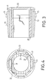
- FIG. 3 is a cross sectional side plan view of the safety back-up sensor in FIG. 2;
- FIG. 4 is a cross sectional bottom plan view of the safety back-up sensor in FIG. 1;
- FIG. 5 is an exploded perspective view of a conventional sensor back-up device for a vehicle in accordance with the prior art.
- the safety back-up sensor in accordance with the present invention comprises a cylindrical jacket ( 10 ), a rubber bushing ( 20 ), a signal-sensing transceiver ( 30 ) and an end plate ( 35 ).
- the cylindrical jacket ( 10 ) has a hollow center, two open ends and an inside and outside surface.
- the hollow center extends to the outside through an integrated bezel ( 11 ) at one end.
- Pairs of parallel longitudinal through slots ( 12 ) are formed through the cylindrical jacket ( 10 ).
- Each longitudinal through slot ( 12 ) has two ends, and the ends of each pair is connected by a transverse through slot (not numbered) at the end adjacent to the bezel ( 11 ) to form a resilient tab ( 13 ) between each pair of longitudinal through slots ( 12 ).
- An outside surface of each resilient tab ( 13 ) extends out from the outside surface of the cylindrical jacket ( 10 ) in a triangular configuration.
- four resilient tabs ( 13 ) are disposed in parallel.
- the parallel resilient tabs ( 13 ) extend from near one end of the cylindrical jacket ( 10 ) toward the bezel ( 11 ) but do not touch the bezel ( 11 ), thus forming a free end.
- transverse teeth ( 14 ) are formed on the outside portion of alternate resilient tabs ( 13 ) toward the free end.
- Parallel ribs ( 15 ) are formed on the other resilient tabs ( 13 ).
- a rectangular engagement hole ( 16 ) is formed near the attached end of each resilient tab ( 13 ).
- An axial channel ( 17 ) is formed between adjacent pairs of resilient tabs ( 13 ) on the inner surface on the jacket ( 10 ) to hold the rubber bushing ( 20 ) in place.
- the external wall of the rubber bushing ( 20 ) has multiple parallel grooves ( 21 ) and multiple ridges ( 22 ).
- the grooves ( 21 ) correspond to the positions of resilient tabs ( 13 ) on the jacket ( 10 ).
- the ridges ( 22 ) correspond to the axial channels ( 17 ) on the inner surface of the jacket ( 10 ).
- the signal sensor module ( 30 ) is inserted into one end of the rubber bushing ( 20 ).
- the rubber bushing ( 20 ) is slid into the jacket ( 10 ).
- the end plate ( 35 ) is fit into the end of the jacket ( 10 ) opposite from the bezel ( 11 ) to securely hold the bushing ( 20 ) in the jacket ( 20 ).
- the end plate ( 35 ) has an outer edge (not numbered) with multiple locking tabs ( 36 ) corresponding to the positions of engagement holes ( 16 ) on the jacket ( 10 ). These locking tabs ( 36 ) allow the end plates ( 35 ) to be rigidly attached to the jacket ( 10 ).
- each ridge ( 22 ) on the rubber bushing ( 20 ) is lodged in the corresponding channel ( 17 ) on the inner wall of the jacket ( 10 ), so that the rubber bushing ( 20 ) can be firmly affixed to prevent turning of one part in relation to the other.
- the external wall of the rubber bushing ( 20 ) has multiple parallel grooves ( 21 ) corresponding to the positions of resilient tabs ( 13 ) on the jacket ( 10 ), so that in between the rubber bushing ( 20 ) and the jacket ( 10 ) a gap is formed.
- the protruding resilient tab ( 13 ) on the cylindrical body ( 10 ) produces a strong gripping force on the inner wall of the hole used for installation of the sensor body, so that the sensor body can be firmly affixed on the vehicle bumper.
- the transverse teeth ( 14 ) present on the resilient tab ( 13 ) are used to further increase the abrasion force against the inner wall of the installation hole to prevent shifting of the sensor body ( 10 ), and the ribs ( 15 ) are designed to counter the rotational force on the sensor body.
- the present invention provides a safety back-up sensor that can be rigidly installed in a vehicle bumper by means of and the protruding resilient tabs with transverse teeth and ribs. It is apparent that the back-up sensor with the improved body structure is capable of enhancing the efficacy in giving warning of the proximity of an object compared to conventional sensor devices.
Abstract
A safety back-up sensor, formed with a cylindrical jacket with two ends and a hollow core between the two ends to accommodate a rubber bushing and a signal sensor module. Multiple parallel longitudinal resilient tabs are formed on the cylindrical jacket. The resilient tabs protrude from the exterior surface of the cylindrical jacket and have transverse teeth to prevent the senor body from being dislodged. Longitudinal ribs are formed on alternate resilient tabs to prevent the sensor body from rotating. With these specially designed transverse teeth and ribs, the sensor is able to counter the external rotating and shifting forces present in various driving conditions and to firmly affix the sensor to a vehicle bumper.
Description
1. Field of the Invention
The present invention relates to a safety back-up sensor, in particular, a sensor with multiple resilient tabs on the shoulder to prevent shifting or rotation of the sensor body, allowing the sensor to be firmly affixed on a vehicle bumper.
2. Description of Related Art
When an ordinary user wants to install a sensor deice in the vehicle, his or her main consideration is the accuracy in detecting the proximity of an object. Elements causing false alarms of the electronic sensor can be either external factors or circuit design problems. The user wants to know whether the sensor device is capable of distinguishing actual objects from noises and accurately approximating the distance between the vehicle and the object, based on the reflection of ultrasonic signals emitted. A primary consideration is whether the sensor is rigidly installed in place so the device can function properly.
With reference to FIG. 5, a conventional back-up sensor device includes a cylindrical body (40), an end plate (43), a rubber bushing (41) and a signal sensor module (42). A hollow core runs through the cylindrical body (40) to accommodate the rubber bushing (41) and the signal sensor module (42). The signal sensor module (42) emits ultrasonic signals through a through hole in the cylindrical body (40) to detect any object within its effective range.
In the conventional method of installing a sensor device, a hole is drilled in the rear bumper of the vehicle, in which the sensor device is installed. When the sensor device is inserted into the bumper, the security of the installation relies on the abrasion force of the external wall of the sensor against the inner wall of the installation hole to grip the device. The external wall of a conventional sensor body (40) usually has a smooth surface. A vehicle riding over bumpy roads is likely to cause rocking, bouncing and vibration of the vehicle chassis and the bumper. Over an extended period of time, the sensor body (40) will likely loosen or become detached from the installation hole.
When assembling the conventional sensor device, the signal sensor module (42) is first inserted into the rubber bushing (41), and the rubber bushing (41) is slid into the body of sensor (40). As such, the sensor body indirectly exerts pressure on the perimeter of the signal sensor module, which may cause dislocation of the sensor leading to aberrations in signal transmission and reception. This phenomenon may well cause false alarms due to incorrect approximation of the distance between an object and the sensor device.
To overcome the shortcoming in the conventional sensor device mentioned above, the present invention provides a type of vehicle back-up sensor, wherein multiple directional and locating constructs are created on the shoulder of the external sensor body to ensure rigid installation of the back-up sensor on the vehicle bumper under all driving conditions.
The safety back-up sensor presented in this invention comprises a cylindrical body with a hollow tubular core to accommodate a rubber bushing, in which a signal sensor module is installed on one end. The shoulder of the external sensor body has multiple convex-shaped resilient tabs having the appearance of a fretted carving. The top portion of each resilient tab is impressed with transverse teeth to prevent the sensor unit from shifting. Alternately, double ribs over transverse teeth are created on every other resilient tab to prevent the sensor unit from rotating. With these special features, the sensor unit can be firmly attached to the vehicle bumper.
Other objectives, advantages, and novel features of the invention will become apparent from the detailed description when taken in conjunction with the attached drawings.
FIG. 1 is an exploded perspective view of the safety back-up sensor in accordance with the present invention;
FIG. 2 is a side view of the safety back-up sensor in FIG. 1;
FIG. 3 is a cross sectional side plan view of the safety back-up sensor in FIG. 2;
FIG. 4 is a cross sectional bottom plan view of the safety back-up sensor in FIG. 1;
FIG. 5 is an exploded perspective view of a conventional sensor back-up device for a vehicle in accordance with the prior art.
With reference to FIGS. 1 and 2, the safety back-up sensor in accordance with the present invention comprises a cylindrical jacket (10), a rubber bushing (20), a signal-sensing transceiver (30) and an end plate (35).
The cylindrical jacket (10) has a hollow center, two open ends and an inside and outside surface. The hollow center extends to the outside through an integrated bezel (11) at one end. Pairs of parallel longitudinal through slots (12) are formed through the cylindrical jacket (10). Each longitudinal through slot (12) has two ends, and the ends of each pair is connected by a transverse through slot (not numbered) at the end adjacent to the bezel (11) to form a resilient tab (13) between each pair of longitudinal through slots (12). An outside surface of each resilient tab (13) extends out from the outside surface of the cylindrical jacket (10) in a triangular configuration. In the current embodiment four resilient tabs (13) are disposed in parallel. The parallel resilient tabs (13) extend from near one end of the cylindrical jacket (10) toward the bezel (11) but do not touch the bezel (11), thus forming a free end.
Multiple transverse teeth (14) are formed on the outside portion of alternate resilient tabs (13) toward the free end. Parallel ribs (15) are formed on the other resilient tabs (13). A rectangular engagement hole (16) is formed near the attached end of each resilient tab (13).
An axial channel (17) is formed between adjacent pairs of resilient tabs (13) on the inner surface on the jacket (10) to hold the rubber bushing (20) in place.
The external wall of the rubber bushing (20) has multiple parallel grooves (21) and multiple ridges (22). The grooves (21) correspond to the positions of resilient tabs (13) on the jacket (10). The ridges (22) correspond to the axial channels (17) on the inner surface of the jacket (10).
With reference to FIGS. 1 and 3, to assemble the back-up sensor, firstly, the signal sensor module (30) is inserted into one end of the rubber bushing (20). Secondly, the rubber bushing (20) is slid into the jacket (10). Finally, the end plate (35) is fit into the end of the jacket (10) opposite from the bezel (11) to securely hold the bushing (20) in the jacket (20). The end plate (35) has an outer edge (not numbered) with multiple locking tabs (36) corresponding to the positions of engagement holes (16) on the jacket (10). These locking tabs (36) allow the end plates (35) to be rigidly attached to the jacket (10).
With reference to FIG. 4, each ridge (22) on the rubber bushing (20) is lodged in the corresponding channel (17) on the inner wall of the jacket (10), so that the rubber bushing (20) can be firmly affixed to prevent turning of one part in relation to the other. The external wall of the rubber bushing (20) has multiple parallel grooves (21) corresponding to the positions of resilient tabs (13) on the jacket (10), so that in between the rubber bushing (20) and the jacket (10) a gap is formed. With the foregoing structure, the pressure directly applied to the signal sensor module can be reduced, thereby reducing the false alarm rate when backing up to park a vehicle.
Again referring to FIGS. 1 and 2, when the back-up sensor presented in the invention is installed on the vehicle bumper, the protruding resilient tab (13) on the cylindrical body (10) produces a strong gripping force on the inner wall of the hole used for installation of the sensor body, so that the sensor body can be firmly affixed on the vehicle bumper. In addition, the transverse teeth (14) present on the resilient tab (13) are used to further increase the abrasion force against the inner wall of the installation hole to prevent shifting of the sensor body (10), and the ribs (15) are designed to counter the rotational force on the sensor body.
The present invention provides a safety back-up sensor that can be rigidly installed in a vehicle bumper by means of and the protruding resilient tabs with transverse teeth and ribs. It is apparent that the back-up sensor with the improved body structure is capable of enhancing the efficacy in giving warning of the proximity of an object compared to conventional sensor devices.
The foregoing illustration of the preferred embodiment of the present invention is intended to be illustrative only, and under no circumstances should the scope of the present invention be so restricted.
Claims (10)
1. A safety back-up sensor, comprising:
a cylindrical jacket with two ends, a hollow core extending between the ends and a bezel integrally formed on one end and multiple pairs of parallel longitudinal through slots through the external surface connected by a transverse through slot at the end near the bezel to form multiple parallel resilient tabs extending from one end of the jacket opposite the bezel and protruding from an outer surface of the jacket, but not touching the bezel to form a free end; and
a rubber bushing with two ends mounted inside the cylindrical jacket, with a signal-sensing transceiver mounted in one end;
whereby the resilient tabs on the shoulder of the cylindrical jacket allow the sensor body to grip the inner wall of the hole to be used for installing the back-up sensor on a vehicle bumper, so that the sensor body can be firmly affixed on the vehicle bumper.
2. The safety back-up sensor as claimed in claim 1 , wherein each resilient tab is designed to be somewhat convex in shape.
3. The safety back-up sensor as claimed in claim 2 , wherein the inner surface of the jacket has a channel between adjacent pairs of resilient tabs, and the external wall of the rubber bushing has multiple locking ribs, whereby the locking ribs are firmly mounted in the channels when the rubber bushing is inserted into the cylindrical jacket.
4. The safety back-up sensor as claimed in claim 3 , wherein the external wall of the rubber bushing has multiple parallel grooves corresponding to the resilient tabs on the cylindrical jacket; whereby a gap is created between the bushing and the cylindrical jacket when the rubber bushing is inserted into the cylindrical jacket.
5. The safety back-up sensor as claimed in claim 4 , wherein the resilient tab toward the free end has multiple transverse teeth.
6. The safety back-up sensor as claimed in claim 4 , wherein the resilient tab toward the free end has multiple axial ribs.
7. The safety back-up sensor as claimed in claim 4 , wherein the alternate resilient tabs have multiple ribs and transverse teeth.
8. The safety back-up sensor as claimed in claim 5 , wherein an engagement hole is formed near a fixed end of every resilient tab to attach an end plate on to the jacket, wherein the end plate has an outer edge with multiple locking tabs.
9. The safety back-up sensor as claimed in claim 8 , wherein an engagement hole is formed near the fixed end of every resilient tab to correspond to a locking tab of the end plate, whereby the end plate is attached on to the jacket.
10. The safety back-up sensor as claimed in claim 7 , wherein an engagement hole is formed near the fixed end of every resilient tab to attach the end plate on to the jacket.
Priority Applications (2)
| Application Number | Priority Date | Filing Date | Title |
|---|---|---|---|
| US10/081,472 US6693520B2 (en) | 2002-02-22 | 2002-02-22 | Safety back-up sensor for a vehicle |
| US10/736,795 US7084744B2 (en) | 2002-02-22 | 2003-12-16 | Safety back-up sensor for a vehicle |
Applications Claiming Priority (1)
| Application Number | Priority Date | Filing Date | Title |
|---|---|---|---|
| US10/081,472 US6693520B2 (en) | 2002-02-22 | 2002-02-22 | Safety back-up sensor for a vehicle |
Related Child Applications (1)
| Application Number | Title | Priority Date | Filing Date |
|---|---|---|---|
| US10/736,795 Continuation US7084744B2 (en) | 2002-02-22 | 2003-12-16 | Safety back-up sensor for a vehicle |
Publications (2)
| Publication Number | Publication Date |
|---|---|
| US20030160687A1 US20030160687A1 (en) | 2003-08-28 |
| US6693520B2 true US6693520B2 (en) | 2004-02-17 |
Family
ID=27752955
Family Applications (2)
| Application Number | Title | Priority Date | Filing Date |
|---|---|---|---|
| US10/081,472 Expired - Fee Related US6693520B2 (en) | 2002-02-22 | 2002-02-22 | Safety back-up sensor for a vehicle |
| US10/736,795 Expired - Fee Related US7084744B2 (en) | 2002-02-22 | 2003-12-16 | Safety back-up sensor for a vehicle |
Family Applications After (1)
| Application Number | Title | Priority Date | Filing Date |
|---|---|---|---|
| US10/736,795 Expired - Fee Related US7084744B2 (en) | 2002-02-22 | 2003-12-16 | Safety back-up sensor for a vehicle |
Country Status (1)
| Country | Link |
|---|---|
| US (2) | US6693520B2 (en) |
Cited By (9)
| Publication number | Priority date | Publication date | Assignee | Title |
|---|---|---|---|---|
| US20040183660A1 (en) * | 2002-02-22 | 2004-09-23 | Shih-Hsiung Li | Safety back-up sensor for a vehicle |
| US20050104322A1 (en) * | 2003-10-30 | 2005-05-19 | Mark Swannie | Trailer hitch mounted reverse sensing system |
| US6902215B1 (en) * | 2004-03-08 | 2005-06-07 | Romeo-Rim, Inc. | Apparatus to attach a proximity sensor to an energy absorbing vehicle bumper |
| US20060176212A1 (en) * | 2005-02-04 | 2006-08-10 | Shih-Hsiung Li | Radar sensor for reversing a vehicle and having fine-tuning function |
| US20070024491A1 (en) * | 2005-07-26 | 2007-02-01 | Shih-Hsiung Li | Car reversing radar sensor having fine-tuning feature |
| MY138564A (en) * | 2005-06-09 | 2009-06-30 | Shih-Hsiung Li | Car reversing radar sensor having fine-tuning feature |
| US7616102B2 (en) | 2006-11-21 | 2009-11-10 | Ford Global Technologies, Llc | Non-opaque external parking aid sensor bezels |
| US20130009528A1 (en) * | 2011-01-28 | 2013-01-10 | Zhitao Li | Reversing Radar Sensor Component |
| CN104670135A (en) * | 2015-01-26 | 2015-06-03 | 上汽通用五菱汽车股份有限公司 | Rotation and disconnection preventing mounting structure of car sensor |
Families Citing this family (13)
| Publication number | Priority date | Publication date | Assignee | Title |
|---|---|---|---|---|
| US20130097302A9 (en) * | 2003-10-01 | 2013-04-18 | Robert Khedouri | Audio visual player apparatus and system and method of content distribution using the same |
| US20050242933A1 (en) * | 2004-04-28 | 2005-11-03 | Ko-Chin Loh | Sensor assembly |
| DE102004037257A1 (en) * | 2004-07-31 | 2006-02-16 | Robert Bosch Gmbh | Mounting device for a sensor |
| US7527437B2 (en) * | 2005-09-30 | 2009-05-05 | Rockwell Automation Technologies, Inc. | Sensor mounting structure with light pipe |
| GB2432186A (en) * | 2005-11-12 | 2007-05-16 | Nissan Technical Ct Europ Ltd | Vehicle sensor mount |
| DE102006007710A1 (en) * | 2006-02-14 | 2007-08-23 | Valeo Schalter Und Sensoren Gmbh | Sensor holder, in particular for mounting distance sensors on vehicle parts |
| KR100985933B1 (en) * | 2008-04-29 | 2010-10-06 | 대성전기공업 주식회사 | Rear side sensing assembly for vehicle |
| JP5271202B2 (en) * | 2009-08-31 | 2013-08-21 | パナソニック株式会社 | Ultrasonic sensor |
| DE102015212189A1 (en) * | 2015-06-30 | 2017-01-05 | Robert Bosch Gmbh | Mounting unit for a radio and / or sensor module |
| US10741955B2 (en) * | 2016-09-29 | 2020-08-11 | Veoneer Us, Inc. | Sensor assembly and method for assembling a sensor connector assembly |
| US10338198B2 (en) | 2017-04-03 | 2019-07-02 | Ford Global Technologies, Llc | Sensor apparatus |
| US10488494B2 (en) | 2017-04-03 | 2019-11-26 | Ford Global Technologies, Llc | Sensor apparatus |
| KR102133694B1 (en) * | 2019-03-11 | 2020-07-14 | 현대모비스 주식회사 | Sensor apparatus for vehicle |
Citations (5)
| Publication number | Priority date | Publication date | Assignee | Title |
|---|---|---|---|---|
| US4994800A (en) * | 1989-02-21 | 1991-02-19 | Milliken Franklin L | Snap-in housing for backup alarm |
| US5574443A (en) * | 1994-06-22 | 1996-11-12 | Hsieh; Chi-Sheng | Vehicle monitoring apparatus with broadly and reliably rearward viewing |
| US5844471A (en) * | 1997-06-13 | 1998-12-01 | Itt Manufacturing Enterprises, Inc. | Heated vehicle exterior object sensor |
| US6282969B1 (en) * | 1998-09-30 | 2001-09-04 | Veleo Electrical Systems, Inc. | Optically clear housing and reduced cure time potting compound for use with object sensor |
| US6340187B1 (en) * | 1999-04-30 | 2002-01-22 | Compagnie Plastic Omnium | Accessory fixing device |
Family Cites Families (6)
| Publication number | Priority date | Publication date | Assignee | Title |
|---|---|---|---|---|
| GB9612373D0 (en) | 1996-06-13 | 1996-08-14 | Autosonics Ltd | Sensor mounting |
| DE19758075C2 (en) | 1997-08-21 | 2003-05-08 | Itt Mfg Enterprises Inc | Receiving sleeve for sensors connected to the bumper of a motor vehicle |
| EP1005692B2 (en) * | 1997-08-21 | 2006-12-27 | Valeo Schalter und Sensoren GmbH | Sleeve for receiving a sensor, connected to the bumper of an automobile |
| US6370086B2 (en) * | 1999-03-15 | 2002-04-09 | Shih-Hsiung Li | Ultrasound sensor for distance measurement |
| US6615121B2 (en) * | 2001-10-19 | 2003-09-02 | Shih-Hsiung Li | Vehicle reversing sensor device |
| US6693520B2 (en) * | 2002-02-22 | 2004-02-17 | Shih-Hsiung Li | Safety back-up sensor for a vehicle |
-
2002
- 2002-02-22 US US10/081,472 patent/US6693520B2/en not_active Expired - Fee Related
-
2003
- 2003-12-16 US US10/736,795 patent/US7084744B2/en not_active Expired - Fee Related
Patent Citations (5)
| Publication number | Priority date | Publication date | Assignee | Title |
|---|---|---|---|---|
| US4994800A (en) * | 1989-02-21 | 1991-02-19 | Milliken Franklin L | Snap-in housing for backup alarm |
| US5574443A (en) * | 1994-06-22 | 1996-11-12 | Hsieh; Chi-Sheng | Vehicle monitoring apparatus with broadly and reliably rearward viewing |
| US5844471A (en) * | 1997-06-13 | 1998-12-01 | Itt Manufacturing Enterprises, Inc. | Heated vehicle exterior object sensor |
| US6282969B1 (en) * | 1998-09-30 | 2001-09-04 | Veleo Electrical Systems, Inc. | Optically clear housing and reduced cure time potting compound for use with object sensor |
| US6340187B1 (en) * | 1999-04-30 | 2002-01-22 | Compagnie Plastic Omnium | Accessory fixing device |
Cited By (15)
| Publication number | Priority date | Publication date | Assignee | Title |
|---|---|---|---|---|
| US7084744B2 (en) * | 2002-02-22 | 2006-08-01 | Shih-Hsiung Li | Safety back-up sensor for a vehicle |
| US20040183660A1 (en) * | 2002-02-22 | 2004-09-23 | Shih-Hsiung Li | Safety back-up sensor for a vehicle |
| US20080157948A1 (en) * | 2003-10-30 | 2008-07-03 | Mark Swannie | Trailer hitch mounted reverse sensing system |
| US7341264B2 (en) | 2003-10-30 | 2008-03-11 | Mark Swannie | Trailer hitch mounted reverse sensing system |
| US20050104322A1 (en) * | 2003-10-30 | 2005-05-19 | Mark Swannie | Trailer hitch mounted reverse sensing system |
| US6902215B1 (en) * | 2004-03-08 | 2005-06-07 | Romeo-Rim, Inc. | Apparatus to attach a proximity sensor to an energy absorbing vehicle bumper |
| US20060176212A1 (en) * | 2005-02-04 | 2006-08-10 | Shih-Hsiung Li | Radar sensor for reversing a vehicle and having fine-tuning function |
| US7239230B2 (en) * | 2005-02-04 | 2007-07-03 | Shih-Hsiung Li | Radar sensor for reversing a vehicle and having fine-tuning function |
| MY138564A (en) * | 2005-06-09 | 2009-06-30 | Shih-Hsiung Li | Car reversing radar sensor having fine-tuning feature |
| US20070024491A1 (en) * | 2005-07-26 | 2007-02-01 | Shih-Hsiung Li | Car reversing radar sensor having fine-tuning feature |
| US7268721B2 (en) * | 2005-07-26 | 2007-09-11 | Shih-Hsiung Li | Car reversing radar sensor having fine-tuning feature |
| US7616102B2 (en) | 2006-11-21 | 2009-11-10 | Ford Global Technologies, Llc | Non-opaque external parking aid sensor bezels |
| US20130009528A1 (en) * | 2011-01-28 | 2013-01-10 | Zhitao Li | Reversing Radar Sensor Component |
| US8988281B2 (en) * | 2011-01-28 | 2015-03-24 | Steelmate Co., Ltd | Reversing radar sensor component |
| CN104670135A (en) * | 2015-01-26 | 2015-06-03 | 上汽通用五菱汽车股份有限公司 | Rotation and disconnection preventing mounting structure of car sensor |
Also Published As
| Publication number | Publication date |
|---|---|
| US7084744B2 (en) | 2006-08-01 |
| US20030160687A1 (en) | 2003-08-28 |
| US20040183660A1 (en) | 2004-09-23 |
Similar Documents
| Publication | Publication Date | Title |
|---|---|---|
| US6693520B2 (en) | Safety back-up sensor for a vehicle | |
| US6484581B2 (en) | Ultrasonic transceiver and vehicle's surrounding obstruction sensor | |
| CA2498504C (en) | Apparatus to attach a proximity sensor to an energy absorbing vehicle bumper | |
| JP2005134178A (en) | Human body detector for vehicle | |
| US11210915B2 (en) | Item location tracking device having anti-theft function | |
| US10269249B2 (en) | Bicycle notification device including attaching portion, transmitter and power generator | |
| JP2002134939A (en) | In-vehicle electronic control device | |
| JP2004251665A (en) | Ultrasonic sensor | |
| US20060196257A1 (en) | Sensor system for tire | |
| US7576638B2 (en) | Automobile anti-theft steering lock with an alarm | |
| US9041558B1 (en) | Parking sensor device | |
| JP3306042B2 (en) | Noise reduction device and bicycle monitoring device | |
| JP6281823B2 (en) | Sensor device | |
| KR200408235Y1 (en) | Humidity/temperature sensor unit | |
| JP2005126912A (en) | Door handle device for vehicle | |
| JP2006044471A (en) | Transmitter unit in tire condition monitoring device | |
| US5689985A (en) | Electronic touch key providing a tactile pressure signal for an electronic lock | |
| KR100577893B1 (en) | Installation structure of rear sensor for automobiles | |
| KR101013908B1 (en) | Sensor holder structure of bumper for vehicles | |
| GB2585239A (en) | Security alarm | |
| CN212447333U (en) | Probe subassembly, radar system and car | |
| KR20060000159A (en) | Back warning sensor mounting structure of a vehicle | |
| KR200361612Y1 (en) | Sensor case for sensing the back side of a car | |
| CN113931542B (en) | Door stop rod with warning function | |
| CN110863715B (en) | Intelligent induction door lock and antitheft door |
Legal Events
| Date | Code | Title | Description |
|---|---|---|---|
| FPAY | Fee payment |
Year of fee payment: 4 |
|
| FPAY | Fee payment |
Year of fee payment: 8 |
|
| AS | Assignment |
Owner name: COLIGEN (CHINA) CORP., CHINA Free format text: ASSIGNMENT OF ASSIGNORS INTEREST;ASSIGNOR:LI, SHIH-HSIUNG;REEL/FRAME:031989/0996 Effective date: 20140115 |
|
| REMI | Maintenance fee reminder mailed | ||
| LAPS | Lapse for failure to pay maintenance fees | ||
| STCH | Information on status: patent discontinuation |
Free format text: PATENT EXPIRED DUE TO NONPAYMENT OF MAINTENANCE FEES UNDER 37 CFR 1.362 |
|
| FP | Expired due to failure to pay maintenance fee |
Effective date: 20160217 |