US6717601B2 - Printing apparatus with dot-gain compensation using spatial filter - Google Patents
Printing apparatus with dot-gain compensation using spatial filter Download PDFInfo
- Publication number
- US6717601B2 US6717601B2 US10/196,013 US19601302A US6717601B2 US 6717601 B2 US6717601 B2 US 6717601B2 US 19601302 A US19601302 A US 19601302A US 6717601 B2 US6717601 B2 US 6717601B2
- Authority
- US
- United States
- Prior art keywords
- dot
- gain
- printing
- color
- plate
- Prior art date
- Legal status (The legal status is an assumption and is not a legal conclusion. Google has not performed a legal analysis and makes no representation as to the accuracy of the status listed.)
- Expired - Fee Related
Links
Images


Classifications
-
- H—ELECTRICITY
- H04—ELECTRIC COMMUNICATION TECHNIQUE
- H04N—PICTORIAL COMMUNICATION, e.g. TELEVISION
- H04N1/00—Scanning, transmission or reproduction of documents or the like, e.g. facsimile transmission; Details thereof
- H04N1/46—Colour picture communication systems
- H04N1/56—Processing of colour picture signals
- H04N1/60—Colour correction or control
- H04N1/6011—Colour correction or control with simulation on a subsidiary picture reproducer
-
- H—ELECTRICITY
- H04—ELECTRIC COMMUNICATION TECHNIQUE
- H04N—PICTORIAL COMMUNICATION, e.g. TELEVISION
- H04N1/00—Scanning, transmission or reproduction of documents or the like, e.g. facsimile transmission; Details thereof
- H04N1/40—Picture signal circuits
- H04N1/407—Control or modification of tonal gradation or of extreme levels, e.g. background level
Landscapes
- Engineering & Computer Science (AREA)
- Multimedia (AREA)
- Signal Processing (AREA)
- Facsimile Image Signal Circuits (AREA)
- Image Processing (AREA)
- Color Image Communication Systems (AREA)
Abstract
Description

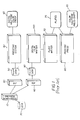
| |
| 10. | |
| 20. | Disk with |
| 30. | Raster image processor (RIP) for |
| 40. | Raster image processor (RIP) for |
| 43. | High resolution film scanner. |
| 50. | |
| 51. | Proofing and |
| 60. | Proofing |
| 65. | Digital |
| 70. | |
| 75. | |
| 80. | |
| 85. | Color halftone press- |
| 90. | Plate |
| 100. | |
| 110. | Dot-gain correction box for proofing |
| 111. | Dot-gain correction box for |
| 200. | |
| 210. | Blurred |
| 220. | |
| 230. | Local area averaged image |
| 240. | Lookup table |
| 250. | Threshold values |
| 260. | |
| 270. | Dot-gain adjusted |
| 280. | Off |
| 290. | On |
| 300. | Additional micro-pixel to add dot- |
| 310. | Deleted micro-pixel to subtract dot-gain |
Claims (13)
Priority Applications (2)
| Application Number | Priority Date | Filing Date | Title |
|---|---|---|---|
| US10/196,013 US6717601B2 (en) | 2002-07-16 | 2002-07-16 | Printing apparatus with dot-gain compensation using spatial filter |
| US10/714,315 US7400335B2 (en) | 2002-07-16 | 2003-11-14 | Method for printing a halftone digital image |
Applications Claiming Priority (1)
| Application Number | Priority Date | Filing Date | Title |
|---|---|---|---|
| US10/196,013 US6717601B2 (en) | 2002-07-16 | 2002-07-16 | Printing apparatus with dot-gain compensation using spatial filter |
Related Child Applications (1)
| Application Number | Title | Priority Date | Filing Date |
|---|---|---|---|
| US10/714,315 Continuation US7400335B2 (en) | 2002-07-16 | 2003-11-14 | Method for printing a halftone digital image |
Publications (2)
| Publication Number | Publication Date |
|---|---|
| US20040012647A1 US20040012647A1 (en) | 2004-01-22 |
| US6717601B2 true US6717601B2 (en) | 2004-04-06 |
Family
ID=30442754
Family Applications (2)
| Application Number | Title | Priority Date | Filing Date |
|---|---|---|---|
| US10/196,013 Expired - Fee Related US6717601B2 (en) | 2002-07-16 | 2002-07-16 | Printing apparatus with dot-gain compensation using spatial filter |
| US10/714,315 Expired - Fee Related US7400335B2 (en) | 2002-07-16 | 2003-11-14 | Method for printing a halftone digital image |
Family Applications After (1)
| Application Number | Title | Priority Date | Filing Date |
|---|---|---|---|
| US10/714,315 Expired - Fee Related US7400335B2 (en) | 2002-07-16 | 2003-11-14 | Method for printing a halftone digital image |
Country Status (1)
| Country | Link |
|---|---|
| US (2) | US6717601B2 (en) |
Cited By (6)
| Publication number | Priority date | Publication date | Assignee | Title |
|---|---|---|---|---|
| US20040085555A1 (en) * | 2002-09-09 | 2004-05-06 | Canon Kabushiki Kaisha | Image processing method and image output system |
| US6792864B2 (en) * | 2003-01-03 | 2004-09-21 | Eastman Kodak Company | Image file data equivalence algorithms respective to output devices |
| US20040247200A1 (en) * | 2003-06-06 | 2004-12-09 | Michael Hansen | Grey value correction method for binary image data |
| US20060119875A1 (en) * | 2004-12-03 | 2006-06-08 | Samsung Electronics Co., Ltd. | Print apparatus and print method |
| US20090262179A1 (en) * | 2008-04-22 | 2009-10-22 | Heidelberger Druckmaschinen Aktiengesellschaft | Method for reducing the area coverage of a printing plate |
| US20150015915A1 (en) * | 2013-07-09 | 2015-01-15 | Canon Kabushiki Kaisha | Image processing apparatus, image processing method, and storage medium |
Families Citing this family (11)
| Publication number | Priority date | Publication date | Assignee | Title |
|---|---|---|---|---|
| US6803933B1 (en) * | 2003-06-16 | 2004-10-12 | Hewlett-Packard Development Company, L.P. | Systems and methods for dot gain determination and dot gain based printing |
| EP1596575A3 (en) * | 2003-10-23 | 2010-03-10 | Agfa Graphics N.V. | Method for making a dot for dot proof |
| EP1766959A1 (en) * | 2004-05-05 | 2007-03-28 | Eastman Kodak Company | Color management of halftone prints |
| JP2006033064A (en) * | 2004-07-12 | 2006-02-02 | Konica Minolta Medical & Graphic Inc | Image forming method, and image forming apparatus |
| WO2008133629A1 (en) * | 2007-04-30 | 2008-11-06 | Hewlett-Packard Development Company, L.P. | Halftone printing with different screens |
| US7767383B2 (en) * | 2007-08-08 | 2010-08-03 | Roberts David H | Method of pre-exposing relief image printing plate |
| US8687236B2 (en) * | 2009-01-22 | 2014-04-01 | Hewlett-Packard Development Company, L.P. | Ink restriction determination |
| US9369608B2 (en) | 2010-12-13 | 2016-06-14 | Hewlett-Packard Industrial Printing Ltd | Printing methods and apparatus |
| ES2808686T3 (en) * | 2012-06-13 | 2021-03-01 | Xylo Tech Ag | Panel with decorative layer as well as procedure for printing plates |
| US8790864B2 (en) * | 2012-08-27 | 2014-07-29 | Kyle P. Baldwin | Method of improving print performance in flexographic printing plates |
| KR102388780B1 (en) | 2014-04-02 | 2022-04-19 | 에어다이 인텔렉츄얼 프로퍼티 엘엘씨 | Color management |
Citations (13)
| Publication number | Priority date | Publication date | Assignee | Title |
|---|---|---|---|---|
| US4630125A (en) | 1983-06-01 | 1986-12-16 | Xerox Corporation | Unscreening of stored digital halftone images |
| US5164742A (en) | 1989-12-18 | 1992-11-17 | Eastman Kodak Company | Thermal printer |
| US5208871A (en) | 1990-10-19 | 1993-05-04 | Xerox Corporation | Pixel quantization with adaptive error diffusion |
| US5250934A (en) | 1990-12-31 | 1993-10-05 | Xerox Corporation | Method and apparatus for thinning printed images |
| US5255085A (en) | 1991-10-25 | 1993-10-19 | Eastman Kodak Company | Adaptive technique for providing accurate tone reproduction control in an imaging system |
| US5258854A (en) | 1991-12-06 | 1993-11-02 | Xerox Corporation | Converting between write-white, write-black and neutral bitmaps |
| US5293539A (en) | 1991-10-25 | 1994-03-08 | Eastman Kodak Company | Method and apparatus for calibrating tone reproduction in a proofing system |
| US5483351A (en) | 1992-09-25 | 1996-01-09 | Xerox Corporation | Dilation of images without resolution conversion to compensate for printer characteristics |
| US5579044A (en) * | 1993-08-20 | 1996-11-26 | Intergraph Corporation | Digital proofing system |
| US5680485A (en) | 1994-12-19 | 1997-10-21 | Xerox Corporation | Method and apparatus employing erosion-based filter pairs for image mapping |
| US5721625A (en) * | 1994-03-18 | 1998-02-24 | Dainippon Screen Mfg. Co., Ltd. | Method and apparatus for generating halftone image considering spatial frequencies of original image |
| US6115140A (en) | 1998-07-28 | 2000-09-05 | Shira Computers Ltd. | Method and system for half tone color conversion |
| US6204874B1 (en) | 1998-05-07 | 2001-03-20 | Creo Products Inc. | Thermal platesetter and color proofer |
Family Cites Families (4)
| Publication number | Priority date | Publication date | Assignee | Title |
|---|---|---|---|---|
| US5309246A (en) * | 1991-09-18 | 1994-05-03 | Eastman Kodak Company | Technique for generating additional colors in a halftone color image through use of overlaid primary colored halftone dots of varying size |
| US6072588A (en) * | 1996-04-02 | 2000-06-06 | Fuji Photo Film Co., Ltd. | Method of generating proof data and method of generating proof |
| JP2001129986A (en) * | 1999-08-25 | 2001-05-15 | Mitsubishi Paper Mills Ltd | Digital prepress system |
| AU2002223445A1 (en) * | 2000-10-06 | 2002-04-15 | Best Gmbh | Method and device for proofing raster print data while maintaining the raster information |
-
2002
- 2002-07-16 US US10/196,013 patent/US6717601B2/en not_active Expired - Fee Related
-
2003
- 2003-11-14 US US10/714,315 patent/US7400335B2/en not_active Expired - Fee Related
Patent Citations (14)
| Publication number | Priority date | Publication date | Assignee | Title |
|---|---|---|---|---|
| US4630125A (en) | 1983-06-01 | 1986-12-16 | Xerox Corporation | Unscreening of stored digital halftone images |
| US5164742A (en) | 1989-12-18 | 1992-11-17 | Eastman Kodak Company | Thermal printer |
| US5208871A (en) | 1990-10-19 | 1993-05-04 | Xerox Corporation | Pixel quantization with adaptive error diffusion |
| US5250934A (en) | 1990-12-31 | 1993-10-05 | Xerox Corporation | Method and apparatus for thinning printed images |
| US5293539A (en) | 1991-10-25 | 1994-03-08 | Eastman Kodak Company | Method and apparatus for calibrating tone reproduction in a proofing system |
| US5255085A (en) | 1991-10-25 | 1993-10-19 | Eastman Kodak Company | Adaptive technique for providing accurate tone reproduction control in an imaging system |
| US5258854A (en) | 1991-12-06 | 1993-11-02 | Xerox Corporation | Converting between write-white, write-black and neutral bitmaps |
| US5483351A (en) | 1992-09-25 | 1996-01-09 | Xerox Corporation | Dilation of images without resolution conversion to compensate for printer characteristics |
| US5579044A (en) * | 1993-08-20 | 1996-11-26 | Intergraph Corporation | Digital proofing system |
| US5767887A (en) * | 1993-08-20 | 1998-06-16 | Optronics International Corporation | System for plotting graphic Images |
| US5721625A (en) * | 1994-03-18 | 1998-02-24 | Dainippon Screen Mfg. Co., Ltd. | Method and apparatus for generating halftone image considering spatial frequencies of original image |
| US5680485A (en) | 1994-12-19 | 1997-10-21 | Xerox Corporation | Method and apparatus employing erosion-based filter pairs for image mapping |
| US6204874B1 (en) | 1998-05-07 | 2001-03-20 | Creo Products Inc. | Thermal platesetter and color proofer |
| US6115140A (en) | 1998-07-28 | 2000-09-05 | Shira Computers Ltd. | Method and system for half tone color conversion |
Cited By (11)
| Publication number | Priority date | Publication date | Assignee | Title |
|---|---|---|---|---|
| US20040085555A1 (en) * | 2002-09-09 | 2004-05-06 | Canon Kabushiki Kaisha | Image processing method and image output system |
| US7864363B2 (en) * | 2002-09-09 | 2011-01-04 | Canon Kabushiki Kaisha | Image processing method and image output system |
| US6792864B2 (en) * | 2003-01-03 | 2004-09-21 | Eastman Kodak Company | Image file data equivalence algorithms respective to output devices |
| US20040247200A1 (en) * | 2003-06-06 | 2004-12-09 | Michael Hansen | Grey value correction method for binary image data |
| US7933466B2 (en) * | 2003-06-06 | 2011-04-26 | Heidelberger Druckmaschinen Ag | Grey value correction method for binary image data |
| US20060119875A1 (en) * | 2004-12-03 | 2006-06-08 | Samsung Electronics Co., Ltd. | Print apparatus and print method |
| US7675642B2 (en) * | 2004-12-03 | 2010-03-09 | Samsung Electronics Co., Ltd. | Print apparatus and print method |
| US20090262179A1 (en) * | 2008-04-22 | 2009-10-22 | Heidelberger Druckmaschinen Aktiengesellschaft | Method for reducing the area coverage of a printing plate |
| US8300275B2 (en) * | 2008-04-22 | 2012-10-30 | Heidelberger Druckmaschinen Ag | Method for reducing the area coverage of a printing plate |
| US20150015915A1 (en) * | 2013-07-09 | 2015-01-15 | Canon Kabushiki Kaisha | Image processing apparatus, image processing method, and storage medium |
| US9208417B2 (en) * | 2013-07-09 | 2015-12-08 | Canon Kabushiki Kaisha | Image processing apparatus, recording method, and storage medium for outputting image data expressing halftone dots |
Also Published As
| Publication number | Publication date |
|---|---|
| US20040012647A1 (en) | 2004-01-22 |
| US7400335B2 (en) | 2008-07-15 |
| US20040095592A1 (en) | 2004-05-20 |
Similar Documents
| Publication | Publication Date | Title |
|---|---|---|
| US6717601B2 (en) | Printing apparatus with dot-gain compensation using spatial filter | |
| US7826097B2 (en) | Asymmetrical digital filters for dot gain adjustments | |
| US6775029B1 (en) | Method for efficient calibration of printing devices | |
| US20110317222A1 (en) | Methods and apparatus for dynamically soft proofing halftone images | |
| US20060204089A1 (en) | Method and apparatus for compensating for DOT gain in stochastic printing | |
| EP1366618B1 (en) | Error diffusion with partial dots method and system | |
| US6525838B1 (en) | Color image processing apparatus and recording medium | |
| EP1443751B1 (en) | A method of adjusting color in a color proof | |
| US6842268B1 (en) | Printing of digital color images with locally adjusted half-toning | |
| US7050200B2 (en) | Lookup table for adjusting dot-gain on bitmap files based on average number of dots | |
| US7280259B2 (en) | Method for printing a color proof using a spatial filter | |
| US7245400B2 (en) | Method and device for proofing raster print data while maintaining the raster information | |
| US6863360B2 (en) | Method for adjusting dot-gain for a halftone binary bitmap | |
| US6893105B2 (en) | Method for printing an image from a halftone binary bitmap using multiple exposures | |
| US6771390B1 (en) | Method for modifying the size of line elements | |
| US8730525B2 (en) | Method and device for proofing raster print data while maintaining the raster information | |
| Kuznetsov et al. | Optimal image encoding for hard copy production and method of its efficiency estimation | |
| JPH09270930A (en) | Method for generating print proof | |
| Bandyopadhyay | Effect of Screen Ruling and Screen Shape on Image Quality |
Legal Events
| Date | Code | Title | Description |
|---|---|---|---|
| AS | Assignment |
Owner name: EASTMAN KODAK COMPANY, NEW YORK Free format text: ASSIGNMENT OF ASSIGNORS INTEREST;ASSIGNOR:SANGER, KURT M.;REEL/FRAME:013123/0022 Effective date: 20020716 |
|
| FEPP | Fee payment procedure |
Free format text: PAYOR NUMBER ASSIGNED (ORIGINAL EVENT CODE: ASPN); ENTITY STATUS OF PATENT OWNER: LARGE ENTITY |
|
| FPAY | Fee payment |
Year of fee payment: 4 |
|
| FPAY | Fee payment |
Year of fee payment: 8 |
|
| AS | Assignment |
Owner name: CITICORP NORTH AMERICA, INC., AS AGENT, NEW YORK Free format text: SECURITY INTEREST;ASSIGNORS:EASTMAN KODAK COMPANY;PAKON, INC.;REEL/FRAME:028201/0420 Effective date: 20120215 |
|
| AS | Assignment |
Owner name: WILMINGTON TRUST, NATIONAL ASSOCIATION, AS AGENT, MINNESOTA Free format text: PATENT SECURITY AGREEMENT;ASSIGNORS:EASTMAN KODAK COMPANY;PAKON, INC.;REEL/FRAME:030122/0235 Effective date: 20130322 Owner name: WILMINGTON TRUST, NATIONAL ASSOCIATION, AS AGENT, Free format text: PATENT SECURITY AGREEMENT;ASSIGNORS:EASTMAN KODAK COMPANY;PAKON, INC.;REEL/FRAME:030122/0235 Effective date: 20130322 |
|
| AS | Assignment |
Owner name: BANK OF AMERICA N.A., AS AGENT, MASSACHUSETTS Free format text: INTELLECTUAL PROPERTY SECURITY AGREEMENT (ABL);ASSIGNORS:EASTMAN KODAK COMPANY;FAR EAST DEVELOPMENT LTD.;FPC INC.;AND OTHERS;REEL/FRAME:031162/0117 Effective date: 20130903 Owner name: JPMORGAN CHASE BANK, N.A., AS ADMINISTRATIVE, DELAWARE Free format text: INTELLECTUAL PROPERTY SECURITY AGREEMENT (FIRST LIEN);ASSIGNORS:EASTMAN KODAK COMPANY;FAR EAST DEVELOPMENT LTD.;FPC INC.;AND OTHERS;REEL/FRAME:031158/0001 Effective date: 20130903 Owner name: BARCLAYS BANK PLC, AS ADMINISTRATIVE AGENT, NEW YORK Free format text: INTELLECTUAL PROPERTY SECURITY AGREEMENT (SECOND LIEN);ASSIGNORS:EASTMAN KODAK COMPANY;FAR EAST DEVELOPMENT LTD.;FPC INC.;AND OTHERS;REEL/FRAME:031159/0001 Effective date: 20130903 Owner name: EASTMAN KODAK COMPANY, NEW YORK Free format text: RELEASE OF SECURITY INTEREST IN PATENTS;ASSIGNORS:CITICORP NORTH AMERICA, INC., AS SENIOR DIP AGENT;WILMINGTON TRUST, NATIONAL ASSOCIATION, AS JUNIOR DIP AGENT;REEL/FRAME:031157/0451 Effective date: 20130903 Owner name: BARCLAYS BANK PLC, AS ADMINISTRATIVE AGENT, NEW YO Free format text: INTELLECTUAL PROPERTY SECURITY AGREEMENT (SECOND LIEN);ASSIGNORS:EASTMAN KODAK COMPANY;FAR EAST DEVELOPMENT LTD.;FPC INC.;AND OTHERS;REEL/FRAME:031159/0001 Effective date: 20130903 Owner name: PAKON, INC., NEW YORK Free format text: RELEASE OF SECURITY INTEREST IN PATENTS;ASSIGNORS:CITICORP NORTH AMERICA, INC., AS SENIOR DIP AGENT;WILMINGTON TRUST, NATIONAL ASSOCIATION, AS JUNIOR DIP AGENT;REEL/FRAME:031157/0451 Effective date: 20130903 Owner name: JPMORGAN CHASE BANK, N.A., AS ADMINISTRATIVE, DELA Free format text: INTELLECTUAL PROPERTY SECURITY AGREEMENT (FIRST LIEN);ASSIGNORS:EASTMAN KODAK COMPANY;FAR EAST DEVELOPMENT LTD.;FPC INC.;AND OTHERS;REEL/FRAME:031158/0001 Effective date: 20130903 |
|
| REMI | Maintenance fee reminder mailed | ||
| LAPS | Lapse for failure to pay maintenance fees | ||
| STCH | Information on status: patent discontinuation |
Free format text: PATENT EXPIRED DUE TO NONPAYMENT OF MAINTENANCE FEES UNDER 37 CFR 1.362 |
|
| FP | Lapsed due to failure to pay maintenance fee |
Effective date: 20160406 |
|
| AS | Assignment |
Owner name: FPC, INC., NEW YORK Free format text: RELEASE BY SECURED PARTY;ASSIGNOR:JP MORGAN CHASE BANK, N.A., AS ADMINISTRATIVE AGENT;REEL/FRAME:049814/0001 Effective date: 20190617 Owner name: QUALEX, INC., NEW YORK Free format text: RELEASE BY SECURED PARTY;ASSIGNOR:JP MORGAN CHASE BANK, N.A., AS ADMINISTRATIVE AGENT;REEL/FRAME:049814/0001 Effective date: 20190617 Owner name: KODAK AMERICAS, LTD., NEW YORK Free format text: RELEASE BY SECURED PARTY;ASSIGNOR:JP MORGAN CHASE BANK, N.A., AS ADMINISTRATIVE AGENT;REEL/FRAME:049814/0001 Effective date: 20190617 Owner name: KODAK IMAGING NETWORK, INC., NEW YORK Free format text: RELEASE BY SECURED PARTY;ASSIGNOR:JP MORGAN CHASE BANK, N.A., AS ADMINISTRATIVE AGENT;REEL/FRAME:049814/0001 Effective date: 20190617 Owner name: KODAK (NEAR EAST), INC., NEW YORK Free format text: RELEASE BY SECURED PARTY;ASSIGNOR:JP MORGAN CHASE BANK, N.A., AS ADMINISTRATIVE AGENT;REEL/FRAME:049814/0001 Effective date: 20190617 Owner name: CREO MANUFACTURING AMERICA LLC, NEW YORK Free format text: RELEASE BY SECURED PARTY;ASSIGNOR:JP MORGAN CHASE BANK, N.A., AS ADMINISTRATIVE AGENT;REEL/FRAME:049814/0001 Effective date: 20190617 Owner name: FAR EAST DEVELOPMENT LTD., NEW YORK Free format text: RELEASE BY SECURED PARTY;ASSIGNOR:JP MORGAN CHASE BANK, N.A., AS ADMINISTRATIVE AGENT;REEL/FRAME:049814/0001 Effective date: 20190617 Owner name: KODAK AVIATION LEASING LLC, NEW YORK Free format text: RELEASE BY SECURED PARTY;ASSIGNOR:JP MORGAN CHASE BANK, N.A., AS ADMINISTRATIVE AGENT;REEL/FRAME:049814/0001 Effective date: 20190617 Owner name: KODAK PORTUGUESA LIMITED, NEW YORK Free format text: RELEASE BY SECURED PARTY;ASSIGNOR:JP MORGAN CHASE BANK, N.A., AS ADMINISTRATIVE AGENT;REEL/FRAME:049814/0001 Effective date: 20190617 Owner name: LASER PACIFIC MEDIA CORPORATION, NEW YORK Free format text: RELEASE BY SECURED PARTY;ASSIGNOR:JP MORGAN CHASE BANK, N.A., AS ADMINISTRATIVE AGENT;REEL/FRAME:049814/0001 Effective date: 20190617 Owner name: KODAK PHILIPPINES, LTD., NEW YORK Free format text: RELEASE BY SECURED PARTY;ASSIGNOR:JP MORGAN CHASE BANK, N.A., AS ADMINISTRATIVE AGENT;REEL/FRAME:049814/0001 Effective date: 20190617 Owner name: PAKON, INC., NEW YORK Free format text: RELEASE BY SECURED PARTY;ASSIGNOR:JP MORGAN CHASE BANK, N.A., AS ADMINISTRATIVE AGENT;REEL/FRAME:049814/0001 Effective date: 20190617 Owner name: NPEC, INC., NEW YORK Free format text: RELEASE BY SECURED PARTY;ASSIGNOR:JP MORGAN CHASE BANK, N.A., AS ADMINISTRATIVE AGENT;REEL/FRAME:049814/0001 Effective date: 20190617 Owner name: EASTMAN KODAK COMPANY, NEW YORK Free format text: RELEASE BY SECURED PARTY;ASSIGNOR:JP MORGAN CHASE BANK, N.A., AS ADMINISTRATIVE AGENT;REEL/FRAME:049814/0001 Effective date: 20190617 Owner name: KODAK REALTY, INC., NEW YORK Free format text: RELEASE BY SECURED PARTY;ASSIGNOR:JP MORGAN CHASE BANK, N.A., AS ADMINISTRATIVE AGENT;REEL/FRAME:049814/0001 Effective date: 20190617 |
|
| AS | Assignment |
Owner name: KODAK AMERICAS LTD., NEW YORK Free format text: RELEASE BY SECURED PARTY;ASSIGNOR:BARCLAYS BANK PLC;REEL/FRAME:052773/0001 Effective date: 20170202 Owner name: KODAK PHILIPPINES LTD., NEW YORK Free format text: RELEASE BY SECURED PARTY;ASSIGNOR:BARCLAYS BANK PLC;REEL/FRAME:052773/0001 Effective date: 20170202 Owner name: NPEC INC., NEW YORK Free format text: RELEASE BY SECURED PARTY;ASSIGNOR:BARCLAYS BANK PLC;REEL/FRAME:052773/0001 Effective date: 20170202 Owner name: LASER PACIFIC MEDIA CORPORATION, NEW YORK Free format text: RELEASE BY SECURED PARTY;ASSIGNOR:BARCLAYS BANK PLC;REEL/FRAME:052773/0001 Effective date: 20170202 Owner name: KODAK REALTY INC., NEW YORK Free format text: RELEASE BY SECURED PARTY;ASSIGNOR:BARCLAYS BANK PLC;REEL/FRAME:052773/0001 Effective date: 20170202 Owner name: QUALEX INC., NEW YORK Free format text: RELEASE BY SECURED PARTY;ASSIGNOR:BARCLAYS BANK PLC;REEL/FRAME:052773/0001 Effective date: 20170202 Owner name: FPC INC., NEW YORK Free format text: RELEASE BY SECURED PARTY;ASSIGNOR:BARCLAYS BANK PLC;REEL/FRAME:052773/0001 Effective date: 20170202 Owner name: EASTMAN KODAK COMPANY, NEW YORK Free format text: RELEASE BY SECURED PARTY;ASSIGNOR:BARCLAYS BANK PLC;REEL/FRAME:052773/0001 Effective date: 20170202 Owner name: KODAK (NEAR EAST) INC., NEW YORK Free format text: RELEASE BY SECURED PARTY;ASSIGNOR:BARCLAYS BANK PLC;REEL/FRAME:052773/0001 Effective date: 20170202 Owner name: FAR EAST DEVELOPMENT LTD., NEW YORK Free format text: RELEASE BY SECURED PARTY;ASSIGNOR:BARCLAYS BANK PLC;REEL/FRAME:052773/0001 Effective date: 20170202 |