US6722754B1 - Printer carriage jam detector using sensed motor current - Google Patents

Printer carriage jam detector using sensed motor current Download PDF

Info

Publication number
US6722754B1
US6722754B1 US10/336,974 US33697403A US6722754B1 US 6722754 B1 US6722754 B1 US 6722754B1 US 33697403 A US33697403 A US 33697403A US 6722754 B1 US6722754 B1 US 6722754B1
Authority
US
United States
Prior art keywords
stepper motor
carriage
voltage waveform
time
winding
Prior art date
Legal status (The legal status is an assumption and is not a legal conclusion. Google has not performed a legal analysis and makes no representation as to the accuracy of the status listed.)
Expired - Lifetime, expires
Application number
US10/336,974
Inventor
Robert Delaney
James R. Del Signore
Kathleen Maginnity
John G. Mitchell
Thomas Parent
Current Assignee (The listed assignees may be inaccurate. Google has not performed a legal analysis and makes no representation or warranty as to the accuracy of the list.)
COGNITIVETPG LLC
CTPG OPERATING LLC
Original Assignee
Axiohm Transaction Solutions Inc
Priority date (The priority date is an assumption and is not a legal conclusion. Google has not performed a legal analysis and makes no representation as to the accuracy of the date listed.)
Filing date
Publication date
Application filed by Axiohm Transaction Solutions Inc filed Critical Axiohm Transaction Solutions Inc
Priority to US10/336,974 priority Critical patent/US6722754B1/en
Assigned to AXIOHM TRANSACTION SOLUTIONS, INC. reassignment AXIOHM TRANSACTION SOLUTIONS, INC. ASSIGNMENT OF ASSIGNORS INTEREST (SEE DOCUMENT FOR DETAILS). Assignors: PARENT, THOMAS, DEL SIGNORE, JAMES R., DELANEY, ROBERT, MAGINNITY, KATHLEEN, MITCHELL, JOHN G.
Application granted granted Critical
Publication of US6722754B1 publication Critical patent/US6722754B1/en
Assigned to ATSI HOLDINGS, INC. reassignment ATSI HOLDINGS, INC. CHANGE OF NAME (SEE DOCUMENT FOR DETAILS). Assignors: AXIOHM TRANSACTION SOLUTIONS, INC.
Assigned to COGNITIVETPG, LLC reassignment COGNITIVETPG, LLC ASSIGNMENT OF ASSIGNORS INTEREST (SEE DOCUMENT FOR DETAILS). Assignors: ATSI HOLDINGS, INC.
Assigned to TOMPKINS TRUST COMPANY reassignment TOMPKINS TRUST COMPANY SECURITY AGREEMENT Assignors: COGNITIVETPG, LLC F/K/A CTPG OPERATING, LLC
Assigned to CTPG OPERATING, LLC reassignment CTPG OPERATING, LLC ASSIGNMENT OF ASSIGNORS INTEREST (SEE DOCUMENT FOR DETAILS). Assignors: COGNTIVE TPG, LLC
Assigned to COGNITIVETPG, LLC reassignment COGNITIVETPG, LLC CHANGE OF NAME (SEE DOCUMENT FOR DETAILS). Assignors: CTPG OPERATING, LLC
Assigned to PINE STREET CAPITAL PARTNERS II, LP reassignment PINE STREET CAPITAL PARTNERS II, LP SECURITY AGREEMENT Assignors: COGNITIVETPG, LLC
Assigned to COGNITIVETPG, LLC reassignment COGNITIVETPG, LLC RELEASE BY SECURED PARTY (SEE DOCUMENT FOR DETAILS). Assignors: PINE STREET CAPITAL PARTNERS II, LP
Adjusted expiration legal-status Critical
Expired - Lifetime legal-status Critical Current

Links

Images

Classifications

    • BPERFORMING OPERATIONS; TRANSPORTING
    • B41PRINTING; LINING MACHINES; TYPEWRITERS; STAMPS
    • B41JTYPEWRITERS; SELECTIVE PRINTING MECHANISMS, i.e. MECHANISMS PRINTING OTHERWISE THAN FROM A FORME; CORRECTION OF TYPOGRAPHICAL ERRORS
    • B41J11/00Devices or arrangements  of selective printing mechanisms, e.g. ink-jet printers or thermal printers, for supporting or handling copy material in sheet or web form
    • B41J11/006Means for preventing paper jams or for facilitating their removal
    • BPERFORMING OPERATIONS; TRANSPORTING
    • B41PRINTING; LINING MACHINES; TYPEWRITERS; STAMPS
    • B41JTYPEWRITERS; SELECTIVE PRINTING MECHANISMS, i.e. MECHANISMS PRINTING OTHERWISE THAN FROM A FORME; CORRECTION OF TYPOGRAPHICAL ERRORS
    • B41J19/00Character- or line-spacing mechanisms
    • B41J19/18Character-spacing or back-spacing mechanisms; Carriage return or release devices therefor
    • B41J19/20Positive-feed character-spacing mechanisms
    • B41J19/202Drive control means for carriage movement
    • B41J19/205Position or speed detectors therefor
    • BPERFORMING OPERATIONS; TRANSPORTING
    • B41PRINTING; LINING MACHINES; TYPEWRITERS; STAMPS
    • B41JTYPEWRITERS; SELECTIVE PRINTING MECHANISMS, i.e. MECHANISMS PRINTING OTHERWISE THAN FROM A FORME; CORRECTION OF TYPOGRAPHICAL ERRORS
    • B41J29/00Details of, or accessories for, typewriters or selective printing mechanisms not otherwise provided for
    • B41J29/46Applications of alarms, e.g. responsive to approach of end of line

Definitions

  • This invention relates to jam detection in a printer and, more particularly, to detecting carriage jams by sensing current in a carriage drive stepper motor.
  • Detecting paper jams in a printer is important for several reasons. First, continued application of driving force to the carriage drive motor after a paper jam may cause physical damage to the print head, its associated mounting structure, or other carriage hardware. Also, paper may be bunched or compacted to the point where its removal is difficult without disassembling the print head or another part of the carriage structure. An improperly detected jam may result in the destruction of a payment document, such as the only personal check a customer may have. In addition, data sent to the printer for printing may be discarded and possibly irretrievably lost if the printer electronics are not notified on a timely basis that the data has not been successfully printed.
  • stepper motors to drive their carriages.
  • POS point-of-sale
  • stepper motors typically, only a subset of the multiple stepper motor windings are driven simultaneously. This allows current induced in other, undriven windings to be monitored and the instantaneous status of the stepper motor movement deduced.
  • the system of the present invention monitors phase current to derive a logic signal indicating to the printer controller that a carriage jam has occurred.
  • the inventive system monitors the current waveform of a driven winding of the carriage stepper motor.
  • An amplifier and a comparator are used to digitize the analog voltage waveform from across a sense resistor in the stepper motor's drive line.
  • An operational amplifier having its gain optimized for the application is used to ensure that digitization of the current waveform corresponds accurately with known values in a digital count table.
  • stepper motor drive system is disclosed in U.S. Pat. No. 5,367,239 for PRINTER CARRIER DRIVING METHOD, issued Nov. 22, 1994 to Tsuyoshi Matsushita, et al. MATSUSHITA, et al., teaches a stepper motor drive where improved control of acceleration and deceleration is achieved from a single-voltage power source. Stored data corresponding to acceleration, constant speed printing, and deceleration are used to generate a current reference voltage. There is, however, no teaching of jam detection through monitoring of either current or voltage supplied to the stepper motor.
  • the inventive system monitors current in a single winding of the stepper motor at the commutation time of another winding to derive highly accurate jam detection (i.e., stalled carriage) information.
  • U.S. Pat. No. 5,431,502 for CARRIAGE MOTOR CONTROLLER FOR PRINTER issued Jul. 11, 1995 to Yasunori Orii, et al.
  • ORII, et al. use a rotary encoder to generate position data and generate acceleration/deceleration commands based upon both absolute position data from the encoder as well as from stored motor characteristic data.
  • the stored motor characteristic data is periodically updated to reflect the current operating characteristics of the stepper motor.
  • the inventive system develops a jam signal from the A to D conversion of a voltage signal obtained from a low value series resistor in one of the stepper motor winding drive lines.
  • An operational amplifier having a carefully selected gain functions to provide a signal indicative of operational current levels that can be read by commercial A/D converters.
  • the inventive system monitors the current waveshape in the “Phase A” winding at the time when the “Phase B” commutation occurs. By selecting this time window, the accuracy of the detection is greatly enhanced.
  • the present invention is a method for monitoring the current waveshape in a first winding of a stepper motor at or near the time when a second winding of the stepper motor commutates.
  • the current waveshape is received from a low-value sensing resistor, typically within an integrated circuit stepper motor driver device. Changes in the current waveshape during this time window may be interpreted and accurate deductions may be made concerning the loading of the stepper motor.
  • the stepper motor is the drive motor for a printer carriage
  • the loading information may be used to detect a paper jam, similar problem, or reference position in the printer carriage. No external monitoring sensor is required, nor is there any need for traditional comb or similar look-through structures for use in combination with a light source and sensor for detecting carriage jams.
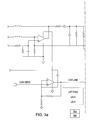
  • FIGS. 1 a and 1 b is a schematic diagram of the A/D converter showing the application of the CAR_JAM signal
  • FIG. 2 is a schematic diagram of a portion of the stepper motor controller showing the origin of the CAR_SENSE signal
  • FIGS. 3 a and 3 b is a schematic diagram showing the generation of the CAR_JAM signal from the CAR_SENSE signal;
  • FIG. 4 is a graph showing digital count error vs. the A/D input voltage
  • FIG. 5 a is a graph showing the relationship between motor phase voltage and the current waveform during normal operation.
  • FIG. 5 b is a graph showing the relationship between motor phase voltage and the current waveform under a carriage jam condition.
  • the present invention features a novel way of monitoring winding current in a stepper motor used as a carriage drive motor in a printer so as to detect a printer carriage jam.
  • the inventive method utilizes no external mechanical or electrical components.
  • the inventive method relies on detecting a significant (i.e., measurable) change in at least one significant feature of the current waveform in at least one winding of the carriage drive stepper motor.
  • FIG. 1 there is shown a schematic diagram 100 of a portion of the control electronics used in a typical small, desktop printer.
  • a new carriage jam (CAR_JAM) signal 102 is developed to replace a jam detect signal previously generated by a typical light source/sensor apparatus of the prior art. The generation of the CAR_JAM signal is described in detail hereinbelow.
  • CAR_JAM signal 102 is applied to channel 7 of an A/D converter, such as National Semiconductor ADC08388 8 channel A/D converter, which converts the selected analog input signal into digital count from 0 to 256 for the controlling microprocessor to read.
  • A/D converter such as National Semiconductor ADC08388 8 channel A/D converter
  • the stepper motor drive circuit 202 is typically a dual full-bridge PWM driver chip such as one of the Allegro Micro Systems 291x family of chips. It will be recognized by those of skill in the art that a wide variety of similar devices from other manufacturers is available in the marketplace; any of these device could be utilized to perform the functions of the Allegro Type 2916 chip chosen for purposes of disclosure.
  • a low-value internal sense resistor 204 located in series with the Phase 1 current output. The value of internal sense resistor 204 is approximately 0.8 ohms, in the 2916 chip.
  • the voltage across resistor 204 is provided at an output pin of the Allegro 2916 chip as signal “Sense 1 ”. This signal 206 provided on the sense 1 output pin is called CAR_SENS.
  • An op-amp feedback resister R f is chosen to be approximately 4750 ohms.
  • An op-amp input resister R i is chosen to be approximately 1000 ohms.
  • the A/D reference voltage is chosen to be approximately 2.5 volts with a tolerance of approximately ⁇ 0.005 volt.
  • the maximum phase current is chosen to be 500 ma.
  • the input phase current range may be specified and linearized:
  • Vo t Im t ⁇ Rs ⁇ ( Rf Ri + 1 )
  • CNT t [ Im t ⁇ Rs ⁇ ( Rf Ri + 1 ) Vref ] ⁇ CNT max
  • the total error count is, therefore:
  • the digital count and error vs. the A/D input voltage may calculated as shown in TABLE I, below.
  • a first drive signal 502 (Phase A) is applied to a first independent winding of a stepper motor (not shown).
  • a second drive signal 504 (Phase B) is applied to a second independent winding.
  • Drive signal 504 is applied at a later time than drive signal 502 . This timing is typical of how stepper motors are driven. While only two drive signals have been shown for purposes of disclosure, it will be recognized by those of skill in the stepper motor arts that additional drive signals and sequences are commonly used in stepper motor arrangements.
  • the time at which a drive signal is applied to a stepper motor winding is known as commutation time.
  • the time of commutation of the second drive signal 504 is of particular interest. This time has been identified as reference number 506 .
  • the sense voltage developed across the sense resistor in series with the first stepper motor winding is shown at 508 a and 508 b in FIGS. 5 a and 5 b , respectively.
  • the sense voltage 508 a at time 506 is approximately 1.0 volt.
  • the sense voltage 508 b at time 506 is approximately 1.22 volts and greater than the four percent error predicted for normal operations.
  • Phase A current waveform at the commutation of Phase B has been chosen as the waveform feature of interest for making a jammed condition determination, other features of the current waveform could also be used to satisfy a particular operating requirement.

Abstract

There is provided a method for monitoring paper or other jams of a carriage in a printer by monitoring the current waveshape in a first winding of a stepper motor at or near the time when a second winding of the stepper motor commutates. The current waveshape is received from a low-value sensing resistor, typically within an integrated circuit stepper motor driver device. Changes in the current waveshape during this time window may be interpreted and accurate deductions may be made concerning the loading of the stepper motor. In the case where the stepper motor is the drive motor for a printer carriage, the loading information may be used to detect a paper jam or similar problem in the printer carriage.

Description

FIELD OF THE INVENTION
This invention relates to jam detection in a printer and, more particularly, to detecting carriage jams by sensing current in a carriage drive stepper motor.
BACKGROUND OF INVENTION
Detecting paper jams in a printer is important for several reasons. First, continued application of driving force to the carriage drive motor after a paper jam may cause physical damage to the print head, its associated mounting structure, or other carriage hardware. Also, paper may be bunched or compacted to the point where its removal is difficult without disassembling the print head or another part of the carriage structure. An improperly detected jam may result in the destruction of a payment document, such as the only personal check a customer may have. In addition, data sent to the printer for printing may be discarded and possibly irretrievably lost if the printer electronics are not notified on a timely basis that the data has not been successfully printed.
Traditionally, paper jams near the print head carriage in a printer have been detected using some combination of interruptive sensors (i.e., see-through sensors) and comb strips. These implementations require additional mechanical hardware as well as extra electrical circuitry. Extra hardware in the carriage area not only adds cost and takes up valuable space within the printer, but it may contribute to paper jams in the carriage area by its very presence. Typical jam detection hardware, monitoring electronics and software are taught in U.S. Pat. No. 5,074,690 for PRINT HEAD CARRIAGE HOMING SYSTEM, issued Dec. 24, 1991 to James R. Del Signore, II, et al.
Many small, low-cost printers such as those used in point-of-sale (POS) checkout stations use stepper motors to drive their carriages. Typically, only a subset of the multiple stepper motor windings are driven simultaneously. This allows current induced in other, undriven windings to be monitored and the instantaneous status of the stepper motor movement deduced. Monitoring electrical current provided to a motor, whether stepper, DC, AC, etc., has long been used as a technique to deduce the motional status of the motor.
U.S. Pat. No. 4,383,209 for CONTROL SYSTEM FOR TRANSDUCER POSITIONING MOTOR, issued May 10, 1983 to Martyn A. Lewis, teaches a control system for a stepper motor in which both voltage and current are sensed in a closed-loop controller. The thrust of the LEWIS circuit, however, is to enhance the positional accuracy of a transducer such as a read head in a disk drive. Both a constant voltage and a constant current source are provided with seamless switching, while coarse seeking the constant current source provided the motor drive. During fine seeking of the track position, the constant voltage source provides the motor drive. LEWIS, however, teaches no monitoring of either current or voltage to determine a stalled condition such as would be experienced during a carriage jam in a printer.
The system of the present invention monitors phase current to derive a logic signal indicating to the printer controller that a carriage jam has occurred.
U.S. Pat. No. 5,032,781 for METHOD AND CIRCUIT FOR OPERATING A STEPPER MOTOR, issued Jul. 16, 1991 to Klaus Kronenberg, teaches another stepper motor controller wherein an induced voltage in a winding, which is not required at the time to produce a propulsive force, is evaluated and a stopped motor condition detected. KRONENBERG stores the instantaneous position of the motor in memory for later recovery.
In contradistinction, the inventive system monitors the current waveform of a driven winding of the carriage stepper motor. An amplifier and a comparator are used to digitize the analog voltage waveform from across a sense resistor in the stepper motor's drive line. An operational amplifier having its gain optimized for the application is used to ensure that digitization of the current waveform corresponds accurately with known values in a digital count table.
U.S. Pat. No. 5,074,690 for PRINT HEAD CARRIAGE HOMING SYSTEM, issued Dec. 24, 1991, to James R. Del Signore II, et al., teaches using a ribbon timing strip and a sensor for printer jam detection. No current sensing in a stepper motor winding is disclosed.
Another stepper motor drive system is disclosed in U.S. Pat. No. 5,367,239 for PRINTER CARRIER DRIVING METHOD, issued Nov. 22, 1994 to Tsuyoshi Matsushita, et al. MATSUSHITA, et al., teaches a stepper motor drive where improved control of acceleration and deceleration is achieved from a single-voltage power source. Stored data corresponding to acceleration, constant speed printing, and deceleration are used to generate a current reference voltage. There is, however, no teaching of jam detection through monitoring of either current or voltage supplied to the stepper motor.
The inventive system, on the other hand, monitors current in a single winding of the stepper motor at the commutation time of another winding to derive highly accurate jam detection (i.e., stalled carriage) information.
U.S. Pat. No. 5,431,502 for CARRIAGE MOTOR CONTROLLER FOR PRINTER, issued Jul. 11, 1995 to Yasunori Orii, et al., teaches yet another stepper motor controller for a printer carriage. ORII, et al. use a rotary encoder to generate position data and generate acceleration/deceleration commands based upon both absolute position data from the encoder as well as from stored motor characteristic data. The stored motor characteristic data is periodically updated to reflect the current operating characteristics of the stepper motor. There is, however, no teaching of carriage jam detection through voltage and/or current monitoring.
The inventive system, on the other hand, develops a jam signal from the A to D conversion of a voltage signal obtained from a low value series resistor in one of the stepper motor winding drive lines. An operational amplifier having a carefully selected gain functions to provide a signal indicative of operational current levels that can be read by commercial A/D converters. The inventive system monitors the current waveshape in the “Phase A” winding at the time when the “Phase B” commutation occurs. By selecting this time window, the accuracy of the detection is greatly enhanced.
U.S. Pat. No. 6,150,789 for STEPPER MOTOR CONTROL, issued Nov. 21, 2000 to Robert Pulford, Jr., teaches sensing current in one winding of a stepper motor for control purposes. PULFORD discloses no sampling of current specifically during the commutation of a different motor phase winding. Neither does PULFORD specifically teach jam detection in a printer carriage.
None of these patents taken individually or in any combination teaches or suggests the carriage jam detection method of the present invention.
It is therefore an object of the invention to provide a carriage jam detection method for use in a printer which requires neither a comb nor flag and sensor mechanism to reliably detect carriage jams.
It is a further object of the invention to provide a carriage jam detection method for use in a printer which monitors current in a single, active winding of a stepper motor driving the printer carriage.
It is an additional object of the invention to provide a carriage jam detection method for use in a printer which monitors current in a first stepper motor winding at approximately, but not limited to, the time that a second winding of the stepper motor commutates.
It is another object of the invention to provide a carriage jam detection method for use in a printer which does not necessarily require an additional, external motion sensor.
It is a further object of the invention to provide a carriage jam detection method for use in a printer which utilizes a small resistor in the motor drive circuit as a sensing resistor to obtain a voltage waveform representative of the instantaneous motor winding current.
SUMMARY OF INVENTION
The present invention is a method for monitoring the current waveshape in a first winding of a stepper motor at or near the time when a second winding of the stepper motor commutates. The current waveshape is received from a low-value sensing resistor, typically within an integrated circuit stepper motor driver device. Changes in the current waveshape during this time window may be interpreted and accurate deductions may be made concerning the loading of the stepper motor. In the case where the stepper motor is the drive motor for a printer carriage, the loading information may be used to detect a paper jam, similar problem, or reference position in the printer carriage. No external monitoring sensor is required, nor is there any need for traditional comb or similar look-through structures for use in combination with a light source and sensor for detecting carriage jams.
BRIEF DESCRIPTION OF THE DRAWINGS
A complete understanding of the present invention may be obtained by reference to the accompanying drawings, when taken in conjunction with the detail description thereof and in which:
FIGS. 1a and 1 b is a schematic diagram of the A/D converter showing the application of the CAR_JAM signal;
FIG. 2 is a schematic diagram of a portion of the stepper motor controller showing the origin of the CAR_SENSE signal;
FIGS. 3a and 3 b is a schematic diagram showing the generation of the CAR_JAM signal from the CAR_SENSE signal;
FIG. 4 is a graph showing digital count error vs. the A/D input voltage;
FIG. 5a is a graph showing the relationship between motor phase voltage and the current waveform during normal operation; and
FIG. 5b is a graph showing the relationship between motor phase voltage and the current waveform under a carriage jam condition.
DESCRIPTION OF THE PREFERRED EMBODIMENT
The present invention features a novel way of monitoring winding current in a stepper motor used as a carriage drive motor in a printer so as to detect a printer carriage jam. The inventive method utilizes no external mechanical or electrical components. The inventive method relies on detecting a significant (i.e., measurable) change in at least one significant feature of the current waveform in at least one winding of the carriage drive stepper motor.
Referring first to FIG. 1, there is shown a schematic diagram 100 of a portion of the control electronics used in a typical small, desktop printer. A new carriage jam (CAR_JAM) signal 102 is developed to replace a jam detect signal previously generated by a typical light source/sensor apparatus of the prior art. The generation of the CAR_JAM signal is described in detail hereinbelow. CAR_JAM signal 102 is applied to channel 7 of an A/D converter, such as National Semiconductor ADC08388 8 channel A/D converter, which converts the selected analog input signal into digital count from 0 to 256 for the controlling microprocessor to read.
Referring now to FIG. 2, there is shown a schematic diagram 200 of another portion of the printer's control electronics. The stepper motor drive circuit 202 is typically a dual full-bridge PWM driver chip such as one of the Allegro Micro Systems 291x family of chips. It will be recognized by those of skill in the art that a wide variety of similar devices from other manufacturers is available in the marketplace; any of these device could be utilized to perform the functions of the Allegro Type 2916 chip chosen for purposes of disclosure. A low-value internal sense resistor 204 located in series with the Phase 1 current output. The value of internal sense resistor 204 is approximately 0.8 ohms, in the 2916 chip. The voltage across resistor 204 is provided at an output pin of the Allegro 2916 chip as signal “Sense 1”. This signal 206 provided on the sense 1 output pin is called CAR_SENS.
A series of equations may be developed to model the behavior of the circuitry for implementing the inventive method. For purposes of disclosure, the sense resistor Rs is chosen to have a resistance of approximately 0.82 ohms with an assumed approximately ±1% tolerance (DRs=0.01×Rs) An op-amp feedback resister Rf is chosen to be approximately 4750 ohms. An op-amp input resister Ri is chosen to be approximately 1000 ohms. The A/D reference voltage is chosen to be approximately 2.5 volts with a tolerance of approximately ±0.005 volt. The A/D count is chosen to be 256 (i.e., 0-255, CNTmax=255). The maximum phase current is chosen to be 500 ma.
It will be recognized by those skilled in the circuit design art that other sets of component values and/or parameters could also be chosen to practice the method of the present invention.
Using the parameters specified, the input phase current range may be specified and linearized:
t=1 . . . CNT max+1
and: Im t = I max ( t - 1 ) CNT max + 1 · 10 - 3
Figure US06722754-20040420-M00001
An output voltage may be computed: Vo t = Im t · Rs · ( Rf Ri + 1 )
Figure US06722754-20040420-M00002
The A/D count may be calculated and rounded: CNT t = [ Im t · Rs · ( Rf Ri + 1 ) Vref ] · CNT max
Figure US06722754-20040420-M00003
Next, the count error caused by R1 may be determined: A1 t = Ri [ [ Im t · Rs ( Rs Ri + 1 ) V ref ] · CNT max ]
Figure US06722754-20040420-M00004
Likewise, the error count caused by R2 may also be determined: A2 t = Rs [ [ Im t · Rs · ( Rf Ri + 1 ) V ref ] · CNT max ]
Figure US06722754-20040420-M00005
Also, the error count caused by R3 may be determined: A3 t = Rf [ [ Im t · Rs · ( Rf Ri + 1 ) V ref ] · CNT max ]
Figure US06722754-20040420-M00006
The error count caused by Vref may be determined: A4 t = V ref [ [ Im t · Rs · ( Rf Ri + 1 ) V ref ] · CNT max ]
Figure US06722754-20040420-M00007
The total error count is, therefore:
E t=(DRs·|A1t|)+(DRf·|A2t|) +(DRi·|A3t|)+(DV ref ·|A4t|)
Rounding off, the upper and lower limits of the count are:
COH t =CNT t +E t
and
COH t=ceiling (COH t)
COL t =CNT t −E t
and
COL t=floor(COL t)
Finally, the total error count may be expressed as: ET t = ( COH t - COL t CNT t ) × 100
Figure US06722754-20040420-M00008
Using this information, the digital count and error vs. the A/D input voltage may calculated as shown in TABLE I, below.
TABLE I
Imt × 103 Vot COLt CNTt COHt Et
0 0  0  0  0 0   
1.953 9.20910−3  0  1  2 0.014
3.096 0.018  1  2  3 0.028
5.859 0.028  2  3  4 0.042
7.813 0.037  3  4  5 0.056
9.766 0.046  4  5  6 0.070
11.719 0.055  5  6  7 0.085
13.672 0.064  6  7  8 0.099
15.625 0.074  7  8  9 0.113
17.578 0.083  8  9 10 0.127
19.531 0.092  9 10 11 0.141
21.481 0.101 10 11 12 0.155
23.438 0.111 11 12 13 0.169
25.391 0.120 12 13 14 0.183
27.344 0.129 13 14 15 0.197
29.297 0.138 14 15 16 0.211
31.250 0.147 15 16 17 0.255
33.203 0.157 15 16 17 0.240
35.156 0.166 16 17 18 0.254
37.109 0.175 17 18 19 0.268
39.063 0.184 18 19 20 0.282
41.016 0.193 19 20 21 0.296
42.969 0.203 20 21 22 0.310
44.942 0.212 21 22 23 0.324
46.875 0.221 22 23 24 0.338
48.828 0.230 23 24 25 0.352
Only a partial table has been presented. It will be recognized that, using the equations presented hereinabove, a complete table may be produced. It has been found that, for motor currents in the range of 0-500 ma (typical of the drive currents used for a stepper motor driving the carriage of a small printer) and with an A/D count range of approximately 0-255, there is less than approximately a 4% error.
The information from TABLE I is plotted as shown in FIG. 4.
Referring now to FIGS. 5a and 5 b, there are shown oscillographic traces of phase A motor current, phase B motor current and the sense voltage for both a normal operating condition and a carriage jammed condition, respectively. A first drive signal 502 (Phase A) is applied to a first independent winding of a stepper motor (not shown). A second drive signal 504 (Phase B) is applied to a second independent winding. Drive signal 504 is applied at a later time than drive signal 502. This timing is typical of how stepper motors are driven. While only two drive signals have been shown for purposes of disclosure, it will be recognized by those of skill in the stepper motor arts that additional drive signals and sequences are commonly used in stepper motor arrangements.
The time at which a drive signal is applied to a stepper motor winding is known as commutation time. For the method of the present invention, the time of commutation of the second drive signal 504 is of particular interest. This time has been identified as reference number 506. The sense voltage developed across the sense resistor in series with the first stepper motor winding is shown at 508 a and 508 b in FIGS. 5a and 5 b, respectively. During normal operation (FIG. 5a), the sense voltage 508 a at time 506 is approximately 1.0 volt. However, during a jammed carriage condition (FIG. 5b), the sense voltage 508 b at time 506 is approximately 1.22 volts and greater than the four percent error predicted for normal operations. This significant voltage difference is sufficient to reliably differentiate between normal carriage operation and a jammed carriage condition. When a predetermined sense voltage threshold is reached, a jammed carriage or other appropriate error signal is generated. The values chosen for purposes of disclosure will vary with the use of different stepper motors, stepper motor drivers and chosen component values.
While the instantaneous value of the Phase A current waveform at the commutation of Phase B has been chosen as the waveform feature of interest for making a jammed condition determination, other features of the current waveform could also be used to satisfy a particular operating requirement.
It will be recognized that the method of the present invention may readily be applied to any stepper motor, regardless of the application. The invention, therefore, is not considered limited to the environment of a printer carriage drive system which has been chosen for purposes of disclosure.
Since other modifications and changes varied to fit particular operating requirements and environments will be apparent to those skilled in the art, the invention is not considered limited to the examples chosen for purposes of disclosure, and covers all changes and modifications which do not constitute departures from the true spirit and scope of this invention.
Having thus described the invention, what is desired to be protected by Letters Patent is presented in the subsequently appended claims.

Claims (8)

What is claimed is:
1. A method for detecting a carriage jam in a printer having a stepper motor driven carriage, the steps comprising:
a) providing a stepper motor having at least a first and a second independent winding for driving the carriage of a printer;
b) applying a first, predetermined drive signal comprising a first current and corresponding first voltage waveform to said first winding at a first time;
c) applying a second, predetermined drive signal to said second winding at a second, predetermined time, said second, predetermined time being later than said first predetermined time and during a time while said first, predetermined drive signal is still being applied to said first winding;
d) defining a reference waveform from the group:
voltage waveform and current waveform, for at least a non-jammed operating condition of said stepper motor at approximately said second time;
e) observing said first voltage waveform at approximately said second time;
f) comparing said first voltage waveform to said reference waveform based upon at least one predetermined feature of said first voltage waveform and said reference waveform; and
g) generating a jam detected signal when said at least one predetermined feature of said first voltage waveform differs from said at least one feature of said reference waveform by a predetermined amount.
2. The method for detecting a carriage jam in a printer having a stepper motor driven carriage as recited in claim 1, wherein said first voltage waveform is produced across a resistor placed in series with said first independent winding.
3. The method for detecting a carriage jam in a printer having a stepper motor driven carriage as recited in claim 1, wherein said reference voltage waveform is substantially identical to said first voltage waveform obtained when said stepper is operated to drive said printer carriage and said printer carriage is in a non-jammed condition.
4. The method for detecting a carriage jam in a printer having a stepper motor driven carriage as recited in claim 1, wherein said second time occurs approximately halfway through a duration of said first predetermined drive signal applied to said first independent winding.
5. A method for detecting a stalled stepper motor, the steps comprising:
a) providing a stepper motor having at least a first and a second independent winding and a driven load operatively connected thereto;
b) applying a first, predetermined drive signal comprising a first current and corresponding first voltage waveform to said first winding at a first time;
c) applying a second, predetermined drive signal to said second winding at a second, predetermined time, said second, predetermined time being later than said first predetermined time and during a time while said first, predetermined drive signal is still being applied to said first winding;
d) defining a reference voltage waveform for a non-stalled, normal operating condition of said stepper motor at approximately said second time;
e) observing said first voltage waveform at approximately said second time;
f) comparing said first voltage waveform to said reference voltage waveform; and
g) generating a stall detected signal when at least one predetermined feature of said first voltage waveform differs from said at least one feature of said reference waveform by a predetermined amount.
6. The method for detecting a stalled stepper motor, as recited in claim 5, wherein said first voltage waveform is produced across a resistor placed in series with said first independent winding.
7. The method for detecting a stalled stepper motor, as recited in claim 5, wherein said reference voltage waveform is substantially identical to said first voltage waveform obtained when said stepper motor is operated in said normal, unstalled condition.
8. The method for detecting a stalled stepper motor, as recited in claim 5, wherein said second time occurs approximately halfway through a duration of said first predetermined drive signal applied to said first independent winding.
US10/336,974 2003-01-03 2003-01-03 Printer carriage jam detector using sensed motor current Expired - Lifetime US6722754B1 (en)

Priority Applications (1)

Application Number Priority Date Filing Date Title
US10/336,974 US6722754B1 (en) 2003-01-03 2003-01-03 Printer carriage jam detector using sensed motor current

Applications Claiming Priority (1)

Application Number Priority Date Filing Date Title
US10/336,974 US6722754B1 (en) 2003-01-03 2003-01-03 Printer carriage jam detector using sensed motor current

Publications (1)

Publication Number Publication Date
US6722754B1 true US6722754B1 (en) 2004-04-20

Family

ID=32069519

Family Applications (1)

Application Number Title Priority Date Filing Date
US10/336,974 Expired - Lifetime US6722754B1 (en) 2003-01-03 2003-01-03 Printer carriage jam detector using sensed motor current

Country Status (1)

Country Link
US (1) US6722754B1 (en)

Cited By (8)

* Cited by examiner, † Cited by third party
Publication number Priority date Publication date Assignee Title
WO2006033053A1 (en) * 2004-09-21 2006-03-30 Koninklijke Philips Electronics N.V. Method of controller and data carrier drive apparatus for controlling loading means supporting a data carrier
US20080130070A1 (en) * 2006-11-09 2008-06-05 Pertech Resources, Inc. Scanner/imager
US20100067926A1 (en) * 2008-09-12 2010-03-18 Brother Kogyo Kabushiki Kaisha Electronic device
US20140152736A1 (en) * 2012-12-05 2014-06-05 Ricoh Company, Ltd Driver apparatus, image forming apparatus, and method of controlling driver apparatus
JP2014121868A (en) * 2012-11-22 2014-07-03 Ricoh Co Ltd Image formation device, image formation method, program
US9776438B2 (en) 2013-11-21 2017-10-03 Hewlett-Packard Development Company, L.P. Motor characterization in a printer
WO2020027983A1 (en) * 2018-07-31 2020-02-06 Hewlett-Packard Development Company, L.P. Jam detection of image forming apparatus based on sizes of motor currents measured in multiple intervals
CN112055660A (en) * 2018-07-25 2020-12-08 惠普发展公司,有限责任合伙企业 Jam detection for image forming apparatus

Citations (1)

* Cited by examiner, † Cited by third party
Publication number Priority date Publication date Assignee Title
US5455604A (en) * 1991-04-29 1995-10-03 Tektronix, Inc. Ink jet printer architecture and method

Patent Citations (1)

* Cited by examiner, † Cited by third party
Publication number Priority date Publication date Assignee Title
US5455604A (en) * 1991-04-29 1995-10-03 Tektronix, Inc. Ink jet printer architecture and method

Cited By (16)

* Cited by examiner, † Cited by third party
Publication number Priority date Publication date Assignee Title
WO2006033053A1 (en) * 2004-09-21 2006-03-30 Koninklijke Philips Electronics N.V. Method of controller and data carrier drive apparatus for controlling loading means supporting a data carrier
US20080013208A1 (en) * 2004-09-21 2008-01-17 Koninklijke Philips Electronic N V Method of Controller and Data Carrier Drive Apparatus for Controlling Loading Means Supporting a Data Carrier
US7755984B2 (en) 2004-09-21 2010-07-13 Koninklijke Philips Electronics N.V. Method of controller and data carrier drive apparatus for controlling loading means supporting a data carrier
US20080130070A1 (en) * 2006-11-09 2008-06-05 Pertech Resources, Inc. Scanner/imager
US8018632B2 (en) 2006-11-09 2011-09-13 Pertech Resources, Inc. Scanner/imager
US20100067926A1 (en) * 2008-09-12 2010-03-18 Brother Kogyo Kabushiki Kaisha Electronic device
US8430584B2 (en) * 2008-09-12 2013-04-30 Brother Kogyo Kabushiki Kaisha Electronic device
JP2014121868A (en) * 2012-11-22 2014-07-03 Ricoh Co Ltd Image formation device, image formation method, program
US20140152736A1 (en) * 2012-12-05 2014-06-05 Ricoh Company, Ltd Driver apparatus, image forming apparatus, and method of controlling driver apparatus
US9039127B2 (en) * 2012-12-05 2015-05-26 Ricoh Company, Ltd. Driver apparatus, image forming apparatus, and method of controlling driver apparatus
US9776438B2 (en) 2013-11-21 2017-10-03 Hewlett-Packard Development Company, L.P. Motor characterization in a printer
CN112055660A (en) * 2018-07-25 2020-12-08 惠普发展公司,有限责任合伙企业 Jam detection for image forming apparatus
EP3774365A4 (en) * 2018-07-25 2021-11-24 Hewlett-Packard Development Company, L.P. Jam detection of image forming apparatus
US11966188B2 (en) 2018-07-25 2024-04-23 Hewlett-Packard Development Company, L.P. Jam detection of image forming apparatus based on size of motor current
WO2020027983A1 (en) * 2018-07-31 2020-02-06 Hewlett-Packard Development Company, L.P. Jam detection of image forming apparatus based on sizes of motor currents measured in multiple intervals
US11310391B2 (en) * 2018-07-31 2022-04-19 Hewlett-Packard Development Company, L.P. Jam detection of image forming apparatus based on sizes of motor currents measured in multiple intervals

Similar Documents

Publication Publication Date Title
US6722754B1 (en) Printer carriage jam detector using sensed motor current
US7810901B2 (en) Driving apparatus
GB2240304A (en) Adjusting impact in accordance with measured impact in piezoelectrically driven dot-matrix printers.
EP0955178A2 (en) Print ribbon feeder and detection system
US6150777A (en) Printing mechanism having a direct current motor with imbalanced winding for closed-loop feedback control
US20070070110A1 (en) Apparatus and method of testing printhead nozzle
US6979972B2 (en) Method and apparatus for detecting a stalled stepper motor
JPS61263776A (en) Printing hammer driving controller
US20020015606A1 (en) Print gap setting for a printing device
US5955853A (en) Direct current motor for closed-loop feedback control
JPH0647297B2 (en) Thermal transfer gradation control device
JPS6018548B2 (en) How to check the type wheel
JP3810573B2 (en) Printer
JPH0118871B2 (en)
JP3235465B2 (en) Printer
JP2004170342A (en) Recorder with fault diagnosis function for recording section
JP2763458B2 (en) Printer
JPS6153054A (en) Dot impact type printing apparatus
JP5994565B2 (en) Image forming apparatus
JPH0424236B2 (en)
JPH11165440A (en) Ink jet recording apparatus
JP2907803B2 (en) Printer
JP2941240B2 (en) Printer
JP4550667B2 (en) Inkjet printer
JPH08275592A (en) Motor control circuit

Legal Events

Date Code Title Description
AS Assignment

Owner name: AXIOHM TRANSACTION SOLUTIONS, INC., NEW YORK

Free format text: ASSIGNMENT OF ASSIGNORS INTEREST;ASSIGNORS:DELANEY, ROBERT;DEL SIGNORE, JAMES R.;MAGINNITY, KATHLEEN;AND OTHERS;REEL/FRAME:013643/0371;SIGNING DATES FROM 20021204 TO 20021212

STCF Information on status: patent grant

Free format text: PATENTED CASE

FEPP Fee payment procedure

Free format text: PAT HOLDER CLAIMS SMALL ENTITY STATUS, ENTITY STATUS SET TO SMALL (ORIGINAL EVENT CODE: LTOS); ENTITY STATUS OF PATENT OWNER: SMALL ENTITY

FPAY Fee payment

Year of fee payment: 4

FPAY Fee payment

Year of fee payment: 8

AS Assignment

Owner name: ATSI HOLDINGS, INC., ILLINOIS

Free format text: CHANGE OF NAME;ASSIGNOR:AXIOHM TRANSACTION SOLUTIONS, INC.;REEL/FRAME:028818/0299

Effective date: 20040114

AS Assignment

Owner name: COGNITIVETPG, LLC, NEW YORK

Free format text: ASSIGNMENT OF ASSIGNORS INTEREST;ASSIGNOR:ATSI HOLDINGS, INC.;REEL/FRAME:028830/0528

Effective date: 20120822

AS Assignment

Owner name: TOMPKINS TRUST COMPANY, NEW YORK

Free format text: SECURITY AGREEMENT;ASSIGNOR:COGNITIVETPG, LLC F/K/A CTPG OPERATING, LLC;REEL/FRAME:028840/0274

Effective date: 20120822

AS Assignment

Owner name: CTPG OPERATING, LLC, NEW YORK

Free format text: ASSIGNMENT OF ASSIGNORS INTEREST;ASSIGNOR:COGNTIVE TPG, LLC;REEL/FRAME:028896/0971

Effective date: 20120822

Owner name: COGNITIVETPG, LLC, NEW YORK

Free format text: CHANGE OF NAME;ASSIGNOR:CTPG OPERATING, LLC;REEL/FRAME:028915/0020

Effective date: 20120822

AS Assignment

Owner name: PINE STREET CAPITAL PARTNERS II, LP, NEW YORK

Free format text: SECURITY AGREEMENT;ASSIGNOR:COGNITIVETPG, LLC;REEL/FRAME:028921/0225

Effective date: 20120822

REMI Maintenance fee reminder mailed
FPAY Fee payment

Year of fee payment: 12

SULP Surcharge for late payment

Year of fee payment: 11

AS Assignment

Owner name: COGNITIVETPG, LLC, NEW YORK

Free format text: RELEASE BY SECURED PARTY;ASSIGNOR:PINE STREET CAPITAL PARTNERS II, LP;REEL/FRAME:054052/0646

Effective date: 20201014