US6724768B1 - Method and system for enforcing maximum transit delay in network multiplexers - Google Patents
Method and system for enforcing maximum transit delay in network multiplexers Download PDFInfo
- Publication number
- US6724768B1 US6724768B1 US09/449,840 US44984099A US6724768B1 US 6724768 B1 US6724768 B1 US 6724768B1 US 44984099 A US44984099 A US 44984099A US 6724768 B1 US6724768 B1 US 6724768B1
- Authority
- US
- United States
- Prior art keywords
- stale
- queue
- entries
- bit value
- network
- Prior art date
- Legal status (The legal status is an assumption and is not a legal conclusion. Google has not performed a legal analysis and makes no representation as to the accuracy of the status listed.)
- Expired - Fee Related
Links
Images


Classifications
-
- H—ELECTRICITY
- H04—ELECTRIC COMMUNICATION TECHNIQUE
- H04L—TRANSMISSION OF DIGITAL INFORMATION, e.g. TELEGRAPHIC COMMUNICATION
- H04L47/00—Traffic control in data switching networks
- H04L47/10—Flow control; Congestion control
- H04L47/32—Flow control; Congestion control by discarding or delaying data units, e.g. packets or frames
-
- H—ELECTRICITY
- H04—ELECTRIC COMMUNICATION TECHNIQUE
- H04L—TRANSMISSION OF DIGITAL INFORMATION, e.g. TELEGRAPHIC COMMUNICATION
- H04L47/00—Traffic control in data switching networks
- H04L47/10—Flow control; Congestion control
- H04L47/28—Flow control; Congestion control in relation to timing considerations
- H04L47/283—Flow control; Congestion control in relation to timing considerations in response to processing delays, e.g. caused by jitter or round trip time [RTT]
-
- H—ELECTRICITY
- H04—ELECTRIC COMMUNICATION TECHNIQUE
- H04L—TRANSMISSION OF DIGITAL INFORMATION, e.g. TELEGRAPHIC COMMUNICATION
- H04L49/00—Packet switching elements
- H04L49/90—Buffering arrangements
-
- H—ELECTRICITY
- H04—ELECTRIC COMMUNICATION TECHNIQUE
- H04L—TRANSMISSION OF DIGITAL INFORMATION, e.g. TELEGRAPHIC COMMUNICATION
- H04L49/00—Packet switching elements
- H04L49/90—Buffering arrangements
- H04L49/901—Buffering arrangements using storage descriptor, e.g. read or write pointers
Definitions
- the present invention relates to forwarding of communications packets by a network multiplexer between separate communications network media coupled through the network multiplexer, and, in particular, to a method and system for guaranteeing maximum communications packet transit delays during communications packet forwarding by the network multiplexer.
- a network multiplexer forwards communications packets received from one communications network medium via a network multiplexer port to one or more destination communications media via one or more destination network multiplexer ports. Communications packets received by a network multiplexer are stored in memory of the network multiplexer and then forwarded to the destination ports. Message descriptors referencing the stored communications packet are placed into a transmit queue associated with each destination port.
- Many networking hardware and protocol standards, such as ethernet require that a communications packet received by a network multiplexer be transmitted by the network multiplexer within some maximum transit delay period. In the case of the ethernet, the maximum transit delay is four seconds, but transit delays of not more than one second are recommended.
- a problem in network multiplexers is that transmit queues can back up due to delays in transmitting queued packets by the transceiver associated with a port.
- a transmitter is required to wait for periods of increasing lengths following detection of packet collisions on the ethernet. It is often the case that the transceiver of a port associated with the transmit queue, following a back off or other transmission delay, cannot possibly transmit the remaining queued packets on the transmit queue within the maximum allowable transit delay for the most recently queued communications packets. Therefore, a method is required for identifying and discarding such stale packets from transmit queues.
- the present invention provides a method and system for recognizing communications packets within a network multiplexer that cannot be forwarded to an appropriate network medium within a specified maximum transit delay time, so that these stale communications packets may be subsequently discarded.
- a single flag bit is included in each message descriptor or queue entry in a transmit queue. When a message descriptor is initially placed into the queue, the flag bit is initially set to zero.
- a global system clock periodically awakens a transmit queue monitoring function that examines each entry queue in each transmit queue, setting each flag bit having the value “0” to “1” and discarding each queue entry, or message descriptor, having a flag bit already set to “1.”
- FIG. 1 displays a simple communications network comprising two physically separate network media linked together by a network multiplexer.
- FIG. 2 shows a generalized representation of a communications packet.
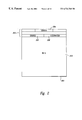
- FIG. 3 shows a generalized block diagram of a network multiplexer.
- FIG. 4 shows an address table for the network of FIG. 1 .
- FIG. 5 displays a network multiplexer interconnecting eight different network media.
- FIG. 6 shows a portion of an address table for the network multiplexer of FIG. 5 .
- FIG. 7 illustrates the logical components of a network multiplexer.
- FIG. 8 illustrates the circular queue data structure used for transmit and receive queues in a network multiplexer.
- FIG. 9 illustrates a currently-available technique for attempting to prevent transmission of stale packets.
- FIG. 10 illustrates a second technique for purging a transmit queue of stale packets.
- FIGS. 11A-F illustrate the method of the present invention.
- FIGS. 12A-C provide a C++-like pseudo-code implementation of the present invention.
- Switches, routers, and bridges are multi-port communications network infrastructure devices that forward communications network packets received from transmitting network devices on or more source network media to receiving network devices on one or more destination network media. Switches, routers, and bridges are all examples of network multiplexers.
- FIG. 1 displays a simple communications network comprising two physically separate network media linked together by a network multiplexer.
- a network medium may be a single ethernet, token ring, or other similar communications network physical transport medium to which a number of network devices, such as computers, printers, disk arrays, and network multiplexers, are attached.
- a computer system 102 and a printer 104 are linked together via a first network medium 106 .
- a second computer system 108 and a third computer system 110 are linked together by a second network medium 112 .
- Both the first and second network media 106 and 112 are linked together by a network multiplexer 114 .
- the first, second, and third computer systems are referred to as “node A,” node B,” and “node C,” respectively.
- the network multiplexer 114 allows node A 102 and the printer 104 , linked together via network medium 106 , to communicate with node B 108 and node C 110 , linked together by network medium 112 .
- the network multiplexer contains two ports, port “X” 116 and port “Y” 118 .
- the network multiplexer 114 receives communications packets, or messages, from node A 102 and the printer 104 through port X 116 and transmits communications packets to node A 102 and the printer 104 through port “X” 116 . In similar fashion, the network multiplexer 114 receives communications packets from, and transmits communications packets to, node B 108 and node C 110 via port “Y” 118 .
- FIG. 2 shows a generalized representation of a communications packet.
- a communications packet 200 is a sequence of computer bytes. Communications packets generally vary in length.
- a header 202 is a first, fixed-length and fixed-format portion of a communications packet. The header contains, among other information, numerical fields that indicate the total length of the communications packet 204 , the address of the network device that originally transmitted the communications packet 206 , and the address of the network device to which the communications packet is directed 208 . Following the header is a variable length field that contains the computer data included in the communications packet 210 . Depending on the type of communications medium, the header may contains many additional fields, including a sequence number and error correction codes, and the fields may occupy many different relative positions to one another and to the start of the header.
- the contents of the source and destination fields 206 and 208 of the header 202 are referred to as the “source address” and “destination address,” respectively, in the following discussion.
- FIG. 3 shows a generalized block diagram of a network multiplexer.
- the network multiplexer 300 is connected, in FIG. 3, to ten different network media 302 - 311 .
- each network medium 302 - 311 is electronically connected to a port 312 - 321 .
- Each port comprises a transceiver device that receives and transmits communications packets and control logic that interprets certain fields of the communications packets in order to implement the lower level networking protocols for the type of network media to which the port is connected, and, additionally, interfaces to an internal communications bus 322 and memory 324 .
- a port may store received communications packets into known locations in the memory 324 and may retrieve communications packets for transmission from known locations in the memory 324 .
- a network multiplexer may also contain a processor 326 and non-volatile memory 328 that stores control routines executed by the processor 326 .
- a network multiplexer may employ complex logic to control forwarding of communications packets from one port to another, or may employ a combination of a processor and specialized logic.
- a network multiplexer When a network multiplexer receives a communications packet from a port, the network multiplexer must determine whether to forward the received communications packet to another port or ports, or to drop the received communications packet. For example, if the network multiplexer 114 of FIG. 1 receives a communications packet from port X 118 with source address corresponding to node A 102 and destination address corresponding to the printer 104 , the network multiplexer 114 may simply drop the received communications packet without forwarding the communications packet to port Y 118 , assuming that network medium 106 is a broadcast-type medium in which the communications controllers of all networking devices connected to the network medium examine each communications packet transferred through the network medium.
- both the printer 104 and the network multiplexer 114 will receive the communications packet transmitted from node A 102 to the printer 104 , and there is no need for the network multiplexer to transmit the communications packet to the printer a second time. In fact, a second, duplicate transmission may cause problems for a receiving node, and for the node that originally transmitted the packet.
- the network multiplexer 114 receives the transmitted communications packet on port X 116 and needs to transmit the communications packet via port Y 118 to network medium 112 in order for node B 108 to receive the communications packet, since because network media 106 and 112 are physically distinct.
- Network 1 is the only bridge, or link, between network medium 106 and network medium 112 .
- the network multiplexer may simply forward received packets. In other cases, the network multiplexer may need to reformat received packets prior to forwarding them.
- the network multiplexer does not contain a hard-wired, destination-address-to-port translation mechanism.
- the network multiplexer 114 receives a communications packet on port X 116 from node A 102 addressed to node B 108 , the network multiplexer has no hard-wired translation mechanism to determine to which of network media 106 and 112 node B is connected.
- ethernet network media for example, 48-bit source and destination addresses are employed.
- Ethernet devices may be removed from one ethernet and connected to another ethernet following their initial connection to an ethernet. There is simply no way to assign an a priori correspondence between ethernet addresses and particular network media, and, even if there were a way to make an a priori assignment, the size of the assignment table would exceed any currently-available technology for economically storing such a volume of information within a network multiplexer.
- FIG. 4 shows an address table for the network of FIG. 1 .
- Each network address in the first column 402 of the address table is paired with a corresponding port in the second column 404 of the address table.
- the network multiplexer When the network multiplexer receives a communications packet with a destination network address that is not currently contained in the address table, the network multiplexer must forward the received communications packet to all the different network media to which the network multiplexer is connected, including the network medium from which the communications packet was received, since the network multiplexer cannot determine to which port the destination address corresponds. After the network multiplexer receives a communications packet from a network device having the particular network address, a correspondence between the particular network address and the port through which the communications packet was received is entered by the network multiplexer into the address table.
- the network multiplexer can find the correspondence between the particular network address and a port in the address table, and can forward the communications packet to the correct port. In the case that the communications packet is received from the same port through which the communications packet would otherwise be forwarded, the network multiplexer can simply drop the packet without forwarding it.
- Network multiplexers may be connected to a large number of different network media through a large number of corresponding ports.
- FIG. 5 displays a network multiplexer interconnecting eight networks
- FIG. 6 shows a portion of an address table for this network multiplexer.
- the address table 602 in FIG. 6 may contain many different network addresses corresponding to a particular port, such as network addresses 604 - 607 associated with the network medium connected to the network multiplexer via port 8 .
- FIG. 7 illustrates the logical components of a network multiplexer.
- the network multiplexer 700 of FIG. 7 includes six ports 702 - 707 . Each port is associated with a transmit queue and a receive queue, such as the transmit queue 708 and the receive queue 710 associated with port 702 . Both transmit and receive queues are composed of contiguous memory locations within the memory of the network multiplexer ( 324 in FIG. 3 ).
- the memory of the network multiplexer ( 324 in FIG. 3) is shown in FIG. 7 as also containing an address table 712 and various stored communications packets, such as stored communications packet 714 .
- the transmit and receive queues contain message descriptors that indicate the memory locations of stored communications packets, such as stored communications packet 714 , and may contain additional information fields.
- the communications controller components of the ports receive communications packets for transmission via message descriptors contained in transmit queues, and place communications packets received from the corresponding network medium into memory locations described by message descriptors contained in receive queues.
- a principle task of the network multiplexer is to move message descriptors from receive queues to transmit queues using information contained in the source and destination fields of the communications packet headers referenced by the message descriptors along with information stored in address table 712 . For example, in FIG.
- the multi-headed arrow 716 illustrates the transfer of message descriptors from the receive queue 710 of port 702 to the transmit queues of the remaining ports 703 - 707
- the multi-headed arrow 718 indicates the transfer of message descriptors from the receive queues of ports 703 - 707 to the transmit queue 708 of port 702 .
- Equivalent systems of arrows can be drawn with respect to each of the remaining ports 703 - 707 .
- the port 702 When the port 702 receives a communications packet from its corresponding network medium, the port obtains a memory location allocated for storage of an incoming communications packet, places the communications packet into memory starting at the obtained memory location, and stores a reference to the memory location, possibly along with additional information, into a message descriptor in the receive queue 710 . Then, the network multiplexer moves the message descriptor that describes the location of the received communications packet from the receive queue 710 of port 702 to a transmit queue of one of the ports 702 - 707 .
- ports 702 - 707 receives a communications packet addressed to a network device linked to the network medium associated with port 702 , that port obtains a memory location into which the received communications packet is stored, and stores a reference to the memory location, possibly along with additional information, into a message descriptor in the receive queue associated with the port.
- the network multiplexer then transfers the message descriptor from the receive queue of the port that received the communications packet to the transmit queue 708 of port 702 to allow port 702 to forward the received communications packet to the network medium associated with port 702 .
- the network multiplexer must place copies of the message descriptor into each transmit queue of each port, a process called “flooding.”
- the network multiplexer is responsible for maintaining message descriptors in the receive queues of all ports that refer to free locations in memory into which received communications packets can be stored.
- FIG. 8 illustrates the circular queue data structure used for transmit and receive queues in a network multiplexer.
- a circular queue is a first-in-first-out (“FIFO”) queue that is logically represented in a circular fashion, such as the depiction of the circular queue 802 at the top of FIG. 8 .
- Each radial section 804 - 812 , or slot, of a circular queue contains space for a queue entry, in the case of network multiplexers, a message descriptor.
- the circular queue 802 in FIG. 8 is shown with 8 queue entry slots 804 - 812 although, in practice, a circular queue may have many tens or hundreds of queue entries.
- a circular queue is associated with two pointers: (1) a consumer index that points to the next queue entry that can be removed from the circular queue by a consumer of queue entries; and (2) a producer index that points to the next open slot within the circular queue in which a producer can place a queue entry to be added to the queue.
- the consumer index may be called the “tail” and the producer index may be called the “head.”
- both the consumer index 814 and the producer index 816 point to the same empty queue entry slot 812 .
- a circular queue with one valid queue entry 818 is produced.
- the consumer index 820 is not changed, as a result of which the consumer index points to the single valid queue entry 822 in the circular queue 818 .
- the producer increments the producer index 824 to point to the next available slot 826 within the circular queue 818 into which the producer can add a second queue entry. If the consumer now removes the single queue entry 822 , an empty circular queue 828 is produced. When the consumer has removed the available queue entry 822 , the consumer increments the consumer index 830 .
- the empty circular queue 828 produced by removing the single queue entry 822 has both the consumer index 830 and the producer index 832 pointing to the same empty, available queue entry slot 834 . If a producer successively adds queue entries at a faster rate than a consumer can consume them, a full circular queue 836 will eventually be produced. In a full circular queue 836 , the producer index 838 points to a single empty queue entry slot within the circular queue that immediately precedes the first available valid queue entry 842 pointed to by the consumer index 844 .
- a transmitting device expects to receive an acknowledgement packet from a receiving device within some maximum period of time. If an acknowledgement is not received by the transmitting device within the period of time, the transmitting device will attempt to retransmit the unacknowledged communications packet to the receiving device. Complexities in network controller control functionality may arise in the case that the transmitting device retransmits a communications packet that is delayed for a time greater than the maximum period of time for acknowledgement, but that is received by the receiving device and subsequently acknowledged by the receiving device. Thus, in order to forestall the repercussions resulting from the acknowledgement of packets assumed to have been lost by transmitting nodes, the maximum transmit delay is specified by the network medium hardware specification and protocol specification. If a transmitted packet is not received by a receiving network device within a maximum transit delay time, the transmitting device can assume that the packet was lost or garbled in transmission.
- Network multiplexers introduce a potential delay in the transmission time for communications packets.
- the transceiver associated with a port may be unable, for a period of time, to transmit packets for which message descriptors have been placed in its associated transmit queue.
- the transmit queue may accumulate a relatively large number of queued message descriptors, and even if the transceiver resumes uninterrupted operation, the most recently queued packets in the transmit queue may not be transmitted by the transceiver in a sufficiently timely fashion to allow the packets to reach their intended destination devices within the maximum time for acknowledgement.
- the network multiplexer needs a method for detecting stale packets queued to transmit queues from those transit queues to prevent their transmission by the transceiver of an associated port following expiration of the maximum delay time for the stale packets.
- the IEEE802.1D ethernet standard specifies that packets should be discarded when their transmit delay time has exceeded one second and that in no case should the transit time for a packet exceed four seconds.
- FIG. 9 illustrates a currently-available technique for attempting to prevent transmission of stale packets.
- message descriptors e.g. message descriptor 902
- in the transmit queue 904 associated with a network multiplexer port 906 are successively removed from the transmit queue by the port (indicated in FIG. 9 by arrow 908 ) and either discarded 910 or, in the most common case, used by the port to retrieve the contents of a data packet from memory in order that the retrieved communications packet can be transmitted 912 to the communications network medium associated with the port.
- the port includes a local timer 914 that is reset upon transmission of each communications packet and is incremented at frequent clock intervals prior to transmission of the next communications packet.
- the communications packet is assumed by the port to have not been successfully transmitted and is discarded 910 .
- the local timer expires after between 10 and 200 milliseconds.
- a recently queued entry such as entry 916 , may fail to reach the port 906 prior to its maximum transit delay time because of transmit failures of packets described by message descriptors queued ahead of the recently queued descriptor 916 .
- the port succeeds in transmitting entry 916 after a failed transmission of 20 previous packets with local timer expiration after 200 milliseconds, then even if the communications packet referenced by entry 916 is successfully transmitted prior to the 200 millisecond timer expiration, the entry 916 will have resided in the transmit queue for more than the specified four-second maximum transit delay time.
- Another problem with the technique illustrated in FIG. 9 is that the transceiver, during the back off process due to collisions, may be unable to transmit a packet within the local timer expiration period, although, in principle, the packet could still be transmitted successfully providing that the maximum transit delay time has not been exceeded.
- the port may end up unnecessarily discarding packets due to the transceiver back off protocol.
- the technique illustrated in FIG. 9 is both unreliable and potentially inefficient.
- FIG. 10 illustrates a second technique for purging a transmit queue of stale packets.
- Each entry in the transmit queue 1002 of FIG. 10 includes a time stamp, such as time stamp 1004 associated with message descriptor 1006 in entry 1008 .
- a time stamp is assigned to each message descriptor upon reception of the corresponding communications packet by the network multiplexer.
- large, monotonically increasing integers are used as time stamps.
- the port 1010 associated with the transmit queue 1002 includes a current threshold time stamp value 1012 that monotonically increases under the control of a system-wide clock.
- the port compares the time stamp 1016 associated with the dequeued message descriptor 1014 to the current threshold time stamp value 1012 , and, if the time stamp 1016 is smaller than the threshold value 1012 , the port discards the message descriptor 1018 , because the communications packet corresponding to the message descriptor has grown stale. Otherwise, the communications packet corresponding to the message descriptor was received sufficiently recently by the network multiplexer that it can be transmitted by the port to its intended destination prior to expiration of the maximum transmit delay time for that packet.
- the time stamp method illustrated in FIG. 10 is reliable, but may result in significantly increased memory requirements for implementing transmit queues.
- the time stamp must be a fairly large integer, to avoid frequent wrapping of the time stamp threshold and corresponding failure of the comparison algorithm used by the port to determine whether a time stamp indicates that an associated; message descriptor has become stale.
- each port having a transmit queue with many tens or hundreds of entries a comparatively large amount of memory will be used for storing time stamps. Because memory size is a fundamental constraint in the design and manufacture of network multiplexers, particularly for network multiplexers having control functionality implemented entirely within integrated circuits, the time stamp method illustrated in FIG. 10 is often too expensive in memory usage for incorporation into network multiplexers.
- FIGS. 11A-F illustrate the method of the present invention.
- two transmit queues 1102 and 1104 are shown along with a graphical representation of a system-wide timer 1106 .
- the present invention will be illustrated with respect to an ethernet network multiplexer.
- the system-wide clock is incremented in one-second intervals 1108 - 1111 .
- a transmit queue monitoring function is awakened.
- the actions of the transmit queue monitoring function will be illustrated in the series of figures starting with FIG. 11 A and ending with FIG. 11 F.
- the current state of the system-wide clock is indicated by the single clock hand 1112 within the graphical representation of the system-wide clock 1106 .
- the clock in a network multiplexer is implemented in hardware, and produces electronic signals rather than moving a clock hand.
- the same numerical labels used in FIG. 11A will be used throughout FIGS. 11A-F.
- the transmit queue 1102 contains three message descriptors 1112 - 1114 .
- the next message descriptor to be removed will be message descriptor 1112 and the most recently queued message descriptor is message descriptor 1114 .
- Transmit queue 1104 contains a single message descriptor 1116 .
- Each queue entry contains a bit flag paired with the message descriptor, such as the bit flag 1118 paired with the message descriptor 1112 .
- the bit flag is set to zero.
- FIGS. 11A-F begins just prior to invocation of the transmit queue monitoring function that will occur when the system clock reaches the zero second marker 1108 .
- This initial time point will be called “ ⁇ ” and is shown in FIGS. 11A-F by the radial line segment 1120 .
- the most recently queued message descriptor in transmit queue 1102 is also labeled “ ⁇ ” to indicate that it was queued at time “ ⁇ .”
- FIG. 11B shows the state of the two transmit queues after the system clock has advanced past the zero second point 1108 , a time referred to in FIGS. 11B-F as “ ⁇ ,” indicated in FIGS. 11B-F by the radial line segment 1122 .
- ⁇ time referred to in FIGS. 11B-F as “ ⁇ ,” indicated in FIGS. 11B-F by the radial line segment 1122 .
- the lapse of time between times “ ⁇ ” and “ ⁇ ” and the present time are indicated by semi-circular, directed line segments, such as semi-circular directed line segment 1124 .
- the transmit queue monitoring function was invoked. The transmit queue monitoring function examines each entry in each transmit queue.
- the transmit queue monitoring function changes the bit flag from “0” to “1” for all transmit queue entries having a bit flag value of “0”, and discards all transmit queue entries having a bit flag value of “1.”
- a new entry 1126 has been queued into transmit queue 1102 at time “ ⁇ ,” and is marked with a symbol “ ⁇ ” in FIGS. 11B-F. Note that the transmit queue entries that had already been queued into the transmit queues at time “ ⁇ ,” and that were shown in FIG. 11A, now have bit flag values of “1,” while the newly queued entry 1126 has a bit flag value of “0.”
- the system clock has advanced to a time just prior to the one second marker 1128 .
- the transmit queue entries 1112 and 1113 of transmit queue 1102 in FIG. 11A have been processed by the port associated with transmit queue 1102 and de-queued from transmit queue 1102 .
- the single entry 1116 in transmit queue 1104 in FIG. 11A has also been processed by the port associated with transmit queue 1104 and has been de-queued from transmit queue 1104 .
- Transmit queue 1102 has started to back up, because the transceiver component of the port associated with transmit queue 1102 has detected a packet collision and has transitioned into a back off mode in which no further communications packets are transferred for a specified length of time.
- four additional entries 1130 - 1133 have been queued to transmit queue 1102 .
- FIG. 11D the system clock has advanced past the one second mark 1128 and the transmit queue monitoring function has been invoked a second time.
- queue entry 1114 of transmit queue 1102 which had a bit flag value of “1,” was removed from transmit queue 1102 and discarded by the transmit queue monitoring function.
- the bit flags of the remaining queue entries of FIG. 11D were changed by the transmit queue monitoring function from “0” to “1.”
- another queue entry 1134 has been queued to transmit queue 1104 .
- the time point at which the queue entry 1114 was dequeued and discarded form transmit queue 1102 by the transmit queue monitoring function is marked with radial line segment 1136 .
- queue entry 1114 was discarded after residing in the queue for slightly more than one second, indicated in FIG. 11D by the semi-circular line segment 1140 .
- the system clock has advanced to a time point just prior to the two-second marker 1142 . Additional entries have been queued to transmit queue 1104 and six additional entries have been queued to transmit queue 1102 . Transmit queue 1102 is still backed up.
- the system clock has advanced to a point just past the two-second mark 1142 and the transmit queue monitoring function has been called a third time.
- the queue entries that had bit flag values of “1” in FIG. 11E have been dequeued from transmit queue 1102 by the transmit queue monitoring function and discarded, including the entry 1126 that was originally queued to the transmit queue at time “ ⁇ ” illustrated in FIG. 11 B.
- queue entry 1126 resided in transmit queue 1102 for just under two seconds, indicated in FIG. 11F by semi-circular line segment 1144 .
- a queue entry may reside in a transmit queue for anywhere from slightly more than one second, as, for example, queue entry 1114 , to slightly less than two seconds, as, for example, queue entry 1126 .
- the method of the present invention guarantees that no queue entry will reside in a transmit queue for longer than two seconds before being discarded by the transmit queue monitoring function.
- stale queue entries are discarded well before the maximum transit delay time of four seconds for the ethernet.
- FIGS. 12A-C a C++-like pseudo-code implementation of the method of the present invention is provided.
- a number of classes are declared to set the stage for implementation of a number of transmit queue routines that illustrate the method of the present invention.
- Implementations for the member functions of many of these initial classes are not shown for the sake of brevity. These member functions involve well-known software techniques that can be easily implemented by an ordinarily-skilled software practitioner. Moreover, many alternative implementations can be developed to effect the functionality described by these classes.
- FIG. 12 A Three initial, stage-setting classes are declared in FIG. 12 A. These classes include: (1) “message,” declared on lines 3 - 12 of FIG. 12A, an instance of which represents a communications packet; and (2) “messageDescriptor,” declared on lines 14 - 27 of FIG. 12A, an instance of which represents a transmit queue entry.
- a message descriptor includes a data member “msgPtr,” a pointer to a communications packet, or message, declared on line 17 of FIG. 12A, and a Boolean data member “flag,” declared on line 18 of FIG. 12A, which represents a bit flag such as bit flag 1118 in FIG. 11 A.
- the member function “query,” declared on line 24 of FIG. 12A, returns the Boolean value TRUE if the instance of a message descriptor class for which data member function “query” is called has a Boolean value TRUE, or “1,” stored within the message descriptor's Boolean data member “flag.” Otherwise, the member data function “query” sets the Boolean data member “flag” to Boolean value TRUE, or “1,” and returns the Boolean value FALSE.
- An implementation for the member function “query” is shown on lines 34 - 42 . The member function “query” is used during transmit queue monitoring to ascertain which queue entries are stale so that they can be discarded.
- the class “transmitQueue” is declared on lines 1 - 19 of FIG. 12B, and implementations of various transmit queue member functions follow that declaration in FIGS. 12B and 12C.
- Member functions of the class “transmitQueue” include: (1) “empty,” declared on line 7 of FIG. 12B, which returns a Boolean value indicating whether or not the transmit queue is empty; (2) “full,” declared on line 8 of FIG.
- an instance of the transmit queue includes an array of message descriptors, called “queue,” declared on line 4 , and integer indexes that represent the head and tail pointers of the transmit queue, declared on lines 5 and 6 of FIG. 12 D.
- the implementations of the private member functions “empty,” “full,” “num.” “inc,” and “dec” are relatively straight forward and will not be described further, as is also the case with the public transmit queue member functions “queueMDesc” and “dequeueMDesc.”
- the method of the present invention is embodied in the Boolean data member “flag” of the class “messageDescriptor” and in the transmit queue member function “tick,” an implementation for which is given on lines 81 - 91 of FIG. 12 C.
- the transmit queue member function “tick” is called by the network multiplexer for each transmit queue at one second intervals, controlled by a system-wide clock. If the transmit queue is empty, as detected by member function “tick” on line 85 , tick simply returns. Otherwise, tick sets the local variable “i” to point to the least recently queued entry in the transmit queue.
- tick continuously decrements the pointer “i” while the message descriptor entry referenced by the pointer “i” within the transmit queue returns the Boolean value FALSE in response to invocation of the message descriptor member function “query.” If the member function “dec” returns the Boolean value FALSE, indicating that no further queue entries remain in the transmit queue, then tick returns, because the bit flags for all queue entries have been changed from “0” to “1” by repeated calls to the message descriptor member function “query” and because no queue entry was found with a bit flag value of “1.” However, if tick does not return on line 88 , then there are queue entries with bit flag values of “1” remaining in the transmit queue.
- Tick discards these queue entries by setting the data member “tail” to the last non-stale queue entry detected during execution of the while-loop of line 88 and line 90 .
- all stale queue entries have been removed and all queue entries that previously had bit flag values of zero now have bit flag values of one.
- the transmit queue monitoring function illustrated in FIGS. 11A-F and implemented in FIGS. 12A-C can be implemented in any number of different computer languages, an almost limitless number of ways, or, alternatively, can be implemented as logic circuits within an integrated circuit implementation of the control functionality of a network multiplexer.
- the removal of queue entries that have grown stale after specified periods of time is a generally useful method in many types of electronic devices and in many types of computer software programs.
- the method and system of the present invention may be profitably applied in a vast number of applications outside of network multiplexers.
- the timing of transmit queue monitoring function invocations can vary, depending on protocol-specified maximum transit delays.
Abstract
Description
Claims (13)
Priority Applications (1)
| Application Number | Priority Date | Filing Date | Title |
|---|---|---|---|
| US09/449,840 US6724768B1 (en) | 1999-11-26 | 1999-11-26 | Method and system for enforcing maximum transit delay in network multiplexers |
Applications Claiming Priority (1)
| Application Number | Priority Date | Filing Date | Title |
|---|---|---|---|
| US09/449,840 US6724768B1 (en) | 1999-11-26 | 1999-11-26 | Method and system for enforcing maximum transit delay in network multiplexers |
Publications (1)
| Publication Number | Publication Date |
|---|---|
| US6724768B1 true US6724768B1 (en) | 2004-04-20 |
Family
ID=32070019
Family Applications (1)
| Application Number | Title | Priority Date | Filing Date |
|---|---|---|---|
| US09/449,840 Expired - Fee Related US6724768B1 (en) | 1999-11-26 | 1999-11-26 | Method and system for enforcing maximum transit delay in network multiplexers |
Country Status (1)
| Country | Link |
|---|---|
| US (1) | US6724768B1 (en) |
Cited By (6)
| Publication number | Priority date | Publication date | Assignee | Title |
|---|---|---|---|---|
| US20030072310A1 (en) * | 2001-10-09 | 2003-04-17 | Jean-Marc Reme | System for transmitting sequences of packets between a server and a mobile terminal |
| US20040240459A1 (en) * | 2003-05-31 | 2004-12-02 | Lo John M. | Method and apparatus for avoiding collisions during packet enqueue and dequeue |
| US20060104216A1 (en) * | 2004-11-17 | 2006-05-18 | 3Com Corporation | Packet metering in high-speed network units |
| US7187689B1 (en) * | 2001-10-29 | 2007-03-06 | Juniper Networks, Inc. | Self-cleaning mechanism for error recovery |
| US20100174608A1 (en) * | 2007-03-22 | 2010-07-08 | Harkness David H | Digital rights management and audience measurement systems and methods |
| US10613998B2 (en) * | 2018-07-30 | 2020-04-07 | EMC IP Holding Company LLC | Multi-level time decay storage queue |
Citations (9)
| Publication number | Priority date | Publication date | Assignee | Title |
|---|---|---|---|---|
| US5751951A (en) * | 1995-10-30 | 1998-05-12 | Mitsubishi Electric Information Technology Center America, Inc. | Network interface |
| US5951706A (en) * | 1997-06-30 | 1999-09-14 | International Business Machines Corporation | Method of independent simultaneous queueing of message descriptors |
| US5996019A (en) * | 1995-07-19 | 1999-11-30 | Fujitsu Network Communications, Inc. | Network link access scheduling using a plurality of prioritized lists containing queue identifiers |
| US6031842A (en) * | 1996-09-11 | 2000-02-29 | Mcdata Corporation | Low latency shared memory switch architecture |
| US6144640A (en) * | 1996-08-30 | 2000-11-07 | Sgs-Thomson Microelectronics Limited | ATM switch |
| US6256315B1 (en) * | 1998-10-27 | 2001-07-03 | Fujitsu Network Communications, Inc. | Network to network priority frame dequeuing |
| US6292490B1 (en) * | 1998-01-14 | 2001-09-18 | Skystream Corporation | Receipts and dispatch timing of transport packets in a video program bearing stream remultiplexer |
| US6405258B1 (en) * | 1999-05-05 | 2002-06-11 | Advanced Micro Devices Inc. | Method and apparatus for controlling the flow of data frames through a network switch on a port-by-port basis |
| US6556579B1 (en) * | 1999-09-21 | 2003-04-29 | 3Com Corporation | Method and apparatus for detecting duplicate buffers in a descriptor based multi-port queue |
-
1999
- 1999-11-26 US US09/449,840 patent/US6724768B1/en not_active Expired - Fee Related
Patent Citations (9)
| Publication number | Priority date | Publication date | Assignee | Title |
|---|---|---|---|---|
| US5996019A (en) * | 1995-07-19 | 1999-11-30 | Fujitsu Network Communications, Inc. | Network link access scheduling using a plurality of prioritized lists containing queue identifiers |
| US5751951A (en) * | 1995-10-30 | 1998-05-12 | Mitsubishi Electric Information Technology Center America, Inc. | Network interface |
| US6144640A (en) * | 1996-08-30 | 2000-11-07 | Sgs-Thomson Microelectronics Limited | ATM switch |
| US6031842A (en) * | 1996-09-11 | 2000-02-29 | Mcdata Corporation | Low latency shared memory switch architecture |
| US5951706A (en) * | 1997-06-30 | 1999-09-14 | International Business Machines Corporation | Method of independent simultaneous queueing of message descriptors |
| US6292490B1 (en) * | 1998-01-14 | 2001-09-18 | Skystream Corporation | Receipts and dispatch timing of transport packets in a video program bearing stream remultiplexer |
| US6256315B1 (en) * | 1998-10-27 | 2001-07-03 | Fujitsu Network Communications, Inc. | Network to network priority frame dequeuing |
| US6405258B1 (en) * | 1999-05-05 | 2002-06-11 | Advanced Micro Devices Inc. | Method and apparatus for controlling the flow of data frames through a network switch on a port-by-port basis |
| US6556579B1 (en) * | 1999-09-21 | 2003-04-29 | 3Com Corporation | Method and apparatus for detecting duplicate buffers in a descriptor based multi-port queue |
Cited By (12)
| Publication number | Priority date | Publication date | Assignee | Title |
|---|---|---|---|---|
| US20030072310A1 (en) * | 2001-10-09 | 2003-04-17 | Jean-Marc Reme | System for transmitting sequences of packets between a server and a mobile terminal |
| US7187689B1 (en) * | 2001-10-29 | 2007-03-06 | Juniper Networks, Inc. | Self-cleaning mechanism for error recovery |
| US20070118702A1 (en) * | 2001-10-29 | 2007-05-24 | Juniper Networks, Inc. | Self-cleaning mechanism for error recovery |
| US7876769B2 (en) | 2001-10-29 | 2011-01-25 | Juniper Networks, Inc. | Self-cleaning mechanism for error recovery |
| US20110087930A1 (en) * | 2001-10-29 | 2011-04-14 | Juniper Networks, Inc. | Self-cleaning mechanism for error recovery |
| US8462804B2 (en) | 2001-10-29 | 2013-06-11 | Juniper Networks, Inc. | Self-cleaning mechanism for error recovery |
| US20040240459A1 (en) * | 2003-05-31 | 2004-12-02 | Lo John M. | Method and apparatus for avoiding collisions during packet enqueue and dequeue |
| US7404058B2 (en) * | 2003-05-31 | 2008-07-22 | Sun Microsystems, Inc. | Method and apparatus for avoiding collisions during packet enqueue and dequeue |
| US20060104216A1 (en) * | 2004-11-17 | 2006-05-18 | 3Com Corporation | Packet metering in high-speed network units |
| US7349335B2 (en) * | 2004-11-17 | 2008-03-25 | 3Com Corporation | Packet metering in high-speed network units |
| US20100174608A1 (en) * | 2007-03-22 | 2010-07-08 | Harkness David H | Digital rights management and audience measurement systems and methods |
| US10613998B2 (en) * | 2018-07-30 | 2020-04-07 | EMC IP Holding Company LLC | Multi-level time decay storage queue |
Similar Documents
| Publication | Publication Date | Title |
|---|---|---|
| KR101885935B1 (en) | Method and apparatus for serial data transmission at a switchable data rate | |
| Di Natale et al. | Understanding and using the controller area network communication protocol: theory and practice | |
| US5619651A (en) | I/O data unit symmetry in a media access control/host system interface unit | |
| US6857030B2 (en) | Methods, system and article of manufacture for pre-fetching descriptors | |
| EP0851623B1 (en) | Multiplex transmission system | |
| EP0525985A2 (en) | High speed data link interface | |
| JPH06236328A (en) | Processing method of message containing error in data processor | |
| US20080005296A1 (en) | Method and apparatus for synchronizing use of buffer descriptor entries | |
| JPH11504496A (en) | Low latency, high clock frequency, pregio asynchronous packet-based crossbar switching chip system and method | |
| US7876769B2 (en) | Self-cleaning mechanism for error recovery | |
| KR100464195B1 (en) | Method and apparatus for providing a reliable protocol for transferring data | |
| US6735620B1 (en) | Efficient protocol for retransmit logic in reliable zero copy message transport | |
| US6594270B1 (en) | Ageing of data packets using queue pointers | |
| US20040156368A1 (en) | Frame alteration logic for network processors | |
| WO2002084498A1 (en) | Reduced-overhead dma | |
| WO2001015364A1 (en) | Deferrable processing option for fast path forwarding | |
| US6724768B1 (en) | Method and system for enforcing maximum transit delay in network multiplexers | |
| EP1351439B1 (en) | Embedded system for broadcast traffic congestion control in communication network | |
| US6697330B1 (en) | Method and system for output flow control in network multiplexers | |
| JP2986798B2 (en) | Data transmission control method and data communication device | |
| JP4807828B2 (en) | Envelope packet architecture for broadband engines | |
| US5948079A (en) | System for non-sequential transfer of data packet portions with respective portion descriptions from a computer network peripheral device to host memory | |
| EP1052873A2 (en) | A memory management technique for maintaining packet order in a packet processing system | |
| KR19980079676A (en) | Source and Destination Initiated Interrupt System for Message Arrival Notification | |
| EP1508225A2 (en) | Method for data storage in external and on-chip memory in a packet switch |
Legal Events
| Date | Code | Title | Description |
|---|---|---|---|
| AS | Assignment |
Owner name: HEWLETT-PACKARD COMPANY, COLORADO Free format text: ASSIGNMENT OF ASSIGNORS INTEREST;ASSIGNOR:MELVIN, BRUCE W.;REEL/FRAME:010674/0747 Effective date: 20000218 |
|
| AS | Assignment |
Owner name: HEWLETT-PACKARD DEVELOPMENT COMPANY L.P., TEXAS Free format text: ASSIGNMENT OF ASSIGNORS INTEREST;ASSIGNOR:HEWLETT-PACKARD COMPANY;REEL/FRAME:014061/0492 Effective date: 20030926 Owner name: HEWLETT-PACKARD DEVELOPMENT COMPANY L.P.,TEXAS Free format text: ASSIGNMENT OF ASSIGNORS INTEREST;ASSIGNOR:HEWLETT-PACKARD COMPANY;REEL/FRAME:014061/0492 Effective date: 20030926 |
|
| FPAY | Fee payment |
Year of fee payment: 4 |
|
| REMI | Maintenance fee reminder mailed | ||
| FEPP | Fee payment procedure |
Free format text: PAYOR NUMBER ASSIGNED (ORIGINAL EVENT CODE: ASPN); ENTITY STATUS OF PATENT OWNER: LARGE ENTITY |
|
| FPAY | Fee payment |
Year of fee payment: 8 |
|
| AS | Assignment |
Owner name: HEWLETT PACKARD ENTERPRISE DEVELOPMENT LP, TEXAS Free format text: ASSIGNMENT OF ASSIGNORS INTEREST;ASSIGNOR:HEWLETT-PACKARD DEVELOPMENT COMPANY, L.P.;REEL/FRAME:037079/0001 Effective date: 20151027 |
|
| REMI | Maintenance fee reminder mailed | ||
| LAPS | Lapse for failure to pay maintenance fees | ||
| STCH | Information on status: patent discontinuation |
Free format text: PATENT EXPIRED DUE TO NONPAYMENT OF MAINTENANCE FEES UNDER 37 CFR 1.362 |
|
| FP | Lapsed due to failure to pay maintenance fee |
Effective date: 20160420 |