US6726285B2 - Cellular chair construction - Google Patents
Cellular chair construction Download PDFInfo
- Publication number
- US6726285B2 US6726285B2 US09/897,153 US89715301A US6726285B2 US 6726285 B2 US6726285 B2 US 6726285B2 US 89715301 A US89715301 A US 89715301A US 6726285 B2 US6726285 B2 US 6726285B2
- Authority
- US
- United States
- Prior art keywords
- structures
- seating structure
- web
- seating
- boss
- Prior art date
- Legal status (The legal status is an assumption and is not a legal conclusion. Google has not performed a legal analysis and makes no representation as to the accuracy of the status listed.)
- Expired - Lifetime
Links
Images


Classifications
-
- A—HUMAN NECESSITIES
- A47—FURNITURE; DOMESTIC ARTICLES OR APPLIANCES; COFFEE MILLS; SPICE MILLS; SUCTION CLEANERS IN GENERAL
- A47C—CHAIRS; SOFAS; BEDS
- A47C5/00—Chairs of special materials
- A47C5/12—Chairs of special materials of plastics, with or without reinforcement
-
- A—HUMAN NECESSITIES
- A47—FURNITURE; DOMESTIC ARTICLES OR APPLIANCES; COFFEE MILLS; SPICE MILLS; SUCTION CLEANERS IN GENERAL
- A47C—CHAIRS; SOFAS; BEDS
- A47C3/00—Chairs characterised by structural features; Chairs or stools with rotatable or vertically-adjustable seats
- A47C3/12—Chairs characterised by structural features; Chairs or stools with rotatable or vertically-adjustable seats with shell-shape seat and back-rest unit, e.g. having arm rests
-
- A—HUMAN NECESSITIES
- A47—FURNITURE; DOMESTIC ARTICLES OR APPLIANCES; COFFEE MILLS; SPICE MILLS; SUCTION CLEANERS IN GENERAL
- A47C—CHAIRS; SOFAS; BEDS
- A47C7/00—Parts, details, or accessories of chairs or stools
- A47C7/02—Seat parts
-
- A—HUMAN NECESSITIES
- A47—FURNITURE; DOMESTIC ARTICLES OR APPLIANCES; COFFEE MILLS; SPICE MILLS; SUCTION CLEANERS IN GENERAL
- A47C—CHAIRS; SOFAS; BEDS
- A47C7/00—Parts, details, or accessories of chairs or stools
- A47C7/02—Seat parts
- A47C7/16—Seats made of wooden, plastics, or metal sheet material; Panel seats
-
- A—HUMAN NECESSITIES
- A47—FURNITURE; DOMESTIC ARTICLES OR APPLIANCES; COFFEE MILLS; SPICE MILLS; SUCTION CLEANERS IN GENERAL
- A47C—CHAIRS; SOFAS; BEDS
- A47C7/00—Parts, details, or accessories of chairs or stools
- A47C7/02—Seat parts
- A47C7/28—Seat parts with tensioned springs, e.g. of flat type
- A47C7/285—Seat parts with tensioned springs, e.g. of flat type with metal strips or webs
-
- A—HUMAN NECESSITIES
- A47—FURNITURE; DOMESTIC ARTICLES OR APPLIANCES; COFFEE MILLS; SPICE MILLS; SUCTION CLEANERS IN GENERAL
- A47C—CHAIRS; SOFAS; BEDS
- A47C7/00—Parts, details, or accessories of chairs or stools
- A47C7/36—Support for the head or the back
- A47C7/40—Support for the head or the back for the back
- A47C7/46—Support for the head or the back for the back with special, e.g. adjustable, lumbar region support profile; "Ackerblom" profile chairs
Definitions
- the present invention relates to chairs and seating normally associated with but not limited to residential or commercial office work. These chairs employ a number of methods of to enhance the user's comfort and promote ergonomically healthy sitting. These methods include various forms of padding and flexing of the seat and back as well as separate mechanical controls that control the overall movement of the seat and back.
- foam padding In the case of simply using foam padding, under normal manufacturing conditions it is difficult if not impossible to properly vary the amount of firmness and thus support from one area of a cushion to another. Additionally, having to use foam can lead to excessive heat-build-up between the seating surface and the occupant.
- One of the problems with foam is the forming/molding of it. Current manufacturing technology makes it a relatively inefficient process compared with the manufacture of the other components that make up a chair of seating surface. The forming/molding of a contoured seating surface is so slow that the manufacturer is forced to make many sets of molds (which usually are hand filled) in order to maintain the production pace.
- the amount of change can vary from fabric to fabric which results in an unpredictability of the firmness of a cushion from one manufactured unit to the next. If a slipcover is used, it must be sized properly. Such sizing can be difficult as a result of the differing mechanical properties found from one fabric to another.
- the most important properties of a fabric when upholstering a contoured surface are its thickness and its rate of stretch. Thickness variations can make one fabric upholster smooth around radii or contours, while a thicker one will wrinkle in the same area. Variations in the amount of stretch can lead to other problems. And so a proper size slipcover in one type of fabric, with its stretch characteristics, can be the wrong size in another type or style of fabric.
- the present invention relates to an improved method of constructing seating surfaces, which provides greater comfort through superior surface adjustment for a variety of users.
- the seating surface construction is comprised of a plurality of support sections, or bosses/platforms and of a plurality of web connectors interconnecting the support sections.
- the support sections, or bosses/platforms are more rigid than their corresponding web connectors.
- a variety of methods are disclosed for making the bosses/platforms exhibit a greater degree of rigidity than the web connectors.
- One such method disclosed is to alter the thickness of the bosses/platforms versus the web connectors.
- another method is to provide the bosses/platforms with stiffening geometry that provides a greater degree of rigidity than the web connectors.
- Such stiffening means could be the addition of one or more returns or ribs.
- the invention also provides greater airflow to contact areas of the occupant's body, because foam is not necessary to create a comfortable seating surface. Additionally, the seating surface is more efficient and economical to produce.
- an object of the present invention is to provide a new and improved method of chair seat and back pan construction, which provides greater comfort for the user.
- a further object of the invention is to provide a new and improved method of chair seat back pan construction, which provides superior surface adjustment for a variety of users.
- a further object of the invention is to provide a new and improved method of chair seat back pan construction, which provides greater airflow to contact areas of the occupant's body.
- a further object of the invention is to provide a new and improved method of chair seat back pan construction, which is more efficient and economical to produce.
- FIG. 1 is top view of the chair showing its support frame with its seat-pan seating surface removed.
- FIG. 2 is a side elevation of the chair according to the present invention.
- FIG. 3 is a front view of the back resilient seating surface.
- FIG. 4 is a front view of the resilient seat-pan seating surface.
- FIG. 5 is a top view of the back seating surface and seat-pan seating surface of figures three and four.
- FIG. 6 is a side view of the back seating surface of figure three.
- FIG. 7 is a top view of the seat-pan frame and the backrest frame that is capable of receiving the seating surfaces of figures three through six.
- FIG. 8 is a front view of the seat-pan frame and the backrest frame that is capable of receiving the seating surfaces of figures three through six.
- FIG. 9 is a side view of the seat-pan frame and the backrest frame, which is capable of receiving the seating surfaces of, figures three through six.
- FIG. 10 is a top view of the seat-pan frame and the backrest frame with the resilient seating surfaces of figures three through six affixed in place.
- FIG. 11 is a front view of the seat-pan frame and the backrest frame with the resilient seating surfaces of figures three through six affixed in place.
- FIG. 12 is a side view of the seat-pan frame and the backrest frame with the resilient seating surfaces of figures three through six affixed in place.
- FIG. 13 is a detail view consisting of a substantially Hat web.
- FIG. 14 is a detail view consisting of a configured web that has a V-shaped cross-section.
- FIG. 15 is a plan view of the webbing structure.
- FIG. 16 is a detail anoxemetric view of FIG. 15, showing one form the web may assume.
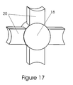
- FIG. 17 is a detail anoxemetric view much like FIG. 16, except a single structural relationship is depicted, showing another form the web may assume.
- FIG. 18 is a detail anoxemetnc view much like FIG. 16, showing several cells linked together.
- FIG. 19 is a detail anoxemetric view much like FIG. 18, except a larger field of structural relationships is depicted.
- FIG. 20 is a side sectional view taken along cutting line A—A of FIG. 19 .
- FIG. 21 is a side sectional view taken along cutting line B—B of FIG. 19 .
- a top view of the seat-pan seating surface and its support frame can be seen.
- the shells or pans can be seen separate from the frames, and the frames can be seen separate from the seating surface shells or pans in FIGS. 1 , 2 , 7 , 8 , and 9 .
- a separate peripheral support frame is not a necessity of the invention, for the shells could be self-supporting with an integral structure.
- a seat-pan, or back-pan seating surface refers to a structure which may be the primary surface, as in a plastic or wood chair, or a structure which may accept foam and upholstery and thus not be the primary surface as can be commonly found in many articles of furniture. Often these structures are also referred to as seating shells. All of these and any other terms used to describe a similar structure are considered to be equivalents and should be viewed as such.
- the seating surface is comprised of a plurality of webs 18 , thicker sections, or bosses/platforms 20 , and openings 22 . It is through the various geometric combinations of the three of these basic elements that improved seating comfort is achieved. This is why we also refer to the matrix as being “cellular” in nature, for it is a matrix of individual, independently acting cell structures. One embodiment has all three of these structures formed economically from one type of material and process such as plastic and molding. Any of the common molding methods known could be used including, but not limited to, injection, blow, or roto-molding.
- these elements may be selectively made from two or more types of materials to further control the overall engineering attributes of the structure. Additionally, this structure could be realized through other manufacturing techniques such as lamination, stamping, punching etc.
- the webs 18 function as thinner or more flexible interconnecting elements to the thicker or more rigid bosses/platform sections 20 . It is through these webs that flexure occurs, allowing movement of one thicker or more rigid section relative another thicker section. Depending upon the final geometry selected this movement may have several degrees of freedom. For example, if the web is of the form as in detail FIG. 16, where the web is predominantly flat in form, the web may act as a both a torsional flexure (occurring predominantly across the webs width) for the thicker or more rigid bosses/platform sections, as well as a linear flexure along its length.
- the web may stretch in length, allowing another form of displacement. If, however, the web is of the form found in detail FIG. 14, where the web is formed as a V, or an inverted V, the web may exhibit the preceding characteristics as well as act as a living hinge allowing the angle formed by the faces of said V to change. This would result in a different set of degrees of freedom of one boss/platform section relative to another. Both of the aforementioned forms of webs, and other contemplated designs, all may share common types of flexure of varying degrees. It should be noted that the terms “thinner” and “thicker” sections are interchangeable with the terms “sections having greater” or “sections having less” flexibility relative to each other.
- Cross-sectional area or thickness is but one way of varying the relative rigidity of the webs vs. the bosses or platforms. Another way is to provide the bosses or platforms with rigidizing returns, ribs or walls, so that structurally the bosses or platforms are stiffer than the joining webs.
- the materials selected could play an important role in the performance of the geometry. For example, if the material selected is an elastomeric material, such as a urethane, the webs 18 could each stretch or elongate a small amount resulting in or allowing deflection or displacement of the thicker or more rigid bosses/platform sections 20 .
- Another flexible material under consideration is HYTREL® polyester elastomer by Dupont.
- each area responding individually the entire seating surface may emulate a soft cushioning effect to the occupant.
- advanced molding techniques or fabrication it is possible through advanced molding techniques or fabrication, to use more than one type of molded material in a finished product.
- One such technique is to mold a part in one material in one mold and then place the part into another mold that has additional cavity area, and then fill that mold with another type of material. So it may be advantageous, for example, to mold all the webs and connective areas in one material in one mold, and then to transfer the part to another mold to form all the thicker or more rigid bosses/platformn sections and other features in another material.
- holes, or areas lacking material are created which allow airflow and thus reduces the amount of heat build up on the seating surface.
- These holes, or areas with no material, further serve to allow the desired movement of the webs and the thicker sections.
- the holes are octagons, but any shape found suitable could be used.
- FIG. 17 a detail anoxemetric view much like FIG. 16, except a single structural relationship is depicted, showing another form the web structure may assume. The difference of this form of web structure can be appreciated by referring to FIGS. 19, 20 , and 21 .
- FIG. 20 which is a sectional view taken along cutting line A—A of FIG. 19
- FIG. 21 which is a sectional view taken along cutting line B—B of FIG. 19, show that the bosses/platforms have reinforcing returns that make the bosses/platforms more rigid than the connecting web structure.
- the return wall on the bosses/platforms forms a ring. This is not a necessity though, the returns could be as simple as a single rib or as complex or as many returns as are needed.
- a critical aspect of this invention is the ability of the designer/manufacturer to precisely control and alter all aspects of the deflection of the seating surface from area to area simply and controllably.
- a designer/manufacturer specifies a foam density (firmness/softness) for a cushion, the entire cushion is compromised by that unifying density. That is not the case with this invention though.
- Biomapping is datum created through the comparison of body contours of a given population, or the datum created through the comparison of contact forces exerted between a seating surface and the occupant.
- exercises in generating data have been ongoing for several years, the designer is still limited to selecting generic contours, and then hopes that the foam would resolve the final fitting issues.
- This invention makes it possible to effectively use the data generated by biomapping to precisely control the geometry (web-connectors, bosses/platforms, and openings) and thus the engineering properties area by area over the entire seating surface, so that each sector-area is functionally optimized.
- FIG. 3 shows how the seating surface could be divided into zones; one such zone is indicated by area 24 . This could be the zone of greatest flexibility. It should also be appreciated the advantage this offers the designer when he is trying to economically manufacture an item from a material such as plastic, as well as the increased comfort that the user will experience.
- both the seating frame 2 and the back frame 4 can be seen. It is substantially more rigid than the seating surface. It provides a support structure for the seating surface, and as a means to connect the seating surface to the rest of the chair. In one contemplated embodiment the seating surface is carried within the seating frame by way of mounting grooves 10 and 12 . It should be appreciated that the seating surface and the frame could be formed or manufactured as a single unit; however, several advantages may be realized if they are separate. One such advantage is that they may be made of differing materials. In this way, each of the materials selected for their respective part may be optimized functionally. Another advantage is that the way in which the two members, the seating surface and its frame, are attached may be variable.
- An example of an attachment means is a rubber mount that may take the form of a series of intermediate mounting pads, which occur between the seating surface and its frame.
- the rubber or resilient material could take the form of a gasket occurring between the seat surface and frame.
- Another way that such movement could be achieved is to produce a groove integral to the seating surface that would follow the same path as the mounting groove. Such a groove could be pleated like the web found in FIG. 14, and thus would allow a degree of lateral movement.
- Another method would be to have the seating surface snap into place using tabs and slots that had enough free-play relative to each other to yield desirable results.
- Either the seating surface or the frame could have the slots and the other the tab members.
- Yet another method would be to configure the two elements so that one or the other had standing legs formed predominantly perpendicular to the other element. In this way, when the two are assembled, and allowed to shift relative to each other, the legs flex. This, like the rubber or resilient mounts would allow biased relative movement, which would not feel loose.
- These tabs or the functionality of them could be combined with the snap tabs, as a matter of fact; any of the methods could be successfully combined. Additionally, any of these attachment techniques could occur using mounting grooves such as 10 and 12 , or could surface mount directly on the surface of the seat/back frames.
- the seating surfaces can be formulated that satisfy the extremes. What is most important in achieving seating comfort, is the contouring that occurs within whatever sized seating surface is chosen. Unfortunately, this contouring varies greatly from a small individual, to a large one. Additionally, some individuals who seemingly share the same body types prefer differing contours such as stronger/weaker lumbar contours. Although the present invention addresses this need for variable contouring through its innovative flexure structure, further advantages in comfort can be realized if the initial contours of the seating structure are in the proper range for the occupant. Through the present invention's unique method of construction, these goals are all achievable. As previously outlined, the seating surfaces can be attached to the seating frame by a variety of methods.
- the manufacturer can produce one basic chair frame(s) and then into the same set of frames insert many different contoured seating surfaces. Obviously, this has the advantage of eliminating the need of the manufacturer having to tool three independent products instead of one. It also has additional advantages. Because the seating surfaces are so easily attached and detached from their frames, it is conducive to a field-customization scenario. In this way, wholesalers, and retailers could stock frames, and then have a variety of seating surfaces in various contours and colors. This would allow the retailer could customize the product on the spot for the customer. Additionally, the end user is not stuck with a chair that at some point in the future may be the wrong size. The size/color scheme can be updated at any point of the products life by simply obtaining a fresh set of seating surfaces.
Abstract
Description
Claims (18)
Priority Applications (5)
| Application Number | Priority Date | Filing Date | Title |
|---|---|---|---|
| US09/897,153 US6726285B2 (en) | 2000-07-03 | 2001-06-29 | Cellular chair construction |
| US10/809,279 US7455365B2 (en) | 2000-07-03 | 2004-03-25 | Seating structure having flexible support surface |
| US10/819,471 US7059682B2 (en) | 2000-07-03 | 2004-04-07 | Seating structure having flexible seating surface |
| US11/103,371 US7472962B2 (en) | 2000-07-03 | 2005-04-11 | Seating structure having flexible support surface |
| US12/315,706 US7794022B2 (en) | 2000-07-03 | 2008-12-05 | Body support structure having a molded elastomeric member |
Applications Claiming Priority (3)
| Application Number | Priority Date | Filing Date | Title |
|---|---|---|---|
| US21525700P | 2000-07-03 | 2000-07-03 | |
| US09/897,153 US6726285B2 (en) | 2000-07-03 | 2001-06-29 | Cellular chair construction |
| PCT/US2002/000024 WO2003061434A1 (en) | 2002-01-03 | 2002-01-03 | Cellular chair construction |
Related Parent Applications (1)
| Application Number | Title | Priority Date | Filing Date |
|---|---|---|---|
| PCT/US2002/000024 Continuation-In-Part WO2003061434A1 (en) | 2000-07-03 | 2002-01-03 | Cellular chair construction |
Related Child Applications (2)
| Application Number | Title | Priority Date | Filing Date |
|---|---|---|---|
| US10/809,279 Continuation-In-Part US7455365B2 (en) | 2000-07-03 | 2004-03-25 | Seating structure having flexible support surface |
| US10/819,471 Continuation US7059682B2 (en) | 2000-07-03 | 2004-04-07 | Seating structure having flexible seating surface |
Publications (2)
| Publication Number | Publication Date |
|---|---|
| US20020021040A1 US20020021040A1 (en) | 2002-02-21 |
| US6726285B2 true US6726285B2 (en) | 2004-04-27 |
Family
ID=32823141
Family Applications (5)
| Application Number | Title | Priority Date | Filing Date |
|---|---|---|---|
| US09/897,153 Expired - Lifetime US6726285B2 (en) | 2000-07-03 | 2001-06-29 | Cellular chair construction |
| US10/809,279 Expired - Lifetime US7455365B2 (en) | 2000-07-03 | 2004-03-25 | Seating structure having flexible support surface |
| US10/819,471 Expired - Lifetime US7059682B2 (en) | 2000-07-03 | 2004-04-07 | Seating structure having flexible seating surface |
| US11/103,371 Expired - Fee Related US7472962B2 (en) | 2000-07-03 | 2005-04-11 | Seating structure having flexible support surface |
| US12/315,706 Expired - Lifetime US7794022B2 (en) | 2000-07-03 | 2008-12-05 | Body support structure having a molded elastomeric member |
Family Applications After (4)
| Application Number | Title | Priority Date | Filing Date |
|---|---|---|---|
| US10/809,279 Expired - Lifetime US7455365B2 (en) | 2000-07-03 | 2004-03-25 | Seating structure having flexible support surface |
| US10/819,471 Expired - Lifetime US7059682B2 (en) | 2000-07-03 | 2004-04-07 | Seating structure having flexible seating surface |
| US11/103,371 Expired - Fee Related US7472962B2 (en) | 2000-07-03 | 2005-04-11 | Seating structure having flexible support surface |
| US12/315,706 Expired - Lifetime US7794022B2 (en) | 2000-07-03 | 2008-12-05 | Body support structure having a molded elastomeric member |
Country Status (5)
| Country | Link |
|---|---|
| US (5) | US6726285B2 (en) |
| CA (2) | CA2472222C (en) |
| GB (1) | GB2399008B (en) |
| MX (1) | MXPA04006586A (en) |
| WO (1) | WO2003061434A1 (en) |
Cited By (58)
| Publication number | Priority date | Publication date | Assignee | Title |
|---|---|---|---|---|
| US20050001464A1 (en) * | 2000-07-03 | 2005-01-06 | Herman Miller, Inc. | Seating structure having flexible seating surface |
| US20050116526A1 (en) * | 2003-10-23 | 2005-06-02 | Herman Miller, Inc. | Pixelated support structures and elements |
| US20050279591A1 (en) * | 2004-06-17 | 2005-12-22 | Coffield Timothy P | Load bearing surface |
| US20060103198A1 (en) * | 2004-08-05 | 2006-05-18 | Thomas Dettmann | Music posture chairs |
| US20070262634A1 (en) * | 2006-05-12 | 2007-11-15 | Brill Ryan S | Suspended pixelated seating structure |
| US20080030062A1 (en) * | 2006-07-19 | 2008-02-07 | Prust Peter C | Seat Cushion |
| US20080290712A1 (en) * | 2006-10-04 | 2008-11-27 | Formway Furniture Limited | Chair |
| US20090127905A1 (en) * | 2002-02-13 | 2009-05-21 | Herman Miller, Inc. | Back support structure |
| US7574572B2 (en) | 2004-05-31 | 2009-08-11 | Panasonic Corporation | Cache memory, system, and method of storing data |
| US20090302662A1 (en) * | 2008-06-04 | 2009-12-10 | Groelsma John C | Suspension seating |
| US20090302651A1 (en) * | 2008-06-06 | 2009-12-10 | Farnsworth Orrin C | Flexible chair seat |
| US20100021685A1 (en) * | 2008-07-25 | 2010-01-28 | Brill Ryan S | Multi-layered support structure |
| USD613084S1 (en) | 2008-12-12 | 2010-04-06 | Formway Furniture Limited | Chair |
| USD615784S1 (en) | 2008-04-09 | 2010-05-18 | Formway Furniture Limited | Chair back |
| USD616213S1 (en) | 2008-04-09 | 2010-05-25 | Formway Furniture Limited | Chair |
| US20100213749A1 (en) * | 2009-02-25 | 2010-08-26 | Knoll, Inc. | Furniture and Method of Furniture Component Attachment |
| US20110074201A1 (en) * | 2008-04-08 | 2011-03-31 | Formway Furniture Limited | Injection moulding method |
| USD637423S1 (en) | 2010-04-13 | 2011-05-10 | Herman Miller, Inc. | Chair |
| USD639091S1 (en) | 2010-04-13 | 2011-06-07 | Herman Miller, Inc. | Backrest |
| US20110193393A1 (en) * | 2010-02-09 | 2011-08-11 | Sebel Furniture Ltd | Outdoor seating |
| US8029059B2 (en) | 2008-12-24 | 2011-10-04 | Mity-Lite, Inc. | Folding and stacking mesh chair system |
| USD648554S1 (en) | 2009-11-04 | 2011-11-15 | Mity-Lite, Inc. | Mesh stacking chair |
| USD650206S1 (en) | 2010-04-13 | 2011-12-13 | Herman Miller, Inc. | Chair |
| USD652657S1 (en) | 2010-04-13 | 2012-01-24 | Herman Miller, Inc. | Chair |
| USD653061S1 (en) | 2010-04-13 | 2012-01-31 | Herman Miller, Inc. | Chair |
| USD657166S1 (en) | 2010-04-13 | 2012-04-10 | Herman Miller, Inc. | Chair |
| USD660612S1 (en) | 2010-11-16 | 2012-05-29 | Mity-Lite, Inc. | Mesh banquet chair |
| US8216416B2 (en) | 2008-06-06 | 2012-07-10 | Knoll, Inc. | Chair and method for assembling the chair |
| US8317269B2 (en) | 2008-12-24 | 2012-11-27 | Mity-Lite, Inc. | Mesh stacking chair |
| US8322787B2 (en) | 2008-12-24 | 2012-12-04 | Mity-Lite, Inc. | Clamping joint for a chair |
| US8449037B2 (en) | 2010-04-13 | 2013-05-28 | Herman Miller, Inc. | Seating structure with a contoured flexible backrest |
| US8454093B2 (en) | 2008-12-24 | 2013-06-04 | Mity-Lite, Inc. | Mesh chair with open-end hoop |
| EP2837479A1 (en) | 2013-08-12 | 2015-02-18 | Keter Plastic Ltd. | Support panel |
| US9125493B2 (en) | 2012-01-31 | 2015-09-08 | Backjoy Orthotics, Llc | Seat cushion with flexible contouring |
| US9185985B2 (en) | 2012-03-27 | 2015-11-17 | Haworth, Inc. | Flexible seating surface |
| US9527261B1 (en) | 2012-09-14 | 2016-12-27 | Hrl Laboratories, Llc | Hollow polymer micro-truss structures containing pressurized fluids |
| US20170080838A1 (en) * | 2015-09-22 | 2017-03-23 | Ford Global Technologies, Llc | Climate comfort system for vehicle seat |
| US9635897B2 (en) | 2012-01-31 | 2017-05-02 | Backjoy Orthotics, Llc | Cushion items with flexible contouring |
| US9976621B2 (en) | 2004-06-17 | 2018-05-22 | Illinois Tool Works Inc. | Pre-deformed thermoplastics spring and method of manufacture |
| US10194749B1 (en) | 2017-05-23 | 2019-02-05 | Yeti Coolers, Llc | Portable chair and methods of forming a portable chair |
| US10219627B2 (en) | 2016-09-29 | 2019-03-05 | Steelcase Inc. | Compliant seating structure |
| USD843151S1 (en) | 2018-01-10 | 2019-03-19 | Yeti Coolers, Llc | Portable chair |
| USD843152S1 (en) | 2018-01-10 | 2019-03-19 | Yeti Coolers, Llc | Portable chair |
| USD843150S1 (en) | 2018-01-10 | 2019-03-19 | Yeti Coolers, Llc | Portable chair |
| USD850810S1 (en) | 2018-01-10 | 2019-06-11 | Yeti Coolers, Llc | Portable chair |
| USD869889S1 (en) | 2017-12-05 | 2019-12-17 | Steelcase Inc. | Chairback |
| USD869890S1 (en) | 2017-12-05 | 2019-12-17 | Steelcase Inc. | Chairback |
| USD869872S1 (en) | 2017-12-05 | 2019-12-17 | Steelcase Inc. | Chair |
| USD870479S1 (en) | 2017-12-05 | 2019-12-24 | Steelcase Inc. | Chair |
| US10561249B2 (en) | 2017-05-23 | 2020-02-18 | Yeti Coolers, Llc | Portable chair and cup holder assembly |
| US10743670B2 (en) | 2017-05-23 | 2020-08-18 | Yeti Coolers, Llc | Portable chair and cup holder assembly |
| US10813463B2 (en) | 2017-12-05 | 2020-10-27 | Steelcase Inc. | Compliant backrest |
| USD907383S1 (en) | 2019-05-31 | 2021-01-12 | Steelcase Inc. | Chair with upholstered back |
| USD907935S1 (en) | 2019-05-31 | 2021-01-19 | Steelcase Inc. | Chair |
| US20220041084A1 (en) * | 2018-12-03 | 2022-02-10 | Bridgestone Corporation | Cushion member, cushion member manufacturing method, and passenger seat |
| US11291305B2 (en) | 2017-12-05 | 2022-04-05 | Steelcase Inc. | Compliant backrest |
| US11324323B2 (en) * | 2019-09-18 | 2022-05-10 | Steelcase Inc. | Body support member with lattice structure |
| US11812870B2 (en) | 2021-02-10 | 2023-11-14 | Steelcase Inc. | Body support structure |
Families Citing this family (78)
| Publication number | Priority date | Publication date | Assignee | Title |
|---|---|---|---|---|
| JP2007537003A (en) | 2004-05-13 | 2007-12-20 | ヒューマンスケール コーポレイション | Chair with column base with membrane panel |
| EP1814474B1 (en) * | 2004-11-24 | 2011-09-14 | Samy Abdou | Devices for inter-vertebral orthopedic device placement |
| AR056317A1 (en) * | 2005-04-20 | 2007-10-03 | Xenon Pharmaceuticals Inc | OXINDOL COMPOUNDS AND PHARMACEUTICAL COMPOSITION |
| USD623449S1 (en) | 2005-05-13 | 2010-09-14 | Humanscale Corporation | Mesh backrest for a chair |
| US7249677B2 (en) * | 2005-05-13 | 2007-07-31 | M-I L.L.C. | Dual hardness composite screen frame |
| US8061775B2 (en) * | 2005-06-20 | 2011-11-22 | Humanscale Corporation | Seating apparatus with reclining movement |
| JP4295265B2 (en) * | 2005-11-04 | 2009-07-15 | 株式会社岡村製作所 | Chair backrest device |
| MX2008012254A (en) | 2006-03-24 | 2008-10-07 | Miller Herman Inc | Seating arrangement. |
| EP1998649B1 (en) * | 2006-03-24 | 2013-03-13 | Herman Miller Inc. | Ergonomic seat |
| TWI494070B (en) * | 2006-04-18 | 2015-08-01 | Seft Dev Lab Co Ltd | Spacer and air conditioning mat |
| US7819618B2 (en) * | 2006-06-08 | 2010-10-26 | Affinity Labs Of Texas, Llc | Loader device for assisting in lifting bulky objects |
| US8500075B2 (en) * | 2006-06-08 | 2013-08-06 | Affinity Labs Of Texas, Llc | Loading and carting system |
| USD661135S1 (en) | 2006-06-20 | 2012-06-05 | Humanscale Corporation | Pair of armrests for a chair or the like |
| US7927447B2 (en) * | 2007-05-23 | 2011-04-19 | Finn Tech, Inc. | Protective materials and methods for producing protective materials |
| US7604298B2 (en) * | 2007-06-01 | 2009-10-20 | Steelcase Development Corporation | Chair back attachment and method of assembly |
| US7926879B2 (en) | 2007-09-20 | 2011-04-19 | Herman Miller, Inc. | Load support structure |
| US7625326B2 (en) * | 2007-11-08 | 2009-12-01 | Teeter Roger C | Table for tilting inversion exerciser |
| CN102098945B (en) | 2008-05-02 | 2013-11-06 | 霍沃思公司 | Tension mechanism for a weight-responsive chair |
| TWM355061U (en) * | 2008-06-12 | 2009-04-21 | Huang-Chang Liu | Structure of backrest cushion |
| FR2937521B1 (en) * | 2008-10-27 | 2013-05-31 | Steelcase Sa | SEAT BACK WITH LUMBAR SUPPORT ADJUSTABLE AT HEIGHT |
| CN101823040B (en) * | 2009-03-05 | 2012-08-22 | 深圳富泰宏精密工业有限公司 | Adjustable carrying tool |
| US8696534B2 (en) * | 2009-06-19 | 2014-04-15 | Sihar Ahmad Karwan | Total abs office chair |
| US20110025109A1 (en) * | 2009-07-31 | 2011-02-03 | Steve Ryczek | Mesh Seat for Ride-On Power Equipment |
| US8210616B2 (en) * | 2009-08-26 | 2012-07-03 | Envio Products, Llc | Faux wood building materials and articles therefrom |
| US20110148157A1 (en) * | 2009-12-15 | 2011-06-23 | Faurecia Automotive Seating, Inc. | Vehicle seat with pelvis-motion regulator |
| DE102010018822B4 (en) * | 2010-04-29 | 2016-03-24 | Grammer Aktiengesellschaft | Weatherproof seat for recreational vehicles |
| WO2012092210A1 (en) * | 2010-12-28 | 2012-07-05 | Energ2 Technologies, Inc. | Carbon materials comprising enhanced electrochemical properties |
| US8567864B2 (en) | 2011-08-12 | 2013-10-29 | Hni Corporation | Flexible back support member with integrated recline stop notches |
| MX344266B (en) | 2011-12-08 | 2016-12-09 | Miller Herman Inc | Composite body support member and methods for the manufacture and recycling thereof. |
| JP6026634B2 (en) * | 2012-03-14 | 2016-11-16 | ビーイー・エアロスペース・インコーポレーテッドB/E Aerospace, Inc. | Integrally molded seat back and method for composite seat frames |
| US9504326B1 (en) | 2012-04-10 | 2016-11-29 | Humanscale Corporation | Reclining chair |
| US9198514B2 (en) | 2012-05-23 | 2015-12-01 | Hni Technologies Inc. | Chair with pivot function and method of making |
| USD707995S1 (en) * | 2012-05-23 | 2014-07-01 | Hni Technologies Inc. | Chair |
| US8820835B2 (en) | 2012-08-29 | 2014-09-02 | Hni Technologies Inc. | Resilient chair incorporating multiple flex zones |
| US11304528B2 (en) | 2012-09-20 | 2022-04-19 | Steelcase Inc. | Chair assembly with upholstery covering |
| US11229294B2 (en) | 2012-09-20 | 2022-01-25 | Steelcase Inc. | Chair assembly with upholstery covering |
| US8998339B2 (en) | 2012-09-20 | 2015-04-07 | Steelcase Inc. | Chair assembly with upholstery covering |
| US9706845B2 (en) | 2012-09-20 | 2017-07-18 | Steelcase Inc. | Chair assembly |
| USD697726S1 (en) | 2012-09-20 | 2014-01-21 | Steelcase Inc. | Chair |
| CN108814056B (en) * | 2012-09-21 | 2021-11-12 | 斯迪尔科斯公司 | Chair component assembly |
| US9661930B2 (en) | 2012-09-21 | 2017-05-30 | Steelcase Inc. | Chair construction |
| US9051169B2 (en) * | 2013-03-15 | 2015-06-09 | Edizone, Llc | Portable cushions including deformable wall members, and related methods |
| USD708466S1 (en) | 2013-05-16 | 2014-07-08 | Steelcase Inc. | Chair |
| USD705561S1 (en) | 2013-05-16 | 2014-05-27 | Steelcase Inc. | Chair |
| USD704945S1 (en) | 2013-05-16 | 2014-05-20 | Steelcase Inc. | Chair |
| USD703457S1 (en) | 2013-06-07 | 2014-04-29 | Herman Miller, Inc. | Chair |
| TWI527539B (en) * | 2013-09-18 | 2016-04-01 | Solid-state gel cushions | |
| WO2015172062A1 (en) * | 2014-05-08 | 2015-11-12 | World Class Prototypes, Inc. | Flexible substrate assembly and associated furniture using the same |
| US9907343B2 (en) * | 2014-05-23 | 2018-03-06 | Wm. T. Burnett Ip, Llc | Protective padding layer |
| US20160037930A1 (en) * | 2014-08-07 | 2016-02-11 | Yao-Chuan Wu | Unit component for a chair backrest |
| EP3777613A1 (en) | 2015-01-16 | 2021-02-17 | Herman Miller, Inc. | Suspension member |
| US10194750B2 (en) | 2015-04-13 | 2019-02-05 | Steelcase Inc. | Seating arrangement |
| US11259637B2 (en) | 2015-04-13 | 2022-03-01 | Steelcase Inc. | Seating arrangement |
| EP3282899B1 (en) | 2015-04-13 | 2021-11-03 | Steelcase Inc. | Seating arrangement |
| US9682640B2 (en) * | 2015-09-22 | 2017-06-20 | Ford Global Technologies, Llc | Air bladder reclining system for a vehicle seatback |
| USD796857S1 (en) * | 2015-12-28 | 2017-09-12 | Kraco Enterprises, Llc | Seat cushion |
| USD818732S1 (en) | 2016-01-13 | 2018-05-29 | Paragon Furniture, Inc. | Chair shell |
| USD802348S1 (en) | 2016-01-13 | 2017-11-14 | Paragon Furniture, Inc. | Chair shell |
| USD801096S1 (en) | 2016-01-13 | 2017-10-31 | Paragon Furniture, Inc. | Chair shell |
| USD801097S1 (en) | 2016-01-13 | 2017-10-31 | Paragon Furniture, Inc. | Chair shell |
| USD809315S1 (en) | 2016-01-13 | 2018-02-06 | Paragon Furniture, Inc. | Chair |
| USD808677S1 (en) | 2016-01-13 | 2018-01-30 | Paragon Furniture, Inc. | Chair |
| USD808678S1 (en) | 2016-01-13 | 2018-01-30 | Paragon Furniture, Inc. | Chair |
| CA3009505C (en) * | 2016-02-05 | 2024-01-09 | Formway Furniture Limited | A chair and components |
| US10144321B2 (en) | 2016-04-27 | 2018-12-04 | Ford Global Technologies, Llc | Power head restraint flexible closeout cover |
| US10144322B2 (en) | 2016-04-27 | 2018-12-04 | Ford Global Technologies, Llc | Power head restraint with flexible closeout cover member |
| JP6711134B2 (en) * | 2016-05-24 | 2020-06-17 | トヨタ紡織株式会社 | Headrest |
| US10463153B2 (en) * | 2016-06-09 | 2019-11-05 | Steelcase Inc. | Seating arrangement |
| USD826614S1 (en) * | 2017-05-26 | 2018-08-28 | Hongliang Chu | Back rest for chair |
| WO2019032971A1 (en) | 2017-08-10 | 2019-02-14 | Hni Corporation | Chairs including flexible frames |
| US10427762B1 (en) * | 2018-04-25 | 2019-10-01 | Matthew Gregory Mosher | Boat seat |
| US11083301B2 (en) | 2018-06-01 | 2021-08-10 | Steelcase Inc. | Seating arrangement |
| USD891842S1 (en) | 2018-06-04 | 2020-08-04 | Steelcase Inc. | Chair arm |
| USD888479S1 (en) | 2018-06-04 | 2020-06-30 | Steelcase Inc. | Chair arm |
| EP3927215A4 (en) | 2019-02-21 | 2023-03-15 | Steelcase Inc. | Body support assembly and methods for the use and assembly thereof |
| US11357329B2 (en) | 2019-12-13 | 2022-06-14 | Steelcase Inc. | Body support assembly and methods for the use and assembly thereof |
| US20230012911A1 (en) * | 2021-07-19 | 2023-01-19 | Pierre Heroux | Cushioned furntiure restoration kit |
| US20230284780A1 (en) * | 2022-03-08 | 2023-09-14 | Teng-Jen Yang | One-Piece Chair Backs and Chairs Having the Same |
Citations (60)
| Publication number | Priority date | Publication date | Assignee | Title |
|---|---|---|---|---|
| US54314A (en) | 1866-05-01 | Improved seat and back for chairs | ||
| US567639A (en) | 1896-09-15 | Chair-seat | ||
| US662647A (en) | 1900-05-21 | 1900-11-27 | Martin V B Howe | Chair-seat. |
| US1005330A (en) | 1911-07-06 | 1911-10-10 | Jacob And Josef Kohn Inc | Chair. |
| US1769294A (en) | 1927-07-14 | 1930-07-01 | Walter J Johnson | Chair back |
| US2126439A (en) | 1937-07-06 | 1938-08-09 | Louis J Zerbee | Spring assembly |
| US2260352A (en) | 1938-01-29 | 1941-10-28 | Trapani Paul | Combination seat and back |
| US2878860A (en) | 1957-04-01 | 1959-03-24 | Robert L Brattrud | Seat construction |
| US3041109A (en) | 1958-09-29 | 1962-06-26 | Miller Herman Inc | Web and spreader furniture construction |
| US3059919A (en) | 1960-09-27 | 1962-10-23 | Fiat Spa | Resilient vehicle seat structure |
| US3080579A (en) | 1960-06-22 | 1963-03-12 | Gordon Chapman Co | Platform structure for upholstered article and method of manufacture |
| US3107944A (en) | 1961-09-14 | 1963-10-22 | Prestige Furniture Corp | Seat construction for articles of furniture |
| US3117819A (en) | 1962-03-05 | 1964-01-14 | Acushnet Process Company | Resilient chair support |
| US3120407A (en) | 1961-06-05 | 1964-02-04 | Miller Herman Inc | Net seating |
| US3140086A (en) | 1961-09-25 | 1964-07-07 | David E Lawson | Seat construction |
| US3162487A (en) | 1962-08-31 | 1964-12-22 | Phillips Petroleum Co | Air-carrying flexible layer for under-body ventilating |
| US3198578A (en) | 1963-03-11 | 1965-08-03 | Ford Motor Co | Vehicle seat |
| US3217786A (en) | 1962-09-18 | 1965-11-16 | Pirelli Ltd | Upholstery supports |
| USRE25943E (en) | 1965-12-14 | Foam plastic article of furniture | ||
| US3233885A (en) * | 1959-11-04 | 1966-02-08 | Miller Herman Inc | Panel having multi-directional flexibility |
| US3565482A (en) * | 1968-06-24 | 1971-02-23 | Leif Blodee | Adjustable contour chair |
| US3681797A (en) * | 1969-07-02 | 1972-08-08 | Jacob Messner | Cover materials for body-supporting articles |
| US3720568A (en) | 1971-03-22 | 1973-03-13 | D Rowland | Seating and sub-assembly for seats and backs |
| US3767261A (en) | 1971-03-22 | 1973-10-23 | D Rowland | Seating and sub-assembly for seats and backs and method for making same |
| US3840269A (en) | 1973-05-23 | 1974-10-08 | Northern Fibre Co | Lattice reinforced foam rubber seat bun and method of molding same |
| US3877750A (en) * | 1972-08-05 | 1975-04-15 | Porsche Ag | Reposing furniture |
| US4143916A (en) | 1977-02-23 | 1979-03-13 | Trotman Herbert H | Under-body ventilating seat cushion |
| US4318556A (en) | 1979-06-11 | 1982-03-09 | Rowland David L | Chair and seat-back unit therefor |
| US4368917A (en) | 1978-12-27 | 1983-01-18 | Tachikawa Spring Co., Ltd. | Vehicle seat member integrally formed of synthetic resin material |
| US4390210A (en) | 1980-12-15 | 1983-06-28 | Haworth Mfg., Inc. | Blind connecting structure for inner and outer shells of chair back |
| US4533174A (en) | 1980-02-22 | 1985-08-06 | Gregg Fleishman | Portable furniture |
| US4582361A (en) | 1983-11-30 | 1986-04-15 | Kennel Stephen W | Lightweight seat frame for vehicles |
| US4585272A (en) * | 1982-10-22 | 1986-04-29 | Castelli S.P.A. | Chair having a back comprising a plurality of articulated segments |
| US4660887A (en) | 1985-09-11 | 1987-04-28 | The Shaw-Walker Company | Ergonomic support |
| US4761035A (en) | 1985-12-24 | 1988-08-02 | Tachikawa Spring Co., Ltd. | Seat cushion assembly |
| US4789201A (en) | 1987-09-08 | 1988-12-06 | Hoover Universal, Inc. | Seat trim attachment strip |
| US4828320A (en) | 1987-08-13 | 1989-05-09 | Winston Furniture Company Of Alabama, Inc. | Chair frame and cushion assembly |
| US4834458A (en) | 1987-09-29 | 1989-05-30 | Ikeda Bussan Co., Ltd. | Seat cushion structure |
| US4856846A (en) * | 1986-02-13 | 1989-08-15 | Hartmut Lohmeyer | Chair with a seat and an inherently elastically pliable back rest |
| US4913493A (en) * | 1987-09-22 | 1990-04-03 | Strafor S.A. | Flexible structure |
| GB2225229A (en) * | 1988-06-15 | 1990-05-30 | Melco Products Limited | Mattress assembly |
| US5013089A (en) | 1989-09-15 | 1991-05-07 | General Motors Corporation | Thin profile integrated suspension and seat trim cover |
| US5067772A (en) | 1990-03-29 | 1991-11-26 | Michigan Seat Company | Foam seat with insert |
| US5154485A (en) | 1990-05-11 | 1992-10-13 | Fleishman Gregg R | Spring plate furniture |
| US5320410A (en) * | 1992-01-14 | 1994-06-14 | Steelcase Inc. | Chair control |
| US5439271A (en) | 1993-11-08 | 1995-08-08 | Hoover Universal, Inc. | Vehicle seat with extruded frame members |
| US5441331A (en) | 1990-04-19 | 1995-08-15 | Concept Seating, Inc. | Seating assembly |
| US5445436A (en) | 1992-10-15 | 1995-08-29 | Sunbeam Corporation | Backing or seating for seating type furniture and means for securing backing or seating to a frame |
| US5529373A (en) | 1994-06-27 | 1996-06-25 | Hon Industries Inc. | Apparatus and method for covering a chair form with fabric |
| US5551673A (en) * | 1994-03-30 | 1996-09-03 | Toyo Boseki Kabushiki Kaisha | Resin shock absorber |
| US5747140A (en) * | 1995-03-25 | 1998-05-05 | Heerklotz; Siegfried | Flat upholstered body |
| US5934758A (en) | 1997-04-30 | 1999-08-10 | Haworth, Inc. | Membrane chair |
| US6029962A (en) * | 1997-10-24 | 2000-02-29 | Retama Technology Corporation | Shock absorbing component and construction method |
| US6035901A (en) | 1992-06-15 | 2000-03-14 | Herman Miller, Inc. | Woven fabric membrane for a seating surface |
| WO2000022961A1 (en) | 1998-10-20 | 2000-04-27 | Vitra Patente Ag | Chair mechanism |
| US6170808B1 (en) * | 1997-12-10 | 2001-01-09 | Franz Kutschi | Spring core for mattress or cushion |
| US6193318B1 (en) * | 1998-06-25 | 2001-02-27 | Daimlerchrysler Ag | Seat arrangement |
| US20020096931A1 (en) | 2001-01-05 | 2002-07-25 | Johnson Controls Technology Company. | Ventilated seat |
| US6546578B1 (en) | 1998-04-01 | 2003-04-15 | Johnson Controls Technology Company | Seat cushion for vehicle seats |
| USD475859S1 (en) | 2001-05-01 | 2003-06-17 | Tinby A/S | Chair |
Family Cites Families (73)
| Publication number | Priority date | Publication date | Assignee | Title |
|---|---|---|---|---|
| US471024A (en) * | 1892-03-15 | Spoke-socket | ||
| US485097A (en) * | 1892-10-25 | Rail-fastening | ||
| US490994A (en) * | 1893-01-31 | Separable square | ||
| US474346A (en) * | 1892-05-03 | Furnace-grate | ||
| US475859A (en) * | 1892-05-31 | Grinding-mill | ||
| US471042A (en) * | 1892-03-15 | Cotton-sack carrier | ||
| US489541A (en) * | 1893-01-10 | Apparatus for removing obstructions | ||
| US346279A (en) * | 1886-07-27 | Thill-coupling | ||
| US471370A (en) * | 1892-03-22 | Musical instrument | ||
| US489542A (en) * | 1893-01-10 | Automatic coal feeder and stoker | ||
| US489191A (en) * | 1893-01-03 | heatly | ||
| US377431A (en) * | 1888-02-07 | Non-supping shoe | ||
| US2667654A (en) * | 1951-02-24 | 1954-02-02 | Wear Proof Mat Company | Mat |
| US3226285A (en) * | 1962-01-04 | 1965-12-28 | Mencher Alexander | Modified plastic tubing |
| US3391413A (en) * | 1965-03-04 | 1968-07-09 | Samuel P. Crane | Spacer sheet and cushion |
| US3514156A (en) * | 1969-04-15 | 1970-05-26 | Charles C Fields | Ventilating seat pad for motorcycles |
| US3722955A (en) * | 1970-04-28 | 1973-03-27 | Comfort Conditioning Inc | Underbody ventilating structure |
| US3940183A (en) * | 1974-12-04 | 1976-02-24 | Seltzer Samuel M | Body support panel and mat made therefrom |
| US4205880A (en) * | 1977-03-31 | 1980-06-03 | Trotman Helen H | Body supporting and spacing structure |
| DE2924662A1 (en) | 1979-06-19 | 1981-01-15 | Bayer Ag | SHAPED FOAM UPHOLSTERY PILLOW |
| US4337016A (en) * | 1979-12-13 | 1982-06-29 | United Technologies Corporation | Dual wall seal means |
| US4435015A (en) * | 1980-04-10 | 1984-03-06 | Trotman Helen H | Underbody cushioning and ventilating structure and general utility formed plastic sheet |
| GB2088206A (en) | 1980-11-27 | 1982-06-09 | Chun Ho Lai | Ventilative bedding |
| US4367897A (en) * | 1980-12-29 | 1983-01-11 | Cousins Steven J | Adjustable seat for the handicapped |
| US4399574A (en) * | 1981-01-06 | 1983-08-23 | Shuman Joseph G | Novel mattress pad |
| US4377016A (en) * | 1981-09-17 | 1983-03-22 | Vredestein N.V. | Footmat |
| WO1984002455A1 (en) * | 1982-12-20 | 1984-07-05 | Robert H Graebe | Constant force cushion |
| US4586846A (en) * | 1984-09-27 | 1986-05-06 | Kellison Roger C | Method and apparatus for rebar avoidance |
| WO1987007124A1 (en) * | 1986-05-26 | 1987-12-03 | Peter George Gordon Gregory | A chair member |
| USD301088S (en) * | 1986-05-27 | 1989-05-16 | Patty Madden Inc. | Synthetic resin cloth |
| US4980936A (en) * | 1986-09-05 | 1991-01-01 | Frickland Peter O | Closed cell foam ground pad and methods for making same |
| CA1301377C (en) * | 1986-10-22 | 1992-05-19 | Donald C. Spann | Multi-section mattress overlay for systematized pressure dispersion |
| JPH0754367B2 (en) * | 1987-01-23 | 1995-06-07 | 住友電気工業株式会社 | Optical fiber unit |
| IE65087B1 (en) * | 1987-05-13 | 1995-10-04 | Joseph Mary Jacobsen | "Measuring device" |
| US4826249A (en) * | 1988-02-22 | 1989-05-02 | General Motors Corporation | Thin inflatable elastomeric seat |
| JPH0735131Y2 (en) * | 1990-04-25 | 1995-08-09 | 池田物産株式会社 | Bracket fixing structure to base material |
| US5067196A (en) * | 1990-11-15 | 1991-11-26 | Chen Lung Hsien | Mud absorbent mat |
| US5249839A (en) * | 1991-11-12 | 1993-10-05 | Steelcase Inc. | Split back chair |
| US5318348A (en) * | 1991-11-19 | 1994-06-07 | Winston Furniture Company, Inc. | Cushioned sling chair |
| USD346279S (en) * | 1992-06-15 | 1994-04-26 | Herman Miller, Inc. | Chair |
| US5459896A (en) * | 1992-06-24 | 1995-10-24 | Span-America Medical Systems, Inc. | Wheelchair cushion and cover |
| US5679439A (en) * | 1992-12-18 | 1997-10-21 | Energaire Corporation | Heel/metatarsal structure having tapered stabilizing bulges |
| JPH06226889A (en) * | 1993-02-05 | 1994-08-16 | Sky Alum Co Ltd | Panel material and composite panel using the same |
| USD368399S (en) * | 1994-01-18 | 1996-04-02 | Brado S.R.L. | Combined seat and back portions for a chair |
| USD377431S (en) * | 1994-09-29 | 1997-01-21 | Herman Miller, Inc. | Seat and back unit for a chair |
| US5662383A (en) * | 1995-08-11 | 1997-09-02 | Bemis Manufacturing Company | Apparatus for attaching fabric to a chair frame |
| US5833321A (en) * | 1995-12-22 | 1998-11-10 | Hoechst Celanese Corp | Vehicle seat having high air circulation and materials used therein |
| US5762403A (en) * | 1996-11-13 | 1998-06-09 | Woodard, Inc. | Sling type furniture product |
| GB9719198D0 (en) * | 1997-09-10 | 1997-11-12 | Milliken Denmark | Mat |
| DE19845265A1 (en) * | 1998-10-01 | 2000-04-06 | Dauphin Friedrich W Gmbh | Seat plate for an adjustable seat depth |
| WO2000078185A2 (en) * | 1999-06-17 | 2000-12-28 | Steelcase Inc. | Chair construction |
| US6254190B1 (en) * | 1999-09-29 | 2001-07-03 | Peter G. G. Gregory | Chair having a seat with differential front and rear support portions |
| US6439665B1 (en) * | 2000-06-09 | 2002-08-27 | Stylex | Ergonomic chair with mesh seat and back |
| US6726285B2 (en) | 2000-07-03 | 2004-04-27 | Herman Miller, Inc. | Cellular chair construction |
| US6420015B1 (en) * | 2000-09-27 | 2002-07-16 | Milliken & Company | Cushioned rubber floor mat and process |
| USD474346S1 (en) * | 2001-01-25 | 2003-05-13 | Jsj Furniture Corporation | Chair |
| USD479416S1 (en) * | 2001-05-24 | 2003-09-09 | Paoli, Inc. | Portion of a chair |
| US6572190B2 (en) * | 2001-06-15 | 2003-06-03 | Hon Technology Inc. | Lumbar support for a chair |
| US6550866B1 (en) * | 2002-01-24 | 2003-04-22 | Tung-Hua Su | Chair backrest with ventilating function |
| USD471042S1 (en) * | 2002-02-13 | 2003-03-04 | Herman Miller, Inc. | Back for a seating structure |
| USD471370S1 (en) * | 2002-02-13 | 2003-03-11 | Herman Miller, Inc. | Task chair |
| USD471024S1 (en) * | 2002-04-17 | 2003-03-04 | Knoll, Inc. | Chair |
| CA2484821C (en) * | 2002-05-06 | 2007-11-13 | Roho, Inc | Multi-layer cushion and cover |
| USD489542S1 (en) * | 2002-09-09 | 2004-05-11 | Okamura Corporation | Chair |
| USD487359S1 (en) * | 2002-09-09 | 2004-03-09 | Okamura Corporation | Chair |
| USD489191S1 (en) * | 2002-09-27 | 2004-05-04 | Chien-Shen Ma | Arm chair |
| USD490994S1 (en) | 2002-10-15 | 2004-06-08 | Herman Miller, Inc. | Task chair |
| USD489541S1 (en) * | 2002-12-02 | 2004-05-11 | Tung-Hua Su | Chair |
| USD486027S1 (en) * | 2003-01-08 | 2004-02-03 | Huntleigh Technology, Plc | Mattress |
| CN2632919Y (en) * | 2003-07-02 | 2004-08-11 | 深圳香江塑料制品有限公司 | Solar glass light |
| US6954315B2 (en) * | 2003-08-01 | 2005-10-11 | Illinois Tool Works Inc. | Night vision and audio signal reduction system |
| GB2443122B (en) * | 2003-10-23 | 2008-06-04 | Miller Herman Inc | Pixelated support structures and elements |
| US7441758B2 (en) | 2004-06-17 | 2008-10-28 | Illinois Tool Works Inc. | Load bearing surface |
-
2001
- 2001-06-29 US US09/897,153 patent/US6726285B2/en not_active Expired - Lifetime
-
2002
- 2002-01-03 MX MXPA04006586A patent/MXPA04006586A/en active IP Right Grant
- 2002-01-03 WO PCT/US2002/000024 patent/WO2003061434A1/en not_active Application Discontinuation
- 2002-01-03 CA CA002472222A patent/CA2472222C/en not_active Expired - Lifetime
- 2002-01-03 GB GB0414416A patent/GB2399008B/en not_active Expired - Lifetime
-
2004
- 2004-03-25 US US10/809,279 patent/US7455365B2/en not_active Expired - Lifetime
- 2004-04-07 US US10/819,471 patent/US7059682B2/en not_active Expired - Lifetime
-
2005
- 2005-04-11 US US11/103,371 patent/US7472962B2/en not_active Expired - Fee Related
-
2006
- 2006-04-10 CA CA002542703A patent/CA2542703C/en active Active
-
2008
- 2008-12-05 US US12/315,706 patent/US7794022B2/en not_active Expired - Lifetime
Patent Citations (60)
| Publication number | Priority date | Publication date | Assignee | Title |
|---|---|---|---|---|
| US54314A (en) | 1866-05-01 | Improved seat and back for chairs | ||
| US567639A (en) | 1896-09-15 | Chair-seat | ||
| USRE25943E (en) | 1965-12-14 | Foam plastic article of furniture | ||
| US662647A (en) | 1900-05-21 | 1900-11-27 | Martin V B Howe | Chair-seat. |
| US1005330A (en) | 1911-07-06 | 1911-10-10 | Jacob And Josef Kohn Inc | Chair. |
| US1769294A (en) | 1927-07-14 | 1930-07-01 | Walter J Johnson | Chair back |
| US2126439A (en) | 1937-07-06 | 1938-08-09 | Louis J Zerbee | Spring assembly |
| US2260352A (en) | 1938-01-29 | 1941-10-28 | Trapani Paul | Combination seat and back |
| US2878860A (en) | 1957-04-01 | 1959-03-24 | Robert L Brattrud | Seat construction |
| US3041109A (en) | 1958-09-29 | 1962-06-26 | Miller Herman Inc | Web and spreader furniture construction |
| US3233885A (en) * | 1959-11-04 | 1966-02-08 | Miller Herman Inc | Panel having multi-directional flexibility |
| US3080579A (en) | 1960-06-22 | 1963-03-12 | Gordon Chapman Co | Platform structure for upholstered article and method of manufacture |
| US3059919A (en) | 1960-09-27 | 1962-10-23 | Fiat Spa | Resilient vehicle seat structure |
| US3120407A (en) | 1961-06-05 | 1964-02-04 | Miller Herman Inc | Net seating |
| US3107944A (en) | 1961-09-14 | 1963-10-22 | Prestige Furniture Corp | Seat construction for articles of furniture |
| US3140086A (en) | 1961-09-25 | 1964-07-07 | David E Lawson | Seat construction |
| US3117819A (en) | 1962-03-05 | 1964-01-14 | Acushnet Process Company | Resilient chair support |
| US3162487A (en) | 1962-08-31 | 1964-12-22 | Phillips Petroleum Co | Air-carrying flexible layer for under-body ventilating |
| US3217786A (en) | 1962-09-18 | 1965-11-16 | Pirelli Ltd | Upholstery supports |
| US3198578A (en) | 1963-03-11 | 1965-08-03 | Ford Motor Co | Vehicle seat |
| US3565482A (en) * | 1968-06-24 | 1971-02-23 | Leif Blodee | Adjustable contour chair |
| US3681797A (en) * | 1969-07-02 | 1972-08-08 | Jacob Messner | Cover materials for body-supporting articles |
| US3720568A (en) | 1971-03-22 | 1973-03-13 | D Rowland | Seating and sub-assembly for seats and backs |
| US3767261A (en) | 1971-03-22 | 1973-10-23 | D Rowland | Seating and sub-assembly for seats and backs and method for making same |
| US3877750A (en) * | 1972-08-05 | 1975-04-15 | Porsche Ag | Reposing furniture |
| US3840269A (en) | 1973-05-23 | 1974-10-08 | Northern Fibre Co | Lattice reinforced foam rubber seat bun and method of molding same |
| US4143916A (en) | 1977-02-23 | 1979-03-13 | Trotman Herbert H | Under-body ventilating seat cushion |
| US4368917A (en) | 1978-12-27 | 1983-01-18 | Tachikawa Spring Co., Ltd. | Vehicle seat member integrally formed of synthetic resin material |
| US4318556A (en) | 1979-06-11 | 1982-03-09 | Rowland David L | Chair and seat-back unit therefor |
| US4533174A (en) | 1980-02-22 | 1985-08-06 | Gregg Fleishman | Portable furniture |
| US4390210A (en) | 1980-12-15 | 1983-06-28 | Haworth Mfg., Inc. | Blind connecting structure for inner and outer shells of chair back |
| US4585272A (en) * | 1982-10-22 | 1986-04-29 | Castelli S.P.A. | Chair having a back comprising a plurality of articulated segments |
| US4582361A (en) | 1983-11-30 | 1986-04-15 | Kennel Stephen W | Lightweight seat frame for vehicles |
| US4660887A (en) | 1985-09-11 | 1987-04-28 | The Shaw-Walker Company | Ergonomic support |
| US4761035A (en) | 1985-12-24 | 1988-08-02 | Tachikawa Spring Co., Ltd. | Seat cushion assembly |
| US4856846A (en) * | 1986-02-13 | 1989-08-15 | Hartmut Lohmeyer | Chair with a seat and an inherently elastically pliable back rest |
| US4828320A (en) | 1987-08-13 | 1989-05-09 | Winston Furniture Company Of Alabama, Inc. | Chair frame and cushion assembly |
| US4789201A (en) | 1987-09-08 | 1988-12-06 | Hoover Universal, Inc. | Seat trim attachment strip |
| US4913493A (en) * | 1987-09-22 | 1990-04-03 | Strafor S.A. | Flexible structure |
| US4834458A (en) | 1987-09-29 | 1989-05-30 | Ikeda Bussan Co., Ltd. | Seat cushion structure |
| GB2225229A (en) * | 1988-06-15 | 1990-05-30 | Melco Products Limited | Mattress assembly |
| US5013089A (en) | 1989-09-15 | 1991-05-07 | General Motors Corporation | Thin profile integrated suspension and seat trim cover |
| US5067772A (en) | 1990-03-29 | 1991-11-26 | Michigan Seat Company | Foam seat with insert |
| US5441331A (en) | 1990-04-19 | 1995-08-15 | Concept Seating, Inc. | Seating assembly |
| US5154485A (en) | 1990-05-11 | 1992-10-13 | Fleishman Gregg R | Spring plate furniture |
| US5320410A (en) * | 1992-01-14 | 1994-06-14 | Steelcase Inc. | Chair control |
| US6035901A (en) | 1992-06-15 | 2000-03-14 | Herman Miller, Inc. | Woven fabric membrane for a seating surface |
| US5445436A (en) | 1992-10-15 | 1995-08-29 | Sunbeam Corporation | Backing or seating for seating type furniture and means for securing backing or seating to a frame |
| US5439271A (en) | 1993-11-08 | 1995-08-08 | Hoover Universal, Inc. | Vehicle seat with extruded frame members |
| US5551673A (en) * | 1994-03-30 | 1996-09-03 | Toyo Boseki Kabushiki Kaisha | Resin shock absorber |
| US5529373A (en) | 1994-06-27 | 1996-06-25 | Hon Industries Inc. | Apparatus and method for covering a chair form with fabric |
| US5747140A (en) * | 1995-03-25 | 1998-05-05 | Heerklotz; Siegfried | Flat upholstered body |
| US5934758A (en) | 1997-04-30 | 1999-08-10 | Haworth, Inc. | Membrane chair |
| US6029962A (en) * | 1997-10-24 | 2000-02-29 | Retama Technology Corporation | Shock absorbing component and construction method |
| US6170808B1 (en) * | 1997-12-10 | 2001-01-09 | Franz Kutschi | Spring core for mattress or cushion |
| US6546578B1 (en) | 1998-04-01 | 2003-04-15 | Johnson Controls Technology Company | Seat cushion for vehicle seats |
| US6193318B1 (en) * | 1998-06-25 | 2001-02-27 | Daimlerchrysler Ag | Seat arrangement |
| WO2000022961A1 (en) | 1998-10-20 | 2000-04-27 | Vitra Patente Ag | Chair mechanism |
| US20020096931A1 (en) | 2001-01-05 | 2002-07-25 | Johnson Controls Technology Company. | Ventilated seat |
| USD475859S1 (en) | 2001-05-01 | 2003-06-17 | Tinby A/S | Chair |
Non-Patent Citations (5)
| Title |
|---|
| "IDEA" advertisement, Intes USA, High Point, NC, single page, date unknown. |
| "NEW! Bungie Hi-Back Chair" advertisement, source and date unknown. |
| Digital images of "Ypsilon" chair, (date unknown.). |
| International Search Report, International Application PCT/US02/00024 (May 29, 2002). |
| Vitra "Ypsilon" brochure, (date unknown.). |
Cited By (112)
| Publication number | Priority date | Publication date | Assignee | Title |
|---|---|---|---|---|
| US20090096273A1 (en) * | 2000-07-03 | 2009-04-16 | Herman Miller, Inc. | Body support structure having a molded elastomeric member |
| US7472962B2 (en) | 2000-07-03 | 2009-01-06 | Herman Miller Inc. | Seating structure having flexible support surface |
| US20060103222A1 (en) * | 2000-07-03 | 2006-05-18 | Caruso Jerome C | Seating structure having flexible support surface |
| US7059682B2 (en) | 2000-07-03 | 2006-06-13 | Herman Miller, Inc. | Seating structure having flexible seating surface |
| US20050001464A1 (en) * | 2000-07-03 | 2005-01-06 | Herman Miller, Inc. | Seating structure having flexible seating surface |
| US7455365B2 (en) | 2000-07-03 | 2008-11-25 | Herman Miller, Inc. | Seating structure having flexible support surface |
| US7794022B2 (en) | 2000-07-03 | 2010-09-14 | Herman Miller, Inc. | Body support structure having a molded elastomeric member |
| US20090127905A1 (en) * | 2002-02-13 | 2009-05-21 | Herman Miller, Inc. | Back support structure |
| US7841666B2 (en) | 2002-02-13 | 2010-11-30 | Herman Miller, Inc. | Back support structure |
| US7931257B2 (en) | 2003-10-23 | 2011-04-26 | Herman Miller, Inc. | Multilayer load bearing structure |
| US20070246873A1 (en) * | 2003-10-23 | 2007-10-25 | Vanderiet Douglas M | Multilayer load bearing structure |
| US20050116526A1 (en) * | 2003-10-23 | 2005-06-02 | Herman Miller, Inc. | Pixelated support structures and elements |
| US7574572B2 (en) | 2004-05-31 | 2009-08-11 | Panasonic Corporation | Cache memory, system, and method of storing data |
| US9215933B2 (en) | 2004-06-17 | 2015-12-22 | Illinois Tool Works Inc. | Load bearing surface |
| US9173496B2 (en) | 2004-06-17 | 2015-11-03 | Illinois Tool Works Inc. | Load bearing surface |
| US7441758B2 (en) * | 2004-06-17 | 2008-10-28 | Illinois Tool Works Inc. | Load bearing surface |
| US20050279591A1 (en) * | 2004-06-17 | 2005-12-22 | Coffield Timothy P | Load bearing surface |
| US9976621B2 (en) | 2004-06-17 | 2018-05-22 | Illinois Tool Works Inc. | Pre-deformed thermoplastics spring and method of manufacture |
| US10226893B2 (en) | 2004-06-17 | 2019-03-12 | Illinois Tool Works Inc. | Load bearing surface |
| US7275788B2 (en) * | 2004-08-05 | 2007-10-02 | Wenger Corporation | Music posture chairs |
| US20060103198A1 (en) * | 2004-08-05 | 2006-05-18 | Thomas Dettmann | Music posture chairs |
| US20070262634A1 (en) * | 2006-05-12 | 2007-11-15 | Brill Ryan S | Suspended pixelated seating structure |
| US8186761B2 (en) | 2006-05-12 | 2012-05-29 | Herman Miller, Inc. | Suspended pixelated seating structure |
| US7740321B2 (en) | 2006-05-12 | 2010-06-22 | Herman Miller, Inc. | Suspended pixelated seating structure |
| US20100253128A1 (en) * | 2006-05-12 | 2010-10-07 | Herman Miller, Inc. | Suspended pixelated seating structure |
| US7695069B2 (en) * | 2006-07-19 | 2010-04-13 | Prust Peter C | Seat cushion |
| US20080030062A1 (en) * | 2006-07-19 | 2008-02-07 | Prust Peter C | Seat Cushion |
| US8668265B2 (en) | 2006-10-04 | 2014-03-11 | Formway Furniture Limited | Chair |
| US8888183B2 (en) | 2006-10-04 | 2014-11-18 | Formway Furniture Limited | Chair |
| US8613481B2 (en) | 2006-10-04 | 2013-12-24 | Formway Furniture Limited | Chair |
| US8096615B2 (en) | 2006-10-04 | 2012-01-17 | Formay Furniture Limited | Chair |
| US8087727B2 (en) | 2006-10-04 | 2012-01-03 | Formway Furniture Limited | Chair |
| US20080290712A1 (en) * | 2006-10-04 | 2008-11-27 | Formway Furniture Limited | Chair |
| US8029060B2 (en) | 2006-10-04 | 2011-10-04 | Formway Furniture Limited | Chair |
| US9003635B2 (en) * | 2008-04-08 | 2015-04-14 | Formway Furniture Limited | Injection moulding method |
| US20110074201A1 (en) * | 2008-04-08 | 2011-03-31 | Formway Furniture Limited | Injection moulding method |
| USD616213S1 (en) | 2008-04-09 | 2010-05-25 | Formway Furniture Limited | Chair |
| USD615784S1 (en) | 2008-04-09 | 2010-05-18 | Formway Furniture Limited | Chair back |
| US20090302662A1 (en) * | 2008-06-04 | 2009-12-10 | Groelsma John C | Suspension seating |
| US8128175B2 (en) | 2008-06-04 | 2012-03-06 | Herman Miller, Inc. | Suspension seating |
| US7654617B2 (en) | 2008-06-06 | 2010-02-02 | Mity-Lite, Inc. | Flexible chair seat |
| US8216416B2 (en) | 2008-06-06 | 2012-07-10 | Knoll, Inc. | Chair and method for assembling the chair |
| US20090302651A1 (en) * | 2008-06-06 | 2009-12-10 | Farnsworth Orrin C | Flexible chair seat |
| US9629467B2 (en) | 2008-07-25 | 2017-04-25 | Herman Miller, Inc. | Method for manufacturing a multi-layered support structure |
| US8691370B2 (en) | 2008-07-25 | 2014-04-08 | Herman Miller, Inc. | Multi-layered support structure |
| US20100021685A1 (en) * | 2008-07-25 | 2010-01-28 | Brill Ryan S | Multi-layered support structure |
| USD613084S1 (en) | 2008-12-12 | 2010-04-06 | Formway Furniture Limited | Chair |
| US8322787B2 (en) | 2008-12-24 | 2012-12-04 | Mity-Lite, Inc. | Clamping joint for a chair |
| US8033598B2 (en) | 2008-12-24 | 2011-10-11 | Mity-Lite, Inc. | Mesh folding chair |
| US8033612B2 (en) | 2008-12-24 | 2011-10-11 | Mity-Lite, Inc. | Comfortable mesh folding chair |
| US8317269B2 (en) | 2008-12-24 | 2012-11-27 | Mity-Lite, Inc. | Mesh stacking chair |
| US9492014B1 (en) | 2008-12-24 | 2016-11-15 | Mity-Lite, Inc. | Mesh folding chair |
| US8038221B2 (en) | 2008-12-24 | 2011-10-18 | Mity-Lite, Inc. | Folding mesh chair with nesting hoops |
| US8454093B2 (en) | 2008-12-24 | 2013-06-04 | Mity-Lite, Inc. | Mesh chair with open-end hoop |
| US8029059B2 (en) | 2008-12-24 | 2011-10-04 | Mity-Lite, Inc. | Folding and stacking mesh chair system |
| US8157329B2 (en) | 2009-02-25 | 2012-04-17 | Knoll, Inc. | Furniture and method of furniture component attachment |
| US20100213749A1 (en) * | 2009-02-25 | 2010-08-26 | Knoll, Inc. | Furniture and Method of Furniture Component Attachment |
| USD648554S1 (en) | 2009-11-04 | 2011-11-15 | Mity-Lite, Inc. | Mesh stacking chair |
| US20110193393A1 (en) * | 2010-02-09 | 2011-08-11 | Sebel Furniture Ltd | Outdoor seating |
| US9301615B2 (en) | 2010-04-13 | 2016-04-05 | Herman Miller, Inc. | Seating structure with a contoured flexible backrest |
| USD639091S1 (en) | 2010-04-13 | 2011-06-07 | Herman Miller, Inc. | Backrest |
| USD637423S1 (en) | 2010-04-13 | 2011-05-10 | Herman Miller, Inc. | Chair |
| US8449037B2 (en) | 2010-04-13 | 2013-05-28 | Herman Miller, Inc. | Seating structure with a contoured flexible backrest |
| USD650206S1 (en) | 2010-04-13 | 2011-12-13 | Herman Miller, Inc. | Chair |
| USD653061S1 (en) | 2010-04-13 | 2012-01-31 | Herman Miller, Inc. | Chair |
| USD652657S1 (en) | 2010-04-13 | 2012-01-24 | Herman Miller, Inc. | Chair |
| USD657166S1 (en) | 2010-04-13 | 2012-04-10 | Herman Miller, Inc. | Chair |
| USD660612S1 (en) | 2010-11-16 | 2012-05-29 | Mity-Lite, Inc. | Mesh banquet chair |
| US9125493B2 (en) | 2012-01-31 | 2015-09-08 | Backjoy Orthotics, Llc | Seat cushion with flexible contouring |
| US9635897B2 (en) | 2012-01-31 | 2017-05-02 | Backjoy Orthotics, Llc | Cushion items with flexible contouring |
| US9763522B2 (en) | 2012-01-31 | 2017-09-19 | Backjoy Orthotics, Llc | Seat cushion with flexible contouring |
| US9185985B2 (en) | 2012-03-27 | 2015-11-17 | Haworth, Inc. | Flexible seating surface |
| US9414681B2 (en) | 2012-03-27 | 2016-08-16 | Haworth, Inc. | Flexible seating surface |
| US9527261B1 (en) | 2012-09-14 | 2016-12-27 | Hrl Laboratories, Llc | Hollow polymer micro-truss structures containing pressurized fluids |
| US10513056B1 (en) | 2012-09-14 | 2019-12-24 | Hrl Laboratories, Llc | Hollow polymer micro-truss structures containing pressurized fluids |
| US11141888B1 (en) | 2012-09-14 | 2021-10-12 | Hrl Laboratories, Llc | Hollow polymer micro-truss structures containing pressurized fluids |
| US9533457B2 (en) | 2013-08-12 | 2017-01-03 | Keter Plastic Ltd. | Support panel |
| EP2837479A1 (en) | 2013-08-12 | 2015-02-18 | Keter Plastic Ltd. | Support panel |
| CN107009932A (en) * | 2015-09-22 | 2017-08-04 | 福特全球技术公司 | Climatic comfort sexual system for seat |
| CN107009932B (en) * | 2015-09-22 | 2021-03-02 | 福特全球技术公司 | Climate comfort system for a vehicle seat |
| US10076981B2 (en) * | 2015-09-22 | 2018-09-18 | Ford Global Technologies, Llc | Climate comfort system for vehicle seat |
| US20170080838A1 (en) * | 2015-09-22 | 2017-03-23 | Ford Global Technologies, Llc | Climate comfort system for vehicle seat |
| US10219627B2 (en) | 2016-09-29 | 2019-03-05 | Steelcase Inc. | Compliant seating structure |
| US11771227B2 (en) | 2016-09-29 | 2023-10-03 | Steelcase Inc. | Compliant seating structure |
| US11324322B2 (en) | 2016-09-29 | 2022-05-10 | Steelcase Inc. | Compliant seating structure |
| US10820705B2 (en) | 2016-09-29 | 2020-11-03 | Steelcase Inc. | Compliant seating structure |
| US10561249B2 (en) | 2017-05-23 | 2020-02-18 | Yeti Coolers, Llc | Portable chair and cup holder assembly |
| US10194749B1 (en) | 2017-05-23 | 2019-02-05 | Yeti Coolers, Llc | Portable chair and methods of forming a portable chair |
| US10743670B2 (en) | 2017-05-23 | 2020-08-18 | Yeti Coolers, Llc | Portable chair and cup holder assembly |
| USD869889S1 (en) | 2017-12-05 | 2019-12-17 | Steelcase Inc. | Chairback |
| USD921409S1 (en) | 2017-12-05 | 2021-06-08 | Steelcase Inc. | Chair |
| USD869872S1 (en) | 2017-12-05 | 2019-12-17 | Steelcase Inc. | Chair |
| US10813463B2 (en) | 2017-12-05 | 2020-10-27 | Steelcase Inc. | Compliant backrest |
| USD869890S1 (en) | 2017-12-05 | 2019-12-17 | Steelcase Inc. | Chairback |
| US11819139B2 (en) | 2017-12-05 | 2023-11-21 | Steelcase Inc. | Compliant backrest |
| US11583092B2 (en) | 2017-12-05 | 2023-02-21 | Steelcase Inc. | Compliant backrest |
| USD870479S1 (en) | 2017-12-05 | 2019-12-24 | Steelcase Inc. | Chair |
| US11291305B2 (en) | 2017-12-05 | 2022-04-05 | Steelcase Inc. | Compliant backrest |
| USD921410S1 (en) | 2017-12-05 | 2021-06-08 | Steelcase Inc. | Chair |
| USD843152S1 (en) | 2018-01-10 | 2019-03-19 | Yeti Coolers, Llc | Portable chair |
| USD843150S1 (en) | 2018-01-10 | 2019-03-19 | Yeti Coolers, Llc | Portable chair |
| USD911730S1 (en) | 2018-01-10 | 2021-03-02 | Yeti Coolers, Llc | Portable chair |
| USD850810S1 (en) | 2018-01-10 | 2019-06-11 | Yeti Coolers, Llc | Portable chair |
| USD843151S1 (en) | 2018-01-10 | 2019-03-19 | Yeti Coolers, Llc | Portable chair |
| US20220041084A1 (en) * | 2018-12-03 | 2022-02-10 | Bridgestone Corporation | Cushion member, cushion member manufacturing method, and passenger seat |
| US11858393B2 (en) * | 2018-12-03 | 2024-01-02 | Archem Inc. | Cushion member, cushion member manufacturing method, and passenger seat |
| USD947559S1 (en) | 2019-05-31 | 2022-04-05 | Steelcase Inc. | Chair with upholstered back |
| USD947560S1 (en) | 2019-05-31 | 2022-04-05 | Steelcase Inc. | Chair |
| USD907935S1 (en) | 2019-05-31 | 2021-01-19 | Steelcase Inc. | Chair |
| USD907383S1 (en) | 2019-05-31 | 2021-01-12 | Steelcase Inc. | Chair with upholstered back |
| US11324323B2 (en) * | 2019-09-18 | 2022-05-10 | Steelcase Inc. | Body support member with lattice structure |
| US11812870B2 (en) | 2021-02-10 | 2023-11-14 | Steelcase Inc. | Body support structure |
Also Published As
| Publication number | Publication date |
|---|---|
| MXPA04006586A (en) | 2005-03-31 |
| US7455365B2 (en) | 2008-11-25 |
| GB2399008A (en) | 2004-09-08 |
| US20050001461A1 (en) | 2005-01-06 |
| GB0414416D0 (en) | 2004-07-28 |
| US20060103222A1 (en) | 2006-05-18 |
| CA2542703A1 (en) | 2006-10-11 |
| CA2542703C (en) | 2009-09-08 |
| US20020021040A1 (en) | 2002-02-21 |
| US20090096273A1 (en) | 2009-04-16 |
| GB2399008B (en) | 2005-07-13 |
| US7472962B2 (en) | 2009-01-06 |
| US7794022B2 (en) | 2010-09-14 |
| CA2472222A1 (en) | 2003-07-31 |
| US7059682B2 (en) | 2006-06-13 |
| WO2003061434A1 (en) | 2003-07-31 |
| CA2472222C (en) | 2009-06-02 |
| US20050001464A1 (en) | 2005-01-06 |
Similar Documents
| Publication | Publication Date | Title |
|---|---|---|
| US6726285B2 (en) | Cellular chair construction | |
| US3280410A (en) | Multi-directional molded spring assembly | |
| US11805914B2 (en) | Back support for a chair | |
| EP0614339B1 (en) | Elastic elements and their respective components, manufactured by injection in plastic material, non-metallic, to be used in mattress, chair or other purpose | |
| EP1628553B1 (en) | Comfort surface for seating | |
| US4660887A (en) | Ergonomic support | |
| CA2207248C (en) | Padded chair construction | |
| US3263247A (en) | Headed hollow body support | |
| US11324323B2 (en) | Body support member with lattice structure | |
| CN105101845A (en) | Chair with activated back flex | |
| CN111432687B (en) | Compliant backrest | |
| JP3434133B2 (en) | Chair elastic shell structure | |
| JP5452996B2 (en) | Elastic shell structure of chair | |
| JP2002330843A (en) | Elastic shell structure of chair | |
| MXPA06004090A (en) | Seating structure having flexible support surface | |
| JP2007117564A (en) | Seat of chair | |
| JP2003000392A (en) | Body pressure dispersing seat | |
| KR200351778Y1 (en) | Frame for supporting back in chair | |
| KR200260625Y1 (en) | The cover of back of a chair | |
| KR200405813Y1 (en) | Chair of sitting-down type | |
| KR20230146350A (en) | Double-layer cushion module for mattress and Customized foam mattress using the same | |
| KR200327909Y1 (en) | cushion |
Legal Events
| Date | Code | Title | Description |
|---|---|---|---|
| FEPP | Fee payment procedure |
Free format text: ENTITY STATUS SET TO UNDISCOUNTED (ORIGINAL EVENT CODE: BIG.); ENTITY STATUS OF PATENT OWNER: LARGE ENTITY |
|
| AS | Assignment |
Owner name: HERMAN MILLER, INC., MICHIGAN Free format text: ASSIGNMENT OF ASSIGNORS INTEREST;ASSIGNORS:CARUSO, JEROME CARMEL;CARUSO, STEVEN JEROME;REEL/FRAME:013977/0932 Effective date: 20030327 |
|
| STCF | Information on status: patent grant |
Free format text: PATENTED CASE |
|
| FPAY | Fee payment |
Year of fee payment: 4 |
|
| FEPP | Fee payment procedure |
Free format text: PAYOR NUMBER ASSIGNED (ORIGINAL EVENT CODE: ASPN); ENTITY STATUS OF PATENT OWNER: LARGE ENTITY |
|
| FPAY | Fee payment |
Year of fee payment: 8 |
|
| FPAY | Fee payment |
Year of fee payment: 12 |