US6728833B2 - Upgrading firmware on disks of the raid storage system without deactivating the server - Google Patents
Upgrading firmware on disks of the raid storage system without deactivating the server Download PDFInfo
- Publication number
- US6728833B2 US6728833B2 US10/085,401 US8540102A US6728833B2 US 6728833 B2 US6728833 B2 US 6728833B2 US 8540102 A US8540102 A US 8540102A US 6728833 B2 US6728833 B2 US 6728833B2
- Authority
- US
- United States
- Prior art keywords
- stripe
- disk
- recited
- selected disk
- data
- Prior art date
- Legal status (The legal status is an assumption and is not a legal conclusion. Google has not performed a legal analysis and makes no representation as to the accuracy of the status listed.)
- Expired - Lifetime, expires
Links
Images


Classifications
-
- G—PHYSICS
- G06—COMPUTING; CALCULATING OR COUNTING
- G06F—ELECTRIC DIGITAL DATA PROCESSING
- G06F3/00—Input arrangements for transferring data to be processed into a form capable of being handled by the computer; Output arrangements for transferring data from processing unit to output unit, e.g. interface arrangements
- G06F3/06—Digital input from, or digital output to, record carriers, e.g. RAID, emulated record carriers or networked record carriers
- G06F3/0601—Interfaces specially adapted for storage systems
- G06F3/0628—Interfaces specially adapted for storage systems making use of a particular technique
- G06F3/0629—Configuration or reconfiguration of storage systems
- G06F3/0632—Configuration or reconfiguration of storage systems by initialisation or re-initialisation of storage systems
-
- G—PHYSICS
- G06—COMPUTING; CALCULATING OR COUNTING
- G06F—ELECTRIC DIGITAL DATA PROCESSING
- G06F11/00—Error detection; Error correction; Monitoring
- G06F11/07—Responding to the occurrence of a fault, e.g. fault tolerance
- G06F11/08—Error detection or correction by redundancy in data representation, e.g. by using checking codes
- G06F11/10—Adding special bits or symbols to the coded information, e.g. parity check, casting out 9's or 11's
- G06F11/1076—Parity data used in redundant arrays of independent storages, e.g. in RAID systems
- G06F11/1092—Rebuilding, e.g. when physically replacing a failing disk
-
- G—PHYSICS
- G06—COMPUTING; CALCULATING OR COUNTING
- G06F—ELECTRIC DIGITAL DATA PROCESSING
- G06F3/00—Input arrangements for transferring data to be processed into a form capable of being handled by the computer; Output arrangements for transferring data from processing unit to output unit, e.g. interface arrangements
- G06F3/06—Digital input from, or digital output to, record carriers, e.g. RAID, emulated record carriers or networked record carriers
- G06F3/0601—Interfaces specially adapted for storage systems
- G06F3/0602—Interfaces specially adapted for storage systems specifically adapted to achieve a particular effect
- G06F3/0604—Improving or facilitating administration, e.g. storage management
- G06F3/0607—Improving or facilitating administration, e.g. storage management by facilitating the process of upgrading existing storage systems, e.g. for improving compatibility between host and storage device
-
- G—PHYSICS
- G06—COMPUTING; CALCULATING OR COUNTING
- G06F—ELECTRIC DIGITAL DATA PROCESSING
- G06F3/00—Input arrangements for transferring data to be processed into a form capable of being handled by the computer; Output arrangements for transferring data from processing unit to output unit, e.g. interface arrangements
- G06F3/06—Digital input from, or digital output to, record carriers, e.g. RAID, emulated record carriers or networked record carriers
- G06F3/0601—Interfaces specially adapted for storage systems
- G06F3/0668—Interfaces specially adapted for storage systems adopting a particular infrastructure
- G06F3/0671—In-line storage system
- G06F3/0683—Plurality of storage devices
- G06F3/0689—Disk arrays, e.g. RAID, JBOD
-
- G—PHYSICS
- G06—COMPUTING; CALCULATING OR COUNTING
- G06F—ELECTRIC DIGITAL DATA PROCESSING
- G06F2211/00—Indexing scheme relating to details of data-processing equipment not covered by groups G06F3/00 - G06F13/00
- G06F2211/10—Indexing scheme relating to G06F11/10
- G06F2211/1002—Indexing scheme relating to G06F11/1076
- G06F2211/1035—Keeping track, i.e. keeping track of data and parity changes
Definitions
- the present invention relates to the field of a Redundant Array of Independent Disks (RAID) storage system, and more particularly to upgrading firmware on the disks in the RAID without deactivating the server coupled to the RAID storage system.
- RAID Redundant Array of Independent Disks
- RAID may include an array of disks which may be coupled to a network server.
- the server e.g., file server, database server, web server, may be configured to receive a stream of requests (Input/Output (I/O) requests) from clients in a network system to read from or write to particular disks in the RAID.
- the I/O requests may also be issued from an application within the server.
- the server may comprise a RAID controller which may be a hardware and/or software tool for providing an interface between the server and the array of disks.
- the server may forward the I/O requests to the RAID controller which may retrieve or store the requested data.
- the RAID controller manages the array of disks for storage and retrieval and views the disks of the RAID separately.
- the disks included in the array may be any type of data storage systems which may be controlled by the RAID controller when grouped in the array.
- the RAID controller may typically be configured to access the array of disks as defined by a particular “RAID level.”
- the RAID level may specify how the data is distributed across the disk drives and how error correction is accomplished.
- the authors describe five RAID levels (RAID Level 1-RAID Level 5). Since the publication of the paper, additional RAID levels have been designated.
- RAID levels are typically distinguished by the benefits included.
- Three key benefits which may be included in a RAID level are fault tolerance, data availability and high performance.
- Fault tolerance may typically be achieved through an error correction method which ensures that information can be reconstructed in the event of a disk failure.
- Data availability may allow the data array to continue to operate with a failed component.
- data availability may be achieved through a method of redundancy.
- high performance may typically be achieved by simultaneous access to multiple disk drives which results in faster I/O and data transfer requests.
- Error correction may be accomplished, in many RAID levels, by utilizing additional parity data stored with the original data. Parity data may be utilized to recover lost data due to disk failure. Parity data may typically be stored on one or more disks dedicated for error correction only or distributed over all of the disks within an array.
- Redundancy is a benefit in that redundant data allows the storage system to continue to operate with a failed component while data is being replaced through the error correction method. Additionally, redundant data is more beneficial than backup data because back-up data is typically outdated when needed whereas redundant data is current when needed.
- redundancy may be incorporated through data interleaving which distributes the data over all of the data disks in the array.
- Data interleaving is usually in the form of data “striping” in which data to be stored is broken down into blocks called “stripe units” which are then distributed across the array of disks.
- Stripe units are typically predefined as a bit, byte, block or other unit.
- Stripe units are further broken into a plurality of sectors where all sectors are an equivalent predefined size.
- a “stripe” is a group of corresponding stripe units, one stripe unit from each disk in the array.
- stripe size is equal to the size of a stripe unit times the number of data disks in the array.
- RAID level 5 utilizes data interleaving by striping data across all disks and provides for error correction by distributing parity data across all disks.
- all stripe units are logically combined with each of the other stripe units to calculate parity for the stripe. Logical combination may be accomplished by an exclusive or (XOR) of the stripe units.
- XOR exclusive or
- N ⁇ 1 of the physical drives will receive a stripe unit for the stripe and the Nth physical drive will receive the parity for the stripe.
- the physical drive receiving the parity data rotates such that all parity data is not contained on a single disk.
- Disk arrays may be configured to include logical drives which divide the physical drives in the disk array into logical components.
- Each logical drive may include a cross section of each of the physical drives and may be assigned a RAID level.
- Each disk in the disk array of a RAID may store firmware where firmware may refer to software that may be burned into a memory chip, e.g., Read-Only Memory (ROM), Programmable ROM (PROM), Erasable PROM (EPROM), Electrical EPROM (EEPROM) or into the hard drive.
- firmware may refer to software that may be burned into a memory chip, e.g., Read-Only Memory (ROM), Programmable ROM (PROM), Erasable PROM (EPROM), Electrical EPROM (EEPROM) or into the hard drive.
- the firmware stored on the disk in the disk array may be configured to perform functions such as sector re-mapping, monitoring the disk for failures, etc.
- the problems outlined above may at least in part be solved in some embodiments by selecting a disk in a disk array of the RAID storage system to have its firmware updated.
- the selected disk may enter a degrade mode of operation where the RAID controller coupled to the RAID may prevent requests from reaching the selected disk thereby suppressing activity on the selected disk to allow the firmware to be updated.
- any stripes updated may be tracked.
- the stripe units in the selected disk associated with stripes updated may be rebuilt. In this manner, firmware may be updated on a disk in a RAID storage system without deactivating the server coupled to the RAID storage system thereby allowing the server to continuously stay active.
- a method for updating firmware on a disk in a RAID storage system implementing a RAID level one system without deactivating a server coupled to the RAID storage system may comprise the step of selecting a particular physical disk in the RAID storage system to update the firmware in that particular disk.
- the selected disk as well as the associated logical drives may enter a degrade mode of operation.
- a RAID controller providing an interface between the server and the RAID storage system, may suppress particular activities, e.g., recovery actions, hot spare kickin, from occurring on the selected disk as well as prevent requests, e.g., read/write requests issued from a client, hot swap queries, from reaching the selected disk.
- activity on the selected disk may become inactive thereby allowing the firmware on the selected disk to be updated.
- the firmware on the selected disk may then be updated. During the updating of the firmware, the following may occur.
- the RAID controller did not receive a request to read data stored in the stripe unit in the selected disk, then a determination may be made as to whether the RAID controller received any write requests for the stripe units in the selected disk. Furthermore, upon transmitting the requested data stored in the stripe unit that mirrors the stripe unit containing the requested data, a determination may be made as to whether the RAID controller received any write requests for the stripe units in the selected disk.
- the RAID controller may write the updated data in the stripe unit that mirrors the stripe unit containing the data that was updated. A copy of the updated data may be stored for backup purposes.
- the stripe associated with the stripe units in the selected disk whose data was changed may be tracked.
- the stripes associated with the stripe units in the selected disk whose data was changed may be tracked in a table stored in a non-volatile memory of the RAID controller.
- a stripe unit associated with a stripe updated may be rebuilt.
- the stripe units in the selected disk associated with stripes that have been updated may be rebuilt stripe by stripe updated starting from the top stripe that was updated to the bottom stripe, if any, that was updated.
- the stripe unit associated with a stripe updated may be rebuilt by copying data in the stripe unit that mirrors the stripe unit to be rebuilt and storing that data in the stripe unit to be rebuilt.
- Each stripe associated with the stripe unit rebuilt may be tracked. A determination may then be made as to whether the RAID controller received a write request for a stripe unit rebuilt in the selected disk prior to completing the rebuilding of all stripe units required to be rebuilt.
- the RAID controller did not receive a write request for a stripe unit rebuilt in the selected disk prior to completing the rebuilding of all stripe units required to be rebuilt, then a determination may be made as to whether another disk in the disk array of the RAID storage system has become inoperative during the process of rebuilding the stripe units in the selected disk required to be rebuilt as discussed further below.
- the updated data may be written in both the stripe unit rebuilt in the selected disk and in the stripe unit that mirrors the stripe unit rebuilt.
- a determination may then be made as to whether another disk in the disk array of the RAID storage system has become inoperative during the process of rebuilding the stripe units in the selected disk required to be rebuilt.
- the stripe units in the selected disk required to be rebuilt may be rebuilt using a copy of the updated data stored for backup purposes.
- a method for updating firmware on a disk in a RAID storage system implementing a RAID level five system without deactivating a RAID controller coupled to the RAID storage system may comprise the step of selecting a particular physical disk in the RAID storage system implementing a RAID level five system to update the firmware in that particular disk.
- the selected disk as well as the associated logical drives may enter a degrade mode of operation.
- the RAID controller may suppress particular activities, e.g., recovery actions, hot spare kickin, from occurring on the selected disk as well as prevent requests, e.g., read/write requests issued from a client, hot swap queries, from reaching the selected disk.
- activities on the selected disk may become inactive thereby allowing the firmware on the selected disk to be updated.
- the firmware on the selected disk may be updated. During the updating of the firmware on the selected disk, the following may occur.
- the RAID controller may generate a new parity for the stripe associated with the stripe unit containing outdated data.
- a new parity for the stripe associated with the stripe unit containing outdated data may be generated so that the updated data may replace the outdated data as explained further below.
- a new parity may be generated by performing a logical operation on the data to be written along with the data stored in the other stripe units except the stripe unit storing the parity data to be updated and the stripe unit of the selected disk whose firmware is being updated.
- the updated parity may then replace the older parity associated with the stripe updated.
- a copy of the updated data i.e., the data requested to be written in the stripe units in the selected disk, may be stored for backup purposes.
- the stripe associated with the stripe unit in the selected disk whose data was changed may be tracked.
- the stripes associated with the stripe units in the selected disk whose data was changed may be tracked in a table stored in a non-volatile memory of the RAID controller.
- a stripe unit associated with a stripe updated may be rebuilt.
- the stripe units in the selected disk associated with stripes that have been updated may be rebuilt stripe by stripe updated starting from the top stripe that was updated to the bottom stripe, if any, that was updated.
- the stripe unit associated with a stripe updated may be rebuilt by performing a logical calculation on data located in other stripe units of the stripe associated with the stripe unit containing the outdated data. The resulting data may then be inserted in the stripe unit to be rebuilt.
- a determination may then be made as to whether another disk in the disk array of the RAID storage system has become inoperative during the process of rebuilding the stripe units in the selected disk required to be rebuilt.
- the stripe units in the selected disk required to be rebuilt may be rebuilt using a copy of the updated data stored for backup purposes.
- FIG. 1 illustrates a network system configured in accordance with the present invention
- FIG. 2 illustrates an embodiment of the present invention of a client in the network system
- FIG. 3 illustrates an embodiment of the present invention of a server in the network system
- FIG. 4 illustrates a RAID controller configured in accordance with the present invention
- FIG. 5 illustrates an exemplary disk array of a RAID storage system implementing RAID level one
- FIG. 6 is a flowchart of a method for updating firmware on a disk in the RAID storage system implementing RAID level one;
- FIG. 7 illustrates an exemplary disk array of a RAID storage system implementing RAID level five
- FIG. 8 is a flowchart of a method for updating firmware on a disk in the RAID storage system implementing RAID level five.
- FIG. 1 Network System
- FIG. 1 illustrates one embodiment of the present invention of a network system 100 .
- Network system 100 may comprise one or more clients 110 A-D coupled to a server 120 , e.g., file server, database server, web server.
- Server 120 may be coupled to a Redundant Array of Independent Disks (RAID) storage system 130 .
- RAID storage system 130 may comprise an array of physical disks as explained in greater detail in conjunction with FIGS. 5 and 7.
- Clients 110 A-D may collectively or individually be referred to as clients 110 or client 110 , respectively.
- Each client 110 may be configured to issue requests, e.g., read/write requests, to server 120 to read from or write to a particular disk in RAID storage system 130 .
- a more detailed description of client 110 is provided below in conjunction with FIG.
- Server 120 may be configured to forward the requests to a RAID controller to either retrieve from the requested disk in RAID storage system 130 the requested information or store in the requested disk in RAID storage system 130 the requested information.
- a more detailed description of server 120 is provided further below in conjunction with FIG. 3 .
- system 100 may comprise any number of clients 110 and servers 120 and that FIG. 1 is illustrative. It is further noted that in another embodiment, system 100 may only comprise server 120 coupled to RAID storage system 130 where an application in server 120 instead of client 110 generates requests, e.g., read/write requests, to read from or write to a particular disk in RAID storage system 130 .
- network system 100 may be any type of system such as a file system or a database system and that FIG. 1 is not to be limited in scope to any one particular embodiment.
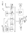
- FIG. 2 Client
- FIG. 2 illustrates a typical hardware configuration of client 110 which is representative of a hardware environment for practicing the present invention.
- Client 110 may have a central processing unit (CPU) 210 coupled to various other components by system bus 212 .
- An operating system 240 may run on CPU 210 and provide control and coordinate the functions of the various components of FIG. 2 .
- An application 250 in accordance with the principles of the present invention may run in conjunction with operating system 240 and provide calls to operating system 240 where the calls implement the various functions or services to be performed by application 250 .
- Read only memory (ROM) 216 may be coupled to system bus 212 and include a basic input/output system (“BIOS”) that controls certain basic functions of client 110 .
- BIOS basic input/output system
- RAM 214 Random access memory (RAM) 214 , I/O adapter 218 and communications adapter 234 may also be coupled to system bus 212 . It should be noted that software components including operating system 240 and application 250 may be loaded into RAM 214 which may be the computer system's main memory. I/O adapter 218 may be a small computer system interface (“SCSI”) adapter that communicates with a disk unit 220 , e.g., disk drive.
- SCSI small computer system interface
- Communications adapter 234 may interconnect bus 212 with an outside network enabling client 110 to communicate with server 120 via a Local Area Network (LAN), e.g., Ethernet, Token Ring, ARCnet or a Wide Area Network (WAN), e.g., Internet.
- LAN Local Area Network
- WAN Wide Area Network
- Input/Output devices may also be connected to system bus 212 via a user interface adapter 222 and a display adapter 236 .
- Keyboard 224 , mouse 226 and speaker 230 may all be interconnected to bus 212 through user interface adapter 222 .
- Event data may be inputted to client 110 through any of these devices.
- a display monitor 238 may be connected to system bus 212 by display adapter 236 . In this manner, a user is capable of inputting to client 110 through keyboard 224 or mouse 226 and receiving output from client 110 via display 238 or speaker 230 .
- FIG. 3 Server
- FIG. 3 illustrates a typical hardware configuration of server 120 which is representative of a hardware environment for practicing the present invention.
- Server 120 may employ a peripheral component interconnect (PCI) local bus architecture.
- PCI peripheral component interconnect
- AGP Accelerated Graphics Port
- ISA Industry Standard Architecture
- Processor 301 and main memory 302 e.g., Dynamic Random Access Memory (DRAM), Synchronous DRAM (SDRAM), may be connected to PCI local bus 303 through north bridge 304 .
- North bridge 304 may also include an integrated memory controller and cache memory for processor 301 .
- an operating system 305 may run on processor 301 to provide control and coordinate the functions of the various components of FIG. 3 .
- An application 306 in accordance with the principles of the present invention may run in conjunction with operating system 305 and provide calls to operating system 305 where the calls implement the various functions or services to be performed by operating system 305 for application 306 . It should be noted that software components including operating system 305 and application 306 may be loaded into system's main memory 302 .
- RAID controller 307 and network interface connection 308 may also be connected to PCI local bus 303 .
- RAID controller 307 may be coupled to RAID storage system 130 thereby providing an interface between server 120 and RAID storage system 130 .
- RAID controller 307 may be configured to receive requests, e.g., read/write requests, to read from or write to a particular disk in RAID storage system 130 .
- a more detailed description of RAID controller 307 is provided below in FIG. 4 .
- Network Interface controller 308 may interconnect PCI bus 303 with an outside network enabling server 120 to communicate with clients 110 or RAID storage system 130 via a Local Area Network (LAN), e.g., Ethernet, Token Ring, ARCnet or a Wide Area Network (WAN), e.g., Internet.
- LAN Local Area Network
- WAN Wide Area Network
- FIG. 3 may vary depending on the implementation.
- Other internal hardware or peripheral devices such as flash ROM (or equivalent non-volatile memory) or optical disk drives and the like, may be used in addition to or in place of the hardware depicted in FIG. 3 . It is noted that the depicted example in FIG. 3 and the above described example are not meant to imply architectural limitations.
- Implementations of the invention include implementations as a computer system programmed to execute the method or methods described herein, and as a computer program product.
- sets of instructions for executing the method or methods may be resident in main memory 302 of one or more computer systems configured generally as described above.
- the set of instructions may be stored as a computer program product in another computer memory.
- the computer program product may be stored at another computer and transmitted when desired to the user's workstation by a network or by an external network such as the Internet.
- the physical storage of the sets of instructions physically changes the medium upon which it is stored so that the medium carries computer readable information. The change may be electrical, magnetic, chemical or some other physical change.
- FIG. 4 RAID Controller
- FIG. 4 illustrates an embodiment of RAID controller 307 configured in accordance with the present invention.
- RAID controller 307 may comprise a processor 401 configured to control RAID storage system 130 .
- Processor 401 may preferably be an advanced microprocessor which may be coupled to processor bus 402 .
- code/data RAM 403 which may be utilized to temporarily store code and data utilized by processor 401 .
- ROM 404 and non-volatile memory 405 may be accessed utilizing an 8-bit bus and thus bus interface 406 may be utilized to interface those devices to processor bus 402 , which typically utilizes a 32-bit bus.
- Operational code may be stored within ROM 404 , which, as those skilled in the art will appreciate, is generally provided utilizing so-called “flash” ROM. Operational code may thereafter be fetched from ROM 404 by processor 401 upon initiation of operation to direct the operation of processor 401 to perform functions including the functions of the present invention.
- Non-volatile memory 405 may be a low power CMOS memory which is powered up for “back-up” by a battery such that the information stored in non-volatile memory 405 will not be lost when main power is terminated. Thus, non-volatile memory 405 may be utilized to store configuration data or operational code in a manner similar to that stored within ROM 404 .
- ROM 404 may generally be updated at initial power application and any changes to system configuration during operation may be stored within non-volatile memory 405 and then entered into a “device change list” which may also be stored within non-volatile memory 405 and on each disk drive within the system.
- non-volatile memory 405 may store the program for updating firmware in a disk in RAID storage system 130 implementing either a RAID level one or a RAID level five without deactivating server 120 as described in conjunction with the description of FIGS. 5-8. It is noted that the program of the present invention that updates firmware in a disk in RAID storage system 130 implementing either a RAID level one or a RAID level five without deactivating server 120 as described in conjunction with the description of FIGS.
- non-volatile memory 405 may be configured to store a table used for tracking any stripes that have been updated in the physical disk of RAID storage system 130 whose firmware is being updated as described in greater detail in conjunction with FIGS. 5-8.
- a non-volatile cache 407 may be coupled to DRAM/XOR controller 408 .
- Non-volatile cache 407 may be configured into a plurality of temporary storage positions for data. That is, non-volatile cache 407 may be configured to store a copy of the updated data to be stored in the physical disk of RAID storage system 130 whose firmware is being updated as described in greater detail in conjunction with FIGS. 7-8.
- DRAM/XOR controller 408 may be utilized to control access to random access memory and also provides a hardware implemented exclusive or (XOR) circuit which may be utilized to rapidly and efficiently calculate parity for changes in updated data as well as utilized to perform the calculations discussed in FIG. 8 .
- XOR hardware implemented exclusive or
- DRAM/XOR controller 408 may be coupled to local bus 409 . Also coupled to local bus 409 may be one or more small computer system interface (SCSI) control chips 410 . Each SCSI control chip 410 may be defined as including channels which may each support RAID storage system 130 .
- SCSI small computer system interface
- RAID controller 307 may further comprise a PCI bus adapter 411 configured to interconnect RAID controller 307 with PCI bus 303 (FIG. 3 ).
- FIG. 4 is illustrative and that FIG. 4 is not meant to imply architectural limitations.
- FIG. 5 RAID Level One
- FIG. 5 illustrates RAID storage system 130 implementing RAID level one which uses mirroring in order to store identical data on two disks.
- the disk array in RAID storage system 130 implementing RAID level one may comprise physical disks 501 A-B.
- Physical disks 501 A-B may collectively or individually be referred to as physical disk 501 .
- Each physical disk 501 may comprise a plurality of units commonly referred to as stripe units 502 A-J.
- physical disk 501 A may comprise stripe units 502 A-E.
- Physical disk 501 B may comprise stripe units 502 F-J.
- Stripe units 502 A-J may collectively or individually be referred to as stripe units 502 or stripe unit 502 , respectively.
- Each stripe unit 502 may be configured to store a predefined amount, e.g., bit(s), byte(s), of data. It is noted that each physical disk 501 may comprise any number of stripe units 502 . It is further noted that RAID level one may comprise any number of physical disks 501 and that FIG. 5 is illustrative.
- a stripe 503 A-E may refer to a group of corresponding stripe units 502 .
- stripe 503 A may include stripe units A and A′.
- Stripe 503 B may include stripe units B and B′ and so forth.
- Stripes 503 A-E may collectively or individually be referred to as stripes 503 or stripe 503 .
- the disk array in RAID storage system 130 implementing RAID level one may include logical drives which divide physical drives 501 in the disk array into logical components which may be viewed by client 110 as separate drives.
- Each logical drive may include a cross section of each of physical drives 501 .
- logical drive 504 may include stripes 503 A-E across physical drives 501 A-B.
- FIG. 6 Method for Updating Firmware on a Disk In a RAID Level One System
- FIG. 6 is a flowchart of one embodiment of the present invention of a method 600 for updating firmware on a disk in RAID storage system 130 implementing a RAID level one system without deactivating server 120 .
- each disk in the disk array of a RAID may store firmware where firmware may refer to software that may be burned into a memory chip, e.g., Read Only Memory (ROM), Programmable ROM (PROM), Erasable PROM (EPROM), Electrical EPROM (EEPROM), or into the hard drive.
- firmware may refer to software that may be burned into a memory chip, e.g., Read Only Memory (ROM), Programmable ROM (PROM), Erasable PROM (EPROM), Electrical EPROM (EEPROM), or into the hard drive.
- ROM Read Only Memory
- PROM Programmable ROM
- EPROM Erasable PROM
- EEPROM Electrical EPROM
- Method 600 is a method for updating firmware on a disk in RAID storage system 130 implementing a RAID level one system without deactivating server 120 .
- a particular physical disk 501 e.g., physical disk 501 A, in RAID storage system 130 (FIGS. 1 and 3) implementing a RAID level one system may be selected to update the firmware in that particular disk 501 .
- the selected disk 501 e.g., physical disk 501 A, as well as the associated logical drives 504 (FIG. 5) enter a degrade mode of operation.
- RAID controller 307 may suppress particular activities, e.g., recovery actions, hot spare kickin, from occurring on selected disk 501 as well as prevent requests, e.g., read/write requests issued from client 110 (FIG. 1 ), hot swap queries, from reaching selected disk 501 .
- activity on the selected disk 501 may become inactive thereby allowing the firmware on the selected disk 501 to be updated.
- step 603 the firmware on the selected disk 501 , e.g., physical disk 501 A, may be updated.
- step 604 a determination may be made as to whether RAID controller 307 received any read requests for stripe units 502 in the selected disk 501 , e.g., physical disk 501 A.
- RAID controller 307 may retrieve and transmit the requested data stored in stripe unit 502 , e.g., stripe unit 502 F, that mirrors stripe unit 502 , e.g., stripe unit 502 A, containing the requested data.
- RAID controller 307 may retrieve and transmit the data labeled “A′” in stripe unit 502 F that mirrors stripe unit 502 A.
- RAID controller 307 did not receive a request to read data stored in stripe unit 502 , e.g., stripe unit 502 A, in the selected disk 501 , e.g., physical disk 501 A, then, in step 606 , a determination may be made as to whether RAID controller 307 received any write requests for stripe units 502 in selected disk 501 , e.g., physical disk 501 A.
- step 610 If RAID controller 307 did not receive any write requests for stripe units 502 in selected disk 501 , e.g., physical disk 501 A, then a determination may be made in step 610 as to whether the updating of the firmware is complete as discussed further below.
- RAID controller 307 may write the updated data in stripe unit 502 , e.g., stripe unit 502 F, that mirrors stripe unit 502 , e.g., stripe unit 502 A, containing the data that was updated.
- RAID controller 307 may write over the data labeled “A′” in stripe unit 502 F that mirrors stripe unit 502 A to store the updated data. If client 110 , e.g., client 110 A, requested to write over the data labeled “D” in stripe unit 502 A during updating of the firmware on physical disk 501 A, then RAID controller 307 may write over the data labeled “D′” in stripe unit 502 D that mirrors stripe unit 502 A to store the updated data.
- a copy of the updated data may be stored for backup purposes.
- a copy of the updated data may be stored in a non-volatile cache 407 (FIG. 4) in RAID controller 307 .
- stripe 503 e.g., stripe 503 A, stripe 503 D, associated with stripe units 502 , e.g., stripe unit 502 A, stripe unit 502 D, in the selected disk 501 , e.g., physical disk 501 A, whose data was changed may be tracked.
- stripes 503 associated with stripe units 502 in the selected disk 501 whose data was changed may be tracked in a table stored in non-volatile memory 405 (FIG. 4) of RAID controller 307 .
- the stripe units 502 in the selected disk 501 e.g., physical disk 501 A, associated with any stripes to be updated, may be rebuilt as described further below in steps 613 - 619 .
- step 611 a determination may be made as to whether any stripes 503 were updated. If there were no stripes 503 updated, then, in step 612 , there is no need to rebuild any stripe units 502 , e.g., stripe units 502 A-E, in the selected disk 501 , e.g., disk 501 A.
- a stripe unit 502 e.g., stripe unit 502 A, associated with a stripe 503 updated may be rebuilt in step 613 .
- stripe units 502 e.g., stripe unit 502 A, in the selected disk 501 , e.g., disk 501 A, associated with stripes 503 that have been updated may be rebuilt stripe by stripe 503 updated, e.g., stripe 503 A, stripe 503 D, starting from the top stripe 503 that was updated, e.g., stripe 503 A, to the bottom stripe 503 , e.g., stripe 503 D, if any, that was updated.
- the stripe unit 502 e.g., stripe unit 502 A, associated with a stripe 503 updated may be rebuilt by copying data in the stripe unit 502 , e.g., stripe unit 502 F, that mirrors the stripe unit 502 , e.g., stripe unit 502 A, to be rebuilt and storing that data in the stripe unit 502 , e.g., stripe unit 502 A, to be rebuilt.
- each stripe 503 e.g., stripe 503 A, associated with the stripe unit 502 , e.g., stripe unit 502 A, rebuilt may be tracked.
- stripes 503 associated with stripe units 502 rebuilt may be tracked in a table stored in non-volatile memory 405 in RAID controller 307 .
- a determination may be made as to whether RAID controller 307 received a write request for a stripe unit 502 , e.g., stripe unit 502 A, rebuilt in the selected disk 501 , e.g., disk 501 A, prior to completing the rebuilding of all stripe units 502 required to be rebuilt.
- RAID controller 307 did not receive a write request for a stripe unit 502 , e.g., stripe unit 502 A, rebuilt in the selected disk 501 , e.g., disk 501 A, prior to completing the rebuilding of all stripe units 502 , e.g., stripe unit 502 D, required to be rebuilt, then, in step 617 , a determination may be made as to whether another disk 501 in the disk array of RAID storage system 130 has become inoperative during the process of rebuilding the stripe units 502 in the selected disk 501 required to be rebuilt as discussed further below.
- RAID controller 307 received a write request for a stripe unit 502 , e.g., stripe unit 502 A, rebuilt in the selected disk 501 , e.g., disk 501 A, prior to completing the rebuilding of all stripe units 502 , e.g., stripe unit 502 D, required to be rebuilt, then, in step 616 , the updated data may be written in both the stripe unit 502 , e.g., stripe unit 502 A, rebuilt in the selected disk 501 , e.g., disk 501 A, and in the stripe unit 502 , e.g., stripe unit 502 F, that mirrors the stripe unit 502 , e.g., stripe unit 502 A, rebuilt.
- stripe units 502 A and 502 D need to be updated with the updated data. If after stripe unit 502 A is updated and prior to stripe unit 502 D being updated, a request to write data to stripe unit 502 A is received, then RAID controller 307 may write the updated data in stripe unit 502 , e.g., stripe unit 502 A, already rebuilt in selected disk 501 , e.g., disk 501 A, as well as in the stripe unit 502 , e.g., stripe unit 502 F, that mirrors the stripe unit 502 , e.g., stripe unit 502 A, rebuilt whose data was overwritten with the updated data.
- a determination may be made as to whether another disk 501 in the disk array of RAID storage system 130 has become inoperative during the process of rebuilding the stripe units 502 in selected disk 501 required to be rebuilt.
- step 619 a determination may be made in step 619 as to whether the rebuilding of the stripe units 502 , e.g., stripe units 502 A, stripe units 502 D, whose data has changed has been completed as discussed further below.
- the stripe units 502 e.g., stripe units 502 A, stripe units 502 D, in the selected disk 501 , e.g., disk 501 A, required to be rebuilt may be rebuilt, in step 618 , using a copy of the updated data stored for backup purposes in step 608 .
- step 619 a determination may be made as to whether the rebuilding of the stripe units 502 , e.g., stripe units 502 A, stripe units 502 D, whose data has changed has been completed. If not, then the next stripe unit 502 , e.g., stripe unit 502 D, required to be rebuilt may be rebuilt in step 613 . If the rebuilding of the stripe units 502 , e.g., stripe units 502 A, stripe units 502 D, in the selected disk 501 , e.g., physical disk 501 A, whose data has changed has been completed, then method 600 may be terminated in step 620 .
- the selected disk 501 e.g., physical disk 501 A
- method 600 describes a method for updating firmware on a disk in RAID storage system 130 implementing a RAID level one system without deactivating RAID controller 307 that the principles described in method 600 may be applicable to any redundant RAID level. It is further noted that a person of ordinary skill would be capable of applying the principles taught in method 600 to any redundant RAID level. It is further noted that method 600 may be executed in a different order presented and that the order presented in the discussion of FIG. 6 is illustrative. It is further noted that certain steps in method 600 may be executed almost concurrently.
- FIG. 7 RAID Level Five
- FIG. 7 illustrates RAID storage system 130 implementing RAID level five where RAID level five uses data interleaving by striping data across all disks and provides for error correction by distributing parity data across all disks.
- the disk array in RAID storage system 130 implementing RAID level five may comprise a plurality of physical disks 701 A-D configured to store data including parity data. Physical disks 701 A-D may collectively or individually be referred to as physical disks 701 or physical disk 701 . It is noted that the disk array of RAID storage system 130 implementing RAID level five may comprise any number of physical disks 701 and that FIG. 7 is illustrative.
- Each physical disk 701 may comprise a plurality of units commonly referred to as stripe units 702 A-L.
- physical disk 701 A may comprise stripe units 702 A-C.
- Physical disk 701 B may comprise stripe units 702 D-F and so forth.
- Stripe units 702 A-L may collectively or individually be referred to as stripe units 702 or stripe unit 702 , respectively.
- Each stripe unit 702 may be configured to store a predefined amount, e.g., bit(s), byte(s), of data including parity data.
- Stripe units 702 that are labeled with a “D” refers to stripe units 702 that store non-parity data.
- Stripe units 702 that are labeled with a “P” refers to stripe units 702 that store parity data. It is noted that each physical disk 701 may comprise any number of stripe units 702 .
- a stripe 703 A-C may refer to a group of corresponding stripe units 702 .
- stripe 703 A may include stripe units D 1 , D 2 , D 3 and P 1 .
- Stripe 703 B may include stripe units P 2 , D 4 , D 5 and D 6 .
- Stripe 703 C may include stripe units D 7 , P 3 , D 8 and D 9 .
- Stripes 703 A-C may collectively or individually be referred to as stripes 703 or stripe 703 .
- the disk array in RAID storage system 130 may include logical drives which divide physical drives 701 in the disk array into logical components which may be viewed by client 110 as separate drives.
- Each logical drive may include a cross section of each of physical drives 701 .
- logical drive 704 may include stripes 703 A-C across physical drives 701 A-D.
- FIG. 8 Method for Updating Firmware on a Disk In a RAID Level Five System
- FIG. 8 is a flowchart of one embodiment of the present invention of a method 800 for updating firmware on a disk in RAID storage system 130 implementing a RAID level five system without deactivating server 120 .
- a particular physical disk 701 e.g., physical disk 701 A, in RAID storage system 130 (FIGS. 1 and 3) implementing a RAID level five system may be selected to update the firmware in that particular disk 501 .
- the selected disk 701 may enter a degrade mode of operation.
- RAID controller 307 may suppress particular activities, e.g., recovery actions, hot spare kickin, from occurring on the selected disk 701 as well as prevent requests, e.g., read/write requests issued from client 110 (FIG. 1 ), hot swap queries, from reaching the selected disk 701 .
- activity on the selected disk 701 may become inactive thereby allowing the firmware on the selected disk 701 to be updated.
- step 803 the firmware on the selected disk 701 , e.g., physical disk 701 A, may be updated.
- step 804 a determination may be made as to whether RAID controller 307 received any read requests for stripe units 702 in the selected disk 701 , e.g., physical disk 701 A.
- RAID controller 307 may perform a logical calculation on data, e.g., D 2 , D 3 and P 1 , located in other stripe units 702 , e.g., stripe units 702 D, 702 G and 702 J, of stripe 703 , e.g., stripe 703 A, associated with the stripe unit 702 , e.g., stripe unit 702 A, containing the data requested.
- the logical calculation may be an exclusive or (XOR) calculation performed by DRAM/XOR controller 408 (FIG. 4 ).
- XOR exclusive or
- the data requested in stripe unit 702 e.g., stripe unit 702 A
- the selected disk 701 e.g., physical disk 701 A
- the resulting data may then be transmitted to the requesting client 110 in step 806 .
- step 807 a determination may be made as to whether RAID controller 307 received any write requests for stripe units 702 in the selected disk 701 , e.g., physical disk 701 A. Furthermore, upon transmitting the requested data in step 806 , a determination may be made in step 807 as to whether RAID controller 307 received any write requests for stripe units 702 in the selected disk 701 , e.g., physical disk 701 A.
- step 812 a determination may be made in step 812 as to whether the updating of the firmware is complete as discussed further below.
- RAID controller 307 may generate a new parity for the stripe 703 , e.g., stripe 703 A, associated with stripe unit 702 , e.g., stripe unit 702 A, containing outdated data.
- a new parity for the stripe 703 , e.g., stripe 703 A, associated with the stripe unit 702 , e.g., stripe unit 702 A, containing outdated data may be generated so that the updated data may replace the outdated data as explained further below.
- a new parity P 1 may be generated for stripe 703 A associated with stripe unit 702 A.
- a new parity may be generated by performing a logical operation on the data to be written along with the data stored in other stripe units 702 , e.g., stripe unit 702 B, stripe unit 702 C, except the stripe unit 702 , e.g., stripe unit 702 J, storing the parity data to be updated and the stripe unit 702 , e.g., stripe unit 702 A, of the selected disk 701 , e.g., disk 701 A, whose firmware is being updated.
- the logical calculation may be an exclusive or (XOR) calculation performed by DRAM/XOR controller 408 .
- XOR exclusive or
- the logical calculation may be an exclusive or (XOR) calculation performed by DRAM/XOR controller 408 .
- XOR exclusive or
- a new parity may be generated for P 1 by performing the XOR function on X, D 2 and D 3 .
- the updated parity may then replace the older parity associated the stripe 703 , e.g., 703 A, updated in step 809 .
- a copy of the updated data i.e., the data requested to be written in stripe units 702 in the selected disk 701
- a copy of the updated data may be stored for backup purposes.
- a copy of the updated data may be stored in either a non-volatile cache 407 (FIG. 4) in RAID controller 307 or in a special storage area typically called a log area in a limited number, e.g., two, of other drives 701 , e.g., disk 701 B, disk 701 C. It is noted for clarity that each drive 701 may be capable of containing a special storage area typically called a log area.
- stripe 703 e.g., stripe 703 A, associated with stripe unit 702 , e.g., stripe unit 702 A, in the selected disk 701 , e.g., physical disk 701 A, whose data was changed may be tracked.
- stripes 703 associated with stripe units 702 in selected disk 701 whose data was changed may be tracked in a table stored in non-volatile memory 405 (FIG. 4) of RAID controller 307 .
- the stripe units 702 in the selected disk 701 e.g., physical disk 701 A, associated with any stripes to be updated, may be rebuilt as described further below in steps 813 - 818 .
- step 813 a determination may be made as to whether any stripes 703 were updated. If there were no stripes 703 updated, then, in step 814 , there is no need to rebuild any stripe units 702 , e.g., stripe units 702 A-C, in the selected disk 701 , e.g., disk 701 A.
- stripe units 702 e.g., stripe units 702 A-C
- a stripe unit 702 e.g., stripe unit 702 A, associated with a stripe 703 updated may be rebuilt in step 815 .
- stripe units 702 e.g., stripe unit 702 A, in the selected disk 701 , e.g., disk 701 A, associated with stripes 703 that have been updated may be rebuilt stripe by stripe 703 updated, e.g., stripe 703 A, starting from the top stripe 703 that was updated, e.g., stripe 703 A, to the bottom stripe 703 , if any, that was updated.
- the stripe unit 702 e.g., stripe unit 702 A, associated with a stripe 703 updated may be rebuilt by performing a logical calculation on data, e.g., D 2 , D 3 and P 1 , located in other stripe units 702 , e.g., stripe units 702 D, 702 G and 702 J, of stripe 703 , e.g., stripe 703 A, associated with the stripe unit 702 , e.g., stripe unit 702 A, containing the outdated data.
- the logical calculation may be an exclusive or (XOR) calculation performed by DRAM/XOR controller 408 .
- the updated data to be inserted in the stripe unit 702 , e.g., stripe unit 702 A, in the selected disk 701 , e.g., physical disk 701 A, to be rebuilt may be calculated by performing the XOR function on D 2 , D 3 and P 1 .
- the resulting data may then be inserted in the stripe unit 702 , e.g., stripe unit 703 A, to be rebuilt.
- step 816 a determination may be made as to whether another disk 501 in the disk array of RAID storage system 130 has become inoperative during the process of rebuilding the stripe units 702 in the selected disk 701 required to be rebuilt.
- step 818 a determination may be made in step 818 as to whether the rebuilding of the stripe units 702 , e.g., stripe units 502 A, whose data has changed has been completed as discussed further below.
- the stripe units 702 e.g., stripe units 702 A, in the selected disk 701 , e.g., disk 701 A, required to be rebuilt may be rebuilt, in step 817 , using a copy of the updated data stored for backup purposes in step 810 .
- step 818 a determination may be made as to whether the rebuilding of the stripe units 702 , e.g., stripe units 702 A, whose data has changed has been completed. If not, then the next stripe unit 702 , e.g., stripe unit 702 B, required to be rebuilt may be rebuilt in step 815 . If the rebuilding of the stripe units 702 , e.g., stripe units 702 A, in the selected disk 701 , e.g., physical disk 701 A, whose data has changed has been completed, then method 800 may be terminated in step 819 .
- method 800 describes a method for updating firmware on a disk in RAID storage system 130 implementing a RAID level five system without deactivating server 120 that the principles described in method 800 may be applicable to any redundant RAID level. It is further noted that a person of ordinary skill would be capable of applying the principles taught in method 800 to any redundant RAID level. It is further noted that method 800 may be executed in a different order presented and that the order presented in the discussion of FIG. 8 is illustrative. It is further noted that certain steps in method 800 may be executed almost concurrently.
Abstract
Description
Claims (81)
Priority Applications (1)
| Application Number | Priority Date | Filing Date | Title |
|---|---|---|---|
| US10/085,401 US6728833B2 (en) | 2002-02-28 | 2002-02-28 | Upgrading firmware on disks of the raid storage system without deactivating the server |
Applications Claiming Priority (1)
| Application Number | Priority Date | Filing Date | Title |
|---|---|---|---|
| US10/085,401 US6728833B2 (en) | 2002-02-28 | 2002-02-28 | Upgrading firmware on disks of the raid storage system without deactivating the server |
Publications (2)
| Publication Number | Publication Date |
|---|---|
| US20030163640A1 US20030163640A1 (en) | 2003-08-28 |
| US6728833B2 true US6728833B2 (en) | 2004-04-27 |
Family
ID=27753619
Family Applications (1)
| Application Number | Title | Priority Date | Filing Date |
|---|---|---|---|
| US10/085,401 Expired - Lifetime US6728833B2 (en) | 2002-02-28 | 2002-02-28 | Upgrading firmware on disks of the raid storage system without deactivating the server |
Country Status (1)
| Country | Link |
|---|---|
| US (1) | US6728833B2 (en) |
Cited By (23)
| Publication number | Priority date | Publication date | Assignee | Title |
|---|---|---|---|---|
| US20030005354A1 (en) * | 2001-06-28 | 2003-01-02 | International Business Machines Corporation | System and method for servicing requests to a storage array |
| US20030217257A1 (en) * | 2002-05-17 | 2003-11-20 | Ebsen David S. | Method for updating memory resident firmware as a background operation |
| US20040019752A1 (en) * | 2002-07-29 | 2004-01-29 | Burton David Alan | Method and system for upgrading drive firmware in a non-disruptive manner |
| US20040250161A1 (en) * | 2003-06-09 | 2004-12-09 | Brian Patterson | Method and apparatus for data reconstruction |
| US20050033933A1 (en) * | 2003-08-04 | 2005-02-10 | Hetrick William A. | Systems and methods for modifying disk drive firmware in a raid storage system |
| US20050044278A1 (en) * | 2003-08-22 | 2005-02-24 | International Business Machines Corporation | Apparatus and method to activate transparent data storage drive firmware updates |
| US20050155029A1 (en) * | 2004-01-09 | 2005-07-14 | Dell Products L.P. | System and method for updating firmware of a storage drive in a storage network |
| US20060053214A1 (en) * | 2004-06-29 | 2006-03-09 | International Business Machines Corporation | Method and system of detecting a change in a server in a server system |
| US20060059305A1 (en) * | 2004-09-13 | 2006-03-16 | Fisher James A | Efficient firmware update for hierarchical data storage systems |
| US20060149900A1 (en) * | 2004-12-15 | 2006-07-06 | Dell Products L.P | Intelligent hotspare or "SmartSpare" drive with pre-emptive drive rebuild |
| US20060161821A1 (en) * | 2005-01-14 | 2006-07-20 | Microsoft Corporation | Increasing software fault tolerance by employing surprise-removal paths |
| US20060259756A1 (en) * | 2005-05-12 | 2006-11-16 | Thompson Mark J | System and method for reflashing disk drive firmware |
| US20060277328A1 (en) * | 2005-06-06 | 2006-12-07 | Dell Products L.P. | System and method for updating the firmware of a device in a storage network |
| US7340642B1 (en) * | 2004-04-30 | 2008-03-04 | Network Appliance, Inc. | Method and an apparatus to maintain storage devices in a storage system |
| US20090210867A1 (en) * | 2008-02-18 | 2009-08-20 | Ryo Suzuki | Disk array apparatus, method for exchanging firmware, program for exchanging firmware and storage medium for storing program thereof |
| US20090228648A1 (en) * | 2008-03-04 | 2009-09-10 | International Business Machines Corporation | High performance disk array rebuild |
| US7594075B2 (en) | 2004-10-20 | 2009-09-22 | Seagate Technology Llc | Metadata for a grid based data storage system |
| US20090292873A1 (en) * | 2008-05-23 | 2009-11-26 | Fujitsu Limited | Disk array apparatus, method for application of control firmware, and controlling unit for controlling application of control firmware |
| US20090313617A1 (en) * | 2008-06-12 | 2009-12-17 | Infortrend Technology, Inc. | Method for Updating Control Program of Physical Storage Device in Storage Virtualization System and Storage Virtualization Controller and System Thereof |
| US7979593B2 (en) | 2005-06-08 | 2011-07-12 | International Business Machines Corporation | Non-disruptive library reset method |
| US20110238913A1 (en) * | 2008-10-29 | 2011-09-29 | Takehiko Kurashige | Disk array control device and storage device |
| US20130263105A1 (en) * | 2012-03-30 | 2013-10-03 | Lenovo (Singapore) Pte. Ltd. | Methods for facilitating updates at an information handling device |
| US8966466B2 (en) | 2012-04-04 | 2015-02-24 | Avago Technologies General Ip (Singapore) Pte. Ltd. | System for performing firmware updates on a number of drives in an array with minimum interruption to drive I/O operations |
Families Citing this family (12)
| Publication number | Priority date | Publication date | Assignee | Title |
|---|---|---|---|---|
| CN100372294C (en) * | 2004-02-04 | 2008-02-27 | 华为技术有限公司 | Appratus upgrading method |
| US20070067563A1 (en) * | 2005-09-19 | 2007-03-22 | Lsi Logic Corporation | Updating disk drive firmware behind RAID controllers |
| US8626871B2 (en) * | 2010-05-19 | 2014-01-07 | Cleversafe, Inc. | Accessing a global vault in multiple dispersed storage networks |
| KR101254875B1 (en) * | 2011-05-18 | 2013-04-15 | 삼성에스디아이 주식회사 | Battery pack management system |
| KR20130050588A (en) * | 2011-11-08 | 2013-05-16 | 주식회사 히타치엘지 데이터 스토리지 코리아 | Apparatus and method for recovering embedded system firmware of nas server |
| US9798534B1 (en) * | 2015-07-01 | 2017-10-24 | EMC IP Holding Company LLC | Method and system to perform non-intrusive online disk firmware upgrades |
| JP6912163B2 (en) * | 2016-03-17 | 2021-07-28 | 日本電気株式会社 | Firmware boot device, firmware boot method, and firmware boot program |
| US10503491B2 (en) | 2016-09-16 | 2019-12-10 | Honeywell International Inc. | On-process migration of non-redundant input/output (I/O) firmware |
| CN107168707A (en) * | 2017-05-12 | 2017-09-15 | 郑州云海信息技术有限公司 | A kind of method for automatically updating all outer plug-in card device drives of Linux system |
| US10860305B1 (en) * | 2017-09-29 | 2020-12-08 | Amazon Technologies, Inc. | Secure firmware deployment |
| CN109213509A (en) * | 2018-08-31 | 2019-01-15 | 郑州云海信息技术有限公司 | A kind of upgrade method of RAID card, upgrade-system and relevant apparatus |
| KR20210023184A (en) * | 2019-08-22 | 2021-03-04 | 에스케이하이닉스 주식회사 | Apparatus and method for managing firmware through runtime overlay |
Citations (4)
| Publication number | Priority date | Publication date | Assignee | Title |
|---|---|---|---|---|
| US6058489A (en) | 1995-10-13 | 2000-05-02 | Compaq Computer Corporation | On-line disk array reconfiguration |
| US6105089A (en) * | 1997-05-13 | 2000-08-15 | Micron Electronics, Inc. | Data management system for adding or exchanging components on a running computer |
| US20020166027A1 (en) * | 2001-04-20 | 2002-11-07 | Hitachi, Ltd. | Updating method of firmware of hard disk unit mounted on disk array device and disk array device with function for performing updating method |
| US20030212856A1 (en) * | 2002-05-08 | 2003-11-13 | Nichols Charles E. | Method and apparatus for upgrading disk drive firmware in a RAID storage system |
-
2002
- 2002-02-28 US US10/085,401 patent/US6728833B2/en not_active Expired - Lifetime
Patent Citations (4)
| Publication number | Priority date | Publication date | Assignee | Title |
|---|---|---|---|---|
| US6058489A (en) | 1995-10-13 | 2000-05-02 | Compaq Computer Corporation | On-line disk array reconfiguration |
| US6105089A (en) * | 1997-05-13 | 2000-08-15 | Micron Electronics, Inc. | Data management system for adding or exchanging components on a running computer |
| US20020166027A1 (en) * | 2001-04-20 | 2002-11-07 | Hitachi, Ltd. | Updating method of firmware of hard disk unit mounted on disk array device and disk array device with function for performing updating method |
| US20030212856A1 (en) * | 2002-05-08 | 2003-11-13 | Nichols Charles E. | Method and apparatus for upgrading disk drive firmware in a RAID storage system |
Cited By (43)
| Publication number | Priority date | Publication date | Assignee | Title |
|---|---|---|---|---|
| US20030005354A1 (en) * | 2001-06-28 | 2003-01-02 | International Business Machines Corporation | System and method for servicing requests to a storage array |
| US6820211B2 (en) * | 2001-06-28 | 2004-11-16 | International Business Machines Corporation | System and method for servicing requests to a storage array |
| US20030217257A1 (en) * | 2002-05-17 | 2003-11-20 | Ebsen David S. | Method for updating memory resident firmware as a background operation |
| US7380113B2 (en) * | 2002-05-17 | 2008-05-27 | Xiotech Corporation | Method for updating memory resident firmware as a background operation |
| US20040019752A1 (en) * | 2002-07-29 | 2004-01-29 | Burton David Alan | Method and system for upgrading drive firmware in a non-disruptive manner |
| US6907504B2 (en) * | 2002-07-29 | 2005-06-14 | International Business Machines Corporation | Method and system for upgrading drive firmware in a non-disruptive manner |
| US20040250161A1 (en) * | 2003-06-09 | 2004-12-09 | Brian Patterson | Method and apparatus for data reconstruction |
| US7308599B2 (en) * | 2003-06-09 | 2007-12-11 | Hewlett-Packard Development Company, L.P. | Method and apparatus for data reconstruction after failure of a storage device in a storage array |
| US20050033933A1 (en) * | 2003-08-04 | 2005-02-10 | Hetrick William A. | Systems and methods for modifying disk drive firmware in a raid storage system |
| US20050044278A1 (en) * | 2003-08-22 | 2005-02-24 | International Business Machines Corporation | Apparatus and method to activate transparent data storage drive firmware updates |
| US6996635B2 (en) * | 2003-08-22 | 2006-02-07 | International Business Machines Corporation | Apparatus and method to activate transparent data storage drive firmware updates |
| US20050155029A1 (en) * | 2004-01-09 | 2005-07-14 | Dell Products L.P. | System and method for updating firmware of a storage drive in a storage network |
| US7231493B2 (en) * | 2004-01-09 | 2007-06-12 | Dell Products L.P. | System and method for updating firmware of a storage drive in a storage network |
| US7340642B1 (en) * | 2004-04-30 | 2008-03-04 | Network Appliance, Inc. | Method and an apparatus to maintain storage devices in a storage system |
| US20060053214A1 (en) * | 2004-06-29 | 2006-03-09 | International Business Machines Corporation | Method and system of detecting a change in a server in a server system |
| US7444341B2 (en) * | 2004-06-29 | 2008-10-28 | International Business Machines Corporation | Method and system of detecting a change in a server in a server system |
| US20060059305A1 (en) * | 2004-09-13 | 2006-03-16 | Fisher James A | Efficient firmware update for hierarchical data storage systems |
| US7404184B2 (en) * | 2004-09-13 | 2008-07-22 | International Business Machines Corporation | Efficient firmware update for hierarchical data storage systems |
| US7594075B2 (en) | 2004-10-20 | 2009-09-22 | Seagate Technology Llc | Metadata for a grid based data storage system |
| US7587626B2 (en) | 2004-12-15 | 2009-09-08 | Dell Products L.P. | Intelligent hotspare or “SmartSpare” drive with pre-emptive drive rebuild |
| US20060149900A1 (en) * | 2004-12-15 | 2006-07-06 | Dell Products L.P | Intelligent hotspare or "SmartSpare" drive with pre-emptive drive rebuild |
| US8006120B2 (en) | 2005-01-14 | 2011-08-23 | Microsoft Corporation | Increasing software fault tolerance by employing surprise-removal paths |
| US20060161821A1 (en) * | 2005-01-14 | 2006-07-20 | Microsoft Corporation | Increasing software fault tolerance by employing surprise-removal paths |
| US7366944B2 (en) | 2005-01-14 | 2008-04-29 | Microsoft Corporation | Increasing software fault tolerance by employing surprise-removal paths |
| US20080294932A1 (en) * | 2005-01-14 | 2008-11-27 | Microsoft Corporation | Increasing software fault tolerance by employing surprise-removal paths |
| US7426633B2 (en) * | 2005-05-12 | 2008-09-16 | Hewlett-Packard Development Company, L.P. | System and method for reflashing disk drive firmware |
| US20060259756A1 (en) * | 2005-05-12 | 2006-11-16 | Thompson Mark J | System and method for reflashing disk drive firmware |
| US7558915B2 (en) * | 2005-06-06 | 2009-07-07 | Dell Products L.P. | System and method for updating the firmware of a device in a storage network |
| US20060277328A1 (en) * | 2005-06-06 | 2006-12-07 | Dell Products L.P. | System and method for updating the firmware of a device in a storage network |
| US7979593B2 (en) | 2005-06-08 | 2011-07-12 | International Business Machines Corporation | Non-disruptive library reset method |
| US20090210867A1 (en) * | 2008-02-18 | 2009-08-20 | Ryo Suzuki | Disk array apparatus, method for exchanging firmware, program for exchanging firmware and storage medium for storing program thereof |
| US8051415B2 (en) * | 2008-02-18 | 2011-11-01 | Nec Corporation | Disk array apparatus, method for exchanging firmware, program for exchanging firmware and storage medium for storing program thereof |
| US20090228648A1 (en) * | 2008-03-04 | 2009-09-10 | International Business Machines Corporation | High performance disk array rebuild |
| US7970994B2 (en) | 2008-03-04 | 2011-06-28 | International Business Machines Corporation | High performance disk array rebuild |
| US20090292873A1 (en) * | 2008-05-23 | 2009-11-26 | Fujitsu Limited | Disk array apparatus, method for application of control firmware, and controlling unit for controlling application of control firmware |
| US8312211B2 (en) * | 2008-05-23 | 2012-11-13 | Fujitsu Limited | Disk array apparatus, method for application of control firmware, and controlling unit for controlling application of control firmware |
| US20090313617A1 (en) * | 2008-06-12 | 2009-12-17 | Infortrend Technology, Inc. | Method for Updating Control Program of Physical Storage Device in Storage Virtualization System and Storage Virtualization Controller and System Thereof |
| US8356292B2 (en) | 2008-06-12 | 2013-01-15 | Infortrend Technology, Inc. | Method for updating control program of physical storage device in storage virtualization system and storage virtualization controller and system thereof |
| US20110238913A1 (en) * | 2008-10-29 | 2011-09-29 | Takehiko Kurashige | Disk array control device and storage device |
| US8433882B2 (en) * | 2008-10-29 | 2013-04-30 | Kabushiki Kaisha Toshiba | Disk array control device and storage device |
| US20130263105A1 (en) * | 2012-03-30 | 2013-10-03 | Lenovo (Singapore) Pte. Ltd. | Methods for facilitating updates at an information handling device |
| US8935688B2 (en) * | 2012-03-30 | 2015-01-13 | Lenovo (Singapore) Pte. Ltd. | Methods for facilitating updates at an information handling device |
| US8966466B2 (en) | 2012-04-04 | 2015-02-24 | Avago Technologies General Ip (Singapore) Pte. Ltd. | System for performing firmware updates on a number of drives in an array with minimum interruption to drive I/O operations |
Also Published As
| Publication number | Publication date |
|---|---|
| US20030163640A1 (en) | 2003-08-28 |
Similar Documents
| Publication | Publication Date | Title |
|---|---|---|
| US6728833B2 (en) | Upgrading firmware on disks of the raid storage system without deactivating the server | |
| US7120826B2 (en) | Partial mirroring during expansion thereby eliminating the need to track the progress of stripes updated during expansion | |
| US6041423A (en) | Method and apparatus for using undo/redo logging to perform asynchronous updates of parity and data pages in a redundant array data storage environment | |
| US5379417A (en) | System and method for ensuring write data integrity in a redundant array data storage system | |
| US8839028B1 (en) | Managing data availability in storage systems | |
| US7231493B2 (en) | System and method for updating firmware of a storage drive in a storage network | |
| JP3283530B2 (en) | Validation system for maintaining parity integrity in disk arrays | |
| US7386758B2 (en) | Method and apparatus for reconstructing data in object-based storage arrays | |
| JP2959901B2 (en) | Redundant array of storage device and online reconfiguration method | |
| US6990611B2 (en) | Recovering data from arrays of storage devices after certain failures | |
| JP3071017B2 (en) | Method and control system for restoring redundant information in redundant array system | |
| US9104342B2 (en) | Two stage checksummed raid storage model | |
| JP2951676B2 (en) | File system for multiple storage classes | |
| US7577866B1 (en) | Techniques for fault tolerant data storage | |
| US20120192037A1 (en) | Data storage systems and methods having block group error correction for repairing unrecoverable read errors | |
| US20060236149A1 (en) | System and method for rebuilding a storage disk | |
| US20030237019A1 (en) | Using file system information in RAID data reconstruction and migration | |
| JP2006505035A (en) | Methods and means that can be used in the event of multiple dependent failures or any double disk failures in a disk array | |
| JPH06504863A (en) | Storage array with copyback cache | |
| US8132044B1 (en) | Concurrent and incremental repair of a failed component in an object based storage system for high availability | |
| US7426655B2 (en) | System and method of enhancing storage array read performance using a spare storage array | |
| US6446220B1 (en) | Updating data and parity data with and without read caches | |
| US20060041782A1 (en) | System and method for recovering from a drive failure in a storage array | |
| US10095585B1 (en) | Rebuilding data on flash memory in response to a storage device failure regardless of the type of storage device that fails | |
| JP5776436B2 (en) | Storage system, storage control device, and storage control method |
Legal Events
| Date | Code | Title | Description |
|---|---|---|---|
| AS | Assignment |
Owner name: INTERNATIONAL BUSINESS MACHINES CORPORATION, NEW Y Free format text: ASSIGNMENT OF ASSIGNORS INTEREST;ASSIGNORS:PRUETT, GREGORY B.;RHOADES, DAVID B.;RIEDLE, LINDA A.;REEL/FRAME:012659/0966;SIGNING DATES FROM 20020215 TO 20020222 |
|
| FEPP | Fee payment procedure |
Free format text: PAYOR NUMBER ASSIGNED (ORIGINAL EVENT CODE: ASPN); ENTITY STATUS OF PATENT OWNER: LARGE ENTITY |
|
| STCF | Information on status: patent grant |
Free format text: PATENTED CASE |
|
| FPAY | Fee payment |
Year of fee payment: 4 |
|
| AS | Assignment |
Owner name: GOOGLE INC., CALIFORNIA Free format text: ASSIGNMENT OF ASSIGNORS INTEREST;ASSIGNOR:INTERNATIONAL BUSINESS MACHINES CORPORATION;REEL/FRAME:026894/0001 Effective date: 20110817 |
|
| FPAY | Fee payment |
Year of fee payment: 8 |
|
| FPAY | Fee payment |
Year of fee payment: 12 |
|
| AS | Assignment |
Owner name: GOOGLE LLC, CALIFORNIA Free format text: CHANGE OF NAME;ASSIGNOR:GOOGLE INC.;REEL/FRAME:044127/0735 Effective date: 20170929 |