US6731728B2 - Low noise line powered DAA with differential feedback - Google Patents
Low noise line powered DAA with differential feedback Download PDFInfo
- Publication number
- US6731728B2 US6731728B2 US09/055,991 US5599198A US6731728B2 US 6731728 B2 US6731728 B2 US 6731728B2 US 5599198 A US5599198 A US 5599198A US 6731728 B2 US6731728 B2 US 6731728B2
- Authority
- US
- United States
- Prior art keywords
- telephone line
- line
- shunt regulator
- modulator
- power
- Prior art date
- Legal status (The legal status is an assumption and is not a legal conclusion. Google has not performed a legal analysis and makes no representation as to the accuracy of the status listed.)
- Expired - Fee Related
Links
Images


Classifications
-
- H—ELECTRICITY
- H04—ELECTRIC COMMUNICATION TECHNIQUE
- H04M—TELEPHONIC COMMUNICATION
- H04M19/00—Current supply arrangements for telephone systems
- H04M19/001—Current supply source at the exchanger providing current to substations
Definitions
- This invention relates to a low noise telephone line interface for data access arrangements (DAA). More particularly, it relates to a line powered DAA having controllable DC termination and AC modulation.
- the modems and other data communication devices of a portable computer utilize a large amount of power when communicating over a telephone line.
- the battery source which powers both the portable computer device and its modem is typically sized for general computing applications, and runs out of power quickly when actively communicating over a telephone line through a modem.
- Portable computer devices such as personal digital assistants (PDAs), hand held PCs (HPC), PCMCIA modems, and portable data terminals are designed to operate up to several hours on a single battery charge, but operate only fractions of an hour on a single battery charge when communicating via modem.
- portable computer devices operate a sufficient length of time for quick data transfers over a modem powered completely by a battery, they typically require that external AC power be applied to allow for longer uses of the modem. It is therefore desirable for battery powered computer devices including a modem to draw power, in addition to the inherent battery, from a secondary power source.
- the DC power inherent in a telephone line provides a convenient source of power, but there are often limitations and restrictions which limit the ability of a modem to derive power from the telephone line. For instance, present regulations in the United States are such that significant current may only be drawn from the telephone line when the telephone or modem is in an off-hook or active condition. In order to hold the telephone line in an off-hook condition, current in the approximate range of 20 milliamps (mA) to 150 mA must be drawn. Thus, the maximum amount of current drawn from the telephone line is limited.
- Modems which are designed to be powered entirely from the telephone line are known, but these designs either suffer from an extremely constrained power budget, or are wasteful of the available current.
- modems in general are also subject to government constraints, e.g., FCC Part 68 requirements for telephones in the U.S., and limitations on effects and noise which may be placed back on the telephone line, placing further restrictions on the use of power from the telephone line.
- a Data Access Arrangement provides the physical interface between a data source such as a modem, and a telephone line.
- the DAA is responsible for presenting the proper DC termination and AC modulation characteristics to the telephone line. For instance, the DAA must draw a minimum amount of DC current when in the off-hook condition to hold the telephone line in an off-hook condition, but at the same time must draw no more than a maximum amount of current while in the off-hook condition.
- the DC termination or load must be within prescribed limits corresponding to the pertinent telephone standards of the country in which the DAA is being used.
- the modem must operate with no more than the prescribed maximum current available from a telephone line in the particular country in which the DAA is being used.
- FIG. 1 shows a typical DM including a parallel combination of an AC line modulator 102 and a DC termination circuit 103 .
- a modem or other data device including the DAA shown in FIG. 1 provides an AC modulation signal 108 to drive the AC line modulator 102 .
- many of the components in the DC termination circuitry 103 and/or in the AC line modulator 102 are changed to conform to the telephone company standards in the particular country in which the DAA is being used. This unfortunately requires products incorporating the DMs to be manufactured and packaged separately for each of a plurality of varying countries.
- DM which provides low noise line power for a modem or other data device, and which is software customizable for each of a plurality of varying countries without requiring different hardware components to be in conformance with the different DC termination and AC modulation requirements of those particular countries.
- a telephone line interface comprises a shunt regulator.
- a line modulator is in series with the shunt regulator.
- An amplifier powered by the shunt regulator, drives the line modulator.
- the telephone line interface further includes a feedback loop from the line modulator to the amplifier.
- a telephone line interface includes a shunt regulator to draw power from a telephone line.
- a sense resistor is connected in series with the shunt regulator.
- a line modulator is in series with the sense resistor and the shunt regulator.
- a differential feedback path is also provided from opposite terminals of the sense resistor to the line modulator.
- a method of powering customer premises equipment from a telephone line comprising drawing power from the telephone line with a shunt regulator.
- a line modulator is provided in series with the shunt regulator.
- An amplifier is powered with power drawn from the telephone line.
- the line modulator is driven with the line powered amplifier, and a signal is fed back from the line modulator to an input of the line powered amplifier.
- FIG. 1 shows a conventional DAA.
- FIG. 2 shows a possible configuration for a DM providing line power to a modem useful for explaining the present invention.
- FIG. 3 shows another possible configuration for a DAA providing line power to a modem useful for explaining the present invention.
- FIG. 4 shows a line modulator and shunt regular in series in an arrangement useful for explaining the present invention.
- FIG. 5 shows a low noise line powered DM in accordance with the principles of an embodiment of the present invention.
- FIG. 6 is a more detailed schematic drawing of the low noise line powered DM in accordance with the principles of an embodiment of the present invention.
- FIG. 7 shows a line powered DAA in accordance with the principles of another embodiment of the present invention.
- FIG. 8 is a more detailed schematic drawing of the line powered DAA shown in FIG. 7 .
- a driving motivation of the present invention was to provide a line powered DM device having reduced noise which is otherwise present.
- the present invention is particularly useful for use with modems or other line powered data sources, including a digital signal processor (DSP) which provides a modulating AC signal for driving a line modulator.
- DSP digital signal processor
- a DSP is not required to practice the present invention, the use of a line powered DSP generally increases the noise of a DAA and thus makes the need for reduced noise techniques that much more acute.
- FIG. 1 A suitable conventional DAA circuit is shown in FIG. 1 .
- this DM does not provide power from the telephone line.
- this conventional circuit typically exhibits low noise generation in the DAA because the tip polarity TP signal and ring polarity signal RP provide a common mode to both the line modulator 102 and the DC termination circuit 103 which are in parallel across the tip polarity signal TP and ring polarity signal RP.
- the DC termination 103 also provides the important function of protecting the DAA, including the line modulator 102 and other modem circuitry, from voltage surges on the telephone line in excess of, e.g., 30 volts.
- Conventional DC termination circuits 103 use bipolar circuitry in connection with the telephone line. Although MOS components make better switches, they are better suited for lower voltage applications as they are subject to latch up or other destructive abnormalities at voltages as high as 30 volts. Thus, bipolar components are preferred over MOS components in conventional DC termination circuits 103 .
- a further disadvantage of the conventional circuit topology as shown in FIG. 1 is that the DC termination circuitry 103 is fixed and separate from the AC modulation circuitry, and not otherwise controllable in characteristic without changing components. Thus, a different DC termination circuit 103 is required for each varying country in which the DAA will be used.
- FIG. 2 implements a shunt regulator 200 in parallel with each of a line modulator 102 and a DC termination circuit 103 to provide power drawn from a telephone line to an amplifier 220 and other modem or data processing circuitry.
- the shunt regulator 200 is placed across the tip polarity signal TP and ring polarity signal RP, and thus is in common mode with the circuitry it is protecting, i.e., the shunt regulator 200 and the powered circuitry share a common ground reference, i.e., the ring polarity signal RP.
- the conventional AC line modulator 102 is driven by an AC signal from an amplifier 220 .
- the amplifier 220 and line modulator 102 are both powered by power derived by the shunt regulator 200 from the telephone line.
- the shunt regulator 200 provides a constant voltage power source, e.g., at 3 volts, at a maximum current level determined only by the draw of the amplifier 200 and other modem circuitry.
- the total power drawn by the modem circuitry is represented by current source 222 . Because the DC termination circuitry 103 is in parallel with the shunt regulator 200 , the DC termination circuitry 103 ensures that the voltage input to the shunt regulator 200 will not exceed a predetermined amount, e.g., 3 or 5 volts. Thus, MOS circuitry can be utilized in the shunt regulator 200 or other portions of the modem. In an ideal situation, it is desired that the shunt regulator 200 merely regulate power drawn by the modem, but not actually draw and thus waste current itself. Generally, wasted current is to be avoided in line powered devices.
- a predetermined amount e.g. 3 or 5 volts.
- the circuit of FIG. 2 retains the advantages the protection of a conventional parallel DC termination circuit 103 provides, e.g., 30 volt maximum voltage protection, but does not allow easy adjustment of the DC termination circuit 103 for use in various countries without changing components within the DC termination circuit 103 . As discussed, this is disadvantageous in a world in which it is desirable to sell an identically-manufactured product in more than one country.
- the DC termination circuit could theoretically be combined with a line modulator as depicted in the circuit shown in FIG. 3 .
- a combined line modulator and DC termination circuit 302 is formed from an operational amplifier (op amp) 340 , bipolar transistor 342 , and resistor 344 .
- the bipolar transistor 342 and resistor 344 are connected in series across the tip polarity TP and ring polarity RP signals from a telephone line.
- the op amp 340 receives the AC modulating signal at the non-inverting input, while the inverting input of the op amp 340 is connected to the emitter of bipolar transistor 342 .
- the op amp 340 is powered from the line power derived by the shunt regulator 200 , as is the amplifier 220 and other circuitry providing the AC modulating signal.
- the circuit shown in FIG. 3 is suitably noise free because the combined line modulator/DC termination circuit 302 and shunt regulator 200 have a common ground reference, i.e., the ring polarity signal RP, but suffers from the possibility of wasted current, which is extremely valuable in a line powered device.
- wasted current it might be theoretically possible to determine the exact amount of current required by the line modulator/DC termination circuit 302 and other modem circuitry which is to be powered by the shunt regulator 200 .
- current usage typically varies based on a multitude of factors, e.g., the manufactured tolerance of components, the frequency of the AC modulating signal, the temperature of the circuitry, etc.
- a safety factor reserving an amount of available current must be provided by the shunt regulator 200 to ensure proper operation of the DM over a specified range of temperature and frequency.
- This safety factor corresponds to wasted and/or unusable current from the telephone line in an off-hook condition, further limiting the amount of power from a telephone line which can actually be used.
- the present invention places a combined line modulator/DC termination circuit in series with a shunt regulator as shown in FIG. 4 .
- a shunt regulator as shown in FIG. 4 .
- All current flows in a single series circuit as shown in FIG. 4, not in two parallel circuits as shown in the common mode shunt regulator circuits shown in FIGS. 2 and 3.
- the shunt regulator 400 knows exactly how much current is required from the telephone line.
- a feedback loop is established to eliminate undesirable noise currents between the line modulator/DC termination circuit 402 and the shunt regulator 400 , i.e., at node 460 shown in FIG. 4 .
- FIG. 5 shows a first embodiment of the present invention utilizing a differential feedback loop to eliminate undesirable noise as sensed across a sense resistor connected to the line power supply output of a shunt regulator.
- FIG. 5 shows a shunt regulator 500 in series with a line modulator/DC termination circuit 502 .
- a sense resistor R sense is placed in series between the line modulator/DC termination circuit 502 and the shunt regulator 500 .
- the nodes 570 , 572 at both terminals of sense resistor R sense provide a differential input to a differential feedback circuit 506 to reduce the noise otherwise present at node 570 .
- Differential feedback circuit 506 preferably has separate AC and DC gain providing further controllable flexibility in the DAA for use in countries with different DC termination and AC modulation characteristic requirements.
- the differential output of the differential feedback circuit 506 is converted to a single ended output by a differential to single ended converter 504 .
- the single ended output is used to control the line modulator/DC termination circuit 502 in a way which allows adjustment of the AC modulation and DC termination characteristics presented to the telephone line.
- An analog signal including an AC modulation component 508 and a DC offset component 510 is input to the differential feedback circuit 506 .
- the level of the DC offset component 510 controls the effective load of the DC termination presented to the telephone line by the line modulator/DC termination circuit 502 .
- the AC signal 508 may be adjusted to change the AC characteristics of the output of the line modulator/DC termination circuit 502 to correspond to desired AC characteristics peculiar to the standards of a particular country.
- the DC termination and AC modulation presented by a DM to a telephone line are controlled in accordance with the principles of the present embodiment simply by adjusting a DC offset and AC signal provided by a DSP or other device.
- a DSP or other device In this way, only one device implementing a DM according to the present invention need be manufactured for virtually all countries, requiring only a software change to adjust DC termination and/or AC modulation characteristics of a DAA to allow use of such device in any of a plurality of countries.
- FIG. 6 shows the DM of FIG. 5 in more detail.
- the line modulator/DC termination circuit 502 comprises a bipolar transistor 502 a in series with a sense resistor R sense and a shunt regulator 500 .
- a compensation capacitor 502 b is placed between the base of the bipolar transistor 502 a and node 570 .
- the shunt regulator 500 includes an op amp 500 a driving a bipolar transistor 500 b to regulate the sourced power.
- the non-inverting input of the op amp 500 a is connected to a voltage divider circuit comprised of two series resistors 500 c , 500 d , and the inverting input of the op amp 500 a is set to a ground reference value BGREF.
- a storage capacitor 500 e is placed between power and ground of the shunt regulator 500 .
- the differential feedback circuit 506 includes a differential output op amp 506 a .
- the non-inverting input of the differential op amp 506 a is connected to node 572 via a parallel combination of a resistor 506 g , and a resistor 506 f and capacitor 506 j in series.
- the inverting input of the differential op amp 506 a is connected to node 570 via a parallel combination of a resistor 506 h , and a resistor 506 i and a capacitor 506 k in series.
- the non-inverting output of the differential op amp 506 a is fed back to the non-inverting input through a parallel combination of a resistor 506 b and a capacitor 506 c .
- the inverting output of the differential op amp 506 a is fed back to the inverting input through a parallel combination of a resistor 506 d and capacitor 506 e.
- the differential output of the differential feedback circuit 506 is converted to a single ended signal by the differential to single ended converter 504 .
- the differential signal is input to the inverting and non-inverting inputs of a differential op amp 504 a through resistors 504 b and 504 c , respectively.
- the positive node of the AC modulating signal 508 with DC offset 510 is input to the inverting input of differential op amp 504 a through a resistor 504 d
- the negative node of the AC modulating signal 508 with DC offset 510 is input to the non-inverting input through a resistor 504 f .
- the inverting output of differential op amp 504 a is fed back to its inverting input through resistor 504 e
- the non-inverting output of differential op amp 504 a is fed back to its non-inverting input through resistor 504 g .
- the differential output of the differential op amp 504 a is converted to a single ended signal at node 595 for controlling the line modulator/DC termination circuit 502 by a parallel combination of MOS transistors 504 h and 504 i , and bipolar transistor 504 j.
- a bias voltage BIAS may be applied to the gate of a MOS transistor 504 k in series with the combination of transistors 504 h and 504 i , to provide a current source for transistors 504 h and 504 i.
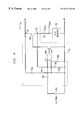
- FIG. 7 shows an alternative embodiment utilizing a single ended feedback loop and a common ground reference with the shunt regulator 700 to provide controllable AC modulation and DC termination characteristics to the telephone line.
- FIG. 7 only one terminal 703 of a sense resistor R sense between the series connection of the line modulator 702 and the shunt regulator 700 is sensed to provide a single ended feedback loop.
- the circuit of FIG. 7 is partially in series with the shunt regulator 700 yet retains a common ground reference with the shunt regulator 700 to the ring polarity signal RP.
- FIG. 8 shows the circuit of FIG. 7 in more detail.
- the line modulator 702 includes two single ended feedback loops.
- One feedback loop is from tip polarity (TP), and feeds back DC line voltage.
- the other feedback loop is from one terminal 703 of the sense resistor R SENSE and feeds back a voltage proportional to the line current.
- These feedback signals are used to set the DC termination and AC modulation characteristics.
- the line voltage feedback is divided down by resistor 700 g and 700 h and fed to the non-inverting terminal of op amp 700 a .
- Resistor 700 h is in parallel with capacitor 700 d to filter out AC voltage.
- the line current voltage feedback is divided down by resistor 700 f and resistor 700 e and fed to the inverting terminal of op amp 700 a .
- the sense resistor R sense is typically about 20 ohms, providing a gain of about thirty based on a telephone line impedance of about 600 ohms from the point of view of the tip polarity TP and ring polarity RP terminals.
- sense resistor R sense may be appropriate, e.g., 10 ohms, based on the particular application and/or the requirements of the central office.
- the shunt regulator 500 , sense resistor R sense , and line modulator/DC termination circuit 502 are in a series circuit between the tip polarity TP and ring polarity RP terminals. Accordingly, since the current is equal through the series circuit, those of ordinary skill in the art will appreciate that the order of the shunt regulator 500 , sense resistor R sense , and line modulator/DC termination circuit 502 may be placed in any order. For instance, the shunt regulator 500 as shown in FIG. 5 can be moved to a position between the tip polarity TP terminal and the line modulator/DC termination circuit 502 with the same results as described herein.
- the shunt regulator 700 provides power drawn from the telephone line to the line modulator/DC termination and feedback circuit 702 as well as to other modem and/or data processing circuitry necessary to provide a DC termination and AC modulation to the telephone line.
- An AC signal 700 k from a DSP or other modem circuitry powered by the shunt regulator 702 is AC coupled to the operational amplifier 700 a of the line modulator 702 through a capacitor 700 i.
- a bipolar pnp transistor 700 c placed in series with the shunt regulator 700 provides the AC modulation to the telephone line, and draws the prescribed amount of current from the telephone line, i.e., presents a DC termination to the telephone line.
- the output of the operational amplifier 700 a drives the base of bipolar npn transistor 700 b , the collector of which drives the base of transistor 700 c .
- the tip polarity TP to ring polarity RP DC voltage is divided down and coupled to the non-inverting terminal of operational amplifier 700 a through resistors 700 g and 700 h and capacitor 700 d.
- a portion of the DC termination of the line modulator/DC termination/feedback circuit 702 is established by the value of resistors 700 g , 700 h , 700 f and 700 e .
- Resistor 700 g is in series with resistor 700 h
- resistor 700 f is in series with resistor 700 e , both series connections of which are placed in parallel with the tip polarity signal TP and ring polarity signal RP of the telephone line.
- the circuit shown in FIGS. 7 and 8 senses the voltage V TP with respect to the ring polarity signal RP, and the current I TP of the tip polarity signal TP, and feeds back proportional voltages V 1 , V 2 determined by the voltage division of resistors 700 f and 700 e , and 700 g and 700 h , respectively, to the inverting and non-inverting inputs of operational amplifier 700 a , respectively.
- the AC component of the voltage V TP of the tip polarity signal TP is shunted to ground via capacitor 700 d.
- k 1 R 700 ⁇ h R 700 ⁇ e ⁇ R 700 ⁇ f + R 700 ⁇ e s ⁇ ⁇ C 700 ⁇ d ⁇ R 700 ⁇ g ⁇ R 700 ⁇ h + R 700 ⁇ g + R 700 ⁇ h ⁇ ⁇ Equation ⁇ ⁇ ( 1 ) ⁇ ⁇ is ⁇ ⁇ of ⁇ ⁇ the ⁇ ⁇ desired ⁇ ⁇ form ⁇ ⁇ sL effective + R effective ⁇ ⁇ where ⁇ : Eq .
- L effective C 700 ⁇ d ⁇ R 700 ⁇ g ⁇ R 700 ⁇ h ⁇ R sense R 700 ⁇ f + R 700 ⁇ e Eq . ⁇ ( 3 )
- R effective R sense ⁇ ( R 700 ⁇ g + R 700 ⁇ h ) R 700 ⁇ f + R 700 ⁇ e + V SR k 1 ⁇ I TP Eq . ⁇ ( 4 )
- V SR represents the voltage across the shunt regulator.
- k l I TP is to be considered when the component values for the circuit of FIGS. 7 and 8 are chosen.
- PSTN public switched telephone network
- the present invention provides a low noise DAA particularly useful for modems including DSPs and/or other line powered devices, and which includes DC termination and AC modulation characteristics which are software customizable for use in each of a plurality of countries.
- a common DAA can be manufactured and used in products in many countries, with the only difference between the products used in the various countries being in the software.
Abstract
Description


Claims (20)
Priority Applications (1)
| Application Number | Priority Date | Filing Date | Title |
|---|---|---|---|
| US09/055,991 US6731728B2 (en) | 1998-04-07 | 1998-04-07 | Low noise line powered DAA with differential feedback |
Applications Claiming Priority (1)
| Application Number | Priority Date | Filing Date | Title |
|---|---|---|---|
| US09/055,991 US6731728B2 (en) | 1998-04-07 | 1998-04-07 | Low noise line powered DAA with differential feedback |
Publications (2)
| Publication Number | Publication Date |
|---|---|
| US20030035534A1 US20030035534A1 (en) | 2003-02-20 |
| US6731728B2 true US6731728B2 (en) | 2004-05-04 |
Family
ID=22001432
Family Applications (1)
| Application Number | Title | Priority Date | Filing Date |
|---|---|---|---|
| US09/055,991 Expired - Fee Related US6731728B2 (en) | 1998-04-07 | 1998-04-07 | Low noise line powered DAA with differential feedback |
Country Status (1)
| Country | Link |
|---|---|
| US (1) | US6731728B2 (en) |
Cited By (11)
| Publication number | Priority date | Publication date | Assignee | Title |
|---|---|---|---|---|
| US6845156B1 (en) * | 2000-02-29 | 2005-01-18 | Agere Systems, Inc. | System for reducing distortion in a line powered modulator |
| US20050094802A1 (en) * | 2003-10-30 | 2005-05-05 | Tahir Ahmed | Direct access arrangement |
| US20070003054A1 (en) * | 2005-06-23 | 2007-01-04 | Agere Systems, Inc. | Continuous power transfer scheme for two-wire serial link |
| US20070003055A1 (en) * | 2005-06-23 | 2007-01-04 | Agere Systems, Inc. | Single-transformer digital isolation barrier |
| US7529053B1 (en) * | 2004-08-30 | 2009-05-05 | Marvell International Ltd. | TMR/GMR amplifier with input current compensation |
| US20110126265A1 (en) * | 2007-02-09 | 2011-05-26 | Fullerton Mark N | Security for codes running in non-trusted domains in a processor core |
| US8213489B2 (en) | 2005-06-23 | 2012-07-03 | Agere Systems Inc. | Serial protocol for agile sample rate switching |
| US20120314781A1 (en) * | 2011-06-10 | 2012-12-13 | Didier Boivin | Powerline Control Interface for Frequency and Amplitude Modulation Transmitter |
| US20130307506A1 (en) * | 2012-05-17 | 2013-11-21 | Rf Micro Devices, Inc. | Hybrid regulator with composite feedback |
| US20140198860A1 (en) * | 2013-01-17 | 2014-07-17 | Honda Motor Co., Ltd. | Power line carrier communication apparatus |
| US11393325B2 (en) * | 2018-03-23 | 2022-07-19 | Tyco Fire & Security Gmbh | Power control circuit |
Citations (20)
| Publication number | Priority date | Publication date | Assignee | Title |
|---|---|---|---|---|
| US4087647A (en) * | 1977-05-25 | 1978-05-02 | Bell Telephone Laboratories, Incorporated | Circuit for supplying direct current to telephone station sets |
| US4264785A (en) * | 1975-12-17 | 1981-04-28 | Sava Jacobson | Voltage regulator circuitry for a telephone answering device |
| US4302805A (en) * | 1977-12-27 | 1981-11-24 | Kyber Engineering, Inc. | Power supply utilizing a high frequency magnetic amplifier |
| US4530104A (en) * | 1983-01-12 | 1985-07-16 | Ncr Corporation | Circuit for reducing errors in a data receiver |
| US4578533A (en) * | 1980-11-03 | 1986-03-25 | Universal Data Systems, Inc. | Switchable line powered modem |
| US4622441A (en) * | 1984-06-21 | 1986-11-11 | Itt Corporation | Two-wire/four wire communication interface with noise rejection |
| US4796295A (en) * | 1985-10-07 | 1989-01-03 | Motorola, Inc. | Telephone circuits |
| US5086454A (en) * | 1989-11-17 | 1992-02-04 | Vocal Technologies, Ltd. | Direct connect modem deriving power from telephone line |
| US5451923A (en) * | 1992-10-05 | 1995-09-19 | Fisher Controls International, Inc. | Communication system and method |
| US5500894A (en) * | 1993-12-03 | 1996-03-19 | Silicon Systems, Inc. | Telephone line interface with AC and DC transconductance loops |
| US5528685A (en) * | 1994-07-08 | 1996-06-18 | At&T Corp. | Transformerless hybrid circuit |
| US5627890A (en) * | 1994-04-26 | 1997-05-06 | Motorola, Inc. | Telephone line interface circuit |
| US5742676A (en) * | 1995-09-29 | 1998-04-21 | U.S. Philips Corporation | Circuit for telephone set comprising a light-emitting diode power supply |
| US5774316A (en) * | 1996-08-26 | 1998-06-30 | Adtran, Inc. | Ground fault detector for line-powered telephone network |
| US5809068A (en) * | 1994-05-20 | 1998-09-15 | Multi-Tech Systems, Inc. | PCMCIA modem |
| US5946393A (en) * | 1997-02-10 | 1999-08-31 | Integration Associates, Inc. | Data access arrangement |
| US6091806A (en) * | 1997-10-16 | 2000-07-18 | International Business Machines Corporation | Data processing system having a programmable modem and method therefor |
| US6169762B1 (en) * | 1997-05-30 | 2001-01-02 | Lucent Technologies Inc. | Interface devices providing electrical isolation |
| US6205219B1 (en) * | 1998-02-24 | 2001-03-20 | Lucent Technologies, Inc. | Call related information reception using sigma/delta modulation |
| US6212226B1 (en) * | 1997-08-08 | 2001-04-03 | Lucent Technologies, Inc. | Supplemental power for battery operated modems |
-
1998
- 1998-04-07 US US09/055,991 patent/US6731728B2/en not_active Expired - Fee Related
Patent Citations (20)
| Publication number | Priority date | Publication date | Assignee | Title |
|---|---|---|---|---|
| US4264785A (en) * | 1975-12-17 | 1981-04-28 | Sava Jacobson | Voltage regulator circuitry for a telephone answering device |
| US4087647A (en) * | 1977-05-25 | 1978-05-02 | Bell Telephone Laboratories, Incorporated | Circuit for supplying direct current to telephone station sets |
| US4302805A (en) * | 1977-12-27 | 1981-11-24 | Kyber Engineering, Inc. | Power supply utilizing a high frequency magnetic amplifier |
| US4578533A (en) * | 1980-11-03 | 1986-03-25 | Universal Data Systems, Inc. | Switchable line powered modem |
| US4530104A (en) * | 1983-01-12 | 1985-07-16 | Ncr Corporation | Circuit for reducing errors in a data receiver |
| US4622441A (en) * | 1984-06-21 | 1986-11-11 | Itt Corporation | Two-wire/four wire communication interface with noise rejection |
| US4796295A (en) * | 1985-10-07 | 1989-01-03 | Motorola, Inc. | Telephone circuits |
| US5086454A (en) * | 1989-11-17 | 1992-02-04 | Vocal Technologies, Ltd. | Direct connect modem deriving power from telephone line |
| US5451923A (en) * | 1992-10-05 | 1995-09-19 | Fisher Controls International, Inc. | Communication system and method |
| US5500894A (en) * | 1993-12-03 | 1996-03-19 | Silicon Systems, Inc. | Telephone line interface with AC and DC transconductance loops |
| US5627890A (en) * | 1994-04-26 | 1997-05-06 | Motorola, Inc. | Telephone line interface circuit |
| US5809068A (en) * | 1994-05-20 | 1998-09-15 | Multi-Tech Systems, Inc. | PCMCIA modem |
| US5528685A (en) * | 1994-07-08 | 1996-06-18 | At&T Corp. | Transformerless hybrid circuit |
| US5742676A (en) * | 1995-09-29 | 1998-04-21 | U.S. Philips Corporation | Circuit for telephone set comprising a light-emitting diode power supply |
| US5774316A (en) * | 1996-08-26 | 1998-06-30 | Adtran, Inc. | Ground fault detector for line-powered telephone network |
| US5946393A (en) * | 1997-02-10 | 1999-08-31 | Integration Associates, Inc. | Data access arrangement |
| US6169762B1 (en) * | 1997-05-30 | 2001-01-02 | Lucent Technologies Inc. | Interface devices providing electrical isolation |
| US6212226B1 (en) * | 1997-08-08 | 2001-04-03 | Lucent Technologies, Inc. | Supplemental power for battery operated modems |
| US6091806A (en) * | 1997-10-16 | 2000-07-18 | International Business Machines Corporation | Data processing system having a programmable modem and method therefor |
| US6205219B1 (en) * | 1998-02-24 | 2001-03-20 | Lucent Technologies, Inc. | Call related information reception using sigma/delta modulation |
Cited By (23)
| Publication number | Priority date | Publication date | Assignee | Title |
|---|---|---|---|---|
| US6845156B1 (en) * | 2000-02-29 | 2005-01-18 | Agere Systems, Inc. | System for reducing distortion in a line powered modulator |
| US20050094802A1 (en) * | 2003-10-30 | 2005-05-05 | Tahir Ahmed | Direct access arrangement |
| US7751140B1 (en) | 2004-08-30 | 2010-07-06 | Marvell International Ltd. | TMR/GMR amplifier with input current compensation |
| US7881001B1 (en) | 2004-08-30 | 2011-02-01 | Marvell International Ltd. | Method and system for canceling feedback current in an amplifier system |
| US7529053B1 (en) * | 2004-08-30 | 2009-05-05 | Marvell International Ltd. | TMR/GMR amplifier with input current compensation |
| US7532427B1 (en) | 2004-08-30 | 2009-05-12 | Marvell International Ltd. | TMR/GMR amplifier with input current compensation |
| US7940921B2 (en) | 2005-06-23 | 2011-05-10 | Agere Systems Inc. | Continuous power transfer scheme for two-wire serial link |
| US8867182B2 (en) | 2005-06-23 | 2014-10-21 | Agere Systems Inc. | Signal-powered integrated circuit with ESD protection |
| US20100246695A1 (en) * | 2005-06-23 | 2010-09-30 | Agere Systems Inc. | Signal-powered integrated circuit with esd protection |
| US20070003055A1 (en) * | 2005-06-23 | 2007-01-04 | Agere Systems, Inc. | Single-transformer digital isolation barrier |
| US20070003054A1 (en) * | 2005-06-23 | 2007-01-04 | Agere Systems, Inc. | Continuous power transfer scheme for two-wire serial link |
| US7773733B2 (en) | 2005-06-23 | 2010-08-10 | Agere Systems Inc. | Single-transformer digital isolation barrier |
| US20110222682A1 (en) * | 2005-06-23 | 2011-09-15 | Agere Systems Inc. | Continuous Power Transfer Scheme for Two-Wire Serial Link |
| US8213489B2 (en) | 2005-06-23 | 2012-07-03 | Agere Systems Inc. | Serial protocol for agile sample rate switching |
| US8761236B2 (en) | 2005-06-23 | 2014-06-24 | Agere Systems Llc | Serial protocol for agile sample rate switching |
| US8442212B2 (en) | 2005-06-23 | 2013-05-14 | Agere Systems Llc | Continuous power transfer scheme for two-wire serial link |
| US20110126265A1 (en) * | 2007-02-09 | 2011-05-26 | Fullerton Mark N | Security for codes running in non-trusted domains in a processor core |
| US20120314781A1 (en) * | 2011-06-10 | 2012-12-13 | Didier Boivin | Powerline Control Interface for Frequency and Amplitude Modulation Transmitter |
| US20130307506A1 (en) * | 2012-05-17 | 2013-11-21 | Rf Micro Devices, Inc. | Hybrid regulator with composite feedback |
| US9235222B2 (en) * | 2012-05-17 | 2016-01-12 | Rf Micro Devices, Inc. | Hybrid regulator with composite feedback |
| US20140198860A1 (en) * | 2013-01-17 | 2014-07-17 | Honda Motor Co., Ltd. | Power line carrier communication apparatus |
| US9531438B2 (en) * | 2013-01-17 | 2016-12-27 | Rib Laboratory, Inc. | Power line carrier communication apparatus |
| US11393325B2 (en) * | 2018-03-23 | 2022-07-19 | Tyco Fire & Security Gmbh | Power control circuit |
Also Published As
| Publication number | Publication date |
|---|---|
| US20030035534A1 (en) | 2003-02-20 |
Similar Documents
| Publication | Publication Date | Title |
|---|---|---|
| US6731728B2 (en) | Low noise line powered DAA with differential feedback | |
| US6489755B1 (en) | Active ripple and noise filter for telecommunication equipment powering | |
| CA1155244A (en) | Apparatus for regulating current supplied to a telephone line | |
| EP0046588A1 (en) | Method of and circuit arrangement for supplying current to a two-wire telecommunications line | |
| EP1400014B1 (en) | Power amplifier (pa) with improved power regulation | |
| US6421430B1 (en) | Line powered DAA with single ended feedback | |
| EP0326968A1 (en) | A driving circuit having an electrical characteristics variable in response to its load resistance | |
| US6212226B1 (en) | Supplemental power for battery operated modems | |
| CA1177986A (en) | Balanced current multiplier circuit for a subscriber loop interface circuit | |
| EP0190110B1 (en) | Voltage convertor for telephone terminal equipment | |
| EP0087437B1 (en) | Telephone line circuit | |
| US4322586A (en) | Transformerless line interface circuit | |
| US20020070717A1 (en) | Apparatus and methods for boosting power supplied at a remote node | |
| US4156150A (en) | Circuit for regulating a DC voltage on which a large AC voltage is superimposed | |
| JPH0636539B2 (en) | DC control circuit for telephone interface circuit | |
| US4616302A (en) | Over-current sensing circuit for switching-type power supply | |
| JP3746809B2 (en) | Telephone line interface circuit | |
| JPS6292559A (en) | Telephone circuit | |
| US6661892B1 (en) | Method and apparatus for decreasing distortion in a line powered modulator circuit | |
| US5420919A (en) | Telephone line current modulator | |
| GB2183964A (en) | Telephone power supply | |
| US4263644A (en) | Current limiter for switched DC-to-DC converter | |
| US20070047729A1 (en) | Subscriber Line Interface Circuit (SLIC) Including A Transient Output Current Limit Circuit And Related Method | |
| US4485341A (en) | Current limiter circuit | |
| WO1982001267A1 (en) | Circuit for converting a non-live zero,current signal to a live zero dc output signal |
Legal Events
| Date | Code | Title | Description |
|---|---|---|---|
| AS | Assignment |
Owner name: LUCENT TECHNOLOGIES INC., NEW JERSEY Free format text: ASSIGNMENT OF ASSIGNORS INTEREST;ASSIGNORS:HOLLENBACH, KEITH EUGENE;LATURELL, DONALD RAYMOND;WITMER, STEVEN BROOKE;REEL/FRAME:009091/0180 Effective date: 19980406 |
|
| FPAY | Fee payment |
Year of fee payment: 4 |
|
| FPAY | Fee payment |
Year of fee payment: 8 |
|
| AS | Assignment |
Owner name: DEUTSCHE BANK AG NEW YORK BRANCH, AS COLLATERAL AG Free format text: PATENT SECURITY AGREEMENT;ASSIGNORS:LSI CORPORATION;AGERE SYSTEMS LLC;REEL/FRAME:032856/0031 Effective date: 20140506 |
|
| AS | Assignment |
Owner name: AVAGO TECHNOLOGIES GENERAL IP (SINGAPORE) PTE. LTD Free format text: ASSIGNMENT OF ASSIGNORS INTEREST;ASSIGNOR:AGERE SYSTEMS LLC;REEL/FRAME:035365/0634 Effective date: 20140804 |
|
| REMI | Maintenance fee reminder mailed | ||
| AS | Assignment |
Owner name: LSI CORPORATION, CALIFORNIA Free format text: TERMINATION AND RELEASE OF SECURITY INTEREST IN PATENT RIGHTS (RELEASES RF 032856-0031);ASSIGNOR:DEUTSCHE BANK AG NEW YORK BRANCH, AS COLLATERAL AGENT;REEL/FRAME:037684/0039 Effective date: 20160201 Owner name: AGERE SYSTEMS LLC, PENNSYLVANIA Free format text: TERMINATION AND RELEASE OF SECURITY INTEREST IN PATENT RIGHTS (RELEASES RF 032856-0031);ASSIGNOR:DEUTSCHE BANK AG NEW YORK BRANCH, AS COLLATERAL AGENT;REEL/FRAME:037684/0039 Effective date: 20160201 |
|
| LAPS | Lapse for failure to pay maintenance fees | ||
| STCH | Information on status: patent discontinuation |
Free format text: PATENT EXPIRED DUE TO NONPAYMENT OF MAINTENANCE FEES UNDER 37 CFR 1.362 |
|
| FP | Lapsed due to failure to pay maintenance fee |
Effective date: 20160504 |