US6745488B2 - Height-measuring column and method for regulating a height-measuring column - Google Patents
Height-measuring column and method for regulating a height-measuring column Download PDFInfo
- Publication number
- US6745488B2 US6745488B2 US10/314,805 US31480502A US6745488B2 US 6745488 B2 US6745488 B2 US 6745488B2 US 31480502 A US31480502 A US 31480502A US 6745488 B2 US6745488 B2 US 6745488B2
- Authority
- US
- United States
- Prior art keywords
- base
- height
- regulating
- measuring column
- supporting frame
- Prior art date
- Legal status (The legal status is an assumption and is not a legal conclusion. Google has not performed a legal analysis and makes no representation as to the accuracy of the status listed.)
- Expired - Lifetime
Links
Images


Classifications
-
- G—PHYSICS
- G01—MEASURING; TESTING
- G01B—MEASURING LENGTH, THICKNESS OR SIMILAR LINEAR DIMENSIONS; MEASURING ANGLES; MEASURING AREAS; MEASURING IRREGULARITIES OF SURFACES OR CONTOURS
- G01B5/00—Measuring arrangements characterised by the use of mechanical techniques
- G01B5/24—Measuring arrangements characterised by the use of mechanical techniques for measuring angles or tapers; for testing the alignment of axes
- G01B5/245—Measuring arrangements characterised by the use of mechanical techniques for measuring angles or tapers; for testing the alignment of axes for testing perpendicularity
-
- B—PERFORMING OPERATIONS; TRANSPORTING
- B23—MACHINE TOOLS; METAL-WORKING NOT OTHERWISE PROVIDED FOR
- B23Q—DETAILS, COMPONENTS, OR ACCESSORIES FOR MACHINE TOOLS, e.g. ARRANGEMENTS FOR COPYING OR CONTROLLING; MACHINE TOOLS IN GENERAL CHARACTERISED BY THE CONSTRUCTION OF PARTICULAR DETAILS OR COMPONENTS; COMBINATIONS OR ASSOCIATIONS OF METAL-WORKING MACHINES, NOT DIRECTED TO A PARTICULAR RESULT
- B23Q1/00—Members which are comprised in the general build-up of a form of machine, particularly relatively large fixed members
- B23Q1/0054—Means for adjusting the position of a machine tool with respect to its supporting surface
-
- G—PHYSICS
- G01—MEASURING; TESTING
- G01B—MEASURING LENGTH, THICKNESS OR SIMILAR LINEAR DIMENSIONS; MEASURING ANGLES; MEASURING AREAS; MEASURING IRREGULARITIES OF SURFACES OR CONTOURS
- G01B5/00—Measuring arrangements characterised by the use of mechanical techniques
- G01B5/0002—Arrangements for supporting, fixing or guiding the measuring instrument or the object to be measured
- G01B5/0007—Surface plates
-
- G—PHYSICS
- G01—MEASURING; TESTING
- G01B—MEASURING LENGTH, THICKNESS OR SIMILAR LINEAR DIMENSIONS; MEASURING ANGLES; MEASURING AREAS; MEASURING IRREGULARITIES OF SURFACES OR CONTOURS
- G01B5/00—Measuring arrangements characterised by the use of mechanical techniques
- G01B5/02—Measuring arrangements characterised by the use of mechanical techniques for measuring length, width or thickness
- G01B5/06—Measuring arrangements characterised by the use of mechanical techniques for measuring length, width or thickness for measuring thickness
- G01B5/061—Measuring arrangements characterised by the use of mechanical techniques for measuring length, width or thickness for measuring thickness height gauges
Definitions
- the present invention concerns a height-measuring column.
- the present invention concerns also the method for regulating a height-measuring column according to the invention.
- Height-measuring columns are measuring machines enabling the height of a point relative to a reference plane to be measured or the vertical distance between to measuring points to be calculated.
- the precision that is expected of such measuring machines is on the order of the micron.
- the main elements of a height-measuring column are generally:
- the base is the element through which the height-measuring column is in contact with the floor, generally a plane surface that can serve as reference to the measuring reference frame.
- the base also ensures the stability of the height-measuring column.
- the supporting frame is essentially perpendicular to the base's seat and generally has on its length rails guiding the displacement of the carriage. It thus determines the measuring axis, essentially perpendicular to the plane of the base's seat of the height-measuring column.
- the carriage is the mobile element of the height-measuring column. It moves on the supporting frame along the measuring axis, generally on perfectly rectilinear rails guiding its movement and ensuring that it is fastened.
- the probe tip is mounted on the carriage and is designed for being brought into contact with the piece to be measured.
- the contact point is determined either visually, or automatically, for example by a mechanism stopping the carriage's movement as soon as a pressure exceeding a predetermined threshold is exerted on the probe tip. The height of the contact point can then be measured.
- the measuring system comprises elements for example inductive, capacitive or opto-electronic integrated to the supporting frame, enabling the carriage's position along the measuring axis to be determined accurately.
- the measuring system is generally equipped with a system for displaying the measure and/or with an information processing software.
- the driving mechanism controls the displacement of the carriage on the supporting frame. It is generally an electric motor driving a belt or cable fastened to the carriage and guided by a pulley at the top and sometimes at the bottom of the supporting frame.
- the driving mechanism has mechanical and/or electronic controls enabling an accurate positioning of the carriage and therefore of the probe tip.
- a height-measuring column can also be used for perpendicular measuring.
- the probe tip can in this case be replaced by a comparator that is displaced flush along a surface of the piece to be measured, detecting any variation in the distance between the surface to be measured and the displacement axis of the comparator.
- the perpendicularity between the measuring axis and the reference surface becomes the essential factor of the measuring accuracy. This perpendicularity must consequently be perfectly regulated.
- An electronic correction circuit is superfluous, since the information supplied by the comparator is binary.
- this aim is achieved by means of a measuring column having the characteristics of the first independent claim. This aim is further achieved by means of a regulating method indicated in the second independent claim.
- this aim is achieved by means of a height-measuring column whose perpendicularity between the supporting frame and the base can be regulated, thus allowing by extension the perpendicularity of the measuring axis relative to the reference surface to be regulated.
- the regulating of the perpendicularity between the supporting frame and the base of the height-measuring column makes it possible to compensate the inaccuracies in the parallelism or in the regularity of the contact surfaces between the different elements of the height-measuring column, in particular between the supporting frame and the base.
- the manufacture of these pieces is simplified and the costs are reduced.
- FIG. 1 shows a simplified view of a height-measuring column.
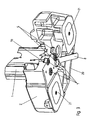
- FIG. 2 shows a cross section of the base and of the seat of the supporting frame of a height-measuring column according to the invention.
- FIG. 3 shows a view in perspective of the base and of the seat of the supporting frame of a height-measuring column according to the invention.
- the preferred embodiment of the invention is a height-measuring column comprising a supporting frame 1 fastened on a base 3 perpendicular to the seat of this base 2 , a carriage 4 moving on rails 10 along the supporting frame 1 thus defining the measuring axis.
- a probe tip 40 or a comparator (not represented) will be fastened on the carriage 4 .
- the height-measuring column according to the preferred embodiment of the invention also comprises a measuring system in order to determine exactly the position of the carriage on the supporting frame and, by extension, to determine the coordinates on the position measuring axis, for example of the probe tip or of the comparator fastened to the carriage.
- the height-measuring column further comprises a driving mechanism controlling the movements of the carriage 4 along the supporting frame 1 .
- the height-measuring column is designed to function on a plane reference surface 3 that can serve as zero point of the measuring axis, for example a marble or granite table.
- the supporting frame 1 of the height-measuring column is fastened to the base 2 by means of fastening elements.
- the function of the fastening elements is to ensure that the supporting frame 1 is held on the base 2 and that any mechanical play between these elements after assembly is avoided.
- these fastening elements are for example three fastening screws 7 .
- the fastening screws 7 are inserted in the holes provided for this purpose under the base 2 of the height-measuring column, then screwed in the holes threaded at the bottom of the supporting frame 1 located opposite the holes of the base 2 when the base 2 and the supporting frame 1 are assembled.
- the fastening screws 7 are preferably fillister-head screws provided with washers 70 in order to spread the force exerted around the head on the base 2 during screwing.
- the washers 70 will preferably be of the self-blocking type and can be secured by a drop of glue or of a screw locking product.
- the regulating of the perpendicularity is performed by means of regulating elements.
- These regulating elements are for example two regulating screws 5 parallel to the fastening screws 7 .
- the regulating screws 5 are screwed in the threaded holes provided for this purpose in the base 2 . Their extremity rests against the lower surface of the supporting frame 1 , thus exerting on the supporting frame a force in the opposite direction of that of the force exerted by the fastening screws 7 .
- brass pellets 6 with parallel sides are preferably intercalated between the regulating screws 5 and the base of the supporting frame 1 .
- Regulating screws are preferably prestressed by the tightening of the fastening screws 7 .
- the three fastening screws 7 are first tightened at 60-70% of the blocking force.
- the two regulating screws are then screwed until a certain force is exerted against the lower surface of the supporting frame 1 .
- the fastening screws 7 are finally blocked and then possibly further secured against unscrewing, for example by adjunction of a drop of glue or of a screw locking product around the screw's head.
- the three fastening screws 7 are placed along an equilateral triangle having a base and a height more or less equal to three times the diameter of the head of said fastening screws 7 .
- the two regulating screws 5 are preferably placed on each side of the fastening screw situated at the top of said equilateral triangle, along an axis parallel to the base of said equilateral triangle, the spacing between the regulating screws 5 being more or less equal to the spacing between the two fastening screws forming the base of said equilateral triangle.
- the screwing of a regulating screw and unscrewing of the opposite regulating screw allows the position of the supporting frame 1 to be regulated relative to the base 2 in a plane parallel to the plane formed by the two regulating screws 5 , i.e., in the represented embodiment, in a plane parallel to the plane of the section of FIG. 2 .
- the screwing or unscrewing of the two regulating screws 5 allows the position of the supporting frame 1 to be regulated relative to the base 2 in a plane perpendicular to the plane formed by the two regulating screws 5 , i.e., in the represented embodiment, in a plane perpendicular to the plane of the section of FIG. 2 .
- the perpendicularity between the measuring axis connected to the supporting frame 1 and the reference surface 3 must be adjusted.
- the height-measuring column is placed vertically 2 on the reference surface 3 .
- the screwing of each regulating screw 5 is then adjusted alternatively until the sought precision has been achieved.
- the regulating screws 5 are preferably hexagon head screws that can be thus regulated by means of an adapted wrench 8 slid under an aperture 20 at the bottom of the base 2 .
- a variant embodiment would be to regulate the perpendicularity on a reference surface in which a hole allows access to the regulating screws from below. This variant embodiment is however less comfortable for the operator in charge of regulating the perpendicularity.
- the temporal stability of the perpendicularity adjustment of a height-measuring column according to the invention is ensured by the fact that the regulating screws 5 are prestressed.
- the regulating screws 5 being strongly compressed, their material is constantly at the limits of its elasticity, thus reducing the amplitude of a possible subsequent compression.
- the adjustment's temporal stability is also improved by spreading the fastening elements and the regulating elements on a square surface whose side is more or less equal to the length of a fastening element framed by two regulating elements. The limitation of this surface ensures a very short closing of the force loop, thus limiting the material's fatigue that could for example result in constant torque moments that are too great.
- the supporting frame is fastened to the base with three fastening screws.
- the one skilled in the art will easily understand that the function of the fastening screws 7 according to the invention is to fasten the two elements together rigidly. It is conceivable to realize this fastening by means of other fastening elements, such as for example hooks or notches.
- the lower side of the base 2 contains cavities 21 in which a stream of compressed air with a non-singular direction circulates.
- the air is drawn in from the ground, thus strongly pinning the measuring column onto the reference surface 3 and ensuring a good stability. This prevents the column from moving or even overturning during adjustment.
- the air stream is reversed, thus slightly lifting the height-measuring column and making it easier to displace it.
Abstract
Description
Claims (24)
Applications Claiming Priority (3)
| Application Number | Priority Date | Filing Date | Title |
|---|---|---|---|
| EPEP01811219.3 | 2001-12-12 | ||
| EP01811219A EP1319925B1 (en) | 2001-12-12 | 2001-12-12 | Height gauge |
| EP01811219 | 2001-12-12 |
Publications (2)
| Publication Number | Publication Date |
|---|---|
| US20030106235A1 US20030106235A1 (en) | 2003-06-12 |
| US6745488B2 true US6745488B2 (en) | 2004-06-08 |
Family
ID=8184313
Family Applications (1)
| Application Number | Title | Priority Date | Filing Date |
|---|---|---|---|
| US10/314,805 Expired - Lifetime US6745488B2 (en) | 2001-12-12 | 2002-12-09 | Height-measuring column and method for regulating a height-measuring column |
Country Status (6)
| Country | Link |
|---|---|
| US (1) | US6745488B2 (en) |
| EP (1) | EP1319925B1 (en) |
| JP (1) | JP3818960B2 (en) |
| CN (1) | CN100374812C (en) |
| DE (1) | DE60131182T2 (en) |
| HK (1) | HK1054785A1 (en) |
Cited By (2)
| Publication number | Priority date | Publication date | Assignee | Title |
|---|---|---|---|---|
| US7263786B1 (en) * | 2006-04-19 | 2007-09-04 | Tesa Sa | Height gauge |
| US20110167658A1 (en) * | 2010-01-12 | 2011-07-14 | Biospace Co., Ltd. | Automatic anthropometer |
Families Citing this family (6)
| Publication number | Priority date | Publication date | Assignee | Title |
|---|---|---|---|---|
| EP1241436B1 (en) * | 2001-03-14 | 2014-11-19 | Tesa Sa | Coordinate measuring machine and method for introducing a command to change the measurement mode in this machine |
| US9933248B2 (en) * | 2016-07-20 | 2018-04-03 | Tesa Sa | Height gauge |
| CN107860299A (en) * | 2017-11-24 | 2018-03-30 | 张化机(苏州)重装有限公司 | Cradle cylinder body roundness measurement device |
| CN111678409B (en) * | 2020-06-16 | 2022-03-15 | 玉溪中烟种子有限责任公司 | Plant height acquisition device, method and system |
| CN112284204B (en) * | 2020-10-13 | 2023-03-31 | 哈电集团(秦皇岛)重型装备有限公司 | Device and method for measuring position degree of screw polished rod axis |
| CN113680683B (en) * | 2021-08-22 | 2022-03-11 | 余姚市新丰轴承有限公司 | Vehicle head bowl bearing assembly inclination height detection equipment and detection method thereof |
Citations (6)
| Publication number | Priority date | Publication date | Assignee | Title |
|---|---|---|---|---|
| CH236041A (en) | 1943-05-01 | 1945-01-15 | Waelle Jakob | Device for converting a slide gauge into a height marker. |
| US3753295A (en) | 1971-07-22 | 1973-08-21 | H Hecklinger | Height gauge and auxiliary attachments therefor |
| FR2201756A5 (en) | 1972-09-29 | 1974-04-26 | Balea Georges | |
| US4667922A (en) | 1985-11-08 | 1987-05-26 | The United States Of America As Represented By The United States Department Of Energy | Support assembly having three dimension position adjustment capabilities |
| US5373645A (en) | 1992-07-16 | 1994-12-20 | Tesa S.A. | Apparatus for the measurement of linear values |
| US6446351B1 (en) * | 1999-04-13 | 2002-09-10 | Mitutoyo Corporation | Linear measuring machine |
-
2001
- 2001-12-12 DE DE60131182T patent/DE60131182T2/en not_active Expired - Lifetime
- 2001-12-12 EP EP01811219A patent/EP1319925B1/en not_active Expired - Lifetime
-
2002
- 2002-12-09 US US10/314,805 patent/US6745488B2/en not_active Expired - Lifetime
- 2002-12-11 CN CNB021399948A patent/CN100374812C/en not_active Expired - Fee Related
- 2002-12-12 JP JP2002360729A patent/JP3818960B2/en not_active Expired - Fee Related
-
2003
- 2003-09-26 HK HK03106965A patent/HK1054785A1/en not_active IP Right Cessation
Patent Citations (6)
| Publication number | Priority date | Publication date | Assignee | Title |
|---|---|---|---|---|
| CH236041A (en) | 1943-05-01 | 1945-01-15 | Waelle Jakob | Device for converting a slide gauge into a height marker. |
| US3753295A (en) | 1971-07-22 | 1973-08-21 | H Hecklinger | Height gauge and auxiliary attachments therefor |
| FR2201756A5 (en) | 1972-09-29 | 1974-04-26 | Balea Georges | |
| US4667922A (en) | 1985-11-08 | 1987-05-26 | The United States Of America As Represented By The United States Department Of Energy | Support assembly having three dimension position adjustment capabilities |
| US5373645A (en) | 1992-07-16 | 1994-12-20 | Tesa S.A. | Apparatus for the measurement of linear values |
| US6446351B1 (en) * | 1999-04-13 | 2002-09-10 | Mitutoyo Corporation | Linear measuring machine |
Cited By (3)
| Publication number | Priority date | Publication date | Assignee | Title |
|---|---|---|---|---|
| US7263786B1 (en) * | 2006-04-19 | 2007-09-04 | Tesa Sa | Height gauge |
| US20110167658A1 (en) * | 2010-01-12 | 2011-07-14 | Biospace Co., Ltd. | Automatic anthropometer |
| US8322043B2 (en) * | 2010-01-12 | 2012-12-04 | Biospace Co., Ltd. | Automatic anthropometer |
Also Published As
| Publication number | Publication date |
|---|---|
| JP2003194505A (en) | 2003-07-09 |
| EP1319925A1 (en) | 2003-06-18 |
| DE60131182D1 (en) | 2007-12-13 |
| HK1054785A1 (en) | 2003-12-12 |
| CN1430041A (en) | 2003-07-16 |
| JP3818960B2 (en) | 2006-09-06 |
| CN100374812C (en) | 2008-03-12 |
| DE60131182T2 (en) | 2008-08-14 |
| EP1319925B1 (en) | 2007-10-31 |
| US20030106235A1 (en) | 2003-06-12 |
Similar Documents
| Publication | Publication Date | Title |
|---|---|---|
| JP5215866B2 (en) | Device for determining measurable variables for a measurement object | |
| KR102199515B1 (en) | A fixing jig for drilling | |
| US6745488B2 (en) | Height-measuring column and method for regulating a height-measuring column | |
| CN109341486B (en) | Systematic measuring device and measuring method for inner ring and outer ring of channel bearing | |
| US4630381A (en) | Coordinate measuring instrument | |
| US6839976B2 (en) | Stand for manufacturing bicycles | |
| US9494400B1 (en) | Linear measuring system | |
| US9895781B2 (en) | Apparatus for mounting an accessory to a coordinate positioning apparatus | |
| JP7274998B2 (en) | Grinding equipment | |
| US2397492A (en) | Machinist's gauge | |
| US6408530B1 (en) | Coordinate measuring instrument or machining equipment | |
| US3975828A (en) | Adjustable master setting gauge | |
| CN208476127U (en) | A kind of stabilization three coordinate measuring machine | |
| KR20210001604U (en) | Marking gauges of strings with precision ruler | |
| CN217764942U (en) | Measuring and positioning device for gear shaft part | |
| CN116753808B (en) | Device, method and correction method for measuring special-shaped groove of contact type sliding rail | |
| CN210588436U (en) | Ball arm instrument special fixture for numerical control machine tool | |
| US6498047B2 (en) | Apparatus and method for measuring wafer clamping tension | |
| CN219416550U (en) | Calibrating device for tension measuring instrument | |
| US6449867B1 (en) | Apparatus and method for measuring a dimension of a workpiece | |
| CN213515965U (en) | High stable platform scale | |
| CN214621224U (en) | High-precision automatic level ruler calibrating device | |
| KR102505644B1 (en) | Thickness gauge | |
| CN214237187U (en) | Novel precision positioning device | |
| CN106526509B (en) | Detection distance control mechanism for magnetic flux density detection |
Legal Events
| Date | Code | Title | Description |
|---|---|---|---|
| AS | Assignment |
Owner name: BROWN & SHARPE TESA SA, SWITZERLAND Free format text: ASSIGNMENT OF ASSIGNORS INTEREST;ASSIGNORS:JORDIL, PASCAL;ZANIER, ADRIANO;REEL/FRAME:013560/0698 Effective date: 20020912 |
|
| AS | Assignment |
Owner name: TESA SA, SWITZERLAND Free format text: CHANGE OF NAME;ASSIGNOR:BROWN & SHARPE TESA SA;REEL/FRAME:014579/0109 Effective date: 20030108 |
|
| FEPP | Fee payment procedure |
Free format text: PAYOR NUMBER ASSIGNED (ORIGINAL EVENT CODE: ASPN); ENTITY STATUS OF PATENT OWNER: LARGE ENTITY |
|
| STCF | Information on status: patent grant |
Free format text: PATENTED CASE |
|
| FPAY | Fee payment |
Year of fee payment: 4 |
|
| FEPP | Fee payment procedure |
Free format text: PAYER NUMBER DE-ASSIGNED (ORIGINAL EVENT CODE: RMPN); ENTITY STATUS OF PATENT OWNER: LARGE ENTITY Free format text: PAYOR NUMBER ASSIGNED (ORIGINAL EVENT CODE: ASPN); ENTITY STATUS OF PATENT OWNER: LARGE ENTITY |
|
| FPAY | Fee payment |
Year of fee payment: 8 |
|
| FPAY | Fee payment |
Year of fee payment: 12 |