US6764220B2 - Assembly for use in connecting optical fibers - Google Patents

Assembly for use in connecting optical fibers Download PDF

Info

Publication number
US6764220B2
US6764220B2 US10/162,766 US16276602A US6764220B2 US 6764220 B2 US6764220 B2 US 6764220B2 US 16276602 A US16276602 A US 16276602A US 6764220 B2 US6764220 B2 US 6764220B2
Authority
US
United States
Prior art keywords
optical fibres
guide
assembly
outlet ports
fibres
Prior art date
Legal status (The legal status is an assumption and is not a legal conclusion. Google has not performed a legal analysis and makes no representation as to the accuracy of the status listed.)
Expired - Lifetime, expires
Application number
US10/162,766
Other versions
US20020186953A1 (en
Inventor
Ian James Griffiths
John Kerry
Malcolm Owen Jones
Current Assignee (The listed assignees may be inaccurate. Google has not performed a legal analysis and makes no representation or warranty as to the accuracy of the list.)
Prysmian Cables and Systems Ltd
Original Assignee
Prysmian Cables and Systems Ltd
Priority date (The priority date is an assumption and is not a legal conclusion. Google has not performed a legal analysis and makes no representation as to the accuracy of the date listed.)
Filing date
Publication date
Application filed by Prysmian Cables and Systems Ltd filed Critical Prysmian Cables and Systems Ltd
Assigned to PIRELLI GENERAL PLC reassignment PIRELLI GENERAL PLC ASSIGNMENT OF ASSIGNORS INTEREST (SEE DOCUMENT FOR DETAILS). Assignors: GRIFFITHS, IAN JAMES, JONES, MALCOLM OWEN, KERRY, JOHN
Publication of US20020186953A1 publication Critical patent/US20020186953A1/en
Application granted granted Critical
Publication of US6764220B2 publication Critical patent/US6764220B2/en
Assigned to PRYSMIAN CABLES & SYSTEMS LIMITED reassignment PRYSMIAN CABLES & SYSTEMS LIMITED CHANGE OF NAME (SEE DOCUMENT FOR DETAILS). Assignors: PIRELLI GENERAL PLC
Adjusted expiration legal-status Critical
Expired - Lifetime legal-status Critical Current

Links

Images

Classifications

    • GPHYSICS
    • G02OPTICS
    • G02BOPTICAL ELEMENTS, SYSTEMS OR APPARATUS
    • G02B6/00Light guides; Structural details of arrangements comprising light guides and other optical elements, e.g. couplings
    • G02B6/24Coupling light guides
    • G02B6/36Mechanical coupling means
    • G02B6/38Mechanical coupling means having fibre to fibre mating means
    • G02B6/3807Dismountable connectors, i.e. comprising plugs
    • G02B6/3873Connectors using guide surfaces for aligning ferrule ends, e.g. tubes, sleeves, V-grooves, rods, pins, balls
    • G02B6/3874Connectors using guide surfaces for aligning ferrule ends, e.g. tubes, sleeves, V-grooves, rods, pins, balls using tubes, sleeves to align ferrules
    • G02B6/3878Connectors using guide surfaces for aligning ferrule ends, e.g. tubes, sleeves, V-grooves, rods, pins, balls using tubes, sleeves to align ferrules comprising a plurality of ferrules, branching and break-out means
    • GPHYSICS
    • G02OPTICS
    • G02BOPTICAL ELEMENTS, SYSTEMS OR APPARATUS
    • G02B6/00Light guides; Structural details of arrangements comprising light guides and other optical elements, e.g. couplings
    • G02B6/44Mechanical structures for providing tensile strength and external protection for fibres, e.g. optical transmission cables
    • G02B6/4439Auxiliary devices
    • G02B6/4471Terminating devices ; Cable clamps
    • G02B6/4472Manifolds

Definitions

  • the present invention provides an assembly for use in connecting optical fibres.
  • the invention is particularly, but riot exclusively, applicable to the management and routing of optical fibres at joints therefor.
  • joints are provided where it is desired to distribute optical fibres to customers.
  • optical fibres leading from a main network may be connected to fibres leading to individual customer locations.
  • fibres from the main network will be described as being supplied along a primary cable and fibres leading to customer locations will be described as secondary fibres.
  • such joints can be provided to connect optical fibres from two primary cables thereby increasing the total length of cable.
  • Such joints are usually provided under ground and may be accessed via a man-hole to enable connections and routing to be made.
  • Optical fibres may be provided in fibre units, or bundles, which may comprise a number of fibres extending along a tube.
  • optical fibre bundles enter a joint along a primary cable and are separated.
  • eight or twelve fibres are provided in a fibre unit, or bundle, and these optical fibres are managed and routed to housings, or splice trays, where they may be connected to secondary optical fibres leading to individual customers.
  • housings, or splice trays An example of these housings or splice trays is disclosed in the applicant's earlier application, EP-A-981775.
  • Each housing comprises one port into which fibres may be routed from a primary cable and a second port into which secondary fibres may be routed from customer locations.
  • the housings can be used to connect fibres from two primary cables.
  • the present invention is particularly but not exclusively applicable to the routing of fibres from a primary cable to the housings or splice trays.
  • FIG. 9 A fibre bundle 100 containing, for example eight fibres, is separated from a primary cable (not shown) and inserted into the guide device 102 at inlet port 103 .
  • Optical fibres 104 extend out of the tube of the fibre bundle and may be separated into single or individual groups of optical fibres 106 which are distributed out of the guide device 102 at outlet ports 107 and into an associated housing 108 in a stack 110 of housings where connections to other optical fibres are made.
  • a primary cable contains more than one optical fibre bundle, for example, twelve bundles that may each contain eight optical fibres, making ninety-six optical fibres in total.
  • two fibres were needed to allow communication at a customer location—a first optical fibre transmits light and a second optical fibre receives light. Therefore, the exemplary primary cable having twelve fibre bundles with eight fibres in each may be connected to a joint for distribution to a maximum of forty-eight customer locations.
  • Each customer is allocated at least one housing from which two secondary fibres lead to the customer location.
  • eight fibres 104 of an optical fibre bundle 100 are separated into groups of two fibres 106 , each group leading into a housing. Therefore, twelve of the prior art guide devices shown in FIG. 9 are provided for routing the optical fibres to the respective housings, each device being associated with four housings and each fibre bundle leading to a guide device.
  • optical fibre bundles are often provided with twelve optical fibres and both single and two fibre circuits may be required.
  • the present invention provides an assembly for use in connecting optical fibres, the assembly comprising a plurality of housings for housing connections between optical fibres and a guide arrangement for guiding optical fibres into said housings, said guide arrangement comprising a plurality of guide devices mounted side-by-side, each guide device having at least one inlet port for the passage of optical fibres into the guide arrangement, at least one outlet port associated with a said housing for guiding optical fibres into the associated housing, at least one further inlet port for receiving optical fibres from another one of said guide devices when positioned adjacent said guide device on one side thereof and at least one further outlet port for guiding optical fibres to another one of said guide devices when positioned adjacent said guide device on another side thereof, said guide arrangement comprising at least two guide devices.
  • the or each inlet port may have a substantially cylindrical portion to correspond with the shape of a tubular member containing optical fibres so that a push-fit connection can be achieved by such a tubular member in the inlet port.
  • Each guide device may provide a plurality of fixed tracks extending from said at least one further inlet port to said at least one outlet port and to said at least one further outlet port for guiding optical fibres from the or each further inlet port to said at least one outlet port and to said at least one further outlet port.
  • Said fixed tracks may be channels and have a bend radius not less than a predetermined distance for reducing signal attenuation in optical fibres disposed therein.
  • the further outlet ports of one of said guide devices may be adjacent the further inlet ports of another of said guide devices for guiding optical fibres between said one and said other guide devices.
  • Fixed tracks may provide tracks which extend from the or each inlet port of one of said devices to the outlet ports of another of said guide devices and said tracks have a bend radius not less than a predetermined distance for reducing signal attenuation in optical fibres disposed in the tracks.
  • FIG. 1 is a schematic view of an assembly for use in connecting optical fibres
  • FIG. 2 is a diagram showing fibre routing in a guide device and housing
  • FIG. 3 is a detailed plan view of the guide device
  • FIG. 4 is a detailed elevational view of the guide device
  • FIG. 5 is a detailed plan view of one of the guide devices guiding optical fibres from an eight fibre bundle on a two fibre per housing basis;
  • FIG. 6 is a detailed plan view of two of the guide devices guiding optical fibres from a twelve fibre bundle on a two fibre per housing basis;
  • FIG. 7 is a detailed plan view of two of the guide devices guiding optical fibres from an eight fibre bundle on a one fibre per housing basis;
  • FIG. 8 is a detailed plan view of one of the guide devices guiding optical fibres from a twelve fibre bundle on a one fibre per housing basis;
  • FIG. 9 is a schematic view of a prior art assembly for use in connecting optical fibres.
  • an assembly 10 for connecting optical fibres, the assembly 10 comprising a plurality of housings 12 for housing connections between optical fibres and a guide arrangement 13 for guiding optical fibres into said housings 12 .
  • the guide arrangement 13 comprises two guide devices 14 mounted side-by-side.
  • the housings 12 may be provided in units of four housings, each unit being supplied with a guide device 14 .
  • the housings 12 and the two guide devices 14 are in a stacked arrangement with the guide devices being adjacent to one another and fitted in the assembly relative to the housings.
  • the stack may comprise only two guide devices fitted relative to the housings and as demand increases further housings and guide devices can be added to the stack.
  • FIG. 2 shows the routing of an optical fibre 16 of an optical fibre bundle 18 that has been separated from a primary cable and introduced to a guide device 14 .
  • Fibre 16 is guided through guide device 14 and into housing 12 where it is routed into position for splicing with fibre 20 .
  • Fibre 20 may be a secondary fibre leading to an individual customer location or may be a fibre of a fibre bundle from another primary cable. Fibres 16 and 20 are spliced together at position X in housing 12 .
  • the guide device 14 is shown in more detail and provides an inlet port 22 into which an end portion 23 ′ of a tubular member 23 (FIG. 5) containing a fibre bundle 18 can be inserted through a substantially circular aperture for the passage of optical fibres into the guide arrangement.
  • Inlet port 22 has a substantially cylindrical portion to correspond with the shape of the end portion 23 ′ of the tubular member 23 so that it can be push-fitted, or plugged, into the inlet port 22 . Only a central section of the end portion 23 ′ shows through a longitudinal slit in the face of the guide device 14 .
  • Inlet port 22 also comprises a flanged portion against which the end portion 23 ′ of the tubular member 23 abuts when push-fitted into the inlet port 22 to limit travel of the tubular member into the inlet port 22 .
  • the flanged portion provides a slit through which optical fibres 16 extend from the tubular member 23 and into the guide device 14 along portion 24 .
  • the illustrated guide device is provided with only one inlet port 22 , more than one such port may be provided to permit insertion of a fibre bundle 18 from more than one direction.
  • Outlet ports 26 are provided and each are associated with a respective housing 12 (not shown in FIGS. 3 and 4) for guiding optical fibres into the respective housing 12 .
  • the guide device 14 comprises further ports including outlet ports 28 and inlet ports 30 .
  • Further outlet ports 28 are provided for guiding optical fibres to an adjacent like guide device and further inlet ports 30 are provided for receiving optical fibres from an adjacent like guide device.
  • Respective further outlet and inlet ports 28 , 30 of adjacent guide devices are arranged to be aligned so that optical fibres can readily be guided from the further outlet ports 28 of one guide device to the further inlet ports 30 of the adjacent guide device, as is shown in FIGS. 6 to 8 described below.
  • the guide device 14 comprises a plurality of fixed tracks 32 ′ and 32 ′′.
  • a first plurality of fixed tracks 32 ′ extend from inlet port 22 to outlet ports 26 and to further outlet ports 28 for guiding optical fibres from the inlet port 22 to the outlet ports 26 and to the further outlet ports 28 .
  • a second plurality of fixed tracks 32 ′′ extend from further inlet ports 30 to outlet ports 26 and to further outlet ports 28 for guiding optical fibres from the further inlet port 30 to the outlet ports 26 and to the further outlet ports 28 .
  • fixed tracks 32 ′ and fixed tracks 32 ′′ may be coextensive and over such a portion can guide fibres from either or both of the inlet port 22 and the further inlet ports 30 .
  • the fixed tracks illustrated are in the form of channels so that fibres can readily be pressed laterally into the fixed tracks.
  • the fixed tracks may alternatively be bores through which optical fibres may be threaded.
  • the illustrated channels have retaining tabs 34 for retaining optical fibres when introduced to the channels.
  • a transparent cover (not shown) may also be fitted to the guide device for preventing dislodgement of the optical fibres once they are pressed into the channels. The cover is engageable with apertures 36 and barbs 38 on the guide device 14 .
  • the fixed tracks 32 ′, 32 ′′ have a radius of curvature, or bend radius, no less than a predetermined distance for reducing signal attenuation of optical fibres disposed in the fixed tracks 32 ′, 32 ′′.
  • the minimum radius of curvature is preferably 30 mm.
  • the fixed tracks leading to the further outlet ports 28 of one guide device are aligned with and of a similar radius of curvature to the fixed tracks leading from the further inlet ports 30 of an adjacent like guide device. In this way, fixed tracks 32 ′, 32 ′′ provide tracks which extend from the or each inlet port 22 of one guide device 14 to the outlet ports 26 of another guide device 14 and said tracks have a minimum bend radius for reducing signal attenuation in optical fibres disposed therein.
  • the guide device 14 is fitted to the housings by use of spigots 40 and barbs 42 which engage with optical fibre inlet ports (not shown) and recesses (not shown), respectively, provided in the housings 12 .
  • any suitable means of fitting the guide device 12 to the housings 14 may be provided as required.
  • FIGS. 5 to 8 show exemplary routing arrangements of optical fibres using one or more guide devices 14 . After passing through the outlet ports 26 of the illustrated guide devices 14 , the optical fibres 16 are introduced into associated housings (not shown).
  • FIG. 5 shows a guide device 14 with an optical fibre bundle 18 having eight fibres 16 guided on a two fibre per housing basis.
  • the eight fibres are introduced to the guide device at the inlet port 22 .
  • Each group of two fibres follows a fixed track 32 ′ to a respective outlet port 26 .
  • the further ports 28 , 30 and fixed tracks 32 ′′ are not used in this arrangement, they are available for guiding fibres to and receiving fibres from adjacent guide devices as required.
  • FIG. 6 shows how fibre bundles 18 having twelve fibres 16 are routed on a two fibre per housing basis.
  • Two fibre bundles 18 with twelve fibres in each are introduced at the inlet ports 22 of two of three guide devices 14 .
  • the fibres in the two bundles are separated into twelve groups of two fibres, each group being guided along a respective fixed track 32 ′, 32 ′′ to an outlet port 26 .
  • some fibres 16 introduced at the inlet port 22 of a first guide device 14 are guided along fixed tracks 32 ′ to a further outlet port 28 of the first guide device 14 and to the further inlet port 30 of an adjacent guide device 14 from which they are guided to an outlet port 26 of the adjacent guide device 14 along fixed tracks 32 ′′.
  • these optical fibres 16 are guided along tracks (including fixed tracks 32 ′ and fixed tracks 32 ′′) which extend from the inlet port 22 of one device 14 to the outlet ports 26 of another of the guide devices 14 and these tracks have a minimum bend radius for preventing signal attenuation of the optical fibres disposed therein.
  • FIGS. 7 and 8 show, respectively, how optical fibre bundles 18 having eight and twelve fibres are routed on a one fibre per housing basis.
  • fibres introduced into a first guide device 14 are guided to outlet ports 26 of both the first and an adjacent guide device 14 .
  • optical fibres 16 are also guided to the outlet ports 26 of a third guide device 14 spaced from the first guide device 14 .
  • one fibre is guided along a track (including fixed tracks 32 ′ and fixed tracks 32 ′′) which extends sequentially through an inlet port (A) and a further outlet port (B) of a first device 14 , through a further inlet port (C) and a further outlet port (D) of a second device 14 , and through a further inlet port (E) and through an outlet port (F) of a third device 14 .
  • a track including fixed tracks 32 ′ and fixed tracks 32 ′′) which extends sequentially through an inlet port (A) and a further outlet port (B) of a first device 14 , through a further inlet port (C) and a further outlet port (D) of a second device 14 , and through a further inlet port (E) and through an outlet port (F) of a third device 14 .
  • a stack of forty-eight housings may be provided with twelve guide devices and fibre may be guided from a lowest guide device to an outlet port of the highest guide device. It is the flexibility of the illustrated guide devices which is advantageous.

Abstract

The present invention provides an assembly for use in connecting optical fibers. The assembly may comprise a plurality of housings for housing connections between optical fibers and a guide arrangement for guiding optical fibres into the housings. The guide arrangement may comprise a plurality of guide devices each having one inlet port for the passage of optical fibres into the guide arrangement and one outlet port for guiding optical fibers into the housing. The guide arrangement may also include one further inlet port for receiving optical fibres from another guide device and one further outlet port for guiding optical fibres to another guide device.

Description

TECHNICAL FIELD
The present invention provides an assembly for use in connecting optical fibres.
BACKGROUND
The invention is particularly, but riot exclusively, applicable to the management and routing of optical fibres at joints therefor. Typically in telecommunications, such joints are provided where it is desired to distribute optical fibres to customers. At the joint, optical fibres leading from a main network may be connected to fibres leading to individual customer locations. Hereinafter, fibres from the main network will be described as being supplied along a primary cable and fibres leading to customer locations will be described as secondary fibres. However, such joints can be provided to connect optical fibres from two primary cables thereby increasing the total length of cable.
Such joints are usually provided under ground and may be accessed via a man-hole to enable connections and routing to be made.
Optical fibres may be provided in fibre units, or bundles, which may comprise a number of fibres extending along a tube.
Hereto, optical fibre bundles enter a joint along a primary cable and are separated. Typically, eight or twelve fibres are provided in a fibre unit, or bundle, and these optical fibres are managed and routed to housings, or splice trays, where they may be connected to secondary optical fibres leading to individual customers. An example of these housings or splice trays is disclosed in the applicant's earlier application, EP-A-981775.
Each housing comprises one port into which fibres may be routed from a primary cable and a second port into which secondary fibres may be routed from customer locations. Alternatively, the housings can be used to connect fibres from two primary cables.
The present invention is particularly but not exclusively applicable to the routing of fibres from a primary cable to the housings or splice trays.
Hereto, it is known to use a guide device which guides optical fibres from an optical fibre bundle into respective housings. Such a prior art guide device is shown schematically in FIG. 9. A fibre bundle 100 containing, for example eight fibres, is separated from a primary cable (not shown) and inserted into the guide device 102 at inlet port 103. Optical fibres 104 extend out of the tube of the fibre bundle and may be separated into single or individual groups of optical fibres 106 which are distributed out of the guide device 102 at outlet ports 107 and into an associated housing 108 in a stack 110 of housings where connections to other optical fibres are made.
Generally, a primary cable contains more than one optical fibre bundle, for example, twelve bundles that may each contain eight optical fibres, making ninety-six optical fibres in total. Previously, two fibres were needed to allow communication at a customer location—a first optical fibre transmits light and a second optical fibre receives light. Therefore, the exemplary primary cable having twelve fibre bundles with eight fibres in each may be connected to a joint for distribution to a maximum of forty-eight customer locations. Each customer is allocated at least one housing from which two secondary fibres lead to the customer location. As schematically shown in FIG. 9, eight fibres 104 of an optical fibre bundle 100 are separated into groups of two fibres 106, each group leading into a housing. Therefore, twelve of the prior art guide devices shown in FIG. 9 are provided for routing the optical fibres to the respective housings, each device being associated with four housings and each fibre bundle leading to a guide device.
Recently, single fibre circuits have been introduced in which a single fibre both transmits and receives light. In this case, only a single optical fibre need be guided to each of the housings. There is some difficulty in adopting single fibre circuits with the prior art arrangement shown in FIG. 9 since each guide device is provided with only four outlet ports and eight outlet ports are required to route eight fibres from an eight fibre bundle to eight housings. In this case, it is required to separate the fibres of the fibre bundle into two groups of four fibres, using a manifold device, and route each group to a guide device 102. This is disadvantageous because these manifold devices take up space in a joint and space is limited. Also, it is relatively time consuming to separate the fibres into groups prior to introducing the fibres into the guide devices.
The situation is further complicated since optical fibre bundles are often provided with twelve optical fibres and both single and two fibre circuits may be required.
In addition to the above disadvantages it is desirable to have greater flexibility for routing fibres to selected housings which is currently not available in the prior art.
SUMMARY OF A FEW ASPECTS OF THE INVENTION
It is an object of the present invention to provide an assembly for connecting optical fibres which is flexible and which can readily accommodate single and two fibre circuits.
The present invention provides an assembly for use in connecting optical fibres, the assembly comprising a plurality of housings for housing connections between optical fibres and a guide arrangement for guiding optical fibres into said housings, said guide arrangement comprising a plurality of guide devices mounted side-by-side, each guide device having at least one inlet port for the passage of optical fibres into the guide arrangement, at least one outlet port associated with a said housing for guiding optical fibres into the associated housing, at least one further inlet port for receiving optical fibres from another one of said guide devices when positioned adjacent said guide device on one side thereof and at least one further outlet port for guiding optical fibres to another one of said guide devices when positioned adjacent said guide device on another side thereof, said guide arrangement comprising at least two guide devices.
The or each inlet port may have a substantially cylindrical portion to correspond with the shape of a tubular member containing optical fibres so that a push-fit connection can be achieved by such a tubular member in the inlet port.
Each guide device may provide a plurality of fixed tracks extending from said at least one inlet port to said at least one outlet port and to said at least one further outlet port for guiding optical fibres from the or each inlet port to said at least one outlet port and to said at least one further outlet port.
Each guide device may provide a plurality of fixed tracks extending from said at least one further inlet port to said at least one outlet port and to said at least one further outlet port for guiding optical fibres from the or each further inlet port to said at least one outlet port and to said at least one further outlet port.
Said fixed tracks may be channels and have a bend radius not less than a predetermined distance for reducing signal attenuation in optical fibres disposed therein.
The further outlet ports of one of said guide devices may be adjacent the further inlet ports of another of said guide devices for guiding optical fibres between said one and said other guide devices.
Fixed tracks may provide tracks which extend from the or each inlet port of one of said devices to the outlet ports of another of said guide devices and said tracks have a bend radius not less than a predetermined distance for reducing signal attenuation in optical fibres disposed in the tracks.
BRIEF DESCRIPTION OF THE DRAWINGS
In order that the present invention may be well understood, an embodiment thereof, which is given by way of example only will now be described with reference to the accompanying drawings, in which:
FIG. 1 is a schematic view of an assembly for use in connecting optical fibres;
FIG. 2 is a diagram showing fibre routing in a guide device and housing;
FIG. 3 is a detailed plan view of the guide device;
FIG. 4 is a detailed elevational view of the guide device;
FIG. 5 is a detailed plan view of one of the guide devices guiding optical fibres from an eight fibre bundle on a two fibre per housing basis;
FIG. 6 is a detailed plan view of two of the guide devices guiding optical fibres from a twelve fibre bundle on a two fibre per housing basis;
FIG. 7 is a detailed plan view of two of the guide devices guiding optical fibres from an eight fibre bundle on a one fibre per housing basis;
FIG. 8 is a detailed plan view of one of the guide devices guiding optical fibres from a twelve fibre bundle on a one fibre per housing basis; and
FIG. 9 is a schematic view of a prior art assembly for use in connecting optical fibres.
DESCRIPTION OF VARIOUS EMBODIMENTS
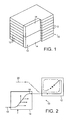
Referring to FIG. 1, an assembly 10 is shown for connecting optical fibres, the assembly 10 comprising a plurality of housings 12 for housing connections between optical fibres and a guide arrangement 13 for guiding optical fibres into said housings 12. The guide arrangement 13 comprises two guide devices 14 mounted side-by-side. The housings 12 may be provided in units of four housings, each unit being supplied with a guide device 14. As shown in FIG. 1, the housings 12 and the two guide devices 14 are in a stacked arrangement with the guide devices being adjacent to one another and fitted in the assembly relative to the housings. The stack may comprise only two guide devices fitted relative to the housings and as demand increases further housings and guide devices can be added to the stack.
FIG. 2 shows the routing of an optical fibre 16 of an optical fibre bundle 18 that has been separated from a primary cable and introduced to a guide device 14. Fibre 16 is guided through guide device 14 and into housing 12 where it is routed into position for splicing with fibre 20. Fibre 20 may be a secondary fibre leading to an individual customer location or may be a fibre of a fibre bundle from another primary cable. Fibres 16 and 20 are spliced together at position X in housing 12.
Referring to FIGS. 3 and 4, the guide device 14 is shown in more detail and provides an inlet port 22 into which an end portion 23′ of a tubular member 23 (FIG. 5) containing a fibre bundle 18 can be inserted through a substantially circular aperture for the passage of optical fibres into the guide arrangement. Inlet port 22 has a substantially cylindrical portion to correspond with the shape of the end portion 23′ of the tubular member 23 so that it can be push-fitted, or plugged, into the inlet port 22. Only a central section of the end portion 23′ shows through a longitudinal slit in the face of the guide device 14. Inlet port 22 also comprises a flanged portion against which the end portion 23′ of the tubular member 23 abuts when push-fitted into the inlet port 22 to limit travel of the tubular member into the inlet port 22. The flanged portion provides a slit through which optical fibres 16 extend from the tubular member 23 and into the guide device 14 along portion 24. Although the illustrated guide device is provided with only one inlet port 22, more than one such port may be provided to permit insertion of a fibre bundle 18 from more than one direction.
Outlet ports 26 are provided and each are associated with a respective housing 12 (not shown in FIGS. 3 and 4) for guiding optical fibres into the respective housing 12.
The guide device 14 comprises further ports including outlet ports 28 and inlet ports 30. Further outlet ports 28 are provided for guiding optical fibres to an adjacent like guide device and further inlet ports 30 are provided for receiving optical fibres from an adjacent like guide device. Respective further outlet and inlet ports 28, 30 of adjacent guide devices are arranged to be aligned so that optical fibres can readily be guided from the further outlet ports 28 of one guide device to the further inlet ports 30 of the adjacent guide device, as is shown in FIGS. 6 to 8 described below.
The guide device 14 comprises a plurality of fixed tracks 32′ and 32″. A first plurality of fixed tracks 32′ extend from inlet port 22 to outlet ports 26 and to further outlet ports 28 for guiding optical fibres from the inlet port 22 to the outlet ports 26 and to the further outlet ports 28. Also, a second plurality of fixed tracks 32″ extend from further inlet ports 30 to outlet ports 26 and to further outlet ports 28 for guiding optical fibres from the further inlet port 30 to the outlet ports 26 and to the further outlet ports 28. Over a portion of their lengths, fixed tracks 32′ and fixed tracks 32″ may be coextensive and over such a portion can guide fibres from either or both of the inlet port 22 and the further inlet ports 30. The fixed tracks illustrated are in the form of channels so that fibres can readily be pressed laterally into the fixed tracks. However, the fixed tracks may alternatively be bores through which optical fibres may be threaded. The illustrated channels have retaining tabs 34 for retaining optical fibres when introduced to the channels. A transparent cover (not shown) may also be fitted to the guide device for preventing dislodgement of the optical fibres once they are pressed into the channels. The cover is engageable with apertures 36 and barbs 38 on the guide device 14.
The fixed tracks 32′, 32″ have a radius of curvature, or bend radius, no less than a predetermined distance for reducing signal attenuation of optical fibres disposed in the fixed tracks 32′, 32″. The minimum radius of curvature is preferably 30 mm. The fixed tracks leading to the further outlet ports 28 of one guide device are aligned with and of a similar radius of curvature to the fixed tracks leading from the further inlet ports 30 of an adjacent like guide device. In this way, fixed tracks 32′, 32″ provide tracks which extend from the or each inlet port 22 of one guide device 14 to the outlet ports 26 of another guide device 14 and said tracks have a minimum bend radius for reducing signal attenuation in optical fibres disposed therein.
The guide device 14 is fitted to the housings by use of spigots 40 and barbs 42 which engage with optical fibre inlet ports (not shown) and recesses (not shown), respectively, provided in the housings 12. However, any suitable means of fitting the guide device 12 to the housings 14 may be provided as required.
FIGS. 5 to 8 show exemplary routing arrangements of optical fibres using one or more guide devices 14. After passing through the outlet ports 26 of the illustrated guide devices 14, the optical fibres 16 are introduced into associated housings (not shown).
FIG. 5 shows a guide device 14 with an optical fibre bundle 18 having eight fibres 16 guided on a two fibre per housing basis. The eight fibres are introduced to the guide device at the inlet port 22. Each group of two fibres follows a fixed track 32′ to a respective outlet port 26. Although the further ports 28, 30 and fixed tracks 32″ are not used in this arrangement, they are available for guiding fibres to and receiving fibres from adjacent guide devices as required.
FIG. 6 shows how fibre bundles 18 having twelve fibres 16 are routed on a two fibre per housing basis. Two fibre bundles 18 with twelve fibres in each are introduced at the inlet ports 22 of two of three guide devices 14. The fibres in the two bundles are separated into twelve groups of two fibres, each group being guided along a respective fixed track 32′, 32″ to an outlet port 26. In this arrangement, some fibres 16 introduced at the inlet port 22 of a first guide device 14, are guided along fixed tracks 32′ to a further outlet port 28 of the first guide device 14 and to the further inlet port 30 of an adjacent guide device 14 from which they are guided to an outlet port 26 of the adjacent guide device 14 along fixed tracks 32″. In other words, these optical fibres 16 are guided along tracks (including fixed tracks 32′ and fixed tracks 32″) which extend from the inlet port 22 of one device 14 to the outlet ports 26 of another of the guide devices 14 and these tracks have a minimum bend radius for preventing signal attenuation of the optical fibres disposed therein.
FIGS. 7 and 8 show, respectively, how optical fibre bundles 18 having eight and twelve fibres are routed on a one fibre per housing basis. In both arrangements, fibres introduced into a first guide device 14 are guided to outlet ports 26 of both the first and an adjacent guide device 14. In the FIG. 8 arrangement, optical fibres 16 are also guided to the outlet ports 26 of a third guide device 14 spaced from the first guide device 14. For example, one fibre is guided along a track (including fixed tracks 32′ and fixed tracks 32″) which extends sequentially through an inlet port (A) and a further outlet port (B) of a first device 14, through a further inlet port (C) and a further outlet port (D) of a second device 14, and through a further inlet port (E) and through an outlet port (F) of a third device 14.
Four specific routing arrangements have been described with reference to FIGS. 5 to 8, however other arrangements are possible. For instance, a stack of forty-eight housings may be provided with twelve guide devices and fibre may be guided from a lowest guide device to an outlet port of the highest guide device. It is the flexibility of the illustrated guide devices which is advantageous.

Claims (9)

What is claimed is:
1. An assembly for use in connecting optical fibres, the assembly comprising a plurality of housings for housing connections between optical fibres and a guide arrangement for guiding optical fibres into said housings, said guide arrangement comprising a plurality of guide devices mounted side-by-side, each guide device having at least one inlet port for the passage of optical fibres into the guide arrangement, a plurality of outlet ports associated with respective said housings for guiding optical fibres into the associated housing, a plurality of further inlet ports for receiving optical fibres from another one of said guide devices when positioned adjacent said guide device on one side thereof and a plurality of further outlet ports for guiding optical fibres to respective said further inlet ports of another one of said guide devices when positioned adjacent said guide device on another side thereof, said guide arrangement comprising at least two guide devices.
2. An assembly as claimed in claim 1, wherein the or each inlet port has a substantially cylindrical portion to correspond with the shape of a tubular member containing optical fibres so that a push-fit connection can be achieved by such a tubular member in the inlet port.
3. An assembly as claimed in claim 1, wherein each guide device provides a plurality of fixed tracks extending from said at least one inlet port to respective said outlet ports and to respective said further outlet ports for guiding optical fibres from the or each inlet port to respective said outlet ports and to respective said further outlet ports.
4. An assembly as claimed in claim 1, wherein each guide device provides a plurality of fixed tracks extending from said further inlet ports to respective said outlet ports and to respective said further outlet ports for guiding optical fibres from the further inlet ports to respective said outlet ports and to respective said further outlet ports.
5. An assembly as claimed in claim 3, wherein said fixed tracks are channels and have a bend radius not less than a predetermined distance for reducing signal attenuation in optical fibres disposed therein.
6. An assembly as claimed in claim 1, wherein the further outlet ports of one of said guide devices are adjacent the further inlet ports of another of said guide devices to assist in guidance of optical fibres between said further outlet parts of said one guide device and the further inlet ports of said another guide devices.
7. An assembly as claimed in claim 1, wherein fixed tracks provide tracks which extend from the or each inlet port of one of said devices to the outlet ports of another of said guide devices and said tracks have a bend radius not less than a predetermined distance for reducing signal attenuation in optical fibres disposed in the tracks.
8. An assembly as claimed in claim 5, wherein said fixed tracks have a bend radius of not less than 30 mm.
9. An assembly as claimed in claim 7, wherein said tracks have a bend radius of not less than 30 mm.
US10/162,766 2001-06-08 2002-06-06 Assembly for use in connecting optical fibers Expired - Lifetime US6764220B2 (en)

Applications Claiming Priority (3)

Application Number Priority Date Filing Date Title
EP01305038A EP1267190B1 (en) 2001-06-08 2001-06-08 An assembly for connectors of optical fibres
EP01305038.0 2001-06-08
EP01305038 2001-06-08

Publications (2)

Publication Number Publication Date
US20020186953A1 US20020186953A1 (en) 2002-12-12
US6764220B2 true US6764220B2 (en) 2004-07-20

Family

ID=8182017

Family Applications (1)

Application Number Title Priority Date Filing Date
US10/162,766 Expired - Lifetime US6764220B2 (en) 2001-06-08 2002-06-06 Assembly for use in connecting optical fibers

Country Status (5)

Country Link
US (1) US6764220B2 (en)
EP (1) EP1267190B1 (en)
AT (1) ATE291244T1 (en)
DE (1) DE60109429T2 (en)
ES (1) ES2240359T3 (en)

Cited By (25)

* Cited by examiner, † Cited by third party
Publication number Priority date Publication date Assignee Title
US20060233506A1 (en) * 2005-04-19 2006-10-19 Michael Noonan Fiber breakout with integral connector
US20070212005A1 (en) * 2006-03-09 2007-09-13 Adc Telecommunications, Inc. Mid-span breakout with helical fiber routing
US20070212009A1 (en) * 2006-03-09 2007-09-13 Adc Telecommunications, Inc. Fiber optic cable breakout configuration with retention block
US20070212003A1 (en) * 2006-03-09 2007-09-13 Adc Telecommunications, Inc. Mid-span breakout with potted closure
US20080080818A1 (en) * 2006-08-14 2008-04-03 Cobb John C Iii Factory Spliced Cable Assembly
US20080085091A1 (en) * 2006-10-10 2008-04-10 Dennis Ray Wells Systems and methods for securing a tether to a distribution cable
US20080089652A1 (en) * 2006-10-13 2008-04-17 Dennis Ray Wells Overmold zip strip
US20080187274A1 (en) * 2007-02-06 2008-08-07 Scott Carlson Polyurethane to polyethylene adhesion process
US20090022460A1 (en) * 2006-08-14 2009-01-22 Adc Telecommunications, Inc. Factory Spliced Cable Assembly
US20090060431A1 (en) * 2007-09-05 2009-03-05 Yu Lu Indoor Fiber Optic Distribution Cable
US20090202213A1 (en) * 2006-02-22 2009-08-13 Ian Griffiths Routing Device for Optical Fibre Systems
US7653282B2 (en) 2004-01-27 2010-01-26 Corning Cable Systems Llc Multi-port optical connection terminal
US7680388B2 (en) 2004-11-03 2010-03-16 Adc Telecommunications, Inc. Methods for configuring and testing fiber drop terminals
US7740409B2 (en) 2007-09-19 2010-06-22 Corning Cable Systems Llc Multi-port optical connection terminal
US7805044B2 (en) 2004-11-03 2010-09-28 Adc Telecommunications, Inc. Fiber drop terminal
US8121456B2 (en) 2006-08-09 2012-02-21 Adc Telecommunications, Inc. Cable payout systems and methods
US8625951B2 (en) 2010-10-08 2014-01-07 3M Innovative Properties Company Modular support system for optical fiber trays
US8755663B2 (en) 2010-10-28 2014-06-17 Corning Cable Systems Llc Impact resistant fiber optic enclosures and related methods
US8873926B2 (en) 2012-04-26 2014-10-28 Corning Cable Systems Llc Fiber optic enclosures employing clamping assemblies for strain relief of cables, and related assemblies and methods
US8885998B2 (en) 2010-12-09 2014-11-11 Adc Telecommunications, Inc. Splice enclosure arrangement for fiber optic cables
US8915659B2 (en) 2010-05-14 2014-12-23 Adc Telecommunications, Inc. Splice enclosure arrangement for fiber optic cables
US20150098684A1 (en) * 2013-10-07 2015-04-09 Tyco Electronics Corporation Modular break out for cable assembly
US9069151B2 (en) 2011-10-26 2015-06-30 Corning Cable Systems Llc Composite cable breakout assembly
US20180052287A1 (en) * 2016-08-19 2018-02-22 Ortronics, Inc. Internal Harnessing Members and Method for Bend Control of Optical Fibers in Connector Assemblies
US11079555B2 (en) 2019-03-02 2021-08-03 Senko Advanced Components, Inc. Fiber management enclosure for a fiber optic connector assembly and method of use

Families Citing this family (2)

* Cited by examiner, † Cited by third party
Publication number Priority date Publication date Assignee Title
ES2240359T3 (en) 2001-06-08 2005-10-16 Pirelli General Plc ASSEMBLY FOR OPTICAL FIBER CONNECTORS.
EP1428056A2 (en) 2001-09-07 2004-06-16 PIRELLI GENERAL plc Joining optical fibres

Citations (20)

* Cited by examiner, † Cited by third party
Publication number Priority date Publication date Assignee Title
US4374596A (en) 1978-06-30 1983-02-22 Josef Schlemmer Gmbh Pipe-form connector for cable ducts
US5125060A (en) 1991-04-05 1992-06-23 Alcatel Na Cable Systems, Inc. Fiber optic cable having spliceless fiber branch and method of making
US5142606A (en) * 1990-01-22 1992-08-25 Porta Systems Corp. Optical fiber cable distribution frame and support
US5249252A (en) * 1992-08-31 1993-09-28 Alcatel Network Systems, Inc. Optical fiber splice tray with cable tray hinge
GB2283373A (en) 1993-10-01 1995-05-03 Bicc Plc Breakout
JPH0875970A (en) 1994-09-07 1996-03-22 Hitachi Cable Ltd Tube branch cable, tube for branch and wiring method therefor
US5511144A (en) * 1994-06-13 1996-04-23 Siecor Corporation Optical distribution frame
US5513293A (en) * 1994-11-29 1996-04-30 At&T Corp. Optical backplane for a telecommunication distribution frame
GB2300488A (en) 1995-05-04 1996-11-06 Bicc Plc Optical fibre management system having splice tray and splitter mat
JPH1062668A (en) 1996-08-21 1998-03-06 Sumitomo Electric Ind Ltd Connecting method for pneumatic force feeding pipe
US5737475A (en) * 1997-01-17 1998-04-07 Leviton Manufacturing Co., Inc. Universal multimedia connection unit
US5754723A (en) * 1993-07-08 1998-05-19 Raychem Gmbh Multi-filament splice enclosures
US5764843A (en) 1993-09-08 1998-06-09 N.V. Raychem S.A. Optical fibre organizer
US5802237A (en) * 1997-04-18 1998-09-01 Minnesota Mining And Manufacturing Company Optical fiber organizer
GB2325531A (en) 1997-05-19 1998-11-25 Pirelli General Plc Optical fibre connector organiser
JPH1151852A (en) 1997-08-06 1999-02-26 Sumitomo Electric Ind Ltd Pipe tester
EP0980012A1 (en) 1998-08-13 2000-02-16 Siemens Aktiengesellschaft Cable feed in adapter for cable entrances with optical cable arrangements
EP1026530A1 (en) 1999-02-04 2000-08-09 Alcatel Optical fibre organiser
GB2351333A (en) 1999-04-28 2000-12-27 Donal Joseph Dunne Trunking assembly for transmission cables
EP1267190A1 (en) 2001-06-08 2002-12-18 PIRELLI GENERAL plc An assembly for connectors of optical fibres

Patent Citations (23)

* Cited by examiner, † Cited by third party
Publication number Priority date Publication date Assignee Title
US4374596A (en) 1978-06-30 1983-02-22 Josef Schlemmer Gmbh Pipe-form connector for cable ducts
US5142606A (en) * 1990-01-22 1992-08-25 Porta Systems Corp. Optical fiber cable distribution frame and support
US5125060A (en) 1991-04-05 1992-06-23 Alcatel Na Cable Systems, Inc. Fiber optic cable having spliceless fiber branch and method of making
US5249252A (en) * 1992-08-31 1993-09-28 Alcatel Network Systems, Inc. Optical fiber splice tray with cable tray hinge
US5754723A (en) * 1993-07-08 1998-05-19 Raychem Gmbh Multi-filament splice enclosures
US5764843A (en) 1993-09-08 1998-06-09 N.V. Raychem S.A. Optical fibre organizer
GB2283373A (en) 1993-10-01 1995-05-03 Bicc Plc Breakout
US5511144A (en) * 1994-06-13 1996-04-23 Siecor Corporation Optical distribution frame
JPH0875970A (en) 1994-09-07 1996-03-22 Hitachi Cable Ltd Tube branch cable, tube for branch and wiring method therefor
US5513293A (en) * 1994-11-29 1996-04-30 At&T Corp. Optical backplane for a telecommunication distribution frame
GB2300488A (en) 1995-05-04 1996-11-06 Bicc Plc Optical fibre management system having splice tray and splitter mat
JPH1062668A (en) 1996-08-21 1998-03-06 Sumitomo Electric Ind Ltd Connecting method for pneumatic force feeding pipe
US5737475A (en) * 1997-01-17 1998-04-07 Leviton Manufacturing Co., Inc. Universal multimedia connection unit
US5802237A (en) * 1997-04-18 1998-09-01 Minnesota Mining And Manufacturing Company Optical fiber organizer
GB2325531A (en) 1997-05-19 1998-11-25 Pirelli General Plc Optical fibre connector organiser
WO1998053354A1 (en) 1997-05-19 1998-11-26 Pirelli General Plc Connecting optical fibres
US6418264B1 (en) 1997-05-19 2002-07-09 Pirelli General Plc Connecting optical fibres
JPH1151852A (en) 1997-08-06 1999-02-26 Sumitomo Electric Ind Ltd Pipe tester
EP0980012A1 (en) 1998-08-13 2000-02-16 Siemens Aktiengesellschaft Cable feed in adapter for cable entrances with optical cable arrangements
EP1026530A1 (en) 1999-02-04 2000-08-09 Alcatel Optical fibre organiser
US6282360B1 (en) 1999-02-04 2001-08-28 Alcatel Optical fiber organizer
GB2351333A (en) 1999-04-28 2000-12-27 Donal Joseph Dunne Trunking assembly for transmission cables
EP1267190A1 (en) 2001-06-08 2002-12-18 PIRELLI GENERAL plc An assembly for connectors of optical fibres

Non-Patent Citations (2)

* Cited by examiner, † Cited by third party
Title
Griffiths et al., "Connecting Optical Fibres", U.S. patent application No. 10/170,545, filed Jun. 14, 2002, Publ. # 2002/0191942.
Shinichi; "Optical Fiber Cable for Pneumatic Force Feeding" ; Patent Abstracts of Japan, of JP 10-197765 A, Jul. 31, 1998.

Cited By (39)

* Cited by examiner, † Cited by third party
Publication number Priority date Publication date Assignee Title
US7653282B2 (en) 2004-01-27 2010-01-26 Corning Cable Systems Llc Multi-port optical connection terminal
US10890729B2 (en) 2004-11-03 2021-01-12 Commscope Technologies Llc Fiber drop terminal and bracket
US7680388B2 (en) 2004-11-03 2010-03-16 Adc Telecommunications, Inc. Methods for configuring and testing fiber drop terminals
US7805044B2 (en) 2004-11-03 2010-09-28 Adc Telecommunications, Inc. Fiber drop terminal
US9851522B2 (en) 2004-11-03 2017-12-26 Commscope Technologies Llc Fiber drop terminal
US11567278B2 (en) 2004-11-03 2023-01-31 Commscope Technologies Llc Fiber drop terminal
US10042136B2 (en) 2004-11-03 2018-08-07 Commscope Technologies Llc Fiber drop terminal
US20100014824A1 (en) * 2005-04-19 2010-01-21 Adc Telecommunications, Inc. Loop back plug and method
US11347008B2 (en) 2005-04-19 2022-05-31 Commscope Technologies Llc Fiber optic connection device with ruggedized tethers
US20060233506A1 (en) * 2005-04-19 2006-10-19 Michael Noonan Fiber breakout with integral connector
US20060257092A1 (en) * 2005-04-19 2006-11-16 Yu Lu Loop back plug and method
US8041178B2 (en) 2005-04-19 2011-10-18 Adc Telecommunications, Inc. Loop back plug and method
US20090202213A1 (en) * 2006-02-22 2009-08-13 Ian Griffiths Routing Device for Optical Fibre Systems
US20070212003A1 (en) * 2006-03-09 2007-09-13 Adc Telecommunications, Inc. Mid-span breakout with potted closure
US20070212009A1 (en) * 2006-03-09 2007-09-13 Adc Telecommunications, Inc. Fiber optic cable breakout configuration with retention block
US20070212005A1 (en) * 2006-03-09 2007-09-13 Adc Telecommunications, Inc. Mid-span breakout with helical fiber routing
US20100080514A1 (en) * 2006-03-09 2010-04-01 Adc Telecommunications, Inc. Fiber optic cable breakout configuration with retention block
US8121456B2 (en) 2006-08-09 2012-02-21 Adc Telecommunications, Inc. Cable payout systems and methods
US20090022460A1 (en) * 2006-08-14 2009-01-22 Adc Telecommunications, Inc. Factory Spliced Cable Assembly
US7840109B2 (en) 2006-08-14 2010-11-23 Adc Telecommunications, Inc. Factory spliced cable assembly
US20080080818A1 (en) * 2006-08-14 2008-04-03 Cobb John C Iii Factory Spliced Cable Assembly
US20080085091A1 (en) * 2006-10-10 2008-04-10 Dennis Ray Wells Systems and methods for securing a tether to a distribution cable
US20080089652A1 (en) * 2006-10-13 2008-04-17 Dennis Ray Wells Overmold zip strip
US20080187274A1 (en) * 2007-02-06 2008-08-07 Scott Carlson Polyurethane to polyethylene adhesion process
US7769261B2 (en) 2007-09-05 2010-08-03 Adc Telecommunications, Inc. Fiber optic distribution cable
US20090060431A1 (en) * 2007-09-05 2009-03-05 Yu Lu Indoor Fiber Optic Distribution Cable
US7740409B2 (en) 2007-09-19 2010-06-22 Corning Cable Systems Llc Multi-port optical connection terminal
US9798085B2 (en) 2010-05-14 2017-10-24 Commscope Technologies Llc Splice enclosure arrangement for fiber optic cables
US8915659B2 (en) 2010-05-14 2014-12-23 Adc Telecommunications, Inc. Splice enclosure arrangement for fiber optic cables
US8625951B2 (en) 2010-10-08 2014-01-07 3M Innovative Properties Company Modular support system for optical fiber trays
US8755663B2 (en) 2010-10-28 2014-06-17 Corning Cable Systems Llc Impact resistant fiber optic enclosures and related methods
US8885998B2 (en) 2010-12-09 2014-11-11 Adc Telecommunications, Inc. Splice enclosure arrangement for fiber optic cables
US9069151B2 (en) 2011-10-26 2015-06-30 Corning Cable Systems Llc Composite cable breakout assembly
US8873926B2 (en) 2012-04-26 2014-10-28 Corning Cable Systems Llc Fiber optic enclosures employing clamping assemblies for strain relief of cables, and related assemblies and methods
US20150098684A1 (en) * 2013-10-07 2015-04-09 Tyco Electronics Corporation Modular break out for cable assembly
US20180052287A1 (en) * 2016-08-19 2018-02-22 Ortronics, Inc. Internal Harnessing Members and Method for Bend Control of Optical Fibers in Connector Assemblies
US10162129B2 (en) * 2016-08-19 2018-12-25 Ortronics, Inc. Internal harnessing members and method for bend control of optical fibers in connector assemblies
US11079555B2 (en) 2019-03-02 2021-08-03 Senko Advanced Components, Inc. Fiber management enclosure for a fiber optic connector assembly and method of use
US11175465B2 (en) 2019-03-02 2021-11-16 Senko Advanced Components, Inc. Fiber management enclosure for a fiber optic connector assembly and method of use

Also Published As

Publication number Publication date
EP1267190A1 (en) 2002-12-18
ATE291244T1 (en) 2005-04-15
DE60109429T2 (en) 2006-05-11
US20020186953A1 (en) 2002-12-12
DE60109429D1 (en) 2005-04-21
ES2240359T3 (en) 2005-10-16
EP1267190B1 (en) 2005-03-16

Similar Documents

Publication Publication Date Title
US6764220B2 (en) Assembly for use in connecting optical fibers
US6810194B2 (en) Connecting optical fibers
US6385381B1 (en) Fiber optic interconnection combination closure
AU691831B2 (en) Optical fibre organizer
US5717811A (en) Optical fiber organizer
AU698186B2 (en) Optical fibre organizer
CA2761129C (en) Port mapping for series connected fiber optic terminals
EP3384336B1 (en) Cable distribution system with fan out devices
CN1125326A (en) Housing for optical components
JPH08508348A (en) Optical fiber knitting machine
CN110462478B (en) Optical connector and termination module
EP2558898B1 (en) Network device with drop port adapter connector and pass through-port multifibre adapter
US20220365306A1 (en) Terminal system assemblies with breakout/adapter modules
US6442322B1 (en) Optical fiber management device
EP2141528B1 (en) Optical fibre distribution box
US20220252817A1 (en) Fiber optic fanout with intermediate portions and method of assembly
GB2286691A (en) Universal connection unit for optical waveguides
US10578823B2 (en) Wall cabinets and fiber management trays
AU2015204389B2 (en) Port mapping for series connected fiber optic terminals
AU2022233700A1 (en) Optical connectivity module and chassis

Legal Events

Date Code Title Description
AS Assignment

Owner name: PIRELLI GENERAL PLC, UNITED KINGDOM

Free format text: ASSIGNMENT OF ASSIGNORS INTEREST;ASSIGNORS:KERRY, JOHN;GRIFFITHS, IAN JAMES;JONES, MALCOLM OWEN;REEL/FRAME:013164/0136

Effective date: 20020617

STCF Information on status: patent grant

Free format text: PATENTED CASE

CC Certificate of correction
AS Assignment

Owner name: PRYSMIAN CABLES & SYSTEMS LIMITED, UNITED KINGDOM

Free format text: CHANGE OF NAME;ASSIGNOR:PIRELLI GENERAL PLC;REEL/FRAME:020064/0276

Effective date: 20051003

FPAY Fee payment

Year of fee payment: 4

REMI Maintenance fee reminder mailed
FPAY Fee payment

Year of fee payment: 8

FPAY Fee payment

Year of fee payment: 12