US6801308B2 - Method and apparatus for measuring chromatic dispersion in optical fibers - Google Patents
Method and apparatus for measuring chromatic dispersion in optical fibers Download PDFInfo
- Publication number
- US6801308B2 US6801308B2 US10/369,664 US36966403A US6801308B2 US 6801308 B2 US6801308 B2 US 6801308B2 US 36966403 A US36966403 A US 36966403A US 6801308 B2 US6801308 B2 US 6801308B2
- Authority
- US
- United States
- Prior art keywords
- waveguide
- signal
- pump
- probe
- wavelength
- Prior art date
- Legal status (The legal status is an assumption and is not a legal conclusion. Google has not performed a legal analysis and makes no representation as to the accuracy of the status listed.)
- Expired - Lifetime
Links
Images


Classifications
-
- G—PHYSICS
- G01—MEASURING; TESTING
- G01M—TESTING STATIC OR DYNAMIC BALANCE OF MACHINES OR STRUCTURES; TESTING OF STRUCTURES OR APPARATUS, NOT OTHERWISE PROVIDED FOR
- G01M11/00—Testing of optical apparatus; Testing structures by optical methods not otherwise provided for
- G01M11/30—Testing of optical devices, constituted by fibre optics or optical waveguides
- G01M11/33—Testing of optical devices, constituted by fibre optics or optical waveguides with a light emitter being disposed at one fibre or waveguide end-face, and a light receiver at the other end-face
- G01M11/333—Testing of optical devices, constituted by fibre optics or optical waveguides with a light emitter being disposed at one fibre or waveguide end-face, and a light receiver at the other end-face using modulated input signals
-
- G—PHYSICS
- G01—MEASURING; TESTING
- G01M—TESTING STATIC OR DYNAMIC BALANCE OF MACHINES OR STRUCTURES; TESTING OF STRUCTURES OR APPARATUS, NOT OTHERWISE PROVIDED FOR
- G01M11/00—Testing of optical apparatus; Testing structures by optical methods not otherwise provided for
- G01M11/30—Testing of optical devices, constituted by fibre optics or optical waveguides
- G01M11/33—Testing of optical devices, constituted by fibre optics or optical waveguides with a light emitter being disposed at one fibre or waveguide end-face, and a light receiver at the other end-face
- G01M11/338—Testing of optical devices, constituted by fibre optics or optical waveguides with a light emitter being disposed at one fibre or waveguide end-face, and a light receiver at the other end-face by measuring dispersion other than PMD, e.g. chromatic dispersion
Definitions
- the present application relates to a method and apparatus for measuring chromatic dispersion in optical waveguides for optical communication, and more specifically to such method and apparatus using Raman effect.
- Chromatic dispersion occurs in optical waveguides due to differences of propagation speeds at various wavelengths. Therefore, the optical pulse signal expands as it travels along the waveguide, deforming the waveform and causing crosstalk between adjacent channels.
- Inagaki describes another pulse delaying method based on transmitting a laser pulse generated by Raman oscillation through a sample fiber.
- a reference wavelength light and an object wavelength light are received and a delay time of the object wavelength light relative to the reference wavelength light is measured as a factor of a chromatic dispersion of the sample fiber.
- the Raman gain takes place in the measuring instrument, and not in the waveguide under test.
- chromatic dispersion is measured by determining the phase shift of a modulated signal transmitted along an optical fiber.
- phase-shift methods used for measuring chromatic dispersion.
- an input signal is modulated and is transmitted through the optical fiber for which chromatic dispersion is to be measured.
- the phase of the transmitted signal is compared to the phase of a fixed reference signal, which for example, may have been simultaneously transmitted through the fiber or may have been used to modulated the input signal.
- the phase difference of different input wavelengths relative to the fixed reference wavelength provides the group velocity delay, which is subsequently used to calculate the chromatic dispersion.
- the dispersion is measured directly, without calculating the group velocity delay.
- the dispersion is calculated from a the phase difference between a first modulated signal at a first wavelength and a second modulated signal at a second wavelength.
- the phase differences are obtained using electronic phase detectors.
- Phase-shift methods are advantageously more accurate. Moreover, a simple filter or monochromator can be used as a wavelength selector. Disadvantageously, phase shift methods require communication between the input and output ends of the device under test (DUT) (e.g., the optical fiber). It is desirable to measure chromatic dispersion without requiring phase information, i.e. without extracting phase properties of the signal at both ends of the waveguide which requires complex electronics.
- DUT device under test
- Nishi et al. describe a method and apparatus for measuring a distribution of zero-dispersion wavelengths.
- this method and apparatus an optical pulse and a pump signal are launched into an optical fiber and the amplification of the pulse signal resulting from modulation instability induced by the pump signal is detected from the back-scattered light waveform of the pulse signal.
- the apparatus and method proposed by Nishi et al. only requires measurements at one end of the optical fiber.
- the apparatus and method proposed by Nishi et al. does not provide information regarding group delay and/or wavelength dependence of the dispersion.
- a modulated pump signal and a probe signal are propagated through a waveguide medium and the ratio of the modulation power of the pump signal to the modulation power of the output signal is determined and related to the chromatic dispersion.
- the Raman gain varies along the fiber spatially and temporally due to the modulated pump signal. These variations get transferred to the probe signal.
- the efficiency of the transfer between the pump modulation and the probe modulation at the output of the waveguide depends on the difference in group velocity of the signals, which relates to the chromatic dispersion between the two wavelengths. The amplitude of both signal modulations are measured and related to the dispersion.
- the probe signal is provided by a tunable laser diode.
- the probe signal corresponds to amplified spontaneous emission generated by the modulated pump signal due to spontaneous Raman scattering in the fiber.
- a method of measuring group delay in an optical waveguide comprising the steps of: a) providing a modulated pump signal to the optical waveguide; b) allowing the pump signal to propagate within the optical waveguide so as to generate gain within the waveguide, the gain having the modulation of the pump signal impressed thereon; c) varying the modulation frequency of the pump signal; d) measuring a frequency response of the modulated gain while the modulation frequency of the pump signal is varied; and determining the group delay from the frequency response of the modulated gain.
- a method for measuring chromatic dispersion of an optical waveguide having an input end and an output end comprising the steps of: a) inputting a modulated pump signal into the input end of the waveguide to generate Raman gain in the waveguide, b) inputting a probe signal into the input end of the waveguide, the probe signal having a wavelength that is within Raman gain band characteristic of the waveguide, c) combining the pump signal and the probe signal at the input end of the waveguide, d) impressing the modulation of the pump signal on the probe signal through temporal and spatial Raman gain modulation in the waveguide, e) varying the modulation frequency of the pump signal, f) measuring frequency response of the probe signal at the output end of the waveguide while the modulation frequency of the pump signal is varied, g) determining the group delay from the frequency response of the probe signal, h) varying the wavelength of the probe signal, i) repeating steps a) to g) for different probe wavelengths to determine
- an apparatus for measuring chromatic dispersion of a waveguide having an input end and an output end comprising: a Raman pump source operatively coupled to the input end of the waveguide, the Raman pump source for providing a pump signal to the input end; a modulator coupled to the Raman pump source, the modulator for modulating the Raman pump signal; and, a detector operatively coupled to the output end of the waveguide, the detector for measuring, at the output end of the waveguide, a frequency response of a probe signal simultaneously propagating through the waveguide with the modulated Raman pump signal.
- the apparatus may further comprise combining means for combining the pump signal and a probe signal at the input end of the waveguide, and means for separating the pump signal and the probe signal at the output end of the waveguide.
- the modulator may be an external intensity modulator operatively connected to the pump signal source. It may be embodied by an electrical modulator or by an optical modulator.
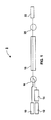
- FIG. 1 is a block diagram of an apparatus for measuring chromatic dispersion according to one embodiment of the invention
- FIG. 2 is a graph illustrating relationship between experimental values and the theoretical values of chromatic dispersion
- FIG. 3 is a graph of experimental group delay vs. wavelength based on Sellmeier's equation.
- FIG. 4 is a block diagram of an apparatus for measuring chromatic dispersion according to another embodiment of the invention.
- the instant invention relates to an apparatus and method for measuring chromatic dispersion using Raman scattering.
- Raman scattering is a non-linear process that occurs when a high energy pump photon excites a molecule within a “gain medium” into a higher energy state, i.e., virtual level, which subsequently decays to a lower level by emitting another photon within the “gain spectrum” of the molecule.
- the emitted photon When the decay occurs naturally, the emitted photon is scattered with random time, frequency, and polarization, and the process is referred to as Spontaneous Raman scattering. If, however, a signal photon within the “gain spectrum” collides with the excited molecule, then the emitted photon is scattered with the same frequency, phase, and polarization of the signal photon and the process is referred to as Stimulated Raman scattering.
- Amplified spontaneous emission (ASE) is the process in which the scattered photons from the spontaneous process induces stimulated Raman scattering.
- the apparatus 5 includes a probe laser 10 that provides a continuous signal at the wavelength(s) at which chromatic dispersion is to be measured, a pump laser 12 that provides a continuous signal at the desired Raman pumping wavelength, and a modulator 14 coupled to the pump laser that intensity or amplitude modulates the pump signal emitted by the pump laser 12 .
- the pumping wavelength is typically of higher energy and therefore of shorter wavelength than the probe laser wavelength.
- the pump wavelength used is determined by the media under test. Usually, for silica glass, it is desired to have the central wavelength of the probe band to be about 13.2 THz lower than the pump wavelength. Since relatively little gain is needed in the measurement of chromatic dispersion and the Raman gain curve spans a relatively wide wavelength range, a single pump laser should be sufficient for each communication band (L, C, S, corresponding to 1565-1620 nm, 1525-1565 nm and 1450 nm to 1520 nm etc).
- the apparatus 5 also includes a multiplexer 16 that combines the pump signal and the probe signal.
- the combined signal is input to a waveguide 18 .
- the waveguide 18 has a length that is sufficient to provide measurable chromatic dispersion.
- the waveguide is a single-mode optical fiber that is at least one kilometer long. Due to the inherent nonlinear properties of the waveguide 18 , some coupling takes place between the pump signal and the probe signal in the waveguide. In particular, as the two beams propagate through the waveguide 18 they experience stimulated Raman scattering, and as result the probe signal is amplified. The modulation of the pump signal causes the amount of gain to vary spatially along the waveguide.
- the combined signal is separated in a demultiplexer 20 back into the pump signal and the probe signal.
- the latter is presented to a detector 22 .
- the dispersion is calculated using the power detected at the given modulation frequency (i.e., the frequency response).
- ⁇ is the relative group delay
- ⁇ p is the fiber loss per unit length at the pump wavelength
- ⁇ equals 2 ⁇ f
- f is modulation frequency of a pump
- L is the length of the fiber.
- ⁇ ⁇ s ( 2 )
- ⁇ s is the wavelength of the probe being used.
- FIG. 2 represents a relationship between experimental data of chromatic dispersion (squares) and the theoretical values (line). It can be seen that the relationship (fit) is very good.
- Equation (3) a, b and c are parameters determined by fitting experimental data to Sellmeier's equation.
- the chromatic dispersion can be derived from Eq. (3) by using equation (2).
- FIG. 3 The results obtained using the iterative approach with the combination of Sellmeier's equation are presented in FIG. 3 . It can be seen in FIG. 3 that the relationship between the group delay and the wavelength corresponds well to the Sellmeier's equation with parameters a, b and c as shown in the FIG. 3 .
- the instant invention provides an apparatus for determining group delay and/or chromatic dispersion, that is relatively simple and inexpensive.
- the probe laser 10 is a tunable laser diode that provides a 6 mW signal beam and that scans between 1500-1580 nm
- the pump laser 12 is a grating stabilized laser diode that provides a 130 mW signal beam at 1447 nm
- the modulator 14 is an external modulator designed to sinusoidally amplitude modulate the pump signal as the modulation frequency is swept through a range of 300 kHz to 150 MHz
- the waveguide 18 is a 24 km single-mode optical fiber
- the detector 22 includes a photodiode, a transimpedance amplifier and a tunable band-pass filter at the frequency of modulation, followed by an amplitude detector to detect the signal power at the modulation frequency.
- the probe laser 10 includes a broadband light source coupled to a monochromator or optical tunable filter, and/or the modulator includes an RF network analyzer having an input coupled to the detector 22 and an output connected to the pump laser 12 .
- the filter is optionally positioned upstream or downstream from the optical waveguide 18 . In the latter case, the optical tunable filter optionally replaces the demultiplexor 20 .
- the method and apparatus described above enables the determination of chromatic dispersion in a waveguide by using spatial and temporal Raman gain modulation.
- the Raman effect gives rise to a transfer of modulation from the pump signal to the probe signal.
- the efficiency of the transfer is controlled by the dispersion. Dispersion can thus be determined from this relationship.
- the probe signal is not provided by a tunable laser diode, but rather corresponds to the ASE generated from the pump signal.
- the apparatus 40 includes a pump laser 42 , an optical waveguide 44 , a tunable optical filter 46 , and a detector 48 .
- the optical waveguide 44 which for exemplary purposes is illustrated as an optical fibre, has an input end coupled to the pump laser 42 and an output end coupled to the tunable filter 46 .
- Each end of the optical fiber 44 is connected via a splice or connector 44 a , 44 b .
- the optical fiber 44 is connected to the pump laser 42 and/or tunable filter 46 in another manner, such as with a wavelength division multiplexer (WDM).
- WDM wavelength division multiplexer
- the apparatus 40 also includes a modulator 50 for modulating the pump signal.
- the modulator 40 is depicted as a network analyzer that is coupled to both the detector 48 and the pump laser 42 .
- an output of the detector 48 is coupled to an input of the network analyzer 50
- the output of the network analyzer is coupled to an input of the pump laser 42 .
- the network analyzer is used to sweep the frequency of modulation of the pump signal and record the magnitude of the frequency coming out of the detector 48 .
- the optical fiber 44 is a single-mode optical fiber
- the pump laser 42 is a grating stabilized laser diode emitting at 1447 nm
- the tunable filter 46 is a narrow-bandpass filter
- the detector is a photo-diode.
- the detector 48 is sufficiently sensitive to detect ASE.
- the detector 48 includes both a photo-diode and an erbium doped fiber amplifier (EDFA).
- EDFA erbium doped fiber amplifier
- the network analyzer is replaced with an external modulator coupled to the pump laser 42 and the detector 48 is designed to include an electric filter or lock-in (LI) amplifier to determine the amplitude of the transferred modulation.
- LI electric filter or lock-in
- the pump laser 42 provides a continuous pump signal that is modulated by the network analyzer 50 .
- the pump signal is sinusoidally modulated at 300 kHz.
- the modulated pump signal propagates through the optical fiber 44 . Wherever the pump signal interacts with the fiber 44 , both stimulated and spontaneous Raman scattering occurs, the strongest effects occurring at the input of the optical fiber (i.e., near 44 a ).
- the ASE generated by these processes propagates through the optical fiber 44 with the pump signal. As the ASE and the pump signal propagate through the optical fiber 44 , some more coupling occurs, and modulation from the intense pump signal is transferred to the lower intensity ASE signal. In other words, since the pump is modulated the ASE varies both spatially and temporally.
- the ASE is a broad wavelength signal covering the entire Raman gain spectrum that is very small in intensity and does not substantially affect the pump signal.
- the modulated ASE and pump signals are output from the optical fiber 44 , they are transmitted to the tunable optical filter 46 .
- the tunable filter 46 filters out all wavelengths, including the pump wavelength, from the wavelength or wavelength range of interest.
- the resulting narrow-band modulated signal is output the tunable filter 46 and the amplitude of the modulation is measured by the detector 48 and/or network analyzer 50 .
- the ratio of the modulation power of the pump to the modulation power of the ASE, normalized to 1 at the peak, i.e., the normalized frequency response or transfer function, is calculated.
- This process is repeated as the modulator 50 is swept through a predetermined frequency range, which for example is from 300 kKz to 150 MHz.
- the experiment curve corresponding to a plot of the transfer function versus the modulation frequency is used with Equation 1 to calculate ⁇ , the wavelength dependent relative group delay between the ASE and the pump signal.
- ⁇ is calculated at the wavelength of the tunable optical filter 46 .
- D( ⁇ ) the entire process is repeated for selected wavelengths as the tunable filter 46 is swept through a predetermined wavelength range, for example from 1500-1580 nm.
- the dispersion is calculated from Equation 2, as discussed above.
- the instant invention obviates the use of pulses and/or phase detectors, thus lowering the cost and complexity, relative to the prior art.
- the chromatic dispersion occurs in the same optical waveguide and at the same time that the Raman gain occurs.
- the method and apparatus in accordance with the instant invention allows measurements to be made at only one end of the DUT (i.e., the modulation transferred to the probe/ASE signal is compared to the known modulation injected into the pump signal).
- the apparatus and method discussed with respect to FIG. 4 generates its own probe signal, thus eliminating the need for a tunable laser and further simplifying the design.
- a continuous wave broadband probe source in the embodiment illustrated in FIG. 4, to lessen the burden on the detection system and still obviate the need for a tunable laser.
Abstract
Description


Claims (20)

Priority Applications (1)
| Application Number | Priority Date | Filing Date | Title |
|---|---|---|---|
| US10/369,664 US6801308B2 (en) | 2001-05-21 | 2003-02-21 | Method and apparatus for measuring chromatic dispersion in optical fibers |
Applications Claiming Priority (3)
| Application Number | Priority Date | Filing Date | Title |
|---|---|---|---|
| US29198501P | 2001-05-21 | 2001-05-21 | |
| US09/909,793 US20020176070A1 (en) | 2001-05-21 | 2001-07-23 | Method and apparatus for measuring chromatic dispersion in optical fibers |
| US10/369,664 US6801308B2 (en) | 2001-05-21 | 2003-02-21 | Method and apparatus for measuring chromatic dispersion in optical fibers |
Related Parent Applications (1)
| Application Number | Title | Priority Date | Filing Date |
|---|---|---|---|
| US09/909,793 Continuation-In-Part US20020176070A1 (en) | 2001-05-21 | 2001-07-23 | Method and apparatus for measuring chromatic dispersion in optical fibers |
Publications (2)
| Publication Number | Publication Date |
|---|---|
| US20030151736A1 US20030151736A1 (en) | 2003-08-14 |
| US6801308B2 true US6801308B2 (en) | 2004-10-05 |
Family
ID=46282033
Family Applications (1)
| Application Number | Title | Priority Date | Filing Date |
|---|---|---|---|
| US10/369,664 Expired - Lifetime US6801308B2 (en) | 2001-05-21 | 2003-02-21 | Method and apparatus for measuring chromatic dispersion in optical fibers |
Country Status (1)
| Country | Link |
|---|---|
| US (1) | US6801308B2 (en) |
Cited By (2)
| Publication number | Priority date | Publication date | Assignee | Title |
|---|---|---|---|---|
| US20050168802A1 (en) * | 2003-10-17 | 2005-08-04 | Alcatel | Fiber optic transmission system using Raman effect amplification |
| US7489880B2 (en) * | 2002-04-30 | 2009-02-10 | Pivotal Decisions, Llc | Apparatus and method for measuring the dispersion of a fiber span |
Families Citing this family (6)
| Publication number | Priority date | Publication date | Assignee | Title |
|---|---|---|---|---|
| US7486743B2 (en) * | 2003-12-29 | 2009-02-03 | Intel Corporation | Device and method of measuring frequency domain response in RF modulator |
| US7426021B2 (en) * | 2004-11-29 | 2008-09-16 | Expo Electro- Optical Engineering Inc. | Interferometric optical analyzer and method for measuring the linear response of an optical component |
| US9602225B2 (en) * | 2011-06-28 | 2017-03-21 | Keysight Technologies, Inc. | Impairment compensation |
| US9667358B2 (en) | 2011-06-28 | 2017-05-30 | Keysight Technologies, Inc. | Impairment compensation |
| WO2015157911A1 (en) * | 2014-04-15 | 2015-10-22 | 华为技术有限公司 | Optical waveguide group velocity delay measurement device and method |
| CN114370992B (en) * | 2021-12-31 | 2023-06-20 | 中山大学 | Microcavity dispersion detection device |
Citations (6)
| Publication number | Priority date | Publication date | Assignee | Title |
|---|---|---|---|---|
| JPH02281122A (en) | 1989-04-24 | 1990-11-16 | Nippon Telegr & Teleph Corp <Ntt> | Apparatus for measuring dispersion and distribution of wavelength of optical fiber |
| US5189483A (en) | 1989-02-28 | 1993-02-23 | Fujitsu Limited | Apparatus for measurement of chromatic dispersion in a single mode optical fiber |
| US5532868A (en) * | 1994-09-23 | 1996-07-02 | At&T Corp. | Apparatus and method for compensating chromatic dispersion produced in optical phase conjugation or other types of optical signal conversion |
| US5724126A (en) * | 1994-05-06 | 1998-03-03 | Nippon Telegraph And Telephone Corporation | Method for measuring distribution of zero dispersion wavelengths in an optical fiber and apparatus therefor |
| US6307984B1 (en) * | 1996-08-22 | 2001-10-23 | Fujitsu Limited | Optical fiber communication system using optical phase conjugation as well as apparatus applicable to the system and method of producing the same |
| US6477300B2 (en) * | 2000-03-03 | 2002-11-05 | Fujitsu Limited | Method, device, and system for waveform shaping of signal light |
-
2003
- 2003-02-21 US US10/369,664 patent/US6801308B2/en not_active Expired - Lifetime
Patent Citations (6)
| Publication number | Priority date | Publication date | Assignee | Title |
|---|---|---|---|---|
| US5189483A (en) | 1989-02-28 | 1993-02-23 | Fujitsu Limited | Apparatus for measurement of chromatic dispersion in a single mode optical fiber |
| JPH02281122A (en) | 1989-04-24 | 1990-11-16 | Nippon Telegr & Teleph Corp <Ntt> | Apparatus for measuring dispersion and distribution of wavelength of optical fiber |
| US5724126A (en) * | 1994-05-06 | 1998-03-03 | Nippon Telegraph And Telephone Corporation | Method for measuring distribution of zero dispersion wavelengths in an optical fiber and apparatus therefor |
| US5532868A (en) * | 1994-09-23 | 1996-07-02 | At&T Corp. | Apparatus and method for compensating chromatic dispersion produced in optical phase conjugation or other types of optical signal conversion |
| US6307984B1 (en) * | 1996-08-22 | 2001-10-23 | Fujitsu Limited | Optical fiber communication system using optical phase conjugation as well as apparatus applicable to the system and method of producing the same |
| US6477300B2 (en) * | 2000-03-03 | 2002-11-05 | Fujitsu Limited | Method, device, and system for waveform shaping of signal light |
Non-Patent Citations (1)
| Title |
|---|
| "Novel Technique for Group Velocity Dispersion Measurements in Optical Fibers", Idan Mandelbaum et al., IEEE Photonics Technology Letters, vol. 14, No. 3, Mar. 2002, pp. 349-351. |
Cited By (3)
| Publication number | Priority date | Publication date | Assignee | Title |
|---|---|---|---|---|
| US7489880B2 (en) * | 2002-04-30 | 2009-02-10 | Pivotal Decisions, Llc | Apparatus and method for measuring the dispersion of a fiber span |
| US20050168802A1 (en) * | 2003-10-17 | 2005-08-04 | Alcatel | Fiber optic transmission system using Raman effect amplification |
| US7158286B2 (en) * | 2003-10-17 | 2007-01-02 | Alcatel | Fiber optic transmission system using Raman effect amplification |
Also Published As
| Publication number | Publication date |
|---|---|
| US20030151736A1 (en) | 2003-08-14 |
Similar Documents
| Publication | Publication Date | Title |
|---|---|---|
| Horiguchi et al. | Development of a distributed sensing technique using Brillouin scattering | |
| EP0348235B1 (en) | Optical fiber evaluation methods and system using Brillouin amplification | |
| US5956131A (en) | System and method for mapping chromatic dispersion in optical fibers | |
| US20110044371A1 (en) | Distributed optical fiber sensor system | |
| US6771360B2 (en) | Method and apparatus for measuring wavelength dispersion value and/or nonlinear coefficient of optical fibers | |
| US9500562B2 (en) | Kerr phase-interrogator for sensing and signal processing applications | |
| Horiguchi et al. | Advances in distributed sensing techniques using Brillouin scattering | |
| CN103411675B (en) | Excited Brillouin scattering gain spectrum measuring method and system thereof | |
| US7405820B2 (en) | Optical spectrum analyzing device by means of Brillouin scattering and associated measurement process | |
| US20020154316A1 (en) | Method and apparatus to minimize effects of ase in optical measurements | |
| US6801308B2 (en) | Method and apparatus for measuring chromatic dispersion in optical fibers | |
| US6081323A (en) | Measurement of Raman gain spectrum in optical fiber | |
| US6462863B1 (en) | System and method for resolving polarization mode dispersion in optical fibers | |
| US5619321A (en) | Method of and device for measuring the Kerr non-linearity coefficient in a single mode optical fiber | |
| Hotate | A correlation-based continuous-wave technique for measuring Brillouin gain spectrum distribution along an optical fiber with centimeter-order spatial resolution | |
| US8102519B2 (en) | System and method for measuring dispersion | |
| Loayssa et al. | High-resolution measurement of stimulated Brillouin scattering spectra in single-mode fibres | |
| US6417926B1 (en) | Wavelength measuring system | |
| US7298465B2 (en) | Measurement and characterization of nonlinear phase shifts | |
| US20020176070A1 (en) | Method and apparatus for measuring chromatic dispersion in optical fibers | |
| CN117073730B (en) | Optical fiber sensing system and optical fiber sensing method based on microwave photons | |
| US7385706B2 (en) | Method and apparatus for determining the nonlinear properties of devices and fibers | |
| JP2000081374A (en) | Method and device for measuring wavelength dispersion | |
| JP3231117B2 (en) | Measurement method of nonlinear refractive index of optical fiber | |
| JP2001074608A (en) | Method and apparatus for measuring optical fiber wavelength dispersing distribution |
Legal Events
| Date | Code | Title | Description |
|---|---|---|---|
| AS | Assignment |
Owner name: JDS UNIPHASE CORPORATION, CALIFORNIA Free format text: ASSIGNMENT OF ASSIGNORS INTEREST;ASSIGNORS:ACHTENHAGEN, MARTIN;MANDELBAUM, IDAN;BOLSHTYANSKY, MAXIM;REEL/FRAME:013807/0432;SIGNING DATES FROM 20030214 TO 20030218 |
|
| STCF | Information on status: patent grant |
Free format text: PATENTED CASE |
|
| CC | Certificate of correction | ||
| FPAY | Fee payment |
Year of fee payment: 4 |
|
| REMI | Maintenance fee reminder mailed | ||
| FPAY | Fee payment |
Year of fee payment: 8 |
|
| AS | Assignment |
Owner name: VIAVI SOLUTIONS INC., CALIFORNIA Free format text: CHANGE OF NAME;ASSIGNOR:JDS UNIPHASE CORPORATION;REEL/FRAME:037057/0627 Effective date: 20150731 |
|
| FPAY | Fee payment |
Year of fee payment: 12 |
|
| FEPP | Fee payment procedure |
Free format text: PAYOR NUMBER ASSIGNED (ORIGINAL EVENT CODE: ASPN); ENTITY STATUS OF PATENT OWNER: LARGE ENTITY |
|
| AS | Assignment |
Owner name: WELLS FARGO BANK, NATIONAL ASSOCIATION, AS ADMINISTRATIVE AGENT, COLORADO Free format text: SECURITY INTEREST;ASSIGNORS:VIAVI SOLUTIONS INC.;3Z TELECOM, INC.;ACTERNA LLC;AND OTHERS;REEL/FRAME:052729/0321 Effective date: 20200519 |
|
| AS | Assignment |
Owner name: RPC PHOTONICS, INC., NEW YORK Free format text: TERMINATIONS OF SECURITY INTEREST AT REEL 052729, FRAME 0321;ASSIGNOR:WELLS FARGO BANK, NATIONAL ASSOCIATION, AS ADMINISTRATIVE AGENT;REEL/FRAME:058666/0639 Effective date: 20211229 Owner name: VIAVI SOLUTIONS INC., CALIFORNIA Free format text: TERMINATIONS OF SECURITY INTEREST AT REEL 052729, FRAME 0321;ASSIGNOR:WELLS FARGO BANK, NATIONAL ASSOCIATION, AS ADMINISTRATIVE AGENT;REEL/FRAME:058666/0639 Effective date: 20211229 |