US6806673B2 - Fan driving circuit using a PWM input signal - Google Patents
Fan driving circuit using a PWM input signal Download PDFInfo
- Publication number
- US6806673B2 US6806673B2 US10/609,581 US60958103A US6806673B2 US 6806673 B2 US6806673 B2 US 6806673B2 US 60958103 A US60958103 A US 60958103A US 6806673 B2 US6806673 B2 US 6806673B2
- Authority
- US
- United States
- Prior art keywords
- power
- fan motor
- signal generator
- signal
- phase
- Prior art date
- Legal status (The legal status is an assumption and is not a legal conclusion. Google has not performed a legal analysis and makes no representation as to the accuracy of the status listed.)
- Expired - Lifetime
Links
Images


Classifications
-
- H—ELECTRICITY
- H02—GENERATION; CONVERSION OR DISTRIBUTION OF ELECTRIC POWER
- H02P—CONTROL OR REGULATION OF ELECTRIC MOTORS, ELECTRIC GENERATORS OR DYNAMO-ELECTRIC CONVERTERS; CONTROLLING TRANSFORMERS, REACTORS OR CHOKE COILS
- H02P7/00—Arrangements for regulating or controlling the speed or torque of electric DC motors
- H02P7/06—Arrangements for regulating or controlling the speed or torque of electric DC motors for regulating or controlling an individual dc dynamo-electric motor by varying field or armature current
- H02P7/18—Arrangements for regulating or controlling the speed or torque of electric DC motors for regulating or controlling an individual dc dynamo-electric motor by varying field or armature current by master control with auxiliary power
- H02P7/24—Arrangements for regulating or controlling the speed or torque of electric DC motors for regulating or controlling an individual dc dynamo-electric motor by varying field or armature current by master control with auxiliary power using discharge tubes or semiconductor devices
- H02P7/28—Arrangements for regulating or controlling the speed or torque of electric DC motors for regulating or controlling an individual dc dynamo-electric motor by varying field or armature current by master control with auxiliary power using discharge tubes or semiconductor devices using semiconductor devices
- H02P7/285—Arrangements for regulating or controlling the speed or torque of electric DC motors for regulating or controlling an individual dc dynamo-electric motor by varying field or armature current by master control with auxiliary power using discharge tubes or semiconductor devices using semiconductor devices controlling armature supply only
- H02P7/29—Arrangements for regulating or controlling the speed or torque of electric DC motors for regulating or controlling an individual dc dynamo-electric motor by varying field or armature current by master control with auxiliary power using discharge tubes or semiconductor devices using semiconductor devices controlling armature supply only using pulse modulation
-
- Y—GENERAL TAGGING OF NEW TECHNOLOGICAL DEVELOPMENTS; GENERAL TAGGING OF CROSS-SECTIONAL TECHNOLOGIES SPANNING OVER SEVERAL SECTIONS OF THE IPC; TECHNICAL SUBJECTS COVERED BY FORMER USPC CROSS-REFERENCE ART COLLECTIONS [XRACs] AND DIGESTS
- Y02—TECHNOLOGIES OR APPLICATIONS FOR MITIGATION OR ADAPTATION AGAINST CLIMATE CHANGE
- Y02P—CLIMATE CHANGE MITIGATION TECHNOLOGIES IN THE PRODUCTION OR PROCESSING OF GOODS
- Y02P80/00—Climate change mitigation technologies for sector-wide applications
- Y02P80/10—Efficient use of energy, e.g. using compressed air or pressurized fluid as energy carrier
Definitions
- the present invention relates to a fan driving circuit using a Pulse Wide Modulation (PWM) signal. More particularly, by means of a control signal at a buffer period, when phase changes, power-consuming would be reduced.
- PWM Pulse Wide Modulation
- the fan motor can change phase successfully and operate efficiently for power-saving, capacity-improving and cost-reducing.
- a control circuit for heat-dissipation system in Taiwan Patent No. 507973 discloses a conventional fan control circuit using a PWM signal.
- the control circuit includes a signal generator electronically connecting to the heat-dissipation system, providing power of the heat-dissipation system and generating a control signal to control the ON/OFF of the power; and, a power regular apparatus, electronically connecting between the heat-dissipation system and power, paralleling to the signal generator, provides constantly basic power for the circuit of the heat-dissipation system to prevent signals outputting from external devices electronically connecting to the heat-dissipation system from being interfered by the control signal.
- fan driving circuit using a PWM signal mentioned above can prevent signals outputting from external devices electronically connecting to the heat-dissipation system from being interfered by the control signal, it is insufficient for the control circuit in real practice.
- Fan motor must change phase first when operating.
- the output wave diagrams of phase change when fan motor uses the above control circuit or other conventional control circuits are shown in FIG. 7 and FIG. 8 .
- the waves when the fan motor changes phase is successive. Therefore, conventional fan driving circuit using a PWM signal tends to power-consuming increasing by fan motor changing phase. Since the required power for the fan increases, it is impossible to save power and operate the fan efficiently. That is, when changes phase, the fan motor is unable to change phase successfully, resulting in low efficiency.
- the main objective of the present invention is that when phase changes, by means of a control signal at a buffer period, power-consuming would be reduced.
- the fan motor can change phase successfully and operate efficiently for power-saving, capacity-improving and cost-reducing.
- the present invention provides a fan driving circuit using a pulse width modulation (PWM) signal.
- PWM pulse width modulation
- a signal generator electronically connects to a fan motor and provides power for the fan motor.
- the signal generator generates a control signal for controlling ON/OFF of the power.
- the signal generator generates a control signal at a buffer period when the fan motor changes phase for controlling phase change. Therefore, when phase changes, by means of a control signal at a buffer period, power-consuming would be reduced.
- the fan motor can change phase successfully and operate efficiently for power-saving, capacity-improving and cost-reducing.
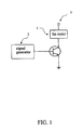
- FIG. 1 shows a control circuit diagram of a signal generator according to a first embodiment of the present invention
- FIG. 2 shows a wave diagram of output signal of the signal generator of the present invention
- FIG. 3 shows a control circuit diagram according to a second embodiment of the present invention
- FIG. 4 shows a wave diagram of voltage, armature current and speed according to the second embodiment of the present invention
- FIG. 5 shows a control circuit diagram according to a third embodiment of the present invention.
- FIG. 6 shows a diagram of basic DC converter and corresponding DC motor terminal voltage of the present invention
- FIG. 7 shows output wave diagrams of a conventional signal generator
- FIG. 8 shows output wave diagrams of a conventional signal generator.
- FIG. 1 and FIG. 2 respectively show a control circuit diagram of a signal generator according to a first embodiment of the present invention and a wave diagram of output signal of the signal generator of the present invention.
- the present invention provides a fan driving circuit using a PWM signal.
- a signal generator generates a control signal at a buffer period when the fan motor changes phase for controlling phase change. Therefore, when phase changes, by means of the control signal at a buffer period, power-consuming would be reduced.
- the fan motor can change phase successfully and operate efficiently for power-saving, capacity-improving and cost-reducing.
- the signal generator 2 mentioned above electronically connects to a fan motor 1 and provides power 3 for the fan motor 1 .
- the signal generator 2 generates a control signal for controlling ON/OFF of the power 3 .
- the signal generator is a fan driving circuit using a PWM signal.
- the signal generator 2 generates a control signal at a buffer period A when the fan motor 1 changes phase (as shown in FIG. 2, between two output pulse waves).
- the control signal at a buffer period A generated by the signal generator 2 , the signal generator 2 would be able to control the phase change of the fan motor 1 .
- the control signal at the buffer period A of the signal generator 2 has a ratio of wave-width within a range of 5% to 30%.
- a novel fan driving circuit using a PWN signal when the fan motor 1 changes phase, by means of the control signal at the buffer period A, power-consuming would be reduced.
- the fan motor 1 can change phase successfully and operate efficiently for power-saving, capacity-improving and cost-reducing.
- FIG. 3 and FIG. 4 respectively show a control circuit diagram according to a second embodiment of the present invention and a wave diagram of voltage, armature current and speed according to the second embodiment of the present invention.
- transistors will have serious power loss problems. Parts of power will be transferred into heat and be depleted. Since the motor 4 is an inductance load, the current passing through the armature will not drop down to zero immediately when the control voltage V i of the transistor becomes zero, resulting from the physical characteristic in which current always changes continually. For example, it will reduce constantly along with a specific time constant.
- the motor 4 will not promptly stop or transiently operate.
- the current of the motor 4 can be controlled by directly adjusting the pulse width of the input control voltage to further dominate operation of the motor 4 .
- the FIG. 4 also shows relation between the duty cycle and speed of the input control pulse. The longer the input voltage pulse is, the faster the operating speed of the motor 4 would be, and vice versa.
- FIG. 5 and FIG. 6 respectively show a control circuit diagram according to a third embodiment of the present invention and a diagram of basic DC converter and corresponding DC motor terminal voltage of the present invention.
- the basic logic structure is: gathering S 1 with S 3 into a group, S 2 with S 4 into another group when switching. The two groups will operate together and become mutual exclusive for preventing occurrence of short circuits. Two rules are described as follows.
- the terminal voltage V m of the motor 5 is equal to +V bb when S 1 , S 3 are ON and S 2 , S 4 are OFF. Meanwhile, the motor 5 operates clock-wise.
- the terminal voltage V m of the motor 5 is equal to ⁇ V bb when S 1 , S 3 are OFF and S 2 , S 4 are ON. Meanwhile, the motor 5 operates underclock-wise.
- the above control rules cooperating with the fan driving circuit using a PWM signal of the present invention can efficiently control the motor.
Abstract
The present invention provides a fan driving circuit using a pulse width modulation (PWM) input signal. Wherein, a signal generator electrically connects to a fan motor and provides power for the fan motor. The signal generator generates a control signal for controlling ON/OFF of the power. Wherein, the signal generator generates a control signal at a buffer period when the fan motor changes phase for controlling phase change. Whereby, by means of the control signal at the buffer period, when phase changes, power-consuming would be reduced. The fan motor can change phase successfully and operate efficiently for power-saving, capacity-improving and cost-reducing.
Description
1. Taiwan Patent No. 507973.
2. U.S. Pat. No. 6,262,549.
3. U.S. Pat. No. 5,942,866.
4. U.S. Pat. No. 5,727,928.
The present invention relates to a fan driving circuit using a Pulse Wide Modulation (PWM) signal. More particularly, by means of a control signal at a buffer period, when phase changes, power-consuming would be reduced. The fan motor can change phase successfully and operate efficiently for power-saving, capacity-improving and cost-reducing.
A control circuit for heat-dissipation system in Taiwan Patent No. 507973 discloses a conventional fan control circuit using a PWM signal. The control circuit includes a signal generator electronically connecting to the heat-dissipation system, providing power of the heat-dissipation system and generating a control signal to control the ON/OFF of the power; and, a power regular apparatus, electronically connecting between the heat-dissipation system and power, paralleling to the signal generator, provides constantly basic power for the circuit of the heat-dissipation system to prevent signals outputting from external devices electronically connecting to the heat-dissipation system from being interfered by the control signal.
Although the fan driving circuit using a PWM signal mentioned above can prevent signals outputting from external devices electronically connecting to the heat-dissipation system from being interfered by the control signal, it is insufficient for the control circuit in real practice. Fan motor must change phase first when operating. The output wave diagrams of phase change when fan motor uses the above control circuit or other conventional control circuits are shown in FIG. 7 and FIG. 8. As shown in the above diagrams, the waves when the fan motor changes phase is successive. Therefore, conventional fan driving circuit using a PWM signal tends to power-consuming increasing by fan motor changing phase. Since the required power for the fan increases, it is impossible to save power and operate the fan efficiently. That is, when changes phase, the fan motor is unable to change phase successfully, resulting in low efficiency.
The main objective of the present invention is that when phase changes, by means of a control signal at a buffer period, power-consuming would be reduced. The fan motor can change phase successfully and operate efficiently for power-saving, capacity-improving and cost-reducing.
To achieve the above objective, the present invention provides a fan driving circuit using a pulse width modulation (PWM) signal. Wherein, a signal generator electronically connects to a fan motor and provides power for the fan motor. The signal generator generates a control signal for controlling ON/OFF of the power. Wherein, the signal generator generates a control signal at a buffer period when the fan motor changes phase for controlling phase change. Therefore, when phase changes, by means of a control signal at a buffer period, power-consuming would be reduced. The fan motor can change phase successfully and operate efficiently for power-saving, capacity-improving and cost-reducing.
The present invention will be better understood from the following detailed description of preferred embodiments of the invention, take in conjunction with the accompanying drawings, in which:
FIG. 1 shows a control circuit diagram of a signal generator according to a first embodiment of the present invention;
FIG. 2 shows a wave diagram of output signal of the signal generator of the present invention;
FIG. 3 shows a control circuit diagram according to a second embodiment of the present invention;
FIG. 4 shows a wave diagram of voltage, armature current and speed according to the second embodiment of the present invention;
FIG. 5 shows a control circuit diagram according to a third embodiment of the present invention;
FIG. 6 shows a diagram of basic DC converter and corresponding DC motor terminal voltage of the present invention;
FIG. 7 shows output wave diagrams of a conventional signal generator; and
FIG. 8 shows output wave diagrams of a conventional signal generator.
The following descriptions of the preferred embodiments are provided to understand th features and the structures of the present invention.
FIG. 1 and FIG. 2 respectively show a control circuit diagram of a signal generator according to a first embodiment of the present invention and a wave diagram of output signal of the signal generator of the present invention. As shown in the diagrams, the present invention provides a fan driving circuit using a PWM signal. Wherein, a signal generator generates a control signal at a buffer period when the fan motor changes phase for controlling phase change. Therefore, when phase changes, by means of the control signal at a buffer period, power-consuming would be reduced. The fan motor can change phase successfully and operate efficiently for power-saving, capacity-improving and cost-reducing.
The signal generator 2 mentioned above electronically connects to a fan motor 1 and provides power 3 for the fan motor 1. Wherein, the signal generator 2 generates a control signal for controlling ON/OFF of the power 3. Moreover, the signal generator is a fan driving circuit using a PWM signal. The signal generator 2 generates a control signal at a buffer period A when the fan motor 1 changes phase (as shown in FIG. 2, between two output pulse waves). By the control signal at a buffer period A, generated by the signal generator 2, the signal generator 2 would be able to control the phase change of the fan motor 1. The control signal at the buffer period A of the signal generator 2 has a ratio of wave-width within a range of 5% to 30%. According to the invention described above, a novel fan driving circuit using a PWN signal, when the fan motor 1 changes phase, by means of the control signal at the buffer period A, power-consuming would be reduced. The fan motor 1 can change phase successfully and operate efficiently for power-saving, capacity-improving and cost-reducing.
FIG. 3 and FIG. 4 respectively show a control circuit diagram according to a second embodiment of the present invention and a wave diagram of voltage, armature current and speed according to the second embodiment of the present invention. As shown in the diagrams, under larger load, transistors will have serious power loss problems. Parts of power will be transferred into heat and be depleted. Since the motor 4 is an inductance load, the current passing through the armature will not drop down to zero immediately when the control voltage Vi of the transistor becomes zero, resulting from the physical characteristic in which current always changes continually. For example, it will reduce constantly along with a specific time constant. Similarly, when Vi suddenly increases, Ia will rise constantly along with a specific time constant, therefore, by inertia of the motor, the motor 4 will not promptly stop or transiently operate. As shown in FIG. 4, the current of the motor 4 can be controlled by directly adjusting the pulse width of the input control voltage to further dominate operation of the motor 4. In addition, the FIG. 4 also shows relation between the duty cycle and speed of the input control pulse. The longer the input voltage pulse is, the faster the operating speed of the motor 4 would be, and vice versa.
FIG. 5 and FIG. 6 respectively show a control circuit diagram according to a third embodiment of the present invention and a diagram of basic DC converter and corresponding DC motor terminal voltage of the present invention. As shown in the diagrams, to solve the shortcomings of using a relay to control trend, in the third embodiment of the present invention, the basic logic structure is: gathering S1 with S3 into a group, S2 with S4 into another group when switching. The two groups will operate together and become mutual exclusive for preventing occurrence of short circuits. Two rules are described as follows.
(1) The terminal voltage Vm of the motor 5 is equal to +Vbb when S1, S3 are ON and S2, S4 are OFF. Meanwhile, the motor 5 operates clock-wise.
(2) The terminal voltage Vm of the motor 5 is equal to −Vbb when S1, S3 are OFF and S2, S4 are ON. Meanwhile, the motor 5 operates underclock-wise.
The above control rules cooperating with the fan driving circuit using a PWM signal of the present invention can efficiently control the motor.
In summation of the foregoing section, the invention herein fully complies will all new patent application requirement and is hereby submitted to the patent bureau for review and the granting of the commensurate patent rights. The present invention may be embodied in other specific forms without departing from the spirit of the attributes thereof; therefore, the illustrated embodiment should be considered in all aspects as illustrative and not restrictive, reference being made to the appended claims rather than to the foregoing description to indicate the scope of the invention.
Claims (1)
1. A fan driving circuit using a PWM input signal for a signal generator electronically connecting to a fan motor and providing power for said fan motor, said signal generator generating a control signal for controlling ON/OFF of said power; which is characterized in that:
said signal generator being a PWM circuit, generating a control signal at a buffer period when said fan motor changing phase for controlling phase change; wherein said buffer period has a ratio wave-width within a range from 5% to 30%.
Applications Claiming Priority (2)
| Application Number | Priority Date | Filing Date | Title |
|---|---|---|---|
| TW092103960 | 2003-02-25 | ||
| TW092103960A TW591873B (en) | 2003-02-25 | 2003-02-25 | Fan driving circuit using a PWM input signal |
Publications (2)
| Publication Number | Publication Date |
|---|---|
| US20040164699A1 US20040164699A1 (en) | 2004-08-26 |
| US6806673B2 true US6806673B2 (en) | 2004-10-19 |
Family
ID=32867355
Family Applications (1)
| Application Number | Title | Priority Date | Filing Date |
|---|---|---|---|
| US10/609,581 Expired - Lifetime US6806673B2 (en) | 2003-02-25 | 2003-07-01 | Fan driving circuit using a PWM input signal |
Country Status (2)
| Country | Link |
|---|---|
| US (1) | US6806673B2 (en) |
| TW (1) | TW591873B (en) |
Cited By (18)
| Publication number | Priority date | Publication date | Assignee | Title |
|---|---|---|---|---|
| US20040164773A1 (en) * | 2003-02-25 | 2004-08-26 | Datech Technology Co., Ltd. | Fan driving circuit using an adaptive PWM input signal |
| US20050002657A1 (en) * | 2003-07-04 | 2005-01-06 | Wu Chia-Feng | Fan speed control circuit |
| US20050105897A1 (en) * | 2003-11-19 | 2005-05-19 | Wu Chia-Feng | Motor control circuit |
| US20060056823A1 (en) * | 2003-07-04 | 2006-03-16 | Delta Electronics, Inc. | Fan speed control circuit |
| US7132809B1 (en) * | 2005-11-09 | 2006-11-07 | Inventec Corporation | Fan-controlling system to control a plurality of fans with different pulse width modulation signals |
| US7479753B1 (en) * | 2004-02-24 | 2009-01-20 | Nvidia Corporation | Fan speed controller |
| US20090099792A1 (en) * | 2007-10-12 | 2009-04-16 | Dell Products L.P. | System and Method for Increasing the Power Efficiency of Cooling Fans |
| US20090121692A1 (en) * | 2007-11-08 | 2009-05-14 | Ching-Sheng Li | Vibration-Reduction Fan Driving Circuit |
| US7849332B1 (en) | 2002-11-14 | 2010-12-07 | Nvidia Corporation | Processor voltage adjustment system and method |
| US7882369B1 (en) | 2002-11-14 | 2011-02-01 | Nvidia Corporation | Processor performance adjustment system and method |
| US7886164B1 (en) | 2002-11-14 | 2011-02-08 | Nvidia Corporation | Processor temperature adjustment system and method |
| US8370663B2 (en) | 2008-02-11 | 2013-02-05 | Nvidia Corporation | Power management with dynamic frequency adjustments |
| US8839006B2 (en) | 2010-05-28 | 2014-09-16 | Nvidia Corporation | Power consumption reduction systems and methods |
| US9091273B2 (en) * | 2013-11-28 | 2015-07-28 | Inventec (Pudong) Technology Corporation | Controlling circuit for outputting a square wave signal to control a fan rotating speed |
| US9134782B2 (en) | 2007-05-07 | 2015-09-15 | Nvidia Corporation | Maintaining optimum voltage supply to match performance of an integrated circuit |
| US9256265B2 (en) | 2009-12-30 | 2016-02-09 | Nvidia Corporation | Method and system for artificially and dynamically limiting the framerate of a graphics processing unit |
| US9348395B2 (en) | 2012-10-15 | 2016-05-24 | Dell Products L.P. | Power demand reduction system |
| US9830889B2 (en) | 2009-12-31 | 2017-11-28 | Nvidia Corporation | Methods and system for artifically and dynamically limiting the display resolution of an application |
Families Citing this family (1)
| Publication number | Priority date | Publication date | Assignee | Title |
|---|---|---|---|---|
| TWI473415B (en) * | 2012-04-10 | 2015-02-11 | Padauk Technology Co Ltd | Controller and method for improving motor driving efficiency |
Citations (6)
| Publication number | Priority date | Publication date | Assignee | Title |
|---|---|---|---|---|
| US5099408A (en) * | 1989-05-23 | 1992-03-24 | Kasuga Denki Kabushiki Kaisha | System for controlling a PWM inverter having delay time compensation |
| US5727928A (en) | 1995-12-14 | 1998-03-17 | Dell Usa L.P. | Fan speed monitoring system for determining the speed of a PWM fan |
| US5942866A (en) * | 1998-01-16 | 1999-08-24 | Hsieh; Hsin-Mao | PWM control circuit for a DC brushless fan |
| US6091216A (en) * | 1998-05-28 | 2000-07-18 | Ibiden Co., Ltd. | Motor-driving circuit |
| US6262549B1 (en) | 2000-06-29 | 2001-07-17 | System General Corp. | Fan speed pulse filter for a PWM fan |
| US20030053323A1 (en) * | 2001-09-20 | 2003-03-20 | Tomonori Kimura | Power inverter designed to minimize switching loss |
-
2003
- 2003-02-25 TW TW092103960A patent/TW591873B/en not_active IP Right Cessation
- 2003-07-01 US US10/609,581 patent/US6806673B2/en not_active Expired - Lifetime
Patent Citations (6)
| Publication number | Priority date | Publication date | Assignee | Title |
|---|---|---|---|---|
| US5099408A (en) * | 1989-05-23 | 1992-03-24 | Kasuga Denki Kabushiki Kaisha | System for controlling a PWM inverter having delay time compensation |
| US5727928A (en) | 1995-12-14 | 1998-03-17 | Dell Usa L.P. | Fan speed monitoring system for determining the speed of a PWM fan |
| US5942866A (en) * | 1998-01-16 | 1999-08-24 | Hsieh; Hsin-Mao | PWM control circuit for a DC brushless fan |
| US6091216A (en) * | 1998-05-28 | 2000-07-18 | Ibiden Co., Ltd. | Motor-driving circuit |
| US6262549B1 (en) | 2000-06-29 | 2001-07-17 | System General Corp. | Fan speed pulse filter for a PWM fan |
| US20030053323A1 (en) * | 2001-09-20 | 2003-03-20 | Tomonori Kimura | Power inverter designed to minimize switching loss |
Cited By (25)
| Publication number | Priority date | Publication date | Assignee | Title |
|---|---|---|---|---|
| US7886164B1 (en) | 2002-11-14 | 2011-02-08 | Nvidia Corporation | Processor temperature adjustment system and method |
| US7882369B1 (en) | 2002-11-14 | 2011-02-01 | Nvidia Corporation | Processor performance adjustment system and method |
| US7849332B1 (en) | 2002-11-14 | 2010-12-07 | Nvidia Corporation | Processor voltage adjustment system and method |
| US20040164773A1 (en) * | 2003-02-25 | 2004-08-26 | Datech Technology Co., Ltd. | Fan driving circuit using an adaptive PWM input signal |
| US20050002657A1 (en) * | 2003-07-04 | 2005-01-06 | Wu Chia-Feng | Fan speed control circuit |
| US20060056823A1 (en) * | 2003-07-04 | 2006-03-16 | Delta Electronics, Inc. | Fan speed control circuit |
| US7218846B2 (en) * | 2003-07-04 | 2007-05-15 | Delta Electronics, Inc. | Fan speed control circuit |
| US7233121B2 (en) * | 2003-07-04 | 2007-06-19 | Delta Electronics, Inc. | Fan speed control circuit |
| US7567749B2 (en) | 2003-11-19 | 2009-07-28 | Delta Electronics, Inc. | Motor control circuit |
| US20050105897A1 (en) * | 2003-11-19 | 2005-05-19 | Wu Chia-Feng | Motor control circuit |
| US20070160354A1 (en) * | 2003-11-19 | 2007-07-12 | Wu Chia-Feng | Motor control circuit |
| US7242857B2 (en) * | 2003-11-19 | 2007-07-10 | Delta Electronics, Inc. | Motor control circuit |
| US7479753B1 (en) * | 2004-02-24 | 2009-01-20 | Nvidia Corporation | Fan speed controller |
| US7132809B1 (en) * | 2005-11-09 | 2006-11-07 | Inventec Corporation | Fan-controlling system to control a plurality of fans with different pulse width modulation signals |
| US9134782B2 (en) | 2007-05-07 | 2015-09-15 | Nvidia Corporation | Maintaining optimum voltage supply to match performance of an integrated circuit |
| US8370000B2 (en) | 2007-10-12 | 2013-02-05 | Dell Products L.P. | System and method for increasing the power efficiency of cooling fans |
| US20090099792A1 (en) * | 2007-10-12 | 2009-04-16 | Dell Products L.P. | System and Method for Increasing the Power Efficiency of Cooling Fans |
| US20090121692A1 (en) * | 2007-11-08 | 2009-05-14 | Ching-Sheng Li | Vibration-Reduction Fan Driving Circuit |
| US8370663B2 (en) | 2008-02-11 | 2013-02-05 | Nvidia Corporation | Power management with dynamic frequency adjustments |
| US8775843B2 (en) | 2008-02-11 | 2014-07-08 | Nvidia Corporation | Power management with dynamic frequency adjustments |
| US9256265B2 (en) | 2009-12-30 | 2016-02-09 | Nvidia Corporation | Method and system for artificially and dynamically limiting the framerate of a graphics processing unit |
| US9830889B2 (en) | 2009-12-31 | 2017-11-28 | Nvidia Corporation | Methods and system for artifically and dynamically limiting the display resolution of an application |
| US8839006B2 (en) | 2010-05-28 | 2014-09-16 | Nvidia Corporation | Power consumption reduction systems and methods |
| US9348395B2 (en) | 2012-10-15 | 2016-05-24 | Dell Products L.P. | Power demand reduction system |
| US9091273B2 (en) * | 2013-11-28 | 2015-07-28 | Inventec (Pudong) Technology Corporation | Controlling circuit for outputting a square wave signal to control a fan rotating speed |
Also Published As
| Publication number | Publication date |
|---|---|
| TW200417125A (en) | 2004-09-01 |
| US20040164699A1 (en) | 2004-08-26 |
| TW591873B (en) | 2004-06-11 |
Similar Documents
| Publication | Publication Date | Title |
|---|---|---|
| US6806673B2 (en) | Fan driving circuit using a PWM input signal | |
| US5705919A (en) | Low drop-out switching regulator architecture | |
| US7285941B2 (en) | DC-DC converter with load intensity control method | |
| EP1961118B1 (en) | High voltage power switches using low voltage transistors | |
| JPH11220875A (en) | Controller circuit for controlling step-down switching regulator operating in intermittent conduction mode | |
| KR20010014757A (en) | Multiple output buck converter with single inductor | |
| JP2008072872A (en) | Switching regulator | |
| JPH06169592A (en) | Electric-current control circuit of inductive load | |
| US11522459B2 (en) | Combining temperature monitoring and true different current sensing in a multiphase voltage regulator | |
| JP4302675B2 (en) | Fan motor rotation speed control circuit and voltage regulation module thereof | |
| US20210067042A1 (en) | Multi-phase switched capacitor power converter and control method thereof | |
| US9071138B2 (en) | Adaptive digital pulse width modulation generator for buck converters | |
| US20040164773A1 (en) | Fan driving circuit using an adaptive PWM input signal | |
| EP2132869B1 (en) | Brushed motor control with voltage boost for reverse and braking | |
| US9184684B2 (en) | Motor driving circuit and method thereof | |
| JP4860998B2 (en) | Motor drive circuit, method and cooling device using the same | |
| TW201233015A (en) | Power converter and gate driver of power transistor thereof | |
| JP2009136045A (en) | Switching regulator and its control circuit | |
| JP2006238603A (en) | Switching regulator | |
| TW201729525A (en) | Switching regulator | |
| TW201406046A (en) | Driving circuit and method for fan | |
| WO2012083710A1 (en) | Partitioned power tube circuit and method for implementing same | |
| CN110663164B (en) | Power converter pre-driver system with multiple power modes | |
| JP3940137B2 (en) | Differential load drive circuit | |
| US20140028232A1 (en) | Motor Driving Circuit and Method |
Legal Events
| Date | Code | Title | Description |
|---|---|---|---|
| AS | Assignment |
Owner name: DATECH TECHNOLOGY CO., LTD., TAIWAN Free format text: ASSIGNMENT OF ASSIGNORS INTEREST;ASSIGNOR:HO, TSUNG-TE;REEL/FRAME:014254/0562 Effective date: 20030128 |
|
| STCF | Information on status: patent grant |
Free format text: PATENTED CASE |
|
| FPAY | Fee payment |
Year of fee payment: 4 |
|
| REMI | Maintenance fee reminder mailed | ||
| FPAY | Fee payment |
Year of fee payment: 8 |
|
| FPAY | Fee payment |
Year of fee payment: 12 |