US6814700B1 - Soft tissue retractor and method for providing surgical access - Google Patents
Soft tissue retractor and method for providing surgical access Download PDFInfo
- Publication number
- US6814700B1 US6814700B1 US09/527,485 US52748500A US6814700B1 US 6814700 B1 US6814700 B1 US 6814700B1 US 52748500 A US52748500 A US 52748500A US 6814700 B1 US6814700 B1 US 6814700B1
- Authority
- US
- United States
- Prior art keywords
- retractor
- body cavity
- passage
- frame
- anchoring frame
- Prior art date
- Legal status (The legal status is an assumption and is not a legal conclusion. Google has not performed a legal analysis and makes no representation as to the accuracy of the status listed.)
- Expired - Fee Related
Links
Images


Classifications
-
- A—HUMAN NECESSITIES
- A61—MEDICAL OR VETERINARY SCIENCE; HYGIENE
- A61B—DIAGNOSIS; SURGERY; IDENTIFICATION
- A61B17/00—Surgical instruments, devices or methods, e.g. tourniquets
- A61B17/02—Surgical instruments, devices or methods, e.g. tourniquets for holding wounds open; Tractors
- A61B17/0293—Surgical instruments, devices or methods, e.g. tourniquets for holding wounds open; Tractors with ring member to support retractor elements
-
- A—HUMAN NECESSITIES
- A61—MEDICAL OR VETERINARY SCIENCE; HYGIENE
- A61B—DIAGNOSIS; SURGERY; IDENTIFICATION
- A61B17/00—Surgical instruments, devices or methods, e.g. tourniquets
- A61B17/34—Trocars; Puncturing needles
- A61B17/3417—Details of tips or shafts, e.g. grooves, expandable, bendable; Multiple coaxial sliding cannulas, e.g. for dilating
- A61B17/3421—Cannulas
- A61B17/3423—Access ports, e.g. toroid shape introducers for instruments or hands
-
- A—HUMAN NECESSITIES
- A61—MEDICAL OR VETERINARY SCIENCE; HYGIENE
- A61B—DIAGNOSIS; SURGERY; IDENTIFICATION
- A61B17/00—Surgical instruments, devices or methods, e.g. tourniquets
- A61B17/34—Trocars; Puncturing needles
- A61B17/3468—Trocars; Puncturing needles for implanting or removing devices, e.g. prostheses, implants, seeds, wires
-
- A—HUMAN NECESSITIES
- A61—MEDICAL OR VETERINARY SCIENCE; HYGIENE
- A61B—DIAGNOSIS; SURGERY; IDENTIFICATION
- A61B17/00—Surgical instruments, devices or methods, e.g. tourniquets
- A61B17/02—Surgical instruments, devices or methods, e.g. tourniquets for holding wounds open; Tractors
-
- A—HUMAN NECESSITIES
- A61—MEDICAL OR VETERINARY SCIENCE; HYGIENE
- A61B—DIAGNOSIS; SURGERY; IDENTIFICATION
- A61B17/00—Surgical instruments, devices or methods, e.g. tourniquets
- A61B17/02—Surgical instruments, devices or methods, e.g. tourniquets for holding wounds open; Tractors
- A61B17/0206—Surgical instruments, devices or methods, e.g. tourniquets for holding wounds open; Tractors with antagonistic arms as supports for retractor elements
-
- A—HUMAN NECESSITIES
- A61—MEDICAL OR VETERINARY SCIENCE; HYGIENE
- A61B—DIAGNOSIS; SURGERY; IDENTIFICATION
- A61B17/00—Surgical instruments, devices or methods, e.g. tourniquets
- A61B17/02—Surgical instruments, devices or methods, e.g. tourniquets for holding wounds open; Tractors
- A61B17/025—Joint distractors
-
- A—HUMAN NECESSITIES
- A61—MEDICAL OR VETERINARY SCIENCE; HYGIENE
- A61B—DIAGNOSIS; SURGERY; IDENTIFICATION
- A61B17/00—Surgical instruments, devices or methods, e.g. tourniquets
- A61B17/34—Trocars; Puncturing needles
- A61B17/3417—Details of tips or shafts, e.g. grooves, expandable, bendable; Multiple coaxial sliding cannulas, e.g. for dilating
- A61B17/3421—Cannulas
- A61B17/3431—Cannulas being collapsible, e.g. made of thin flexible material
-
- A—HUMAN NECESSITIES
- A61—MEDICAL OR VETERINARY SCIENCE; HYGIENE
- A61B—DIAGNOSIS; SURGERY; IDENTIFICATION
- A61B17/00—Surgical instruments, devices or methods, e.g. tourniquets
- A61B17/00234—Surgical instruments, devices or methods, e.g. tourniquets for minimally invasive surgery
- A61B2017/00238—Type of minimally invasive operation
- A61B2017/00243—Type of minimally invasive operation cardiac
-
- A—HUMAN NECESSITIES
- A61—MEDICAL OR VETERINARY SCIENCE; HYGIENE
- A61B—DIAGNOSIS; SURGERY; IDENTIFICATION
- A61B17/00—Surgical instruments, devices or methods, e.g. tourniquets
- A61B17/34—Trocars; Puncturing needles
- A61B2017/348—Means for supporting the trocar against the body or retaining the trocar inside the body
- A61B2017/3482—Means for supporting the trocar against the body or retaining the trocar inside the body inside
-
- A—HUMAN NECESSITIES
- A61—MEDICAL OR VETERINARY SCIENCE; HYGIENE
- A61B—DIAGNOSIS; SURGERY; IDENTIFICATION
- A61B90/00—Instruments, implements or accessories specially adapted for surgery or diagnosis and not covered by any of the groups A61B1/00 - A61B50/00, e.g. for luxation treatment or for protecting wound edges
- A61B90/30—Devices for illuminating a surgical field, the devices having an interrelation with other surgical devices or with a surgical procedure
- A61B2090/306—Devices for illuminating a surgical field, the devices having an interrelation with other surgical devices or with a surgical procedure using optical fibres
Definitions
- the present invention relates generally to minimally invasive and less invasive surgical access. More particularly, the present invention provides retractors for soft tissues and methods for their use to provide surgical access into body cavities.
- Coronary artery disease remains the leading cause of morbidity and mortality in western societies. Coronary artery disease is manifested in a number of ways. For example, disease of the coronary arteries can lead to insufficient blood flow resulting in the discomfort and risks of angina and ischemia. In severe cases, acute blockage of coronary blood flow can result in myocardial infarction, leading to immediate death or damage to the myocardial tissue.
- a number of approaches have been developed for treating coronary artery disease. In less severe cases, it is often sufficient to treat the symptoms with pharmaceuticals and lifestyle modification to lessen the underlying causes of disease. In more severe cases, the coronary blockage can often be treated endovascularly using techniques such as balloon angioplasty, atherectomy, or stents.
- a source of arterial blood is then connected to a coronary artery downstream from an occlusion, while the patient's heart is maintained under cardioplegia and circulation is supported by cardiopulmonary bypass.
- the source of blood may be a vessel taken from elsewhere in the body such as a saphenous vein or radial artery, or an artery in the chest or abdomen such as the left or right internal mammary artery or the gastroepiploic artery.
- the target coronary artery can be the left anterior descending artery, right coronary artery, circumflex artery, or any other coronary artery which might be narrowed or occluded.
- trocar sheaths have not been optimally adapted for performing thoracoscopic coronary artery bypass.
- the length of conventional trocar sheaths and the small size of their lumens limits the maneuverability of surgical instruments and inhibits the ability to look directly into the chest cavity while an instrument is positioned through the trocar sheath.
- U.S. Pat. No. 5,391,156 describes a flexible endoscopic surgical port having a tubular body, the outer end of which is optionally divisible into a plurality of flaps, thereby matching the length of the tubular body with the thickness of a body wall.
- a retainer ring engages the flaps to hold the port axially, while the hoop strength of the tubular body holds the adjacent tissue in a retracted position.
- U.S. Pat. No. 4,274,398 describes a surgical retractor having elastic tubes which hold hooks under radial tension from a notched frame.
- U.S. Pat. Nos. 4,430,991, and 4,434,791 describe similar surgical retractor frames for use with hooked members. Such a system is commercially available under the trade name LoneStar Retractor SystemTM.
- a surgical drape having a central open ring for insertion over known surgical retractors is commercially available from Becton Dickinson of Franklin Lakes, N.J. under the tradename Vidrape®. Relevant minimally invasive methods and devices for heart surgery are described in U.S. Pat. No. 5,452,733; U.S. Pat. No. 5,571,215; U.S. Pat. No. 5,501,698; U.S. Pat. No. 5,588,949; and U.S. Pat. No. 5,799,661, the full disclosures of which are incorporated herein by reference.
- the present invention provides a retractor for providing surgical access to a body cavity of a patient through a passage in tissue.
- the retractor comprises an anchoring frame having an upper surface, a lower surface, and an opening therethrough which defines an axial axis.
- the anchoring frame is positionable through the passage into the body cavity.
- a flexible tensioning member is attached to the anchoring frame and extendable from the frame out of the body through the passage.
- the tensioning member is selectively tensionable to spread the tissue radially outwardly from the axial axis.
- an attachment mechanism on the tensioning member maintains tension so as to retract tissue from the passage.
- the tensioning member need only be capable of withstanding and transferring the tension imposed by the attachment mechanism, there being no need for a rigid structure having sufficient hoop strength to maintain the tissue in the retracted position.
- the resulting surgical access window need not be compromised by any rigid lumen wall or rigid blade-type structure, and the retraction load is distributed atraumatically over a wide area of the tissue by the flexible tensioning member.
- the anchoring frame will have a narrow profile configuration for insertion through an incision into the body cavity, and will be expandable to a wide profile configuration once inside the body cavity.
- the frame may comprise a variety of collapsible and expandable structures, including a ring of resilient material which expands to the large configuration when released.
- the tensioning member is preferably formed of a plurality of elongate tabs or strips of cloth, tape, cord, or strap material, ideally comprising an absorbent material such as gauze so as to absorb any fluids released by the tissue bordering the passage.
- an elastomeric or semi-elastomeric sheet or strip may be used.
- the present invention provides a retractor for providing surgical access into a chest cavity defined by a plurality of ribs.
- the ribs are separated by intercostal tissue and an intercostal width.
- the retractor comprises an anchoring frame which is insertable into the chest cavity through a passage between two ribs, the frame having an opening.
- a flexible tensioning member extends from at least two opposing sides of the opening in the frame. The tensioning member is able to extend out of the chest cavity through the passage when the frame is within the chest cavity and the opening in the frame is generally aligned with the passage.
- the tensioning member may be tensioned to spread the intercostal tissue outward toward the two ribs.
- Such a retractor is particularly well suited for forming an anterior mediastinotomy or small thoracotomy for use in a less invasive coronary artery bypass grafting procedure or other cardiac procedure.
- an attachment mechanism on the tensioning member maintains outward radial tension from outside the patient to hold the intercostal tissue in a retracted position.
- the attachment mechanism comprises an adhesive disposed on the tensioning member to facilitate attachment to an outer surface of the patient's chest.
- a surgical film may be adhered to the exterior of the chest surrounding the passage to facilitate adherence of the tensioning member to the chest wall.
- the attachment mechanism comprises a plurality of clasps or other coupling devices disposed about an outer ring structure which is positioned outside the body cavity.
- the present invention provides an illuminated retractor for providing surgical access to a body cavity of a patient through a passage in tissue.
- the retractor comprises an internal anchor having an opening, the anchor being insertable through the passage and into the body cavity.
- a tissue restraining structure extends proximally from the internal anchor for holding the passage open sufficiently to provide direct visualization of the internal body cavity from outside the patient.
- an external anchor is spaced proximally from the internal anchor on the tissue restraining member.
- An illuminating device is disposed adjacent to the opening in the internal anchor to facilitate visualization of the cavity through the open passage.
- the present invention provides a tissue retractor system for providing surgical access through an incision in tissue to a body cavity of a patient.
- the system generally comprises a retractor and a retractor delivery device.
- the retractor comprises an anchoring frame having an opening, wherein the frame is restrainable into a narrow profile to facilitate insertion of the frame into the body cavity.
- the frame is expandable into a wide profile when inside the body cavity.
- a flexible tensioning member extends from the frame adjacent to the opening and is selectively tensionable to retract the tissue adjacent the incision, and is adapted to be secured in tension outside the body cavity.
- the retractor delivery device comprises a device body having distal and proximal ends, and a pair of inward facing surfaces near the distal end which restrain a frame of the retractor therebetween to a small profile.
- a handle supports the inward facing surfaces from a proximal end.
- An actuator may be provided on the handle to effect expansion of the frame within the body cavity.
- the present invention also provides a method for retracting tissue to temporarily widen a penetration into a body cavity, the method comprising positioning an anchoring frame against a tissue surface within the body cavity adjacent to the penetration so that an opening in the frame is aligned with the penetration.
- the frame has a width across the opening which is wider than the penetration.
- a tissue restraining member extending from the frame out of the body cavity through the penetration is tensioned so as to urge the tissue adjacent the penetration outwardly.
- the present invention provides a method for performing surgery on a patient's heart, the heart being disposed within a chest cavity defined by a plurality of ribs, the ribs being separated by intercostal tissue and an intercostal width.
- the method comprises inserting an anchoring frame into the chest cavity through an incision between two ribs, wherein the frame has an opening and a width across the opening wider than the intercostal width. Tension is then imposed on a plurality of flexible tabs extending from the frame adjacent to the opening so as to widen the incision. Surgery is then performed on the heart using instruments positioned through the widened incision.
- FIG. 1 shows a retractor system according to the principles of the present invention, the system including a retractor and an associated delivery device.
- FIG. 2 is a cutaway view of the retractor of FIG. 1 as used for retracting intercostal tissue from between ribs to provide access to the chest cavity.
- FIG. 2A is a cutaway view of a surgical instrument positioned through a typical known trocar sheath.
- FIG. 2B is a cutaway view of a surgical instrument positioned through the retractor of FIG. 1, showing the increased angulation and maneuverability provided by the surgical access of the present invention.
- FIG. 3 shows the retractor system of FIG. 1 with the retractor restrained in a small configuration by the delivery device.
- FIGS. 4, 4 A, 5 and 6 illustrate a method of using the retractor system of FIG. 1 to provide surgical access to a body cavity.
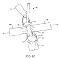
- FIGS. 6A-6C illustrate alternative delivery devices for use with the retractor of FIG. 1 .
- FIGS. 6D-G illustrate an alternative retractor having grommets and an associated delivery device, according to the principles of the present invention.
- FIGS. 7-9A show alternative embodiments of tissue retractors according to the principles of the present invention.
- FIGS. 10A-10E illustrate an alternative embodiment of a retractor system according to the principles of the present invention and a method for its use.
- FIG. 10F illustrates an alternative outer ring structure for use with the retractor of FIG. 10 A.
- FIGS. 11A and 11B illustrate a retractor having illuminating fiberoptics disposed about an internal anchoring ring to provide both illumination and access to an internal body cavity, according to the principles of the present invention.
- FIGS. 12A and 12B illustrate a method for using the retractor of FIG. 1 for coronary artery bypass grafting, according to the principles of the present invention.
- FIG. 13 illustrates a method of retracting tissue during treatment of cardiac valve disease, according to the principles of the present invention.
- the devices and methods of the present invention are suitable for providing access for a variety of surgical procedures within the cavities of the body. Such access is particularly advantageous during minimally invasive and less invasive surgical procedures in which surgical instruments are introduced through an access window provided by the retraction of tissue.
- the present retraction methods and devices will find particular use where direct visualization into a body cavity through a percutaneous penetration facilitates the surgical procedure.
- an endoscope, laparoscope, thoracoscope, or other visualization device may be inserted through such an access window for telescopic or video-based visualization.
- tissues and/or organs may be temporarily extended through the access window to allow external manipulation during therapy.
- the retraction methods and devices of the present invention will thus find applications in providing surgical access to the pelvis, abdomen, thorax, and other body cavities, to facilitate surgical intervention on the gall bladder, colon, reproductive organs, kidneys, liver, stomach, heart, lungs, and other body structures.
- the present invention will find its most immediate application in less invasive surgery of the heart, particularly in less-invasive coronary artery bypass grafting, less-invasive valve repair and replacement, and other cardiac procedures.
- Surgical access windows provided by the flexible tensioning member of the retractor of the present invention will easily flex to adapt to the minimally invasive tools used in less invasive bypass procedures, thereby allowing these tools to be manipulated more easily and used at a wider range of angles than could be accommodated by the rigid and semi-rigid trocar sheaths and conventional rigid retractors of the prior art.
- tension in a flexible strap or tab the intercostal tissue between ribs may be atraumatically retracted as widely as possible without inflicting a gross displacement of the ribs and the resulting patient trauma.
- the retraction methods and devices of the present invention may also be used in combination with the excision of costal cartilage or even a partial sternotomy or small thoracotomy to maximize the size of the open access port.
- a retraction system 10 comprises a retractor 12 and a delivery device 14 .
- Retractor 12 includes an anchor ring 16 from which a plurality of flexible tabs 18 extend.
- An adhesive is coated over a portion of each of tabs 18 , and a backing strip 20 removably covers the adhesive to facilitate handling the retractor.
- Anchoring ring 16 may be either rigid or flexible, but preferably comprises a resilient material biased to form an annular ring shape.
- a variety of other frame shapes might also be used, including C-shaped, U-shaped, rectangular, elliptical, triangular, parabolic, and optionally including articulated or living hinge joints.
- the anchoring frame will have at least two sections separated by an opening or gap such that the frame may be placed through a passage in a body wall into a body cavity and the two sections positioned on either side of the passage with the opening therebetween aligned with the passage.
- the anchoring ring may optionally be made of a relatively high strength polymer such as DelrinTM, nylon, high density polyethylene, and the like.
- the anchoring ring comprises a high strength biocompatible alloy, ideally being a superelastic alloy such as Nitinol®.
- a superelastic alloy such as Nitinol®.
- Such an alloy ring may be formed by welding, crimping the joint with a stainless steel tube, butt jointing with heat shrink tubing, or the like, the ring preferably having a diameter between about 10 mm and 9 cm.
- the exemplary annular superelastic alloy anchoring ring may be readily compressed to a small configuration for insertion, will readily expand to the large open configuration shown in FIGS. 1-2 once inside the body cavity, and will withstand the compressive loads imposed by flexible tabs 18 during retraction of tissue as described hereinbelow.
- the axial dimension of anchoring ring 16 is preferably minimized to provide maximum open working area within the body cavity and to provide maximum maneuverability of instruments positioned through it.
- the anchoring ring has an axial thickness of less than about 20 mm, and preferably less than about 10 mm.
- Flexible tabs 18 preferably comprise elongate strips of an absorbent material such as gauze, cloth tape, or the like. Such gauze tabs may be easily looped over anchoring ring 16 and sutured, sewn, adhesively bonded, heat sealed, or welded to themselves. Alternatively, tabs 18 may be directly adhesively bonded to anchoring ring 16 , may be molded into the anchoring ring, or may have the anchoring ring woven into the tab material. Use of an absorbent material allows the flexible tab to absorb blood and other fluids which might otherwise seep from the retracted tissue into the body cavity. Where absorbency is less important, flexible tabs 18 may be an elastomer or a flexible, deformable or resilient metal.
- an absorbent material such as gauze, cloth tape, or the like.
- the adhesive behind backing strips 20 will generally comprise a medical grade adhesive suitable for attachment to human skin or to paper, cloth, metal or plastic surfaces, such as an acrylate or other suitable adhesive. Conveniently, attachment may be facilitated by the use of a plastic film adhered to the patient's chest prior to insertion of the retractor, allowing backing strips 20 to be affixed securely to the plastic film.
- Delivery device 14 generally includes a distal end 22 and a proximal end 24 .
- the distal end includes inward facing surfaces 25 which releasably restrain the anchoring ring in a small profile configuration, while the proximal end 24 includes a handle 27 for manipulation of these inward facing surfaces.
- Handle 27 comprises a pair of finger loops which may be actuated by passing the thumb and a finger therethrough and separating and/or bringing together the thumb and finger.
- Arms 29 extend distally to support each of the inward facing surfaces, the arms being hinged to form jaws 31 which widen or narrow the distance between inward facing surfaces 25 as handle 27 is actuated.
- arms 29 are generally U-shaped as shown, extending distally, turning outward, and returning proximally to inward facing surfaces 25 .
- a releasable detent or ratchet (not shown) between the handles helps restrain inward facing surfaces 25 at their closest proximity.
- a particularly advantageous use of the retractor of FIG. 1 for accessing the chest cavity by retracting the soft intercostal tissue between ribs will be described with reference to FIG. 2.
- a chest wall W is defined by a plurality of ribs R separated by intercostal tissue T.
- Anchoring ring 16 of retractor 12 is shown inserted through a passage P through the chest wall.
- a passage means any opening, puncture, wound or incision through tissue to a body cavity, whether open or closed.
- passage P may comprise an incision, a mediastinotomy, thoracotomy, or other opening formed by the cutting or removal of tissue, bone, or cartilage, a percutaneous opening through tissue, or the like.
- tabs 18 extend from the anchoring ring 16 outward through passage P.
- An upper surface 17 of anchoring ring 16 is placed against an inner surface S of chest wall W, while a lower surface 19 is oriented into the chest cavity C.
- tabs 18 are highly flexible and formed from separate elongate strips, they retract little or no tissue from the passage P when loose. However, when tension is applied to tabs 18 , that tension is transmitted along the tab to act in a radial outward direction 26 against the tissue which borders the passage P. The transmission of tension through the flexible tabs results in a retraction of tissue from both outside and inside the body cavity, without interrupting the passage with a rigid trocar sleeve or other rigid retracting structure.
- Adhesive 28 disposed on tabs 18 conveniently allows the tissue to be held in the retracted position by affixing the tabs to the surface of the chest or to another external structure.
- Access to the interior of body cavity C is thus provided through the passage P by retracting tissue so as to form an open window.
- Tabs 18 are radially opposed, so that opposing radial tensions 26 help to hold anchoring ring 16 in alignment with the open window, and also so that tissue is retracted in opposite directions.
- access to the body cavity is provided through an opening 30 in anchoring ring 16 , which is preferably larger than the open passage to prevent any interference, and preferably wider than an intercostal width between adjacent, unretracted ribs.
- FIGS. 2A and 2B The improved access and visualization provided by the retractor of the present invention is seen most clearly in FIGS. 2A and 2B.
- Known trocar sheath 2 has a structural lumen 4 which must have walls of sufficient rigidity and thickness to retract intercostal tissue T.
- the length of lumen 4 is significantly greater than the thickness of chest wall W to ensure that the lumen remains open when trocar sheath 2 is canted by a moderately angled surgical tool 6 .
- the length of lumen 4 will also often be increased to allow trocar sheath 2 to accommodate chest walls of varying thickness, further decreasing unimpeded angulation and maneuverability of surgical tool 6 .
- direct visualization of an internal procedure through lumen 4 of trocar sheath 2 would be highly problematic, even where surgical tool 6 is limited to the moderate angle shown.
- retractor 12 provides a surgical access window that accommodates less invasive surgical implement 3 at a large angle relative to axial axis A, and with improved maneuverability and visualization.
- Tension in tabs 18 retracts intercostal tissue T from passage P, and also pulls anchoring ring 16 firmly against the inner surface S of chest wall W. Not only does this avoid interference from the ring frame, but the tension of tabs 18 will actually compress the thickness of chest wall W adjacent passage P, further increasing the range of motion of implement 3 .
- the surgeon need only apply the force necessary to locally displace the tissue adjacent the angled tool, as the flexible tabs do not have a structural lumen which resists distortion. It can also be seen in FIG. 2B that visibility through a surgical access window provided by retractor 12 is substantially enhanced, particularly from viewpoints which are at a substantial angle from axial axis A of anchoring ring 16 .
- FIGS. 3-6 The deployment of retractor 12 using delivery device 14 , will be explained with reference to FIGS. 3-6.
- delivery device 14 is inserted through opening 30 and jaws 31 are opened to align channels 34 with ring 16 .
- Ring 26 is positioned within channels 34 adjacent to inward-facing surfaces 25 .
- the handle is then manipulated so that inward facing surfaces 25 engage the anchor ring to squeeze anchor ring 16 into the elongate narrow profile configuration shown in FIGS. 3 and 4.
- delivery device 14 will releasably maintain the anchor ring in the narrow profile configuration during positioning.
- Anchoring ring 16 is then inserted through incision I, preferably in an edgewise orientation as shown in FIG. 4 .
- an edgewise orientation means that the axial axis of anchoring ring 16 is at an angle substantially less than 90 relative to, and preferably parallel to, the surface of the body on which incision I is disposed.
- the anchoring ring 16 may be expanded radially within the body cavity by moving inward-facing surfaces 25 away from one another.
- the delivery device is withdrawn by first displacing it distally beyond detent 36 . Jaws 31 are then closed and the delivery device is withdrawn from incision I.
- opposed tabs 18 Prior to tensioning, opposed tabs 18 have little effect on the incision I. Conveniently, the tabs may be simply pulled outward by hand to tension tabs 18 and thereby retract the tissue adjacent to the incision.
- Anchoring ring 16 is drawn into engagement with the interior surface S of the chest wall (as best seen in FIG. 2 ). When the tissue is sufficiently retracted, backing strips 20 are removed and the tabs affixed in place using the exposed adhesive, as illustrated in FIG. 6 .
- the resulting open window 38 c is of maximum size without any significant retraction of the ribs to accommodate various types and sizes of instruments and facilitating a high degree of angulation and motion of such instruments.
- the chest wall tissue is compressed between the tabs 18 and ring 16 , minimizing chest wall thickness to enhance instrument maneuverability.
- an alternative delivery device 31 includes an inner support member 35 and a slidable outer member 37 having inward facing surfaces 33 .
- Outer member 37 may be retracted proximally relative to an inner support member 35 to allow ring 16 to expand resiliently when released. The inner support member is then withdrawn from the expanded ring. A portion of tab 18 adjacent inward facing surface 33 is removed from FIG. 6A for clarity.
- a still further alternative delivery device 41 includes fixed inward facing surfaces 43 on a distal bracket 45 .
- Fixed surfaces 43 are defined by a slot 47 in bracket 45 , the slot accepting a pair of opposing tabs 18 .
- Tensioning of the tabs 18 which pass through slot 47 collapses anchoring ring 16 to the narrow profile configuration during insertion. Releasing the tension from outside the patient allows the anchoring ring 16 to expand resiliently.
- FIGS. 6D-G A still further alternative delivery device 61 will be described with reference to FIGS. 6D-G.
- This embodiment makes use of a retractor having tabs 63 with openings which are reinforced with grommets 65 .
- the grommets facilitate holding the tabs with pin 67 of actuator 69 .
- the actuator is upwardly slidable relative to a pair of rollers 71 mounted to a handle 73 .
- Tabs 63 are threaded around rollers 71 and grommets 65 placed over pins 67 .
- grasping handle 73 and drawing the actuator in the upward direction indicated will tension the tabs and compress ring 16 .
- Rollers 71 may optionally rotate, or the tabs may slide over the roller's rounded surface.
- each roller which is adjacent to the other roller defines an inward facing roller surface 75 ; and the anchoring ring is restrainable in the narrow configuration by these inward facing roller surfaces when the tab is held under tension by pin 67 .
- the grommets maybe disposed on separate tethers attached to the ring, so that the tabs are used only for retraction of tissue.
- an alternative embodiment of a retractor comprises an internal anchoring ring 46 and a tissue restraining member comprising a single-piece sheet 48 , which may be flat, bowl-shaped or tubular, preferably comprising a thin semi-elastic polyethylene or urethane material.
- Adhesive backing 44 disposed on opposed extended tab 49 provides an attachment mechanism to restrain the tissue in the retracted position.
- a still further alternative embodiment of the present retractor 50 comprises an outer ring 54 , an anchoring ring 56 , and tabs 58 coupled therebetween.
- Expansion mechanism 60 allows the diameter of outer ring 54 to be increased when knob 62 is turned, thereby tensioning tabs 58 when the anchor ring is in position.
- outer ring 54 is a split ring with overlapping portions 54 a , 54 b .
- Expansion mechanism 60 comprises a clamp for clamping overlapping portions 54 a , 54 b in position; e.g., knob 62 may be a set screw which engages overlapping portion 54 a and urges it against portion 54 b .
- expansion mechanism 60 may mechanically expand ring 54 , e.g., by a pinion gear attached to knob 62 which engages a series of teeth along one of overlapping portions 54 a , 54 b so as to expand ring 54 when the knob is turned.
- a balloon retractor 60 includes an outer balloon ring 64 , an anchor ring 66 , and a tubular elastomeric tissue restraining member 68 extending therebetween, as seen retracting tissue in chest wall W.
- Balloon ring 64 is generally elastomeric or semi-elastomeric, and preferably comprises baffles 72 to give the balloon greater structural integrity and stiffness.
- the size of the balloon ring (and hence the tension on restraining member 68 ) may be varied using inflation pump 74 and temporarily fixed with stopcock 76 . As the diameter of the balloon ring expands under greater inflation pressure, tab 68 increasingly retracts tissue between ribs R.
- a still further embodiment of the present retractor 109 includes a polymeric anchoring ring 111 and a plurality of adhesive backed flexible tabs 105 .
- Polymeric anchoring ring 111 includes rigid sections 11 A separated by opposed living hinges 107 , preferable formed by locally tapering the thickness of the ring material.
- the anchoring ring is machined from nylon, DelrinTM, a high density polyethylene, or another relatively high strength polymer.
- Living hinge 107 facilitates compressing the prosthesis into a narrow diameter configuration by promoting localized bending, and adhesive backed tabs 105 may optionally be attached to the ring by wrapping the tab about the ring so that the tab adhesive adheres to the ring surface.
- Living hinges 107 may alternatively comprise pin joints or other hinges to provide pivotal motion between sections 111 A.
- a still further embodiment of the present retractor 81 comprises an anchoring ring 82 , tabs 84 , and an outer ring 86 .
- Tabs 84 have a tissue restraining portion 98 from which tethers 96 extend.
- Tethers 96 pass through slots 99 in outer ring 86 , the tethers tensioning tissue restraining portions 98 so as to retract tissue from the passage.
- slots 99 are provided with catches, clamps, or ratchets 100 to engage each tether 96 so as to restrain the tissue in the retracted position. These ratchets facilitate expansion of the access window by manually pulling tethers 96 relative to outer ring 86 .
- a particularly advantageous retractor system 80 comprises retractor 81 and a delivery device including an obturator 88 having a longitudinal channel 89 with inward facing surfaces 90 which restrain the anchor ring therebetween.
- An actuation handle 92 is located on the proximal portion of the delivery device.
- tabs 84 again include a tissue restraining portion 98 from which tethers 96 extend. Tethers 96 initially extend from tabs 84 through slots 99 in outer ring 86 , and back to the proximal handle 92 of the delivery device. Thus, proximally retracting obturator 88 relative to the outer ring 86 pulls anchor ring 82 against chest wall W and tensions tethers 96 .
- Tethers 96 are attached to proximal handle 92 by anchors 101 which are held within apertures 103 in proximal handle 92 , as shown in FIG. 10 D. Rotation of knob 98 of proximal handle 92 releases anchors 101 from apertures 103 to decouple tethers 96 therefrom, allowing the delivery device to be removed from the retractor, leaving an open access port through the retractor as shown in FIG. 10 A.
- an alternative outer ring 102 includes a plurality of temporary suture retainers 104 useful in maintaining suture organization in surgical procedures that require a large number of sutures.
- Retainers 104 may comprise a plurality of radially-oriented slots between 4 and 30 in number configured to frictionally retain a suture thread placed in the slot.
- retainers 104 may be hooks, eyelets, clamps, cleats, or the like.
- the retractors of the present invention are particularly advantageous when used with direct visualization through an open window, resulting in faster and more cost efficient less invasive surgical procedures.
- Such direct visualization reduces or avoids the necessity to resort to thoracoscopes and other remote imaging modalities.
- this elimination of the scope from the interior body cavity may also eliminate the primary source of illuminating light, the illumination fiberoptics which are generally provided with such scopes. Therefore, the present invention further provides illuminated retractors, an exemplary embodiment being illustrated in FIGS. 11A and 11B.
- Illuminating retractor 110 includes an anchoring ring 112 and a plurality of tabs 114 as described above, and also includes a plurality of illuminating optical fibers 116 disposed about the anchoring ring and having distal ends 117 pointing distally into the body cavity from the lower surface of anchor ring 112 .
- optical fibers 116 extend independently in the proximal direction along the tabs, minimizing any reduction in the size of the opening in the body wall. These independent fibers are then combined together in a cable 119 a short distance from ring 112 and attached to one or more optical couplers 118 . Cables 119 may or may not be mounted to one or more tabs 114 .
- the illuminating ends 117 of optical fibers 116 are generally oriented distally into the body cavity, and may be molded into the anchoring ring, bonded onto an inner or outer surface of the anchoring ring, or may terminate along tabs 114 adjacent to the anchoring ring.
- the dispersed fiberoptics along tabs 114 might be woven into a textile tab, imbedded within a polymer tab with reinforcing or malleable members for optimal light positioning, or be bonded on an inner or outer surface of the tab.
- the dispersion of the optical fibers across the tab not only minimizes the profile of the fibers, but also helps to maintain the flexibility of the tabs.
- FIGS. 12A and 12B The use of retractor 12 during a coronary artery bypass grafting procedure is illustrated in FIGS. 12A and 12B.
- an exemplary bypass procedure involves harvesting of the internal mammary artery IMA and joining it with the diseased coronary artery, here the left anterior descending coronary artery LAD.
- a plurality of conventional trocar sheaths may be used in combination with the retractor 12 of the present invention.
- the present method for coronary artery bypass grafting may be performed entirely through surgical access windows provided by one or more retractors according to the present invention.
- Internal mammary artery IMA may be joined to incision 122 in the coronary artery LAD by a variety of conventional techniques, including suturing, laser welding, tissue gluing, microstapling, and the like.
- suturing When conventional suturing techniques are used, a length of suture 124 having a needle 126 on at least one end may be manipulated using forceps 128 either inside the chest cavity, or outside the chest cavity directly adjacent retractor 12 . In either case, forming the anastomoses is greatly facilitated by the high degree of instrument mobility and by the direct visualization of the procedure provided by retractor 12 .
- a retractor 130 similar to the embodiment shown in FIG. 10 A and having suture organizing outer ring 102 as illustrated in FIG. 10F is particularly advantageous for use in a less invasive surgical procedure for repair or replacement of a heart valve, for example a mitral valve MV via the left atrium LA.
- a heart valve for example a mitral valve MV via the left atrium LA.
- Access to the heart H through the window provided by retractor 130 , and/or through trocar sheaths 120 is improved by deflating right lung L.
- a valve prosthesis 131 such as a mechanical heart valve or annuloplasty ring, may be positioned through retractor 130 into the heart and secured at the native valve position to repair or replace the native valve.
- a plurality of sutures 132 are used to secure the prosthesis in the heart, and each suture may be drawn out of the chest and retained in suture organizing outer ring 102 as described above in connection with FIG. 10F to prevent tangling and disorganization.
- both the outer ring and the anchoring structures may take a variety of forms, including articulated linkages, expandable balloons, multiple layer coils, and the like.
- the scope of the present invention is limited solely by the following claims.
Abstract
Description
Claims (20)
Priority Applications (2)
| Application Number | Priority Date | Filing Date | Title |
|---|---|---|---|
| US09/527,485 US6814700B1 (en) | 1996-03-04 | 2000-03-16 | Soft tissue retractor and method for providing surgical access |
| US10/943,195 US7758500B2 (en) | 1996-03-04 | 2004-09-16 | Soft tissue retractor and method for providing surgical access |
Applications Claiming Priority (3)
| Application Number | Priority Date | Filing Date | Title |
|---|---|---|---|
| US08/610,619 US5810721A (en) | 1996-03-04 | 1996-03-04 | Soft tissue retractor and method for providing surgical access |
| US09/047,122 US6142935A (en) | 1996-03-04 | 1998-03-24 | Illuminating soft tissue retractor |
| US09/527,485 US6814700B1 (en) | 1996-03-04 | 2000-03-16 | Soft tissue retractor and method for providing surgical access |
Related Parent Applications (1)
| Application Number | Title | Priority Date | Filing Date |
|---|---|---|---|
| US09/047,122 Continuation US6142935A (en) | 1996-03-04 | 1998-03-24 | Illuminating soft tissue retractor |
Related Child Applications (1)
| Application Number | Title | Priority Date | Filing Date |
|---|---|---|---|
| US10/943,195 Continuation US7758500B2 (en) | 1996-03-04 | 2004-09-16 | Soft tissue retractor and method for providing surgical access |
Publications (1)
| Publication Number | Publication Date |
|---|---|
| US6814700B1 true US6814700B1 (en) | 2004-11-09 |
Family
ID=33312760
Family Applications (2)
| Application Number | Title | Priority Date | Filing Date |
|---|---|---|---|
| US09/527,485 Expired - Fee Related US6814700B1 (en) | 1996-03-04 | 2000-03-16 | Soft tissue retractor and method for providing surgical access |
| US10/943,195 Expired - Fee Related US7758500B2 (en) | 1996-03-04 | 2004-09-16 | Soft tissue retractor and method for providing surgical access |
Family Applications After (1)
| Application Number | Title | Priority Date | Filing Date |
|---|---|---|---|
| US10/943,195 Expired - Fee Related US7758500B2 (en) | 1996-03-04 | 2004-09-16 | Soft tissue retractor and method for providing surgical access |
Country Status (1)
| Country | Link |
|---|---|
| US (2) | US6814700B1 (en) |
Cited By (104)
| Publication number | Priority date | Publication date | Assignee | Title |
|---|---|---|---|---|
| US20020077524A1 (en) * | 1997-01-02 | 2002-06-20 | Myocor, Inc. | Heart wall tension reduction apparatus |
| US20050043592A1 (en) * | 1996-03-04 | 2005-02-24 | Heartport, Inc. | Soft tissue retractor and method for providing surgical access |
| US20050203344A1 (en) * | 2002-03-02 | 2005-09-15 | Tyco Healthcare Group Lp | Endoscopic organ retraction system and method of using the same |
| US20060229501A1 (en) * | 2005-03-31 | 2006-10-12 | David Jensen | Surgical hand access apparatus |
| US20060252997A1 (en) * | 2005-04-22 | 2006-11-09 | Wilk Patent, Llc | Medical port device, kit and associated method |
| US20070060939A1 (en) * | 2005-09-02 | 2007-03-15 | Zimmer Spine, Inc. | Expandable and retractable cannula |
| US20070156023A1 (en) * | 2006-01-05 | 2007-07-05 | Depuy Spine, Inc. | Non-rigid surgical retractor |
| US20070199569A1 (en) * | 2003-12-02 | 2007-08-30 | Davis Andrew P | Retracting eye drape |
| US20080021359A1 (en) * | 2006-07-18 | 2008-01-24 | Beckman Andrew T | Roll-up wound protector with asymmetic ring |
| US20080103366A1 (en) * | 2006-10-26 | 2008-05-01 | Endoscopic Technologies, Inc. | Atraumatic tissue retraction device |
| US20080146883A1 (en) * | 2006-12-15 | 2008-06-19 | Kistler Paul H | Resiliently Supported Seal Cap for Hand Assisted Laparoscopic Surgical Procedures |
| US7393322B2 (en) | 2004-04-05 | 2008-07-01 | Tyco Healthcare Group Lp | Surgical hand access apparatus |
| US20080161847A1 (en) * | 2006-12-28 | 2008-07-03 | Orthovita, Inc. | Non-resorbable implantable guides and methods of use |
| US20090192359A1 (en) * | 2008-01-25 | 2009-07-30 | Theodore Hale | Flexible surgical retractor |
| US20090275804A1 (en) * | 2008-04-30 | 2009-11-05 | Rudolf Bertagnoli | Hinged Retractor With Sheath |
| US7666224B2 (en) | 2002-11-12 | 2010-02-23 | Edwards Lifesciences Llc | Devices and methods for heart valve treatment |
| US7678145B2 (en) | 2002-01-09 | 2010-03-16 | Edwards Lifesciences Llc | Devices and methods for heart valve treatment |
| US7717847B2 (en) | 2004-04-05 | 2010-05-18 | Tyco Healthcare Group Lp | Surgical hand access apparatus |
| US7749161B2 (en) | 2006-12-01 | 2010-07-06 | Ethicon Endo-Surgery, Inc. | Hand assisted laparoscopic device |
| US7758501B2 (en) | 2006-01-04 | 2010-07-20 | Depuy Spine, Inc. | Surgical reactors and methods of minimally invasive surgery |
| US7766812B2 (en) | 2000-10-06 | 2010-08-03 | Edwards Lifesciences Llc | Methods and devices for improving mitral valve function |
| US7819800B2 (en) | 2006-12-15 | 2010-10-26 | Ethicon Endo-Surgery, Inc. | Fully automated iris seal for hand assisted laparoscopic surgical procedures |
| US7867164B2 (en) | 1999-10-14 | 2011-01-11 | Atropos Limited | Wound retractor system |
| US7883539B2 (en) | 1997-01-02 | 2011-02-08 | Edwards Lifesciences Llc | Heart wall tension reduction apparatus and method |
| US7918792B2 (en) | 2006-01-04 | 2011-04-05 | Depuy Spine, Inc. | Surgical retractor for use with minimally invasive spinal stabilization systems and methods of minimally invasive surgery |
| US7981031B2 (en) | 2006-01-04 | 2011-07-19 | Depuy Spine, Inc. | Surgical access devices and methods of minimally invasive surgery |
| US7981020B2 (en) | 1998-07-29 | 2011-07-19 | Edwards Lifesciences Llc | Transventricular implant tools and devices |
| US20110201893A1 (en) * | 2010-02-12 | 2011-08-18 | O'prey Cormac | Expandable thoracic access port |
| US8012088B2 (en) | 1999-10-14 | 2011-09-06 | Atropos Limited | Retractor |
| US8016755B2 (en) | 2000-10-19 | 2011-09-13 | Applied Medical Resources Corporation | Surgical access apparatus and method |
| US8021296B2 (en) | 1999-12-01 | 2011-09-20 | Atropos Limited | Wound retractor |
| US8038611B2 (en) | 2003-12-18 | 2011-10-18 | Depuy Spine, Inc. | Surgical methods and surgical kits |
| US8092367B2 (en) | 2001-09-07 | 2012-01-10 | Mardil, Inc. | Method for external stabilization of the base of the heart |
| US8109873B2 (en) | 2007-05-11 | 2012-02-07 | Applied Medical Resources Corporation | Surgical retractor with gel pad |
| US20120065475A1 (en) * | 2002-11-19 | 2012-03-15 | J. Donald Hill | Methods, systems, and apparatus for performing minimally invasive coronary artery bypass graft surgery |
| US8157835B2 (en) | 2001-08-14 | 2012-04-17 | Applied Medical Resouces Corporation | Access sealing apparatus and method |
| US8187178B2 (en) | 2007-06-05 | 2012-05-29 | Atropos Limited | Instrument access device |
| US8187177B2 (en) | 2003-09-17 | 2012-05-29 | Applied Medical Resources Corporation | Surgical instrument access device |
| US8197404B2 (en) | 2006-12-15 | 2012-06-12 | Ethicon Endo-Surgery, Inc. | Handoscopy interwoven layered seal laparoscopic disk |
| US8226711B2 (en) | 1997-12-17 | 2012-07-24 | Edwards Lifesciences, Llc | Valve to myocardium tension members device and method |
| US8226552B2 (en) | 2007-05-11 | 2012-07-24 | Applied Medical Resources Corporation | Surgical retractor |
| US8235054B2 (en) | 2002-06-05 | 2012-08-07 | Applied Medical Resources Corporation | Wound retractor |
| US8262568B2 (en) | 2008-10-13 | 2012-09-11 | Applied Medical Resources Corporation | Single port access system |
| US8267858B2 (en) | 2005-10-14 | 2012-09-18 | Applied Medical Resources Corporation | Wound retractor with gel cap |
| US8317691B2 (en) | 1998-12-01 | 2012-11-27 | Atropos Limited | Wound retractor device |
| US8343047B2 (en) | 2008-01-22 | 2013-01-01 | Applied Medical Resources Corporation | Surgical instrument access device |
| US8375955B2 (en) | 2009-02-06 | 2013-02-19 | Atropos Limited | Surgical procedure |
| US8388526B2 (en) | 2001-10-20 | 2013-03-05 | Applied Medical Resources Corporation | Wound retraction apparatus and method |
| US20130204287A1 (en) * | 2004-10-28 | 2013-08-08 | Nico Corporation | Surgical access assembly and method of using same |
| US8574155B2 (en) | 2010-02-12 | 2013-11-05 | Covidien Lp | Expandable surgical access port |
| US8579798B2 (en) | 1998-09-21 | 2013-11-12 | Edwards Lifesciences, Llc | External cardiac stress reduction method |
| US8579810B2 (en) | 2010-02-12 | 2013-11-12 | Covidien Lp | Expandable thoracic access port |
| US8597180B2 (en) | 2010-08-12 | 2013-12-03 | Covidien Lp | Expandable thoracic access port |
| US8657740B2 (en) | 2007-06-05 | 2014-02-25 | Atropos Limited | Instrument access device |
| US8703034B2 (en) | 2001-08-14 | 2014-04-22 | Applied Medical Resources Corporation | Method of making a tack-free gel |
| US8734336B2 (en) | 1998-12-01 | 2014-05-27 | Atropos Limited | Wound retractor device |
| US8758236B2 (en) | 2011-05-10 | 2014-06-24 | Applied Medical Resources Corporation | Wound retractor |
| US8777849B2 (en) | 2010-02-12 | 2014-07-15 | Covidien Lp | Expandable thoracic access port |
| US8864658B2 (en) | 2010-08-12 | 2014-10-21 | Covidien Lp | Expandable surgical access port |
| US8876712B2 (en) | 2009-07-29 | 2014-11-04 | Edwards Lifesciences Corporation | Intracardiac sheath stabilizer |
| US8932214B2 (en) | 2003-02-25 | 2015-01-13 | Applied Medical Resources Corporation | Surgical access system |
| US8961409B2 (en) | 2011-12-07 | 2015-02-24 | Covidien Lp | Thoracic access assembly |
| US8961408B2 (en) | 2010-08-12 | 2015-02-24 | Covidien Lp | Expandable surgical access port |
| US9039610B2 (en) | 2011-05-19 | 2015-05-26 | Covidien Lp | Thoracic access port |
| US9084594B2 (en) | 2012-01-10 | 2015-07-21 | The Board Of Trustees Of The Lealand Stanford Junior University | Methods for the prevention of surgical site infections |
| US9119665B2 (en) | 2011-03-21 | 2015-09-01 | Covidien Lp | Thoracic access port including foldable anchor |
| US20150366547A1 (en) * | 2014-06-18 | 2015-12-24 | President And Fellows Of Harvard College | Soft retractors |
| US20160007980A1 (en) * | 2013-02-04 | 2016-01-14 | Gsquared Medical Llc | Retractor/stabilizer for excessive and/or redundant tissue and method of use |
| US9247955B2 (en) | 2010-08-12 | 2016-02-02 | Covidien Lp | Thoracic access port |
| US9271753B2 (en) | 2002-08-08 | 2016-03-01 | Atropos Limited | Surgical device |
| US9289200B2 (en) | 2010-10-01 | 2016-03-22 | Applied Medical Resources Corporation | Natural orifice surgery system |
| US9289115B2 (en) | 2010-10-01 | 2016-03-22 | Applied Medical Resources Corporation | Natural orifice surgery system |
| US20160100857A1 (en) * | 2014-04-23 | 2016-04-14 | Applied Medical Resources Corporation | System and methods for tissue removal |
| US9351759B2 (en) | 2007-06-05 | 2016-05-31 | Atropos Limited | Instrument access device |
| WO2016102018A1 (en) * | 2014-12-23 | 2016-06-30 | Michael Ahrens | A device for providing a sterile limited space for surgery |
| US9421034B2 (en) | 2013-03-15 | 2016-08-23 | Applied Medical Resources Corporation | Trocar surgical seal |
| US20160262794A1 (en) * | 2014-11-13 | 2016-09-15 | Applied Medical Resources Corporation | Systems and methods for tissue removal |
| US9642608B2 (en) | 2014-07-18 | 2017-05-09 | Applied Medical Resources Corporation | Gels having permanent tack free coatings and method of manufacture |
| US9757110B2 (en) | 1998-12-01 | 2017-09-12 | Atropos Limited | Instrument access device |
| US9808231B2 (en) | 2013-07-09 | 2017-11-07 | Edwards Lifesciences Corporation | Tissue retractor |
| US9951904B2 (en) | 2015-03-24 | 2018-04-24 | Stryker Corporation | Rotatable seat clamps for rail clamp |
| US9949730B2 (en) | 2014-11-25 | 2018-04-24 | Applied Medical Resources Corporation | Circumferential wound retraction with support and guidance structures |
| US9974564B2 (en) | 2013-03-14 | 2018-05-22 | Prescient Surgical, Inc. | Methods and devices for the prevention of incisional surgical site infections |
| US10172641B2 (en) | 2014-08-15 | 2019-01-08 | Applied Medical Resources Corporation | Natural orifice surgery system |
| US20190125326A1 (en) * | 2015-05-13 | 2019-05-02 | Gsquared Medical Llc | Bidirectional cross-midline retractor/stabilizer for excessive and/or redundant tissue |
| US10307151B2 (en) * | 2015-08-19 | 2019-06-04 | Wecan Medicare Co., Ltd. | Retractor for surgical operation |
| US10327751B2 (en) | 2013-03-20 | 2019-06-25 | Prescient Surgical, Inc. | Methods and apparatus for reducing the risk of surgical site infections |
| US10368908B2 (en) | 2015-09-15 | 2019-08-06 | Applied Medical Resources Corporation | Surgical robotic access system |
| US10463352B2 (en) | 2014-08-18 | 2019-11-05 | Applied Medical Resources Corporation | Systems and methods for tissue containment and retrieval |
| US10478364B2 (en) | 2014-03-10 | 2019-11-19 | Stryker Corporation | Limb positioning system |
| US10568659B2 (en) | 2015-04-23 | 2020-02-25 | Applied Medical Resources Corporation | Systems and methods for tissue removal |
| US10575840B2 (en) | 2015-10-07 | 2020-03-03 | Applied Medical Resources Corporation | Wound retractor with multi-segment outer ring |
| US10674896B2 (en) | 2016-09-12 | 2020-06-09 | Applied Medical Resources Corporation | Surgical robotic access system for irregularly shaped robotic actuators and associated robotic surgical instruments |
| US10987128B2 (en) | 2017-03-22 | 2021-04-27 | Covidien Lp | Cannula assembly |
| US20210137557A1 (en) * | 2019-05-13 | 2021-05-13 | Stephen David BRESNICK | Biofilm protection implant shield |
| US11064989B2 (en) | 2016-05-26 | 2021-07-20 | Gsquared Medical Llc | Multi-ply retractor/stabilizer and wound exposure device and method of use |
| US11141191B2 (en) | 2020-01-15 | 2021-10-12 | Covidien Lp | Surgical access assembly |
| US11364051B2 (en) | 2020-02-20 | 2022-06-21 | Covidien Lp | Cutting guard |
| US11471142B2 (en) | 2013-03-15 | 2022-10-18 | Applied Medical Resources Corporation | Mechanical gel surgical access device |
| US11510662B2 (en) | 2019-07-24 | 2022-11-29 | Covidien Lp | Free standing bag with integrated cutting guard interface |
| US11529186B2 (en) | 2019-07-22 | 2022-12-20 | Covidien Lp | Electrosurgical forceps including thermal cutting element |
| US11596439B2 (en) | 2017-11-07 | 2023-03-07 | Prescient Surgical, Inc. | Methods and apparatus for prevention of surgical site infection |
| US11864793B2 (en) | 2004-10-28 | 2024-01-09 | Nico Corporation | Surgical access assembly and method of using same |
| US11871917B2 (en) | 2016-01-22 | 2024-01-16 | Applied Medical Resources Corporation | Systems and methods for tissue removal |
Families Citing this family (72)
| Publication number | Priority date | Publication date | Assignee | Title |
|---|---|---|---|---|
| US20070235038A1 (en) * | 2006-04-11 | 2007-10-11 | Lone Star Medical Products, Inc. | Surgical system |
| US20080011307A1 (en) * | 2006-07-12 | 2008-01-17 | Beckman Andrew T | Hand assisted laparoscopic device |
| US20090076417A1 (en) * | 2007-08-08 | 2009-03-19 | Gregory Allen Jones | Glide Clip |
| RU2475282C2 (en) | 2007-10-05 | 2013-02-20 | Тико Хелскеа Груп Лп | Hermetising fixer for application in surgical operations |
| ES2751997T3 (en) | 2008-01-14 | 2020-04-02 | Conventus Orthopaedics Inc | Fracture repair apparatus |
| AU2009234286B2 (en) * | 2008-04-11 | 2015-02-12 | Physcient, Inc. | Methods and devices to decrease tissue trauma during surgery |
| US8915845B2 (en) * | 2008-05-14 | 2014-12-23 | Physcient, Inc. | Methods and devices to decrease tissue trauma during surgery |
| USD738500S1 (en) | 2008-10-02 | 2015-09-08 | Covidien Lp | Seal anchor for use in surgical procedures |
| US8323184B2 (en) * | 2009-03-31 | 2012-12-04 | Covidien Lp | Surgical access port and associated introducer mechanism |
| US8317690B2 (en) | 2009-03-31 | 2012-11-27 | Covidien Lp | Foam port and introducer assembly |
| US9402610B2 (en) | 2009-04-13 | 2016-08-02 | Physcient, Inc. | Rib-protecting devices for thoracoscopic surgery, and related methods |
| US20120130180A1 (en) | 2009-04-13 | 2012-05-24 | Physcient, Inc. | Methods and devices to decrease tissue trauma during surgery |
| US20100298646A1 (en) * | 2009-05-19 | 2010-11-25 | Tyco Healthcare Group Lp | Flexible access assembly with reinforced lumen |
| US20110021877A1 (en) * | 2009-07-24 | 2011-01-27 | Tyco Healthcare Group Lp | Surgical port and frangible introducer assembly |
| CA2771337C (en) * | 2009-08-31 | 2018-05-01 | Jeremy J. Albrecht | Multifunctional surgical access system |
| US8932212B2 (en) | 2009-10-01 | 2015-01-13 | Covidien Lp | Seal anchor with non-parallel lumens |
| US20110118553A1 (en) * | 2009-11-19 | 2011-05-19 | Tyco Healthcare Group Lp | Access device including an integrated light source |
| US8480683B2 (en) * | 2009-11-24 | 2013-07-09 | Covidien Lp | Foam introduction system including modified port geometry |
| US8740904B2 (en) * | 2009-11-24 | 2014-06-03 | Covidien Lp | Seal anchor introducer including biasing member |
| US20110178520A1 (en) | 2010-01-15 | 2011-07-21 | Kyle Taylor | Rotary-rigid orthopaedic rod |
| US8961518B2 (en) | 2010-01-20 | 2015-02-24 | Conventus Orthopaedics, Inc. | Apparatus and methods for bone access and cavity preparation |
| WO2011112615A1 (en) | 2010-03-08 | 2011-09-15 | Krinke Todd A | Apparatus and methods for securing a bone implant |
| US9017252B2 (en) | 2010-04-12 | 2015-04-28 | Covidien Lp | Access assembly with flexible cannulas |
| US9655605B2 (en) | 2010-06-14 | 2017-05-23 | Maquet Cardiovascular Llc | Surgical instruments, systems and methods of use |
| US9022926B2 (en) | 2010-11-23 | 2015-05-05 | Covidien Lp | Reinforced flexible access assembly |
| US8727973B2 (en) | 2010-11-23 | 2014-05-20 | Covidien Lp | Seal port with adjustable height |
| US8641610B2 (en) | 2010-12-20 | 2014-02-04 | Covidien Lp | Access assembly with translating lumens |
| US8602983B2 (en) | 2010-12-20 | 2013-12-10 | Covidien Lp | Access assembly having undercut structure |
| US9445800B2 (en) | 2011-01-04 | 2016-09-20 | The Johns Hopkins University | Minimally invasive laparoscopic retractor |
| US8753267B2 (en) | 2011-01-24 | 2014-06-17 | Covidien Lp | Access assembly insertion device |
| US9259240B2 (en) | 2011-03-29 | 2016-02-16 | Covidien Lp | Articulating surgical access system for laparoscopic surgery |
| US9161807B2 (en) | 2011-05-23 | 2015-10-20 | Covidien Lp | Apparatus for performing an electrosurgical procedure |
| EP2763593B1 (en) * | 2011-09-08 | 2018-05-09 | Physcient, Inc. | Rib-protecting devices for thoracoscopic surgery |
| US9271639B2 (en) | 2012-02-29 | 2016-03-01 | Covidien Lp | Surgical introducer and access port assembly |
| WO2013144959A1 (en) * | 2012-03-29 | 2013-10-03 | Lapspace Medical Ltd. | Tissue retractor |
| CN105228539B (en) | 2013-05-22 | 2018-11-27 | 柯惠Lp公司 | Use the method and device of port assembly control surgical instrument |
| JP6539652B2 (en) | 2013-12-12 | 2019-07-03 | コンベンタス オーソピディックス, インコーポレイテッド | Tissue displacement tools and methods |
| US10064649B2 (en) | 2014-07-07 | 2018-09-04 | Covidien Lp | Pleated seal for surgical hand or instrument access |
| US9707011B2 (en) | 2014-11-12 | 2017-07-18 | Covidien Lp | Attachments for use with a surgical access device |
| EP3572006B1 (en) | 2016-06-13 | 2020-07-22 | LSI Solutions, Inc. | Device for cardiac surgery |
| US10631881B2 (en) | 2017-03-09 | 2020-04-28 | Flower Orthopedics Corporation | Plating depth gauge and countersink instrument |
| US11160682B2 (en) | 2017-06-19 | 2021-11-02 | Covidien Lp | Method and apparatus for accessing matter disposed within an internal body vessel |
| AU2018291051B2 (en) * | 2017-06-30 | 2023-08-24 | Children's National Medical Center | Apparatus for accessing the pericardial space |
| WO2019010252A2 (en) | 2017-07-04 | 2019-01-10 | Conventus Orthopaedics, Inc. | Apparatus and methods for treatment of a bone |
| US10828065B2 (en) | 2017-08-28 | 2020-11-10 | Covidien Lp | Surgical access system |
| US10675056B2 (en) | 2017-09-07 | 2020-06-09 | Covidien Lp | Access apparatus with integrated fluid connector and control valve |
| JP7019143B2 (en) * | 2017-11-10 | 2022-02-15 | 高島産業株式会社 | Retractor |
| US11284880B2 (en) | 2018-04-10 | 2022-03-29 | Lsi Solutions, Inc. | Devices for cardiac surgery and methods thereof |
| US11389147B2 (en) * | 2018-04-12 | 2022-07-19 | Dignity Health | Table mounted retractor system |
| US11389193B2 (en) | 2018-10-02 | 2022-07-19 | Covidien Lp | Surgical access device with fascial closure system |
| US11457949B2 (en) | 2018-10-12 | 2022-10-04 | Covidien Lp | Surgical access device and seal guard for use therewith |
| US10792071B2 (en) | 2019-02-11 | 2020-10-06 | Covidien Lp | Seals for surgical access assemblies |
| US11166748B2 (en) | 2019-02-11 | 2021-11-09 | Covidien Lp | Seal assemblies for surgical access assemblies |
| US11000313B2 (en) | 2019-04-25 | 2021-05-11 | Covidien Lp | Seals for surgical access devices |
| US11413068B2 (en) | 2019-05-09 | 2022-08-16 | Covidien Lp | Seal assemblies for surgical access assemblies |
| US11259841B2 (en) | 2019-06-21 | 2022-03-01 | Covidien Lp | Seal assemblies for surgical access assemblies |
| US11259840B2 (en) | 2019-06-21 | 2022-03-01 | Covidien Lp | Valve assemblies for surgical access assemblies |
| US11357542B2 (en) | 2019-06-21 | 2022-06-14 | Covidien Lp | Valve assembly and retainer for surgical access assembly |
| US11413065B2 (en) | 2019-06-28 | 2022-08-16 | Covidien Lp | Seal assemblies for surgical access assemblies |
| US11399865B2 (en) | 2019-08-02 | 2022-08-02 | Covidien Lp | Seal assemblies for surgical access assemblies |
| US11432843B2 (en) | 2019-09-09 | 2022-09-06 | Covidien Lp | Centering mechanisms for a surgical access assembly |
| US11523842B2 (en) | 2019-09-09 | 2022-12-13 | Covidien Lp | Reusable surgical port with disposable seal assembly |
| US11812991B2 (en) | 2019-10-18 | 2023-11-14 | Covidien Lp | Seal assemblies for surgical access assemblies |
| US11464540B2 (en) | 2020-01-17 | 2022-10-11 | Covidien Lp | Surgical access device with fixation mechanism |
| US11576701B2 (en) | 2020-03-05 | 2023-02-14 | Covidien Lp | Surgical access assembly having a pump |
| US11642153B2 (en) | 2020-03-19 | 2023-05-09 | Covidien Lp | Instrument seal for surgical access assembly |
| US11541218B2 (en) | 2020-03-20 | 2023-01-03 | Covidien Lp | Seal assembly for a surgical access assembly and method of manufacturing the same |
| US11446058B2 (en) | 2020-03-27 | 2022-09-20 | Covidien Lp | Fixture device for folding a seal member |
| US11717321B2 (en) | 2020-04-24 | 2023-08-08 | Covidien Lp | Access assembly with retention mechanism |
| US11529170B2 (en) | 2020-04-29 | 2022-12-20 | Covidien Lp | Expandable surgical access port |
| US11622790B2 (en) | 2020-05-21 | 2023-04-11 | Covidien Lp | Obturators for surgical access assemblies and methods of assembly thereof |
| US11751908B2 (en) | 2020-06-19 | 2023-09-12 | Covidien Lp | Seal assembly for surgical access assemblies |
Citations (19)
| Publication number | Priority date | Publication date | Assignee | Title |
|---|---|---|---|---|
| US3332417A (en) * | 1965-04-22 | 1967-07-25 | Parke Davis & Co | Adjustable wound protector |
| US3347226A (en) * | 1964-12-11 | 1967-10-17 | Harold W Harrower | Adjustable wound edge protector |
| US3347227A (en) * | 1964-12-11 | 1967-10-17 | Harold W Harrower | Wound edge protector |
| US3397692A (en) * | 1966-02-24 | 1968-08-20 | Parke Davis & Co | Protector for incised wounds |
| US3416520A (en) * | 1966-11-22 | 1968-12-17 | Parke Davis & Co | Surgical drape |
| US4188945A (en) * | 1977-08-26 | 1980-02-19 | Triplus Sjukvardsprodukter Ab | Surgical cloth |
| US4412532A (en) * | 1981-12-21 | 1983-11-01 | Anthony Richard R | Eyelash retractor |
| US4562832A (en) * | 1984-01-21 | 1986-01-07 | Wilder Joseph R | Medical instrument and light pipe illumination assembly |
| US5052374A (en) | 1990-08-06 | 1991-10-01 | Alvarez Jacinto Manuel | Hernia retractor |
| US5159921A (en) * | 1990-11-27 | 1992-11-03 | Hoover Rocklin L | Surgical retractor |
| US5213114A (en) * | 1990-10-25 | 1993-05-25 | Bailey Jr Paul F | Ophthalmologic drape and method |
| US5366478A (en) * | 1993-07-27 | 1994-11-22 | Ethicon, Inc. | Endoscopic surgical sealing device |
| US5391156A (en) * | 1992-06-30 | 1995-02-21 | Ethicon, Inc. | Flexible encoscopic surgical port |
| US5441044A (en) | 1993-08-16 | 1995-08-15 | United States Surgical Corporation | Surgical retractor |
| US5524644A (en) * | 1995-06-09 | 1996-06-11 | Medical Creative Technologies, Inc. | Incrementally adjustable incision liner and retractor |
| US5649550A (en) * | 1996-02-26 | 1997-07-22 | Medical Creative Technologies, Inc. | Surgical retractor liner and integral drape assembly |
| US5681341A (en) | 1995-03-14 | 1997-10-28 | Origin Medsystems, Inc. | Flexible lifting apparatus |
| US5810721A (en) * | 1996-03-04 | 1998-09-22 | Heartport, Inc. | Soft tissue retractor and method for providing surgical access |
| US5888247A (en) | 1995-04-10 | 1999-03-30 | Cardiothoracic Systems, Inc | Method for coronary artery bypass |
Family Cites Families (57)
| Publication number | Priority date | Publication date | Assignee | Title |
|---|---|---|---|---|
| US1810466A (en) * | 1928-05-25 | 1931-06-16 | Deutsch Josef | Device for giving access to cavities of the animal and human body |
| US2070670A (en) * | 1935-02-26 | 1937-02-16 | George R Marshall | Anal retractor |
| US2305289A (en) * | 1939-06-17 | 1942-12-15 | Coburg Hermann | Surgical appliance |
| US2739587A (en) * | 1952-09-26 | 1956-03-27 | Scholl Mfg Co Inc | Tubular bandage applicator |
| US2701562A (en) * | 1953-09-18 | 1955-02-08 | Sidney J Michael | Instrument for retracting the walls of an incision |
| US3111943A (en) * | 1961-08-02 | 1963-11-26 | John R Orndorff | Aseptic surgical wound protector |
| US3473528A (en) * | 1966-04-20 | 1969-10-21 | Sidney Mishkin | Sternal stabilizer |
| US3523534A (en) * | 1967-04-05 | 1970-08-11 | Hollister Inc | Closure for drainage pouch |
| US3638644A (en) * | 1969-03-05 | 1972-02-01 | Michael Elbert | Illuminated surgical speculum |
| US3641332A (en) * | 1969-10-30 | 1972-02-08 | Ebert Michael | Fiber optics illumination system |
| US3768477A (en) * | 1972-06-05 | 1973-10-30 | R Anders | Tongue depressing aspirating tip |
| US3841332A (en) * | 1973-11-19 | 1974-10-15 | D Treacle | Enterostomy drainage appliance |
| US3863639A (en) * | 1974-04-04 | 1975-02-04 | Richard N Kleaveland | Disposable visceral retainer |
| JPS5396291A (en) * | 1977-02-01 | 1978-08-23 | Hideo Yamamoto | Retainer for towing opening wound |
| USRE32021E (en) * | 1979-05-14 | 1985-11-05 | Lone Star Medical Products, Inc. | Surgical retractor utilizing elastic tubes frictionally held in spaced notches |
| US4274398A (en) * | 1979-05-14 | 1981-06-23 | Scott Jr Frank B | Surgical retractor utilizing elastic tubes frictionally held in spaced notches |
| US4421107A (en) * | 1980-10-15 | 1983-12-20 | Estes Roger Q | Surgical retractor elements and assembly |
| US4387706A (en) * | 1981-04-10 | 1983-06-14 | Glass Robert M | Iris retractor |
| US4430991A (en) * | 1981-11-05 | 1984-02-14 | Humboldt Products Corp. | Surgical retractor stay device and tube connector |
| US4434791A (en) * | 1982-03-15 | 1984-03-06 | Humboldt Products Corp. | Surgical retractor array system |
| US4492229A (en) * | 1982-09-03 | 1985-01-08 | Grunwald Ronald P | Suture guide holder |
| US4553537A (en) * | 1983-06-09 | 1985-11-19 | Max Rosenberg | Surgical barrier |
| US4560832A (en) * | 1984-02-27 | 1985-12-24 | T.A.D. Avanti, Inc. | Telephone system |
| US4777943A (en) * | 1984-11-10 | 1988-10-18 | Malliner Laboratories Inc. | Use of transparent membranes made of hydrogel polymers as a cover for various organs during surgery |
| US4726356A (en) * | 1985-11-12 | 1988-02-23 | Kapp Surgical Instrument, Inc. | Cardiovascular and thoracic retractor |
| US5054906A (en) * | 1986-01-17 | 1991-10-08 | Brimfield Precision, Inc. | Indirectly illuminating ophthalmological speculum |
| US5514091A (en) * | 1988-07-22 | 1996-05-07 | Yoon; Inbae | Expandable multifunctional manipulating instruments for various medical procedures |
| US5005108A (en) * | 1989-02-10 | 1991-04-02 | Lumitex, Inc. | Thin panel illuminator |
| US4984564A (en) * | 1989-09-27 | 1991-01-15 | Frank Yuen | Surgical retractor device |
| US5520610A (en) * | 1991-05-31 | 1996-05-28 | Giglio; Steven R. | Self retaining retractor |
| US5231974A (en) * | 1991-05-31 | 1993-08-03 | Giglio Steven R | Self retaining retractor |
| US5571215A (en) * | 1993-02-22 | 1996-11-05 | Heartport, Inc. | Devices and methods for intracardiac procedures |
| US5452733A (en) * | 1993-02-22 | 1995-09-26 | Stanford Surgical Technologies, Inc. | Methods for performing thoracoscopic coronary artery bypass |
| US5263922A (en) * | 1991-08-26 | 1993-11-23 | Plasco, Inc. | Valved bandage |
| US5351680A (en) * | 1991-10-28 | 1994-10-04 | Jung Hong I | Surgical retractor |
| US5613937A (en) * | 1993-02-22 | 1997-03-25 | Heartport, Inc. | Method of retracting heart tissue in closed-chest heart surgery using endo-scopic retraction |
| US5520611A (en) * | 1993-12-16 | 1996-05-28 | Rao; Shekar | Illuminated retractor |
| US5556417A (en) * | 1994-03-23 | 1996-09-17 | Eyefix, Inc. | Luminescent eye fixation device |
| US5476510A (en) * | 1994-04-21 | 1995-12-19 | Medtronic, Inc. | Holder for heart valve |
| US5460170A (en) * | 1994-08-23 | 1995-10-24 | Hammerslag; Julius G. | Adjustable surgical retractor |
| US5582577A (en) * | 1995-02-13 | 1996-12-10 | Vance Products Incorporated | Surgical retractor including central elastic member |
| US5613751A (en) * | 1995-06-27 | 1997-03-25 | Lumitex, Inc. | Light emitting panel assemblies |
| US20020058931A1 (en) | 1995-06-27 | 2002-05-16 | Jeffrey R. Parker | Light delivery system and applications thereof |
| US6814700B1 (en) * | 1996-03-04 | 2004-11-09 | Heartport, Inc. | Soft tissue retractor and method for providing surgical access |
| AU2064797A (en) | 1996-03-04 | 1997-09-22 | Heartport, Inc. | Retractor for providing surgical access and suture organizer |
| US6176824B1 (en) * | 1996-10-29 | 2001-01-23 | James M. Davis | Fiberoptically illuminated appliances |
| US5785649A (en) * | 1997-03-31 | 1998-07-28 | Lone Star Medical Products,Inc. | Surgical retractor stay apparatus |
| US6440063B1 (en) * | 1997-04-30 | 2002-08-27 | University Of Massachusetts | Surgical access port and laparoscopic surgical method |
| US7306559B2 (en) * | 1997-07-02 | 2007-12-11 | Lumitex, Inc. | Illuminated surgical retractor |
| US5967970A (en) * | 1997-09-26 | 1999-10-19 | Cowan; Michael A. | System and method for balloon-assisted retraction tube |
| US6193652B1 (en) * | 1997-10-07 | 2001-02-27 | Ethicon Endo-Surgery, Inc. | Tissue stabilization device for use during surgery having spherical curved feet |
| US6254534B1 (en) * | 1999-10-14 | 2001-07-03 | Atropos Limited | Retractor |
| US6478728B1 (en) * | 2000-03-31 | 2002-11-12 | Genesee Biomedical, Inc. | Vacuum cardiac stabilizer with geometrically stable porous plug |
| US6241658B1 (en) * | 2000-07-12 | 2001-06-05 | Harriet T. Goodrich | Suction retractor |
| US7338441B2 (en) * | 2001-09-06 | 2008-03-04 | Houser Russell A | Superelastic/shape memory tissue stabilizers and surgical instruments |
| US6450983B1 (en) * | 2001-10-03 | 2002-09-17 | Robert D. Rambo | O-ring for incrementally adjustable incision liner and retractor |
| US6723044B2 (en) * | 2002-03-14 | 2004-04-20 | Apple Medical Corporation | Abdominal retractor |
-
2000
- 2000-03-16 US US09/527,485 patent/US6814700B1/en not_active Expired - Fee Related
-
2004
- 2004-09-16 US US10/943,195 patent/US7758500B2/en not_active Expired - Fee Related
Patent Citations (19)
| Publication number | Priority date | Publication date | Assignee | Title |
|---|---|---|---|---|
| US3347226A (en) * | 1964-12-11 | 1967-10-17 | Harold W Harrower | Adjustable wound edge protector |
| US3347227A (en) * | 1964-12-11 | 1967-10-17 | Harold W Harrower | Wound edge protector |
| US3332417A (en) * | 1965-04-22 | 1967-07-25 | Parke Davis & Co | Adjustable wound protector |
| US3397692A (en) * | 1966-02-24 | 1968-08-20 | Parke Davis & Co | Protector for incised wounds |
| US3416520A (en) * | 1966-11-22 | 1968-12-17 | Parke Davis & Co | Surgical drape |
| US4188945A (en) * | 1977-08-26 | 1980-02-19 | Triplus Sjukvardsprodukter Ab | Surgical cloth |
| US4412532A (en) * | 1981-12-21 | 1983-11-01 | Anthony Richard R | Eyelash retractor |
| US4562832A (en) * | 1984-01-21 | 1986-01-07 | Wilder Joseph R | Medical instrument and light pipe illumination assembly |
| US5052374A (en) | 1990-08-06 | 1991-10-01 | Alvarez Jacinto Manuel | Hernia retractor |
| US5213114A (en) * | 1990-10-25 | 1993-05-25 | Bailey Jr Paul F | Ophthalmologic drape and method |
| US5159921A (en) * | 1990-11-27 | 1992-11-03 | Hoover Rocklin L | Surgical retractor |
| US5391156A (en) * | 1992-06-30 | 1995-02-21 | Ethicon, Inc. | Flexible encoscopic surgical port |
| US5366478A (en) * | 1993-07-27 | 1994-11-22 | Ethicon, Inc. | Endoscopic surgical sealing device |
| US5441044A (en) | 1993-08-16 | 1995-08-15 | United States Surgical Corporation | Surgical retractor |
| US5681341A (en) | 1995-03-14 | 1997-10-28 | Origin Medsystems, Inc. | Flexible lifting apparatus |
| US5888247A (en) | 1995-04-10 | 1999-03-30 | Cardiothoracic Systems, Inc | Method for coronary artery bypass |
| US5524644A (en) * | 1995-06-09 | 1996-06-11 | Medical Creative Technologies, Inc. | Incrementally adjustable incision liner and retractor |
| US5649550A (en) * | 1996-02-26 | 1997-07-22 | Medical Creative Technologies, Inc. | Surgical retractor liner and integral drape assembly |
| US5810721A (en) * | 1996-03-04 | 1998-09-22 | Heartport, Inc. | Soft tissue retractor and method for providing surgical access |
Non-Patent Citations (2)
| Title |
|---|
| "The Retractor System", Lone Star Medical Products, Inc. (Product Catalog), Houston, Texas (undated).* * |
| Lone Star Medical Products, Inc., The Lone Star Retractor System brochure/catalog, 826-3312, no date. |
Cited By (227)
| Publication number | Priority date | Publication date | Assignee | Title |
|---|---|---|---|---|
| US20050043592A1 (en) * | 1996-03-04 | 2005-02-24 | Heartport, Inc. | Soft tissue retractor and method for providing surgical access |
| US7758500B2 (en) * | 1996-03-04 | 2010-07-20 | Edwards Lifesciences Llc | Soft tissue retractor and method for providing surgical access |
| US7883539B2 (en) | 1997-01-02 | 2011-02-08 | Edwards Lifesciences Llc | Heart wall tension reduction apparatus and method |
| US20020077524A1 (en) * | 1997-01-02 | 2002-06-20 | Myocor, Inc. | Heart wall tension reduction apparatus |
| US8267852B2 (en) | 1997-01-02 | 2012-09-18 | Edwards Lifesciences, Llc | Heart wall tension reduction apparatus and method |
| US7695425B2 (en) | 1997-01-02 | 2010-04-13 | Edwards Lifesciences Llc | Heart wall tension reduction apparatus and method |
| US8460173B2 (en) | 1997-01-02 | 2013-06-11 | Edwards Lifesciences, Llc | Heart wall tension reduction apparatus and method |
| US8226711B2 (en) | 1997-12-17 | 2012-07-24 | Edwards Lifesciences, Llc | Valve to myocardium tension members device and method |
| US7981020B2 (en) | 1998-07-29 | 2011-07-19 | Edwards Lifesciences Llc | Transventricular implant tools and devices |
| US8579798B2 (en) | 1998-09-21 | 2013-11-12 | Edwards Lifesciences, Llc | External cardiac stress reduction method |
| US9095300B2 (en) | 1998-12-01 | 2015-08-04 | Atropos Limited | Wound retractor device |
| US8317691B2 (en) | 1998-12-01 | 2012-11-27 | Atropos Limited | Wound retractor device |
| US9700296B2 (en) | 1998-12-01 | 2017-07-11 | Atropos Limited | Wound retractor device |
| US8734336B2 (en) | 1998-12-01 | 2014-05-27 | Atropos Limited | Wound retractor device |
| US10278688B2 (en) | 1998-12-01 | 2019-05-07 | Atropos Limited | Wound retractor device |
| US9757110B2 (en) | 1998-12-01 | 2017-09-12 | Atropos Limited | Instrument access device |
| US8740785B2 (en) | 1999-10-14 | 2014-06-03 | Atropos Limited | Wound retractor system |
| US9277908B2 (en) | 1999-10-14 | 2016-03-08 | Atropos Limited | Retractor |
| US7867164B2 (en) | 1999-10-14 | 2011-01-11 | Atropos Limited | Wound retractor system |
| US8986202B2 (en) | 1999-10-14 | 2015-03-24 | Atropos Limited | Retractor |
| US8012088B2 (en) | 1999-10-14 | 2011-09-06 | Atropos Limited | Retractor |
| US8657741B2 (en) | 1999-12-01 | 2014-02-25 | Atropos Limited | Wound retractor |
| US8021296B2 (en) | 1999-12-01 | 2011-09-20 | Atropos Limited | Wound retractor |
| US7766812B2 (en) | 2000-10-06 | 2010-08-03 | Edwards Lifesciences Llc | Methods and devices for improving mitral valve function |
| US9198757B2 (en) | 2000-10-06 | 2015-12-01 | Edwards Lifesciences, Llc | Methods and devices for improving mitral valve function |
| US8070676B2 (en) | 2000-10-19 | 2011-12-06 | Applied Medical Resources Corporation | Surgical access apparatus and method |
| US8911366B2 (en) | 2000-10-19 | 2014-12-16 | Applied Medical Resources Corporation | Surgical access apparatus and method |
| US8016755B2 (en) | 2000-10-19 | 2011-09-13 | Applied Medical Resources Corporation | Surgical access apparatus and method |
| US8672839B2 (en) | 2000-10-19 | 2014-03-18 | Applied Medical Resource Corporation | Surgical access apparatus and method |
| US8105234B2 (en) | 2000-10-19 | 2012-01-31 | Applied Medical Resources Corporation | Surgical access apparatus and method |
| US8496581B2 (en) | 2000-10-19 | 2013-07-30 | Applied Medical Resources Corporation | Surgical access apparatus and method |
| US9669153B2 (en) | 2001-08-14 | 2017-06-06 | Applied Medical Resources Corporation | Method of manufacturing a tack-free gel for a surgical device |
| US8157835B2 (en) | 2001-08-14 | 2012-04-17 | Applied Medical Resouces Corporation | Access sealing apparatus and method |
| US8870904B2 (en) | 2001-08-14 | 2014-10-28 | Applied Medical Resources Corporation | Access sealing apparatus and method |
| US9878140B2 (en) | 2001-08-14 | 2018-01-30 | Applied Medical Resources Corporation | Access sealing apparatus and method |
| US8703034B2 (en) | 2001-08-14 | 2014-04-22 | Applied Medical Resources Corporation | Method of making a tack-free gel |
| US8128553B2 (en) | 2001-09-07 | 2012-03-06 | Mardil, Inc. | Method and apparatus for external stabilization of the heart |
| US8715160B2 (en) | 2001-09-07 | 2014-05-06 | Mardil, Inc. | Method and apparatus for external stabilization of the heart |
| US9289298B2 (en) | 2001-09-07 | 2016-03-22 | Mardil, Inc. | Method and apparatus for external stabilization of the heart |
| US8092367B2 (en) | 2001-09-07 | 2012-01-10 | Mardil, Inc. | Method for external stabilization of the base of the heart |
| US8388526B2 (en) | 2001-10-20 | 2013-03-05 | Applied Medical Resources Corporation | Wound retraction apparatus and method |
| US8506624B2 (en) | 2002-01-09 | 2013-08-13 | Edwards Lifesciences, Llc | Devices and methods for heart valve treatment |
| US7678145B2 (en) | 2002-01-09 | 2010-03-16 | Edwards Lifesciences Llc | Devices and methods for heart valve treatment |
| US8070805B2 (en) | 2002-01-09 | 2011-12-06 | Edwards Lifesciences Llc | Devices and methods for heart valve treatment |
| US20050203344A1 (en) * | 2002-03-02 | 2005-09-15 | Tyco Healthcare Group Lp | Endoscopic organ retraction system and method of using the same |
| US7112172B2 (en) * | 2002-05-17 | 2006-09-26 | Tyco Healthcare Group Lp | Endoscopic organ retraction system and method of using the same |
| US10507017B2 (en) | 2002-06-05 | 2019-12-17 | Applied Medical Resources Corporation | Wound retractor |
| US8235054B2 (en) | 2002-06-05 | 2012-08-07 | Applied Medical Resources Corporation | Wound retractor |
| US8973583B2 (en) | 2002-06-05 | 2015-03-10 | Applied Medical Resources Corporation | Wound retractor |
| US9561024B2 (en) | 2002-06-05 | 2017-02-07 | Applied Medical Resources Corporation | Wound retractor |
| US9737335B2 (en) | 2002-08-08 | 2017-08-22 | Atropos Limited | Device |
| US9271753B2 (en) | 2002-08-08 | 2016-03-01 | Atropos Limited | Surgical device |
| US10405883B2 (en) | 2002-08-08 | 2019-09-10 | Atropos Limited | Surgical device |
| US9307976B2 (en) * | 2002-10-04 | 2016-04-12 | Atropos Limited | Wound retractor |
| US20140303443A1 (en) * | 2002-10-04 | 2014-10-09 | Atropos Limited | Wound retractor |
| US7666224B2 (en) | 2002-11-12 | 2010-02-23 | Edwards Lifesciences Llc | Devices and methods for heart valve treatment |
| US20120065475A1 (en) * | 2002-11-19 | 2012-03-15 | J. Donald Hill | Methods, systems, and apparatus for performing minimally invasive coronary artery bypass graft surgery |
| US8828033B2 (en) * | 2002-11-19 | 2014-09-09 | J. Donald Hill | Methods, systems, and apparatus for performing minimally invasive coronary artery bypass graft surgery |
| US8932214B2 (en) | 2003-02-25 | 2015-01-13 | Applied Medical Resources Corporation | Surgical access system |
| US9295459B2 (en) | 2003-02-25 | 2016-03-29 | Applied Medical Resources Corporation | Surgical access system |
| US8187177B2 (en) | 2003-09-17 | 2012-05-29 | Applied Medical Resources Corporation | Surgical instrument access device |
| US8357086B2 (en) | 2003-09-17 | 2013-01-22 | Applied Medical Resources Corporation | Surgical instrument access device |
| US8464721B2 (en) * | 2003-12-02 | 2013-06-18 | Andrew Peter Davis | Retracting eye drape |
| US20070199569A1 (en) * | 2003-12-02 | 2007-08-30 | Davis Andrew P | Retracting eye drape |
| US8038611B2 (en) | 2003-12-18 | 2011-10-18 | Depuy Spine, Inc. | Surgical methods and surgical kits |
| US8622897B2 (en) | 2003-12-18 | 2014-01-07 | DePuy Synthes Products, LLC | Surgical methods and surgical kits |
| US8602984B2 (en) | 2003-12-18 | 2013-12-10 | DePuy Synthes Products, LLC | Surgical retractor systems and illuminated cannulae |
| US10869657B2 (en) | 2003-12-18 | 2020-12-22 | DePuy Synthes Products, Inc. | Surgical retractor systems and illuminated cannulae |
| US7393322B2 (en) | 2004-04-05 | 2008-07-01 | Tyco Healthcare Group Lp | Surgical hand access apparatus |
| US8328844B2 (en) | 2004-04-05 | 2012-12-11 | Covidien Lp | Surgical hand access apparatus |
| US8123682B2 (en) | 2004-04-05 | 2012-02-28 | Tyco Healthcare Group Lp | Surgical hand access apparatus |
| US7717847B2 (en) | 2004-04-05 | 2010-05-18 | Tyco Healthcare Group Lp | Surgical hand access apparatus |
| US9028402B2 (en) | 2004-04-05 | 2015-05-12 | Covidien Lp | Surgical hand access apparatus |
| US8485971B2 (en) | 2004-04-05 | 2013-07-16 | Covidien Lp | Surgical hand access apparatus |
| US20080249373A1 (en) * | 2004-04-05 | 2008-10-09 | Tyco Healthcare Group Lp | Surgical hand access apparatus |
| US11864793B2 (en) | 2004-10-28 | 2024-01-09 | Nico Corporation | Surgical access assembly and method of using same |
| US9387010B2 (en) * | 2004-10-28 | 2016-07-12 | Nico Corporation | Surgical access assembly and method of using same |
| US20130204287A1 (en) * | 2004-10-28 | 2013-08-08 | Nico Corporation | Surgical access assembly and method of using same |
| US10449340B2 (en) | 2004-10-28 | 2019-10-22 | Nico Corporation | Surgical access assembly and method of using same |
| US7766824B2 (en) | 2005-03-31 | 2010-08-03 | Tyco Healthcare Group Lp | Surgical hand access apparatus |
| US20060229501A1 (en) * | 2005-03-31 | 2006-10-12 | David Jensen | Surgical hand access apparatus |
| US8282547B2 (en) | 2005-03-31 | 2012-10-09 | Tyco Healthcare Group Lp | Surgical hand access apparatus |
| US20100312067A1 (en) * | 2005-03-31 | 2010-12-09 | Tyco Healthcare Group Lp | Surgical hand access apparatus |
| US20060252997A1 (en) * | 2005-04-22 | 2006-11-09 | Wilk Patent, Llc | Medical port device, kit and associated method |
| US20070060939A1 (en) * | 2005-09-02 | 2007-03-15 | Zimmer Spine, Inc. | Expandable and retractable cannula |
| US9474519B2 (en) | 2005-10-14 | 2016-10-25 | Applied Medical Resources Corporation | Hand access laparoscopic device |
| US8308639B2 (en) | 2005-10-14 | 2012-11-13 | Applied Medical Resources Corporation | Split hoop wound retractor with gel pad |
| US8647265B2 (en) | 2005-10-14 | 2014-02-11 | Applied Medical Resources Corporation | Hand access laparoscopic device |
| US8414487B2 (en) | 2005-10-14 | 2013-04-09 | Applied Medical Resources Corporation | Circular surgical retractor |
| US9017254B2 (en) | 2005-10-14 | 2015-04-28 | Applied Medical Resources Corporation | Hand access laparoscopic device |
| US8267858B2 (en) | 2005-10-14 | 2012-09-18 | Applied Medical Resources Corporation | Wound retractor with gel cap |
| US9101354B2 (en) | 2005-10-14 | 2015-08-11 | Applied Medical Resources Corporation | Wound retractor with gel cap |
| US8313431B2 (en) | 2005-10-14 | 2012-11-20 | Applied Medical Resources Corporation | Split hoop wound retractor |
| US9649102B2 (en) | 2005-10-14 | 2017-05-16 | Applied Medical Resources Corporation | Wound retractor with split hoops |
| US7758501B2 (en) | 2006-01-04 | 2010-07-20 | Depuy Spine, Inc. | Surgical reactors and methods of minimally invasive surgery |
| US8517935B2 (en) | 2006-01-04 | 2013-08-27 | DePuy Synthes Products, LLC | Surgical retractors and methods of minimally invasive surgery |
| US7918792B2 (en) | 2006-01-04 | 2011-04-05 | Depuy Spine, Inc. | Surgical retractor for use with minimally invasive spinal stabilization systems and methods of minimally invasive surgery |
| US8550995B2 (en) | 2006-01-04 | 2013-10-08 | DePuy Synthes Products, LLC | Surgical access devices and methods of minimally invasive surgery |
| US7981031B2 (en) | 2006-01-04 | 2011-07-19 | Depuy Spine, Inc. | Surgical access devices and methods of minimally invasive surgery |
| US7955257B2 (en) | 2006-01-05 | 2011-06-07 | Depuy Spine, Inc. | Non-rigid surgical retractor |
| US9254126B2 (en) | 2006-01-05 | 2016-02-09 | DePuy Synthes Products, Inc. | Non-rigid surgical retractor |
| US20070156023A1 (en) * | 2006-01-05 | 2007-07-05 | Depuy Spine, Inc. | Non-rigid surgical retractor |
| US8231527B2 (en) | 2006-07-18 | 2012-07-31 | Ethicon Endo-Surgery, Inc. | Roll-up wound protector with asymmetric ring |
| US20080021359A1 (en) * | 2006-07-18 | 2008-01-24 | Beckman Andrew T | Roll-up wound protector with asymmetic ring |
| US20080103366A1 (en) * | 2006-10-26 | 2008-05-01 | Endoscopic Technologies, Inc. | Atraumatic tissue retraction device |
| US7909761B2 (en) * | 2006-10-26 | 2011-03-22 | Endoscopic Technologies, Inc. | Atraumatic tissue retraction device |
| US7749161B2 (en) | 2006-12-01 | 2010-07-06 | Ethicon Endo-Surgery, Inc. | Hand assisted laparoscopic device |
| US7819800B2 (en) | 2006-12-15 | 2010-10-26 | Ethicon Endo-Surgery, Inc. | Fully automated iris seal for hand assisted laparoscopic surgical procedures |
| US20080146883A1 (en) * | 2006-12-15 | 2008-06-19 | Kistler Paul H | Resiliently Supported Seal Cap for Hand Assisted Laparoscopic Surgical Procedures |
| US7967748B2 (en) | 2006-12-15 | 2011-06-28 | Ethicon Endo-Surgery, Inc. | Resiliently supported seal cap for hand assisted laparoscopic surgical procedures |
| US8197404B2 (en) | 2006-12-15 | 2012-06-12 | Ethicon Endo-Surgery, Inc. | Handoscopy interwoven layered seal laparoscopic disk |
| US20080161847A1 (en) * | 2006-12-28 | 2008-07-03 | Orthovita, Inc. | Non-resorbable implantable guides and methods of use |
| US8652154B2 (en) * | 2006-12-28 | 2014-02-18 | Orthovita, Inc. | Non-resorbable implantable guides |
| US8961410B2 (en) | 2007-05-11 | 2015-02-24 | Applied Medical Resources Corporation | Surgical retractor with gel pad |
| US8109873B2 (en) | 2007-05-11 | 2012-02-07 | Applied Medical Resources Corporation | Surgical retractor with gel pad |
| US8226552B2 (en) | 2007-05-11 | 2012-07-24 | Applied Medical Resources Corporation | Surgical retractor |
| US9351759B2 (en) | 2007-06-05 | 2016-05-31 | Atropos Limited | Instrument access device |
| US8657740B2 (en) | 2007-06-05 | 2014-02-25 | Atropos Limited | Instrument access device |
| US10537360B2 (en) | 2007-06-05 | 2020-01-21 | Atropos Limited | Instrument access device |
| US8187178B2 (en) | 2007-06-05 | 2012-05-29 | Atropos Limited | Instrument access device |
| US9408597B2 (en) | 2007-06-05 | 2016-08-09 | Atropos Limited | Instrument access device |
| US10321934B2 (en) | 2007-06-05 | 2019-06-18 | Atropos Limited | Instrument access device |
| US8343047B2 (en) | 2008-01-22 | 2013-01-01 | Applied Medical Resources Corporation | Surgical instrument access device |
| US8529444B2 (en) | 2008-01-25 | 2013-09-10 | Theodore Hale | Flexible surgical retractor |
| US20090192359A1 (en) * | 2008-01-25 | 2009-07-30 | Theodore Hale | Flexible surgical retractor |
| US20090275804A1 (en) * | 2008-04-30 | 2009-11-05 | Rudolf Bertagnoli | Hinged Retractor With Sheath |
| US8721537B2 (en) | 2008-10-13 | 2014-05-13 | Applied Medical Resources Corporation | Single port access system |
| US8894571B2 (en) | 2008-10-13 | 2014-11-25 | Applied Medical Resources Corporation | Single port access system |
| US8480575B2 (en) | 2008-10-13 | 2013-07-09 | Applied Medical Resources Corporation | Single port access system |
| US8262568B2 (en) | 2008-10-13 | 2012-09-11 | Applied Medical Resources Corporation | Single port access system |
| US8375955B2 (en) | 2009-02-06 | 2013-02-19 | Atropos Limited | Surgical procedure |
| US8876712B2 (en) | 2009-07-29 | 2014-11-04 | Edwards Lifesciences Corporation | Intracardiac sheath stabilizer |
| US9402613B2 (en) | 2010-02-12 | 2016-08-02 | Covidien Lp | Expandable thoracic access port |
| US8777849B2 (en) | 2010-02-12 | 2014-07-15 | Covidien Lp | Expandable thoracic access port |
| US8579810B2 (en) | 2010-02-12 | 2013-11-12 | Covidien Lp | Expandable thoracic access port |
| US20110201893A1 (en) * | 2010-02-12 | 2011-08-18 | O'prey Cormac | Expandable thoracic access port |
| US8540628B2 (en) | 2010-02-12 | 2013-09-24 | Covidien Lp | Expandable thoracic access port |
| US8574155B2 (en) | 2010-02-12 | 2013-11-05 | Covidien Lp | Expandable surgical access port |
| US9247955B2 (en) | 2010-08-12 | 2016-02-02 | Covidien Lp | Thoracic access port |
| US8961408B2 (en) | 2010-08-12 | 2015-02-24 | Covidien Lp | Expandable surgical access port |
| US8597180B2 (en) | 2010-08-12 | 2013-12-03 | Covidien Lp | Expandable thoracic access port |
| US9168031B2 (en) | 2010-08-12 | 2015-10-27 | Covidien Lp | Expandable thoracic access port |
| US9597114B2 (en) | 2010-08-12 | 2017-03-21 | Covidien Lp | Expandable surgical access port |
| US8864658B2 (en) | 2010-08-12 | 2014-10-21 | Covidien Lp | Expandable surgical access port |
| US9872702B2 (en) | 2010-10-01 | 2018-01-23 | Applied Medical Resources Corporation | Natural orifice surgery system |
| US9289200B2 (en) | 2010-10-01 | 2016-03-22 | Applied Medical Resources Corporation | Natural orifice surgery system |
| US10376282B2 (en) | 2010-10-01 | 2019-08-13 | Applied Medical Resources Corporation | Natural orifice surgery system |
| US11123102B2 (en) | 2010-10-01 | 2021-09-21 | Applied Medical Resources Corporation | Natural orifice surgery system |
| US10271875B2 (en) | 2010-10-01 | 2019-04-30 | Applied Medical Resources Corporation | Natural orifice surgery system |
| US9289115B2 (en) | 2010-10-01 | 2016-03-22 | Applied Medical Resources Corporation | Natural orifice surgery system |
| US9119665B2 (en) | 2011-03-21 | 2015-09-01 | Covidien Lp | Thoracic access port including foldable anchor |
| US9549722B2 (en) | 2011-03-21 | 2017-01-24 | Covidien Lp | Thoracic access port including foldable anchor |
| US9192366B2 (en) | 2011-05-10 | 2015-11-24 | Applied Medical Resources Corporation | Wound retractor |
| US8758236B2 (en) | 2011-05-10 | 2014-06-24 | Applied Medical Resources Corporation | Wound retractor |
| US9241697B2 (en) | 2011-05-10 | 2016-01-26 | Applied Medical Resources Corporation | Wound retractor |
| US9307975B2 (en) | 2011-05-10 | 2016-04-12 | Applied Medical Resources Corporation | Wound retractor |
| US9039610B2 (en) | 2011-05-19 | 2015-05-26 | Covidien Lp | Thoracic access port |
| US10420541B2 (en) | 2011-05-19 | 2019-09-24 | Covidien Lp | Thoracic access port |
| US8961409B2 (en) | 2011-12-07 | 2015-02-24 | Covidien Lp | Thoracic access assembly |
| US9629657B2 (en) | 2011-12-07 | 2017-04-25 | Covidien Lp | Thoracic access assembly |
| US10993709B2 (en) | 2012-01-10 | 2021-05-04 | The Board Of Trustees Of The Leland Stanford Junior University | Systems for the prevention of surgical site infections |
| US10085734B2 (en) | 2012-01-10 | 2018-10-02 | The Board Of Trustees Of The Leland Stanford Junior University | Systems for the prevention of surgical site infections |
| US9788823B2 (en) | 2012-01-10 | 2017-10-17 | The Board Of Trustees Of The Leland Stanford Junior University | Methods for the prevention of surgical site infections |
| US9393005B2 (en) | 2012-01-10 | 2016-07-19 | The Board Of Trustees Of The Leland Stanford Junior University | Systems for the prevention of surgical site infections |
| US9084594B2 (en) | 2012-01-10 | 2015-07-21 | The Board Of Trustees Of The Lealand Stanford Junior University | Methods for the prevention of surgical site infections |
| US20160007980A1 (en) * | 2013-02-04 | 2016-01-14 | Gsquared Medical Llc | Retractor/stabilizer for excessive and/or redundant tissue and method of use |
| US9427222B2 (en) * | 2013-02-04 | 2016-08-30 | Gsquared Medical Llc | Retractor/stabilizer for excessive and/or redundant tissue and method of use |
| US9974564B2 (en) | 2013-03-14 | 2018-05-22 | Prescient Surgical, Inc. | Methods and devices for the prevention of incisional surgical site infections |
| US9421034B2 (en) | 2013-03-15 | 2016-08-23 | Applied Medical Resources Corporation | Trocar surgical seal |
| US11471142B2 (en) | 2013-03-15 | 2022-10-18 | Applied Medical Resources Corporation | Mechanical gel surgical access device |
| US11213319B2 (en) | 2013-03-15 | 2022-01-04 | Applied Medical Resources Corporation | Trocar surgical seal |
| US10327751B2 (en) | 2013-03-20 | 2019-06-25 | Prescient Surgical, Inc. | Methods and apparatus for reducing the risk of surgical site infections |
| US10188376B2 (en) | 2013-07-09 | 2019-01-29 | Edwards Lifesciences Corporation | Tissue retractor |
| US10898176B2 (en) | 2013-07-09 | 2021-01-26 | Edwards Lifesciences Corporation | Tissue retractor |
| US9808231B2 (en) | 2013-07-09 | 2017-11-07 | Edwards Lifesciences Corporation | Tissue retractor |
| US10478364B2 (en) | 2014-03-10 | 2019-11-19 | Stryker Corporation | Limb positioning system |
| US11737782B2 (en) * | 2014-04-23 | 2023-08-29 | Applied Medical Resources Corporation | Systems and methods for tissue removal |
| US10987132B2 (en) * | 2014-04-23 | 2021-04-27 | Applied Medical Resources Corporation | Systems and methods for tissue removal |
| US10219830B2 (en) * | 2014-04-23 | 2019-03-05 | Applied Medical Resources Corporation | System and methods for tissue removal |
| US20210259733A1 (en) * | 2014-04-23 | 2021-08-26 | Applied Medical Resources Corporation | Systems and methods for tissue removal |
| US20160100857A1 (en) * | 2014-04-23 | 2016-04-14 | Applied Medical Resources Corporation | System and methods for tissue removal |
| US9907545B2 (en) * | 2014-06-18 | 2018-03-06 | President And Fellows Of Harvard College | Soft retractors |
| US10349927B2 (en) | 2014-06-18 | 2019-07-16 | President And Fellows Of Harvard College | Soft retractors |
| US20150366547A1 (en) * | 2014-06-18 | 2015-12-24 | President And Fellows Of Harvard College | Soft retractors |
| US9642608B2 (en) | 2014-07-18 | 2017-05-09 | Applied Medical Resources Corporation | Gels having permanent tack free coatings and method of manufacture |
| US11583316B2 (en) | 2014-08-15 | 2023-02-21 | Applied Medical Resources Corporation | Natural orifice surgery system |
| US10952768B2 (en) | 2014-08-15 | 2021-03-23 | Applied Medical Resources Corporation | Natural orifice surgery system |
| US10172641B2 (en) | 2014-08-15 | 2019-01-08 | Applied Medical Resources Corporation | Natural orifice surgery system |
| US10463352B2 (en) | 2014-08-18 | 2019-11-05 | Applied Medical Resources Corporation | Systems and methods for tissue containment and retrieval |
| US11918197B2 (en) | 2014-08-18 | 2024-03-05 | Applied Medical Resources Corporation | Systems and methods for tissue containment and retrieval |
| US20160262794A1 (en) * | 2014-11-13 | 2016-09-15 | Applied Medical Resources Corporation | Systems and methods for tissue removal |
| US10842530B2 (en) * | 2014-11-13 | 2020-11-24 | Applied Medical Resources Corporation | Systems and methods for tissue removal |
| US11547444B2 (en) * | 2014-11-13 | 2023-01-10 | Applied Medical Resources Corporation | Systems and methods for tissue removal |
| US10219831B2 (en) * | 2014-11-13 | 2019-03-05 | Applied Medical Resources Corporation | Systems and methods for tissue removal |
| US20210085364A1 (en) * | 2014-11-13 | 2021-03-25 | Applied Medical Resources Corporation | Systems and methods for tissue removal |
| US9949730B2 (en) | 2014-11-25 | 2018-04-24 | Applied Medical Resources Corporation | Circumferential wound retraction with support and guidance structures |
| AU2020277136B2 (en) * | 2014-12-23 | 2021-07-08 | Surgitent Gmbh | A device for providing a sterile limited space for surgery |
| US10517691B2 (en) | 2014-12-23 | 2019-12-31 | Surgitent Gmbh | Device for providing a sterile limited space for surgery |
| CN111685893A (en) * | 2014-12-23 | 2020-09-22 | 瑟吉腾股份公司 | Device for providing sterile confined space for surgery |
| EP3847991A1 (en) * | 2014-12-23 | 2021-07-14 | Surgitent GmbH | A device for providing a sterile limited space for surgery |
| US11589950B2 (en) | 2014-12-23 | 2023-02-28 | Surgitent Gmbh | Device for providing a sterile limited space for surgery |
| WO2016102018A1 (en) * | 2014-12-23 | 2016-06-30 | Michael Ahrens | A device for providing a sterile limited space for surgery |
| CN111685893B (en) * | 2014-12-23 | 2023-10-24 | 瑟吉腾股份公司 | Device for providing a sterile, limited space for surgery |
| US9951904B2 (en) | 2015-03-24 | 2018-04-24 | Stryker Corporation | Rotatable seat clamps for rail clamp |
| US10568659B2 (en) | 2015-04-23 | 2020-02-25 | Applied Medical Resources Corporation | Systems and methods for tissue removal |
| US11744612B2 (en) | 2015-04-23 | 2023-09-05 | Applied Medical Resources Corporation | Systems and methods for tissue removal |
| US20190125326A1 (en) * | 2015-05-13 | 2019-05-02 | Gsquared Medical Llc | Bidirectional cross-midline retractor/stabilizer for excessive and/or redundant tissue |
| US10653404B2 (en) * | 2015-05-13 | 2020-05-19 | Gsquared Medical Llc | Bidirectional cross-midline retractor/stabilizer for excessive and/or redundant tissue |
| US10307151B2 (en) * | 2015-08-19 | 2019-06-04 | Wecan Medicare Co., Ltd. | Retractor for surgical operation |
| US11382658B2 (en) | 2015-09-15 | 2022-07-12 | Applied Medical Resources Corporation | Surgical robotic access system |
| US10368908B2 (en) | 2015-09-15 | 2019-08-06 | Applied Medical Resources Corporation | Surgical robotic access system |
| US11883068B2 (en) | 2015-09-15 | 2024-01-30 | Applied Medical Resources Corporation | Surgical robotic access system |
| US10575840B2 (en) | 2015-10-07 | 2020-03-03 | Applied Medical Resources Corporation | Wound retractor with multi-segment outer ring |
| US11602338B2 (en) | 2015-10-07 | 2023-03-14 | Applied Medical Resources Corporation | Wound retractor with multi-segment outer ring |
| US11871917B2 (en) | 2016-01-22 | 2024-01-16 | Applied Medical Resources Corporation | Systems and methods for tissue removal |
| US11064989B2 (en) | 2016-05-26 | 2021-07-20 | Gsquared Medical Llc | Multi-ply retractor/stabilizer and wound exposure device and method of use |
| US11627867B2 (en) | 2016-09-12 | 2023-04-18 | Applied Medical Resources Corporation | Surgical robotic access system for irregularly shaped robotic actuators and associated robotic surgical instruments |
| US10674896B2 (en) | 2016-09-12 | 2020-06-09 | Applied Medical Resources Corporation | Surgical robotic access system for irregularly shaped robotic actuators and associated robotic surgical instruments |
| US10987128B2 (en) | 2017-03-22 | 2021-04-27 | Covidien Lp | Cannula assembly |
| US11864792B2 (en) | 2017-03-22 | 2024-01-09 | Covidien Lp | Cannula assembly |
| US11596439B2 (en) | 2017-11-07 | 2023-03-07 | Prescient Surgical, Inc. | Methods and apparatus for prevention of surgical site infection |
| US11596441B2 (en) * | 2019-05-13 | 2023-03-07 | Stephen David BRESNICK | Biofilm protection implant shield |
| US20210137557A1 (en) * | 2019-05-13 | 2021-05-13 | Stephen David BRESNICK | Biofilm protection implant shield |
| US11529186B2 (en) | 2019-07-22 | 2022-12-20 | Covidien Lp | Electrosurgical forceps including thermal cutting element |
| US11510662B2 (en) | 2019-07-24 | 2022-11-29 | Covidien Lp | Free standing bag with integrated cutting guard interface |
| US11141191B2 (en) | 2020-01-15 | 2021-10-12 | Covidien Lp | Surgical access assembly |
| US11364051B2 (en) | 2020-02-20 | 2022-06-21 | Covidien Lp | Cutting guard |
Also Published As
| Publication number | Publication date |
|---|---|
| US20050043592A1 (en) | 2005-02-24 |
| US7758500B2 (en) | 2010-07-20 |
Similar Documents
| Publication | Publication Date | Title |
|---|---|---|
| US6814700B1 (en) | Soft tissue retractor and method for providing surgical access | |
| US6142935A (en) | Illuminating soft tissue retractor | |
| US6048309A (en) | Soft tissue retractor and delivery device therefor | |
| WO1997032514A2 (en) | Retractor for providing surgical access and suture organizer | |
| US11642115B2 (en) | System for a minimally-invasive, operative gastrointestinal treatment background | |
| US11471026B2 (en) | System for a minimally-invasive, operative gastrointestinal treatment | |
| US5382231A (en) | Method for transesophageal retraction of the stomach | |
| US5569274A (en) | Endoscopic vascular clamping system and method | |
| JP4473115B2 (en) | Endoscopic organ traction system and method of use thereof | |
| US7427287B2 (en) | Medical device introducer and obturator and methods of use | |
| US6306085B1 (en) | Surgical apparatus and method | |
| EP0791330B1 (en) | Surgical instruments and procedures for stabilizing the beating heart during coronary artery bypass graft surgery | |
| US6802319B2 (en) | Minimally-invasive devices and methods for treatment of congestive heart failure | |
| US20110105848A1 (en) | Laparoscopic tissue retractor | |
| US20010009971A1 (en) | Surgical retractor | |
| US20020029783A1 (en) | Minimally-invasive devices and methods for treatment of congestive heart failure | |
| US20080029105A1 (en) | Minimally-invasive devices and methods for treatment of congestive heart failure | |
| EP1189538A1 (en) | Device for stabilizing a treatment site and method of use | |
| US20040092985A1 (en) | Device for providing thoracoscopic intracardiac access | |
| EP3457908B1 (en) | System for a minimally-invasive, operative gastrointestinal treatment | |
| US8262681B1 (en) | Device and method for performing endoluminal proximal anastomosis | |
| AU761952B2 (en) | Surgical instruments and procedures for stabilising the beating heart during coronary artery bypass graft surgery |
Legal Events
| Date | Code | Title | Description |
|---|---|---|---|
| FEPP | Fee payment procedure |
Free format text: PAT HOLDER NO LONGER CLAIMS SMALL ENTITY STATUS, ENTITY STATUS SET TO UNDISCOUNTED (ORIGINAL EVENT CODE: STOL); ENTITY STATUS OF PATENT OWNER: LARGE ENTITY |
|
| REFU | Refund |
Free format text: REFUND - SURCHARGE, PETITION TO ACCEPT PYMT AFTER EXP, UNINTENTIONAL (ORIGINAL EVENT CODE: R2551); ENTITY STATUS OF PATENT OWNER: LARGE ENTITY |
|
| AS | Assignment |
Owner name: EDWARDS LIFESCIENCES, LLC, CALIFORNIA Free format text: ASSIGNMENT OF ASSIGNORS INTEREST;ASSIGNOR:HEARTPORT, INC.;REEL/FRAME:020753/0153 Effective date: 20071219 |
|
| FPAY | Fee payment |
Year of fee payment: 4 |
|
| AS | Assignment |
Owner name: HEARTPORT, INC., CALIFORNIA Free format text: ASSIGNMENT OF ASSIGNORS INTEREST;ASSIGNORS:MUELLER, RICHARD L.;BOYD, STEPEN W.;FLOM, JAMES R.;AND OTHERS;SIGNING DATES FROM 19960507 TO 19960529;REEL/FRAME:025227/0555 |
|
| FEPP | Fee payment procedure |
Free format text: PAYOR NUMBER ASSIGNED (ORIGINAL EVENT CODE: ASPN); ENTITY STATUS OF PATENT OWNER: LARGE ENTITY |
|
| FPAY | Fee payment |
Year of fee payment: 8 |
|
| REMI | Maintenance fee reminder mailed | ||
| LAPS | Lapse for failure to pay maintenance fees | ||
| STCH | Information on status: patent discontinuation |
Free format text: PATENT EXPIRED DUE TO NONPAYMENT OF MAINTENANCE FEES UNDER 37 CFR 1.362 |
|
| FP | Lapsed due to failure to pay maintenance fee |
Effective date: 20161109 |