US6816804B1 - System and method for estimating velocity using reliability indexed sensor fusion - Google Patents
System and method for estimating velocity using reliability indexed sensor fusion Download PDFInfo
- Publication number
- US6816804B1 US6816804B1 US10/454,658 US45465803A US6816804B1 US 6816804 B1 US6816804 B1 US 6816804B1 US 45465803 A US45465803 A US 45465803A US 6816804 B1 US6816804 B1 US 6816804B1
- Authority
- US
- United States
- Prior art keywords
- velocity
- signal
- vehicle
- approximated
- longitudinal
- Prior art date
- Legal status (The legal status is an assumption and is not a legal conclusion. Google has not performed a legal analysis and makes no representation as to the accuracy of the status listed.)
- Expired - Fee Related
Links
Images


Classifications
-
- B—PERFORMING OPERATIONS; TRANSPORTING
- B60—VEHICLES IN GENERAL
- B60W—CONJOINT CONTROL OF VEHICLE SUB-UNITS OF DIFFERENT TYPE OR DIFFERENT FUNCTION; CONTROL SYSTEMS SPECIALLY ADAPTED FOR HYBRID VEHICLES; ROAD VEHICLE DRIVE CONTROL SYSTEMS FOR PURPOSES NOT RELATED TO THE CONTROL OF A PARTICULAR SUB-UNIT
- B60W40/00—Estimation or calculation of non-directly measurable driving parameters for road vehicle drive control systems not related to the control of a particular sub unit, e.g. by using mathematical models
- B60W40/10—Estimation or calculation of non-directly measurable driving parameters for road vehicle drive control systems not related to the control of a particular sub unit, e.g. by using mathematical models related to vehicle motion
- B60W40/105—Speed
-
- B—PERFORMING OPERATIONS; TRANSPORTING
- B60—VEHICLES IN GENERAL
- B60T—VEHICLE BRAKE CONTROL SYSTEMS OR PARTS THEREOF; BRAKE CONTROL SYSTEMS OR PARTS THEREOF, IN GENERAL; ARRANGEMENT OF BRAKING ELEMENTS ON VEHICLES IN GENERAL; PORTABLE DEVICES FOR PREVENTING UNWANTED MOVEMENT OF VEHICLES; VEHICLE MODIFICATIONS TO FACILITATE COOLING OF BRAKES
- B60T8/00—Arrangements for adjusting wheel-braking force to meet varying vehicular or ground-surface conditions, e.g. limiting or varying distribution of braking force
- B60T8/17—Using electrical or electronic regulation means to control braking
- B60T8/172—Determining control parameters used in the regulation, e.g. by calculations involving measured or detected parameters
-
- B—PERFORMING OPERATIONS; TRANSPORTING
- B60—VEHICLES IN GENERAL
- B60T—VEHICLE BRAKE CONTROL SYSTEMS OR PARTS THEREOF; BRAKE CONTROL SYSTEMS OR PARTS THEREOF, IN GENERAL; ARRANGEMENT OF BRAKING ELEMENTS ON VEHICLES IN GENERAL; PORTABLE DEVICES FOR PREVENTING UNWANTED MOVEMENT OF VEHICLES; VEHICLE MODIFICATIONS TO FACILITATE COOLING OF BRAKES
- B60T2250/00—Monitoring, detecting, estimating vehicle conditions
- B60T2250/04—Vehicle reference speed; Vehicle body speed
-
- B—PERFORMING OPERATIONS; TRANSPORTING
- B60—VEHICLES IN GENERAL
- B60W—CONJOINT CONTROL OF VEHICLE SUB-UNITS OF DIFFERENT TYPE OR DIFFERENT FUNCTION; CONTROL SYSTEMS SPECIALLY ADAPTED FOR HYBRID VEHICLES; ROAD VEHICLE DRIVE CONTROL SYSTEMS FOR PURPOSES NOT RELATED TO THE CONTROL OF A PARTICULAR SUB-UNIT
- B60W50/00—Details of control systems for road vehicle drive control not related to the control of a particular sub-unit, e.g. process diagnostic or vehicle driver interfaces
- B60W2050/0001—Details of the control system
- B60W2050/0002—Automatic control, details of type of controller or control system architecture
- B60W2050/0013—Optimal controllers
Definitions
- the present invention relates generally to a method of sensor fusion that uses a reliability index to economically and accurately estimate a vehicle's absolute velocity.
- Absolute vehicle velocity includes both the lateral and longitudinal velocities and is used in many modern vehicle control systems. As manufacturers seek to increase the safety of vehicles, many vehicle control systems need accurate longitudinal and lateral velocity information. These systems include anti-lock brake systems, traction control systems, vehicle stability control systems, by wire control, and interactive or coordinated vehicle motion systems. As vehicle control systems become more complex and exert increasing control over a vehicle's motion, reliable velocity information is needed. Longitudinal velocity is generally determined by measuring the wheel angular speed and calculating the velocity of the vehicle. Wheel speed sensors are common in vehicles with anti-lock brakes or traction control systems.
- the calculated longitudinal velocity is not always equal to the actual or true vehicle velocity.
- the potential for the wheels to slip may be increased and therefore, the longitudinal velocity calculated from the wheel speed may differ from the actual longitudinal velocity.
- some systems determine the longitudinal velocity of a vehicle from the angular speeds of undriven wheels, but these systems arc also problematic when the vehicle is braking, especially on less than ideal surfaces. Because each vehicle is driven on all-wheel or four-wheel drive vehicles, it is difficult to get an accurate and reliable estimation of the longitudinal velocity, especially during acceleration. To date, the industry has not developed an economically feasible method or system that measures or determines vehicle longitudinal velocity with desired speed, accuracy, and reliability.
- Lateral velocity is more difficult to determine than longitudinal velocity because no baseline measurements exist in the lateral direction.
- Two approaches are generally used to determine lateral vehicle velocity.
- the first approach uses a vehicle kinetic or dynamic model which requires information about a vehicle's parameters, such as vehicle mass, center of gravity, wheel radius, and wheel cornering stiffness.
- the second approach uses a kinematic model without considering vehicle dynamics or vehicle parameters.
- vehicle kinetic model generally requires certain assumptions.
- One such assumption is that the tires of the vehicle are operating within a linear region of known vehicle parameters.
- kinetic models generally assume a standard tire cornering stiffness.
- this assumption is accurate only for the assumed tire and road surface conditions thereby oversimplifying vehicle dynamics.
- the method should take into account vehicle dynamics for driving conditions different from the assumed tire and road conditions.
- a combined state and parameter estimation which attempts to estimate road conditions as well as the lateral velocity.
- One problem with a combined state and parameter estimation method is that it requires persistent excitation of the desired sensors for parameter convergence. Persistence of excitation is a well known condition required for parameter convergence. More specifically, persistence of excitation is the relation between the richness of the reference signals and the parameter convergence, therefore, the estimated parameters will not converge to the ideal values unless the reference signal or signals satisfy certain conditions. Persistent excitation of the sensors to estimate the vehicle lateral velocity is difficult to achieve because the sensors may not always provide a reading during normal vehicle operation.
- the signal received from the accelerometer is generally zero or no signal.
- any signal present during normal vehicle operation may be small and overshadowed by noise inherent in the sensor. Undesirable signal to noise ratios may occur from bumpy, banked, uneven, or slippery road surfaces as well as from vibration inherent in the vehicle and specifically the drivetrain.
- Another problem with traditional combined state and parameter methods is the need for the last known lateral velocity to estimate the current lateral velocity. If an error is present in the last known lateral velocity, the error generally increases with each cycle.
- the second conventional method of determining lateral velocity, the kinematic model does not consider vehicle kinetic dynamics and vehicle parameters.
- Kinematic models avoid unknown or time varying vehicle parameters in the estimation algorithm by using a simple kinematic relationship between sensors.
- the velocity is estimated by integrating accelerometer measurements.
- accelerometer measurements contain many different types of noises.
- the voltage levels or low-frequency component of a signal may drift over time causing the associated signal to be inaccurate.
- the noise is integrated and therefore accumulates estimation errors.
- the present invention is directed to a method and system for vehicle velocity estimation that calculates a noise covariance and uses the calculated noise covariance to determine the reliability of the estimated vehicle velocity.
- the present invention effectively combines a vehicle kinetic model and a kinematic model to overcome the above discussed problems while preserving the advantages of each model.
- the present invention generally uses available sensors that may already be included in a vehicle or economically be added. Exemplary sensors include a wheel speed sensor, an accelerometer, a yaw rate sensor, and a steering angle sensor.
- the system uses signals from the sensors to determine an approximated vehicle velocity, through known techniques. A noise covariance associated with the sensor signals and approximated velocities is then calculated. Selected sensor signals, calculated approximated velocities, and noise covariances are then input into an adaptive Kalman filter framework so that each sensor can be appropriately and systematically combined to result in an estimated vehicle velocity.
- the system for dynamically estimating longitudinal and lateral velocities for use in a vehicle stability control system of a vehicle includes a vehicle sensor producing a signal indicative of a vehicle travel state and a processor communicating with the vehicle sensor.
- the processor is generally configured to calculate an approximate velocity of the vehicle, determine a noise covariance associated with the sensor signal and approximated velocity, and estimate the velocity of the vehicle using the received vehicle sensor signal, approximated velocity, and the associated noise covariances.
- the system for estimating a velocity of a vehicle for use in a vehicle stability control system is used in a vehicle wherein the system includes an accelerometer for producing an acceleration signal, a wheel speed sensor producing a wheel speed signal, a yaw rate sensor producing a yaw rate signal, a steering wheel angle sensor producing a steering wheel angle signal, a brake position sensor producing a brake position signal, a position sensor producing a throttle position signal, and a processor.
- the processor communicates with a velocity calculation model which receives said wheel speed sensor signal to calculate an approximated velocity, a noise covariance module which receives the acceleration signal and at least one of the wheel speed, yaw rate, steering wheel angle, brake pedal, brake position, and throttle position signals to calculate a noise covariance associated with the approximated velocity and the acceleration signal.
- the noise covariance is generally inversely related to the reliability.
- the processor communicates with a Kalman filter module which uses a Kalman filter framework with the noise covariance, approximated velocity, and acceleration signal to determine an estimated velocity for use in the vehicle stability control system.
- the method for estimating the velocity of a vehicle for use in a vehicle stability control system includes receiving sensor signals indicative of a vehicle travel state, calculating approximated velocity using the sensor signals, determining a noise covariance associated with the sensor signals and the approximated velocity, and estimating a vehicle velocity using a Kalman filter framework into which the noise covariance, approximated velocity, and certain sensor signals are input to provide a reliable estimated velocity.
- FIG. 1 is a schematic of the process for determining an estimated velocity for use in a vehicle stability control system according to the present invention
- FIG. 2 is a diagram of the processor and related processes for determining an estimated velocity for use in a vehicle stability control system according to the present invention
- FIG. 3 is a schematic of an alternative process for determining an estimated velocity for use in a vehicle stability control system according to the present invention.
- FIG. 4 is a flow chart of the method steps for determining an estimated velocity for use in a vehicle stability control system according to the present invention.
- Modern vehicles contain an increasing number of control systems that operate to enhance driver control of the vehicle. These systems often depend on fast and accurate calculation of vehicle longitudinal and lateral velocities.
- the present invention provides a method and a system of using signals from multiple sensors, such as yaw rate sensors, accelerometers, and angular wheel speed sensors, to obtain accurate and reliable estimated longitudinal and lateral velocities.
- the present invention provides an accurate and reliable velocity estimation by effectively combining a kinetic model of the vehicle dynamics and a kinematic model of the sensor signals.
- the invention applies a sensor fusion method to the vehicle velocity estimation so that the reliability of sensor signals and calculated outputs may be assigned and applied differently to the kinetic model and kinematic model for different vehicle maneuvers.
- the system 10 (FIG. 2) includes a plurality of vehicle sensors 102 communicating data signals indicative of vehicle states to a processor 12 .
- the system is described below as having various processor modules to perform specific functions for ease of explanation, but may easily be accomplished by a processor without separate hardware or software modules.
- the processor 12 receives the signals from sensors 102 and calculates an approximated longitudinal velocity ( ⁇ ax ) and approximated lateral velocity ( ⁇ ay ) through known techniques.
- the processor 12 determines a noise covariance (R x , Q x , R y , Q y ) associated with selected signals or the approximated longitudinal and lateral vehicle velocities ( ⁇ ax , ⁇ ay ).
- the noise covariances (R x , Q x , R y , Q y ) are also indicative of the reliability of the kinetic model.
- the noise covariances (R x , Q x , R y , Q y ) may be broken into two parts, one associated with the measured values received by various sensor signals and the other with the approximated lateral and longitudinal velocities.
- the processor 12 uses the approximated velocities ( ⁇ ax , ⁇ ay ), selected vehicle data signals, and noise covariances (R x , Q x , R y , Q y ) within a Kalman filter framework to determine the estimated longitudinal and lateral velocities ( ⁇ circumflex over ( ⁇ ) ⁇ tx , ⁇ circumflex over ( ⁇ ) ⁇ ty ).
- the estimated longitudinal and lateral velocities are communicated to a controller 31 to stabilize the vehicle.
- the Kalman filter framework is used as a baseline filter to systematically combine the velocity estimations from the kinetic model with the kinematic model.
- the noise covariances act as the filter gain in the Kalman filter framework.
- At least two vehicle sensors 102 produce signals indicative of a vehicle travel state (step 103 ) which are used by the processor 12 to calculate the approximated longitudinal and lateral velocities ( ⁇ ax , ⁇ ay ) of the vehicle.
- the processor 12 may be a typical microprocessor capable of performing the functions discussed above.
- One skilled in the art would understand how to provide a processor capable of performing the functions described below or how to modify existing vehicle stability control systems to accommodate the method and process described below.
- separate circuit boards in communication with each other may perform the functions described in place of or in conjunction with a processor.
- the vehicle sensors 102 typically provide data or sensor signals indicative of a vehicle travel state or the movement of the vehicle, such as angular wheel speed ( ⁇ wi ), acceleration (a x , a y ), and yaw rate ( ⁇ dot over ( ⁇ ) ⁇ ).
- These sensors 102 may include an accelerometer 20 , wheel angular speed sensor 22 , yaw rate sensor 24 , steering wheel angle sensor 26 , brake pedal position sensor 28 , throttle position sensor 30 , or other suitable sensors.
- the phrase “sensor signals indicative of a vehicle travel state” is intended to encompass conventional sensing techniques, such as those described above as well as others that may be later developed.
- An accelerometer 20 is generally placed near the center of the vehicle and provides data regarding the acceleration or deceleration of the vehicle.
- An accelerometer 20 typically measures the longitudinal acceleration (a x ) and lateral acceleration (a y ) of the vehicle. In some cases a separate longitudinal and lateral accelerometer may be used.
- the acceleration signal may include noise resulting from a variety of sources including vehicle vibrations, bumps in the road, incline of a road or bank of a road.
- Angular wheel speed sensors 22 typically associated with each wheel of the vehicle, measure the angular speed ( ⁇ wi ) of the wheel and provide an angular wheel speed signal to the processor 12 or a related module.
- Wheel speed sensors 22 are commonly used in traction control systems and anti-lock brake systems. Multiplying the angular wheel speed ( ⁇ wi ) by the radius (r wi ) of that wheel may provide an approximation of the longitudinal velocity of the vehicle. Errors in the approximated longitudinal velocity can occur from wheel slip.
- Yaw rate sensors 24 are typically used in conjunction with most vehicle stability control systems and provide data signals concerning the yaw or rotational movement ( ⁇ dot over ( ⁇ ) ⁇ ) of the vehicle.
- the yaw rate sensor 24 provides a yaw rate signal to the processor 12 or related modules.
- the present invention may also include other sensors that provide data indicative of the driver's interaction with the vehicle.
- Exemplary sensors as described below in the illustrated embodiment include a brake pedal position sensor 28 , a throttle position sensor 30 , and a steering wheel angle sensor 26 .
- the steering wheel angle sensor 26 provides a steering wheel angle signal regarding the steering wheel angle ( ⁇ f ) to the processor 12 .
- Steering wheel angle sensors 26 commonly measure the amount of rotation of the steering wheel, but may be configured to also measure the rate of rotation. Steering wheel angle sensors 26 allow the system to determine the amount that the vehicle wheels are offset from the longitudinal axis of the vehicle but other devices that measure wheel offset may also be used.
- the brake pedal position sensor 28 provides a brake position signal regarding the braking state of the vehicle such as the amount that the brake pedal is offset from a rest position (x brake ). From known vehicle dynamics, an estimation of how much braking force is being applied may be determined from the amount of depression of the brake pedal. A device that measures the actual braking force may be used in place of, or in conjunction with, the brake pedal sensor 28 . Although the brake pedal position sensor 28 is not common in vehicles, some modem vehicles using a brake-by-wire system may include a brake pedal position sensor that can provide the necessary data for the present invention.
- the throttle position sensor 30 measures throttle opening angle conditions ( ⁇ th ) and therefore can be used to check the accuracy of the acceleration signal provided by the accelerometer 20 .
- the throttle position sensor 30 provides a throttle position signal to the processor 12 or related module.
- the throttle position sensor 30 may be used in modern vehicles with drive by wire or electronic engine spark control.
- a throttle position sensor 30 may instead measure the amount of force and depression of a throttle pedal, which can be related to the throttle angle.
- Four-by-four engagement is helpful for four-wheel drive vehicles because a vehicle may have different vehicle dynamics in four-wheel drive mode.
- the four-by-four engagement may introduce a variable (k 4wd ) to the calculations that represents the torque distribution ratio when the four-wheel drive is engaged.
- the four wheel drive sensor provides a four-wheel drive engagement signal to the processor 12 or related module when the four-wheel drive mode is engaged so that the longitudinal approximated velocity ( ⁇ ax ) may be calculated by a method other than the wheel angular velocity ( ⁇ wi ) because all the wheels are driven, making it difficult to determine if a wheel is slipping.
- a GPS sensor may provide a signal that may be used in determining the vehicle's approximated velocity, acceleration of the vehicle, and the direction from the longitudinal or lateral axis of the vehicle.
- FIG. 4 An overview of the method steps for estimating the velocity of a vehicle for use in systems such as vehicle stability control systems is shown in FIG. 4 .
- the processor 12 determines the longitudinal approximated velocity ( ⁇ ax ) and the lateral approximated velocity ( ⁇ ay ) of the vehicle in a conventional manner (Step 106 ).
- the processor 12 is illustrated in FIG. 2 to include a velocity calculation module 40 configured to calculate the approximated velocity, but an independent circuit board or any other known device may act as the velocity calculation module.
- the present invention uses both a kinematic and kinematic or dynamic model.
- the kinematic model will first be described followed by the dynamic model, even though the kinematic model described below in Equations (1) and (2) uses the longitudinal and lateral approximated velocities, ( ⁇ ax , ⁇ ay ) determined in the dynamic model.
- ⁇ tx and ⁇ ty are the true longitudinal and lateral velocities of the vehicle's center of gravity, where ⁇ v tx ⁇ t ⁇ ⁇ and ⁇ ⁇ ⁇ v ty ⁇ t
- ⁇ ax and ⁇ ay are the approximated longitudinal and lateral velocities of the center of gravity of the vehicle
- a x and a y are the measured longitudinal and lateral acceleration of the vehicle's center of gravity
- ⁇ dot over ( ⁇ ) ⁇ is measured change in the yaw rate with respect to a specified time period
- q x and q y are the process noises (which represent the measurement noises associated with the accelerometers)
- r x and r y are the measurement noises (which represent the errors associated with the approximated velocities).
- a subscript “x” and “y” indicate the longitudinal and lateral directions, respectively.
- Equations (1) and (2) show the kinematic model of acceleration and velocity.
- T is the sampling period
- subscript k denotes the current variable while k+1 denotes the variable associated with the next cycle value
- q x and q y are the process noises, which represent the measurement noises associated with the accelerometers.
- the velocity calculation module 40 is configured to calculate the longitudinal approximated velocity ( ⁇ ax ) and lateral approximated velocities ( ⁇ ay ) using vehicle dynamics.
- the longitudinal approximated velocity ( ⁇ ax ) is calculated by multiplying the angular velocity ( ⁇ wi ) of the wheel by the known radius or diameter of the wheel.
- the wheel speed sensors 22 may provide a suitable approximation of the longitudinal velocity ( ⁇ ax ) of a vehicle under ideal conditions, the accuracy of this approximation decreases during high acceleration or deceleration conditions as well as when (he vehicle is traveling on less than ideal surfaces (e.g., wet surfaces, snow, ice, gravel, etc.).
- the approximated velocity is used in conjunction with the kinematic model described above in Equations (1) and (2).
- r x in Equation (1) and r xk in Equation (3) account for the wheel slip, which is the difference between the longitudinal true vehicle velocity ( ⁇ lx ) and the longitudinal approximated velocity ( ⁇ ax ) determined based on the wheel speed sensors.
- the longitudinal measurement noise covariance, R x discussed below, is used to indicate the reliability of the longitudinal approximated velocity ( ⁇ ax ) and in the illustrated embodiment, the higher the potential for wheel slip, the larger the longitudinal noise covariance (R x ) as well as lower reliability on the longitudinal approximated velocity ( ⁇ ax ).
- the velocity calculation module 40 also uses a dynamic model to calculate the lateral approximated velocity ( ⁇ ay ). Because there are no velocity measurements in the lateral direction, such as the wheel speed for the longitudinal direction, the calculation of the approximated lateral velocity ( ⁇ ay ) is more complex.
- the dynamic lateral velocity ( ⁇ dy ) calculated with the dynamic model is calculated using a Luenberger observer model, derived from a linear bicycle vehicle model where the dynamics of the left and right side of the vehicle are assumed to be identical.
- the Luenberger model used in the present invention is a simplified dynamic model and generally assumes that the steering angle is small and that the longitudinal traction force is zero.
- ⁇ dy is the vehicle lateral velocity calculated in the dynamic model
- ⁇ f is the measured front wheel steering angle
- ⁇ dot over ( ⁇ ) ⁇ is the measured yaw rate with respect to a specified time period
- C f is the cornering stiffness of the front tires
- C r is the cornering stiffness of the rear tires
- m is the vehicle mass
- I z is the yaw moment of inertia of the vehicle about its center of gravity
- l f is the distance from the center of gravity to the front axle
- l r is the distance from the center of gravity to the rear axle.
- ⁇ ay the lateral approximated velocity ( ⁇ ay ) can be obtained from a simplified discrete time Luenberger observer model as follows: ⁇ v ⁇ dy k + 1 ⁇ ⁇ .
- L 1 , and L 2 are the observer gain.
- r yk in equation (3) accounts for the modeling errors contained in the model based estimator, such as unmodeled dynamics and parameter inaccuracies.
- modeling errors related to the tire cornering stiffnesses C f and C r , which are assumed to be constant in the model.
- the tire cornering stiffnesses depend on the tire and road surface conditions, they vary with time.
- the possible variation of the approximated lateral velocity can be several times its nominal value depending on the tire and road conditions. Therefore, the lateral measurement noise covariance, R y , is used to indicate the reliability of the approximated lateral velocity.
- the velocity calculation module 40 may be configured to use other suitable techniques for approximating the lateral velocity ( ⁇ ay ) of a vehicle, including currently known or later developed techniques.
- the processor 12 is also shown in FIG. 2 to include a noise covariance module 42 (FIG. 2) which determines (step 110 ) noise covariances (R x , Q x , R y , Q y ) associated with the measured data signals and with the approximated lateral and longitudinal velocities ( ⁇ ax , ⁇ ay ).
- the noise covariances (R x , Q x , R y , Q y ) relate to the reliability of the signals or approximated velocities.
- the magnitude of the noise covariance is inversely related to the reliability of the measurement or signal. That is, the noise covariance increases as the reliability decreases.
- the illustrated embodiment separates the noise covariance into system noise covariances (Q x ,Q y ) related to the amount of noise in the acceleration signals and measurement noise covariances (R x ,R y ) related to the noise or reliability of the approximated velocities.
- the longitudinal measurement noise covariance, R x indicates the reliability of the longitudinal kinetic model
- the longitudinal system noise covariance, Q x indicates the reliability of the longitudinal kinematic model
- the lateral measurement noise covariance, R y indicates the reliability of the lateral kinetic model
- the lateral system noise covariance, Q y indicates the reliability of the lateral kinematic model.
- the noise covariance is generally inversely related to the lower the reliability of the signal or approximated velocities.
- the noise covariance module 42 considers the relationship between vehicle maneuvers and the expected noise covariances to determine the noise covariance (R x , Q x , R y , Q y ). By considering the relationship of the vehicle signals and the approximated velocities, rather than using a predetermined fixed noise covariance, the noise covariance module 42 may provide a real-time estimation of the noise covariance (R x , Q x , R y , Q y ). More specifically, the noise covariance (R x , Q x , R y , Q y ) is determined for certain signals or approximated values by the relationship of the signals or approximated values to expected relationships based on vehicle dynamics.
- noise covariances of the sensor measurements are typically the sum of the cross products of the two deviations from the mean. Therefore, as the signal noise increases, the noise covariance also increases. Because the noise covariance is typically time-varying and generally not known, the noise covariances are not estimated by an adaptive algorithm but determined based on knowledge of vehicle dynamics gained through real world tests, computer modeling, or other means.
- each received sensor signal and each calculated value generally signify vehicle operating states.
- each sensor signal and calculated value may be reviewed to determine if that sensor signal or calculated value is consistent with related sensor signals or calculated values.
- the processor may determine that the longitudinal acceleration signal has a high reliability when at least one of the throttle position signal and the brake position signal indicate a vehicle operating state consistent with the received longitudinal acceleration signal.
- the processor may also determine that the lateral acceleration signal has a high reliability when at least one of the steering wheel angle signal and the yaw rate signal indicate a vehicle operating state consistent with the received lateral acceleration signal.
- the processor may determine that the longitudinal approximated velocity has a high reliability when at least one of the throttle position signal and said brake position signal indicate a vehicle operating state consistent with the calculated longitudinal approximated velocity.
- the processor may also determine that the lateral approximated velocity has a high reliability when at least one of the steering wheel angle signal and the yaw rate signal indicate a vehicle operating state consistent with the longitudinal approximated velocity.
- Each sensor signal and calculated value may include a normal operating range which may be determined from vehicle testing or modeling.
- the normal operating range is generally the range from the minimum to maximum value of a signal or calculated value. Signals outside the normal operating range may be optionally classified as invalid and discarded as described in greater detail below.
- the relationship of various signals and calculated values and their interrelationship during certain vehicle operating states vary with the vehicle operating states and are generally determined through real world testing by determining the coefficients associated with the noise covariance calculations. For example, during vehicle acceleration a primary longitudinal acceleration signal may be received that signifies the acceleration or deceleration of the vehicle at a certain rate of acceleration.
- a secondary signal such as the throttle sensor signal or brake sensor signal will provide a corresponding signal to give a noise covariance associated with the longitudinal acceleration signal. If one of the secondary signals does not verify the primary signal, it is generally assumed that the primary signal is not reliable. To adjust the noise covariance equations, described in greater detail below, the coefficients are set based on testing or modeling each vehicle.
- the noise covariance module 42 assigns a smaller confidence to the acceleration measurements by generating large system noise covariances (Q x , Q y ) and small measurement noise covariances (R x , R y ).
- large system noise covariances Q x , Q y
- small measurement noise covariances R x , R y
- the noise covariance module 42 assigns high confidence to the acceleration measurements or more specifically, kinematic model, and low confidence to the approximated velocity.
- each of the signals and calculated values may include an expected range including, but not limited to, a longitudinal acceleration signal range, lateral acceleration signal range, throttle pedal signal range, brake pedal signal range, steering wheel angle signal range, and yaw rate signal range.
- a large longitudinal acceleration signal from the accelerometer 20 may indicate high longitudinal acceleration (a x ) but may also indicate that the tires are slipping thereby notifying the system that an approximated longitudinal velocity calculated from the angular wheel speed ( ⁇ wi ) may be different than the vehicle's actual longitudinal velocity.
- Another exemplary relationship is that when the lateral acceleration (a y ) signal from the accelerometer 20 indicates a high lateral acceleration, the tire cornering stiffness may vary from its nominal value, thereby affecting the approximated lateral velocity calculated from the Luenberger observer model.
- the accelerometer 20 provides a signal not consistent with signals from other sensors such as the yaw rate, throttle angle, brake position, and steering wheel angle. Accelerometers 20 do not always provide accurate acceleration signals because an accelerometer measures not only the acceleration of the vehicle but also gravitational acceleration changes due to vehicle attitude changes. For example, an accelerometer signal does not reflect differences between motion and tilt because the acceleration measurement generally includes the sum of the motional acceleration and the gravitational acceleration.
- the system may determine that the car is on a slope. Similarly, if the steering wheel angle and yaw rate have relatively small values with a relatively large lateral acceleration, the system may determine that the car is inclined, lateral, such as on a banked road. Other exemplary relationships may be determined from laboratory or real world testing.
- the noise covariance module 42 may use a functional relationship or a look-up table to determine noise covariances associated with various vehicle states. In the illustrated embodiment, the noise covariance is primarily calculated through a functional relationship.
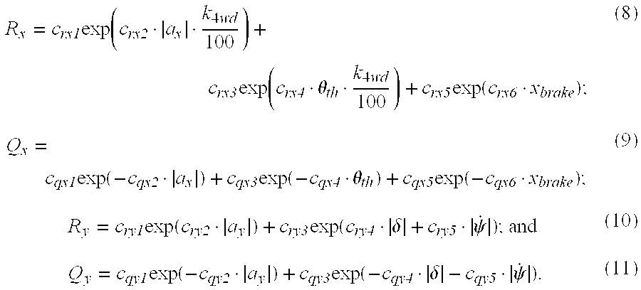
- the noise covariance module 42 uses Equations (8)-(11) listed below to determine the noise covariance (R x , Q x , R y , Q y ), respectively.
- the longitudinal measurement noise covariance, (R x ) and the longitudinal system noise covariance, (Q x ) are each the mathematical sum of three values—each value being an exponential function of one of an acceleration, throttle position and brake position.
- the summed values each also include a constant (i.e., C rxj and C qxj ).
- the constants are selected such that the magnitude of the covariance is “low” (“high reliability”) if the acceleration measurement from the accelerometer and at least on of the other measured values are indicative of the same vehicle operating state. For example, if the accelerometer indicates that the vehicle is accelerating and at least one of the throttle sensor or brake sensor provides a confirming indication of acceleration, Equations (8)-(9) provide a “low” noise covariance and therefore a “high reliability”. Conversely, if both the throttle and brake sensor readings are inconsistent with the acceleration reading, the exponential equations generate a “high” noise covariance indicating “low reliability”.
- R x c rx1 ⁇ exp ⁇ ( c rx2 ⁇ ⁇ a x ⁇ ⁇ k 4 ⁇ wd 100 ) + c rx3 ⁇ exp ⁇ ( c rx4 ⁇ ⁇ th ⁇ k 4 ⁇ wd 100 ) + c rx5 ⁇ exp ⁇ ( c rx6 ⁇ x brake ) ;
- Q x c qx1 ⁇ exp ⁇ ( - c qx2 ⁇ ⁇ a x ) + c qx3 ⁇ exp ⁇ ( - c qx4 ⁇ ⁇ th ) + c qx5 ⁇ exp ⁇ ( - c qx6 ⁇ x brake ) ;
- R y c ry1 ⁇ exp ⁇ ( c ry2 ⁇ ⁇ a y
- ⁇ th is the throttle angle
- x brake is the brake pedal travel
- k 4wd is the 4WD control parameter related with torque distribution ratio
- C qxi , C rxi , c gyi , and c ryi are positive real parameters determined through laboratory computer modeling or real world vehicle tests.
- the functional relationship of the noise covariance is generally exponential but other functional relationships may be used.
- the processor 12 determines the noise covariances, the processor communicates these values to a Kalman filter framework which calculates an estimated longitudinal velocity and an estimated lateral velocity (step 112 ).
- a Kalman filter module 44 which may be located within the processor 12 receives the longitudinal and lateral accelerations (a x , a y ), the yaw rate ( ⁇ dot over ( ⁇ ) ⁇ ), and the longitudinal and lateral approximated velocities ( ⁇ ax , ⁇ ay ) plus any other signals helpful in calculating the estimated velocities. Kalman filters are well known in the art for providing reliable state estimates in noisy environments.
- the Kalman filter is an unbiased estimator equation which minimizes the one-step predictor error covariance and includes the noise in the estimator gain.
- the Kalman filter framework used by the Kalman filter module 44 replaces the typical noise input with the noise covariance calculated in Equations (8)-(11).
- the estimated longitudinal and lateral absolute velocities of a vehicle can be decided by the following Kalman filter equations.
- R k [ R xk 0 0 R yk ]
- x ⁇ k ⁇ ⁇ k - 1 ⁇ v ⁇ rx k ⁇ ⁇ k - 1 v ⁇ ry k ⁇ ⁇ k - 1 ⁇
- k ⁇ 1 is the estimated longitudinal velocity
- k ⁇ 1 is the estimated lateral velocity
- the signals may be validated at step 104 to detect a sensor failure or eliminate any sensor signals outside of a normal range.
- the term normal range generally refers to the range of the signal that each sensor will produce during normal operating maneuvers. These ranges may be determined through real world testing or vehicle modeling. The normal range for sensor signals on a particular vehicle may be determined in laboratory bench tests, real world tests, vehicle modeling, or by any other means. If the signals lie within the range, those signals are considered valid while those outside are discarded.
- the signals may be conditioned or filtered at step 108 to reduce or alleviate variations or bad signals.
- the signal conditioning may be done through a variety of means that are well known in data processing.
- a simple low pass filter can be used for this purpose.
- a fx , and a fy which represent the filtered acceleration measurements, may be used in place of a x , and a y with the subscript “f” representing the filtered signal.
Abstract
Description


Claims (20)


Priority Applications (1)
| Application Number | Priority Date | Filing Date | Title |
|---|---|---|---|
| US10/454,658 US6816804B1 (en) | 2003-06-04 | 2003-06-04 | System and method for estimating velocity using reliability indexed sensor fusion |
Applications Claiming Priority (1)
| Application Number | Priority Date | Filing Date | Title |
|---|---|---|---|
| US10/454,658 US6816804B1 (en) | 2003-06-04 | 2003-06-04 | System and method for estimating velocity using reliability indexed sensor fusion |
Publications (1)
| Publication Number | Publication Date |
|---|---|
| US6816804B1 true US6816804B1 (en) | 2004-11-09 |
Family
ID=33310650
Family Applications (1)
| Application Number | Title | Priority Date | Filing Date |
|---|---|---|---|
| US10/454,658 Expired - Fee Related US6816804B1 (en) | 2003-06-04 | 2003-06-04 | System and method for estimating velocity using reliability indexed sensor fusion |
Country Status (1)
| Country | Link |
|---|---|
| US (1) | US6816804B1 (en) |
Cited By (45)
| Publication number | Priority date | Publication date | Assignee | Title |
|---|---|---|---|---|
| US20070005212A1 (en) * | 2005-06-10 | 2007-01-04 | Ford Global Technologies, Llc | Lateral and longitudinal velocity determination for an automotive vehicle |
| WO2007048973A1 (en) * | 2005-10-28 | 2007-05-03 | Peugeot Citroen Automobiles Sa | Method for determining a longitudinal velocity derivative of a motor vehicle |
| DE102005053666A1 (en) * | 2005-11-10 | 2007-05-16 | Hella Kgaa Hueck & Co | Method and device for correcting a vehicle speed |
| US20070174001A1 (en) * | 2004-03-23 | 2007-07-26 | Anders Kjell | Gear shifting system |
| WO2007083047A1 (en) * | 2006-01-20 | 2007-07-26 | Renault S.A.S. | Method for estimating the longitudinal speed of a motor vehicle |
| US20070295924A1 (en) * | 2006-06-22 | 2007-12-27 | Sauer-Danfoss Aps | Fluid controller and a method of detecting an error in a fluid controller |
| WO2008034672A1 (en) * | 2006-09-21 | 2008-03-27 | Robert Bosch Gmbh | Driver assistance system with data preparation according to function |
| EP1916166A1 (en) * | 2006-10-27 | 2008-04-30 | Ford Global Technologies, LLC | Method and apparatus for estimating longitudinal vehicle speed of an automotive vehicle |
| US20080172156A1 (en) * | 2007-01-16 | 2008-07-17 | Ford Global Technologies, Inc. | Method and system for impact time and velocity prediction |
| WO2008086850A1 (en) * | 2007-01-18 | 2008-07-24 | Wabco Gmbh | Method and device for determining the speed of a vehicle |
| US20090056686A1 (en) * | 2005-12-08 | 2009-03-05 | Toyota Jidosha Kabushiki Kaisha | Air-fuel ratio control apparatus and method for an internal combustion engine |
| EP1764526A3 (en) * | 2005-09-16 | 2009-07-29 | Zf Friedrichshafen Ag | Device for controlling a starting process of a vehicle |
| FR2932892A1 (en) * | 2008-06-23 | 2009-12-25 | Peugeot Citroen Automobiles Sa | Speed i.e. displacement speed, estimation device for four motorized wheeled motor vehicle, has logic controller providing speed of vehicle from acceleration signals provided by accelerometers |
| US20100131229A1 (en) * | 2008-11-24 | 2010-05-27 | Gm Global Technology Operations, Inc. | Dynamic observer for the estimation of vehicle lateral velocity |
| US20100131144A1 (en) * | 2008-11-24 | 2010-05-27 | Gm Global Technology Operations, Inc. | Kinematic estimator for vehicle lateral velocity using force tables |
| US20100241328A1 (en) * | 2007-09-25 | 2010-09-23 | Renault S.A.S. | Method for hill start assistance for motor vehicle |
| CN102582626A (en) * | 2012-02-16 | 2012-07-18 | 吉林大学 | Method for estimating heavy semitrailer status |
| CN103029709A (en) * | 2011-09-28 | 2013-04-10 | 通用汽车环球科技运作有限责任公司 | Method for determining the speed of a vehicle and vehicle |
| WO2013087169A1 (en) * | 2011-12-16 | 2013-06-20 | Audi Ag | Control device for a motor vehicle, motor vehicle, and method for configuring the control device |
| US20130325334A1 (en) * | 2012-05-31 | 2013-12-05 | International Electronic Machines Corporation | Pose Estimation |
| DE102013205245A1 (en) * | 2013-03-25 | 2014-09-25 | Continental Teves Ag & Co. Ohg | Vehicle reference speed determination method and vehicle control unit with such a method |
| US20150112569A1 (en) * | 2013-10-21 | 2015-04-23 | Yamaha Hatsudoki Kabushiki Kaisha | Longitudinal force control apparatus and saddled vehicle having the same |
| US9045142B2 (en) | 2013-08-26 | 2015-06-02 | Ford Global Technologies, Llc | Sensor fusion vehicle velocity estimation system and method |
| WO2015121110A1 (en) * | 2014-02-12 | 2015-08-20 | Jaguar Land Rover Limited | Apparatus and method for use in a vehicle |
| US20150291178A1 (en) * | 2014-04-10 | 2015-10-15 | Hyundai Motor Company | Apparatus and method for estimating vehicle velocity |
| WO2016139067A3 (en) * | 2015-03-03 | 2016-10-27 | Jaguar Land Rover Limited | Vehicle reference velocity estimation apparatus and method |
| WO2017025109A1 (en) * | 2015-08-10 | 2017-02-16 | Nira Dynamics Ab | Velocity estimation |
| EP2981832B1 (en) | 2013-06-04 | 2017-06-28 | Siemens Aktiengesellschaft | Method for determining at least one speed in a rail vehicle |
| DE102016215241A1 (en) * | 2016-08-16 | 2018-02-22 | Continental Automotive Gmbh | Method for determining a vehicle speed, control module and storage medium |
| CN108981733A (en) * | 2018-04-26 | 2018-12-11 | 杭州中恒云能源互联网技术有限公司 | A kind of speed predicting method of electric car charging navigation system |
| US10202125B2 (en) | 2017-04-12 | 2019-02-12 | GM Global Technology Operations LLC | Systems and methods for fault detection in lateral velocity estimation |
| CN109341711A (en) * | 2018-09-25 | 2019-02-15 | 杭州中恒云能源互联网技术有限公司 | A kind of prediction of speed algorithm for auto navigation |
| US10266202B2 (en) | 2017-04-12 | 2019-04-23 | GM Global Technology Operations LLC | Methods and systems for vehicle lateral force control |
| DE102008021715B4 (en) | 2007-05-07 | 2019-04-25 | GM Global Technology Operations LLC (n. d. Ges. d. Staates Delaware) | System for estimating vehicle conditions for rollover avoidance |
| CN110308300A (en) * | 2019-06-27 | 2019-10-08 | 厦门盈趣科技股份有限公司 | A kind of rotating speed measurement method and device merging multifrequency nature data |
| GB2574257A (en) * | 2018-06-01 | 2019-12-04 | Jaguar Land Rover Ltd | Vehicle dynamics estimation method and apparatus |
| CN111645699A (en) * | 2020-06-10 | 2020-09-11 | 北京理工大学 | Model self-adaptive lateral speed estimation method based on multi-sensor information fusion |
| DE102009029151B4 (en) * | 2009-09-03 | 2021-01-21 | Robert Bosch Gmbh | Method for determining a driving state variable in a vehicle |
| DE102019211944A1 (en) * | 2019-08-08 | 2021-02-11 | Knorr-Bremse Systeme für Schienenfahrzeuge GmbH | Method for determining a local carriage speed of a carriage |
| CN113771857A (en) * | 2021-09-24 | 2021-12-10 | 北京易航远智科技有限公司 | Longitudinal speed estimation method and system for vehicle control |
| US20220024400A1 (en) * | 2020-07-27 | 2022-01-27 | Robert Bosch Gmbh | Off-zone crash detection using lateral accelerations at different positions in a vehicle |
| US20220043403A1 (en) * | 2020-08-10 | 2022-02-10 | Robert Bosch Gmbh | Method for determining at least one system state by means of a kalman filter |
| CN114987611A (en) * | 2021-03-01 | 2022-09-02 | 沃尔沃卡车集团 | Low speed maneuver assist for a vehicle |
| US20230219561A1 (en) * | 2022-01-05 | 2023-07-13 | Motional Ad Llc | Vehicle state estimation augmenting sensor data for vehicle control and autonomous driving |
| US11787419B1 (en) * | 2021-10-22 | 2023-10-17 | Zoox, Inc. | Robust numerically stable Kalman filter for autonomous vehicles |
Citations (17)
| Publication number | Priority date | Publication date | Assignee | Title |
|---|---|---|---|---|
| US5371677A (en) * | 1990-09-28 | 1994-12-06 | Robert Bosch Gmbh | Method for determining the slip angles and/or the cornering forces of a braked vehicle |
| US5408411A (en) * | 1991-01-18 | 1995-04-18 | Hitachi, Ltd. | System for predicting behavior of automotive vehicle and for controlling vehicular behavior based thereon |
| US5416712A (en) | 1993-05-28 | 1995-05-16 | Trimble Navigation Limited | Position and velocity estimation system for adaptive weighting of GPS and dead-reckoning information |
| US5626140A (en) | 1995-11-01 | 1997-05-06 | Spacelabs Medical, Inc. | System and method of multi-sensor fusion of physiological measurements |
| US5676433A (en) | 1995-10-25 | 1997-10-14 | Toyota Jidosha Kabushiki Kaisha | Device for estimating side slide velocity of vehicle compatible with rolling and cant |
| US5711024A (en) | 1994-11-25 | 1998-01-20 | Itt Automotive Europe Gmbh | System for controlling yaw moment based on an estimated coefficient of friction |
| US5878357A (en) * | 1996-09-03 | 1999-03-02 | Ford Global Technologies, Inc. | Method and apparatus for vehicle yaw rate estimation |
| US5883595A (en) | 1997-09-15 | 1999-03-16 | Rockwell International Corporation | Method and apparatus for mitigating multipath effects and smoothing groundtracks in a GPS receiver |
| US5999890A (en) | 1996-10-25 | 1999-12-07 | Murata Manufacturing Co., Ltd. | Velocity calculating apparatus |
| US6081230A (en) | 1994-11-29 | 2000-06-27 | Xanavi Informatics Corporation | Navigation system furnished with means for estimating error of mounted sensor |
| US6092033A (en) | 1997-04-16 | 2000-07-18 | Uhlmann; Jeffrey K. | Method and apparatus for fusing mean and covariance estimates |
| US6161905A (en) | 1998-11-19 | 2000-12-19 | General Motors Corporation | Active brake control including estimation of yaw rate and slip angle |
| US6240367B1 (en) | 1998-11-27 | 2001-05-29 | Ching-Fang Lin | Full fusion positioning method for vehicle |
| US6269306B1 (en) | 2000-06-13 | 2001-07-31 | Ford Global Tech. | System and method for estimating sensor errors |
| US6311123B1 (en) | 1999-06-28 | 2001-10-30 | Hitachi, Ltd. | Vehicle control method and vehicle warning method |
| US6418369B2 (en) | 1999-12-16 | 2002-07-09 | Nissan Motor Co., Ltd. | Road surface friction coefficient estimating apparatus |
| US6609080B1 (en) * | 1999-11-22 | 2003-08-19 | Nokia Mobile Phones Ltd | Multiple-model navigation filter with hybrid positioning |
-
2003
- 2003-06-04 US US10/454,658 patent/US6816804B1/en not_active Expired - Fee Related
Patent Citations (17)
| Publication number | Priority date | Publication date | Assignee | Title |
|---|---|---|---|---|
| US5371677A (en) * | 1990-09-28 | 1994-12-06 | Robert Bosch Gmbh | Method for determining the slip angles and/or the cornering forces of a braked vehicle |
| US5408411A (en) * | 1991-01-18 | 1995-04-18 | Hitachi, Ltd. | System for predicting behavior of automotive vehicle and for controlling vehicular behavior based thereon |
| US5416712A (en) | 1993-05-28 | 1995-05-16 | Trimble Navigation Limited | Position and velocity estimation system for adaptive weighting of GPS and dead-reckoning information |
| US5711024A (en) | 1994-11-25 | 1998-01-20 | Itt Automotive Europe Gmbh | System for controlling yaw moment based on an estimated coefficient of friction |
| US6081230A (en) | 1994-11-29 | 2000-06-27 | Xanavi Informatics Corporation | Navigation system furnished with means for estimating error of mounted sensor |
| US5676433A (en) | 1995-10-25 | 1997-10-14 | Toyota Jidosha Kabushiki Kaisha | Device for estimating side slide velocity of vehicle compatible with rolling and cant |
| US5626140A (en) | 1995-11-01 | 1997-05-06 | Spacelabs Medical, Inc. | System and method of multi-sensor fusion of physiological measurements |
| US5878357A (en) * | 1996-09-03 | 1999-03-02 | Ford Global Technologies, Inc. | Method and apparatus for vehicle yaw rate estimation |
| US5999890A (en) | 1996-10-25 | 1999-12-07 | Murata Manufacturing Co., Ltd. | Velocity calculating apparatus |
| US6092033A (en) | 1997-04-16 | 2000-07-18 | Uhlmann; Jeffrey K. | Method and apparatus for fusing mean and covariance estimates |
| US5883595A (en) | 1997-09-15 | 1999-03-16 | Rockwell International Corporation | Method and apparatus for mitigating multipath effects and smoothing groundtracks in a GPS receiver |
| US6161905A (en) | 1998-11-19 | 2000-12-19 | General Motors Corporation | Active brake control including estimation of yaw rate and slip angle |
| US6240367B1 (en) | 1998-11-27 | 2001-05-29 | Ching-Fang Lin | Full fusion positioning method for vehicle |
| US6311123B1 (en) | 1999-06-28 | 2001-10-30 | Hitachi, Ltd. | Vehicle control method and vehicle warning method |
| US6609080B1 (en) * | 1999-11-22 | 2003-08-19 | Nokia Mobile Phones Ltd | Multiple-model navigation filter with hybrid positioning |
| US6418369B2 (en) | 1999-12-16 | 2002-07-09 | Nissan Motor Co., Ltd. | Road surface friction coefficient estimating apparatus |
| US6269306B1 (en) | 2000-06-13 | 2001-07-31 | Ford Global Tech. | System and method for estimating sensor errors |
Non-Patent Citations (10)
| Title |
|---|
| Bar-Shalom, Y. et al., "Chapter 2-State Estimation For Linear Systems," Tracking And Data Association, Academic Press, Inc., Mathematics in Science and Engineering, 1988 (pp. 9-79). |
| Farrelly, J. et al., "Estimation Of Vehicle Lateral Velocity Using State Observers," Proceedings Of The 1996 IEEE International Conference On Control Applications, Dearborn, MI, pp. 1-10, Jan. 1996. |
| Gustafsson, F. et al., "Sensor Fusion For Accurate Computation Of Yaw Rate And Absolute Velocity," Society of Automotive Engineers, Inc., 2001-01-1064, pp. 1-8 (2001). |
| Hac, A. et al., "Estimation Of Vehicle Side Slip Angle And Yaw Rate," Society Of Automotive Engineers, Inc. 2000-01-0606, pp. 1-7 (2000). |
| Hall, D.L., "Chapter 1-Introduction To Multisensor Data Fusion," Mathematical Techniques In Multisensor Data Fusion, Artech House, Inc., Norwood, MA, 1992 (pp. 1-34). |
| Jazwinski, Andrew H., "Stochastic Processes And Filtering Theory," Academic Press, New York, 1970 (pp. 234-243). |
| Lee, H., "Chapter 4-Reliability Indexed Sensor Fusion In An Adaptive Kalman Filter Framework," Robust Adaptive Control Using A Universal Approximator With Application To Vehicle Motion Control For IVHS, Ph.D. Dissertation, UC Berkley, 1997 (pp. 87-108). |
| Senger, K.H., et al., "Investigations On State Observers For The Lateral Dynamics Of Four-Wheel Steered Vehicles," Proceedings of the 11th International Association For Vehicle Systems Dynamics (IAVSD) Symposium, Kingston, Canada, 1989 (pp. 515-527). |
| Tseng, H.E., "Dynamic Estimation Of Road Bank Angle," Proceedings of AVEC 2000, 5th Int'l Symposium on Advanced Vehicle Control, Ann Arbor, MI, 8 pages, Aug. 22-24, 2000. |
| Wong, J.Y., Theory Of Ground Vehicles, 2nd Edition, John Wiley & Sons, Inc., New York, 2001 (pp. 303-309). |
Cited By (73)
| Publication number | Priority date | Publication date | Assignee | Title |
|---|---|---|---|---|
| US20070174001A1 (en) * | 2004-03-23 | 2007-07-26 | Anders Kjell | Gear shifting system |
| US7451033B2 (en) | 2005-06-10 | 2008-11-11 | Ford Global Technologies, Llc | Lateral and longitudinal velocity determination for an automotive vehicle |
| US20070005212A1 (en) * | 2005-06-10 | 2007-01-04 | Ford Global Technologies, Llc | Lateral and longitudinal velocity determination for an automotive vehicle |
| EP1764526A3 (en) * | 2005-09-16 | 2009-07-29 | Zf Friedrichshafen Ag | Device for controlling a starting process of a vehicle |
| WO2007048973A1 (en) * | 2005-10-28 | 2007-05-03 | Peugeot Citroen Automobiles Sa | Method for determining a longitudinal velocity derivative of a motor vehicle |
| FR2892823A1 (en) * | 2005-10-28 | 2007-05-04 | Peugeot Citroen Automobiles Sa | METHOD FOR DETERMINING A LONGITUDINAL SPEED DRIFT OF A MOTOR VEHICLE |
| DE102005053666A1 (en) * | 2005-11-10 | 2007-05-16 | Hella Kgaa Hueck & Co | Method and device for correcting a vehicle speed |
| US20090056686A1 (en) * | 2005-12-08 | 2009-03-05 | Toyota Jidosha Kabushiki Kaisha | Air-fuel ratio control apparatus and method for an internal combustion engine |
| FR2896467A1 (en) * | 2006-01-20 | 2007-07-27 | Renault Sas | METHOD FOR ESTIMATING THE LONGITUDINAL SPEED OF A MOTOR VEHICLE |
| WO2007083047A1 (en) * | 2006-01-20 | 2007-07-26 | Renault S.A.S. | Method for estimating the longitudinal speed of a motor vehicle |
| US7962310B2 (en) | 2006-01-20 | 2011-06-14 | Renault S.A.S. | Method for estimating the longitudinal speed of a motor vehicle |
| US20070295924A1 (en) * | 2006-06-22 | 2007-12-27 | Sauer-Danfoss Aps | Fluid controller and a method of detecting an error in a fluid controller |
| US8042568B2 (en) * | 2006-06-22 | 2011-10-25 | Sauer-Danfoss Aps | Fluid controller and a method of detecting an error in a fluid controller |
| WO2008034672A1 (en) * | 2006-09-21 | 2008-03-27 | Robert Bosch Gmbh | Driver assistance system with data preparation according to function |
| EP1916166A1 (en) * | 2006-10-27 | 2008-04-30 | Ford Global Technologies, LLC | Method and apparatus for estimating longitudinal vehicle speed of an automotive vehicle |
| US20080172156A1 (en) * | 2007-01-16 | 2008-07-17 | Ford Global Technologies, Inc. | Method and system for impact time and velocity prediction |
| EP1947474A1 (en) * | 2007-01-16 | 2008-07-23 | Ford Global Technologies, LLC | Method and system for impact time and velocity prediction |
| US8447472B2 (en) * | 2007-01-16 | 2013-05-21 | Ford Global Technologies, Llc | Method and system for impact time and velocity prediction |
| WO2008086850A1 (en) * | 2007-01-18 | 2008-07-24 | Wabco Gmbh | Method and device for determining the speed of a vehicle |
| CN101542297B (en) * | 2007-01-18 | 2013-05-08 | 威伯科有限公司 | Method and device for determining the speed of a vehicle |
| DE102008021715B4 (en) | 2007-05-07 | 2019-04-25 | GM Global Technology Operations LLC (n. d. Ges. d. Staates Delaware) | System for estimating vehicle conditions for rollover avoidance |
| US20100241328A1 (en) * | 2007-09-25 | 2010-09-23 | Renault S.A.S. | Method for hill start assistance for motor vehicle |
| US8463517B2 (en) | 2007-09-25 | 2013-06-11 | Renault S.A.S. | Method for hill start assistance for motor vehicle |
| FR2932892A1 (en) * | 2008-06-23 | 2009-12-25 | Peugeot Citroen Automobiles Sa | Speed i.e. displacement speed, estimation device for four motorized wheeled motor vehicle, has logic controller providing speed of vehicle from acceleration signals provided by accelerometers |
| US7908112B2 (en) * | 2008-11-24 | 2011-03-15 | GM Global Technology Operations LLC | Dynamic observer for the estimation of vehicle lateral velocity |
| US20100131144A1 (en) * | 2008-11-24 | 2010-05-27 | Gm Global Technology Operations, Inc. | Kinematic estimator for vehicle lateral velocity using force tables |
| US20100131229A1 (en) * | 2008-11-24 | 2010-05-27 | Gm Global Technology Operations, Inc. | Dynamic observer for the estimation of vehicle lateral velocity |
| US8050838B2 (en) * | 2008-11-24 | 2011-11-01 | GM Global Technology Operations LLC | Kinematic estimator for vehicle lateral velocity using force tables |
| DE102009029151B4 (en) * | 2009-09-03 | 2021-01-21 | Robert Bosch Gmbh | Method for determining a driving state variable in a vehicle |
| CN103029709A (en) * | 2011-09-28 | 2013-04-10 | 通用汽车环球科技运作有限责任公司 | Method for determining the speed of a vehicle and vehicle |
| WO2013087169A1 (en) * | 2011-12-16 | 2013-06-20 | Audi Ag | Control device for a motor vehicle, motor vehicle, and method for configuring the control device |
| CN102582626B (en) * | 2012-02-16 | 2015-06-10 | 吉林大学 | Method for estimating heavy semitrailer status |
| CN102582626A (en) * | 2012-02-16 | 2012-07-18 | 吉林大学 | Method for estimating heavy semitrailer status |
| US20130325334A1 (en) * | 2012-05-31 | 2013-12-05 | International Electronic Machines Corporation | Pose Estimation |
| US9482536B2 (en) * | 2012-05-31 | 2016-11-01 | International Electronic Machines Corp. | Pose estimation |
| DE102013205245A1 (en) * | 2013-03-25 | 2014-09-25 | Continental Teves Ag & Co. Ohg | Vehicle reference speed determination method and vehicle control unit with such a method |
| US9701289B2 (en) | 2013-03-25 | 2017-07-11 | Continental Teves Ag & Co. Ohg | Method for determining a vehicle reference speed and vehicle controller having such a method |
| US10459001B2 (en) | 2013-06-04 | 2019-10-29 | Siemens Mobility GmbH | Method for determining at least one speed in a rail vehicle |
| EP2981832B1 (en) | 2013-06-04 | 2017-06-28 | Siemens Aktiengesellschaft | Method for determining at least one speed in a rail vehicle |
| US9045142B2 (en) | 2013-08-26 | 2015-06-02 | Ford Global Technologies, Llc | Sensor fusion vehicle velocity estimation system and method |
| US20150112569A1 (en) * | 2013-10-21 | 2015-04-23 | Yamaha Hatsudoki Kabushiki Kaisha | Longitudinal force control apparatus and saddled vehicle having the same |
| US9079584B2 (en) * | 2013-10-21 | 2015-07-14 | Yamaha Hatsudoki Kabushiki Kaisha | Longitudinal force control apparatus and saddled vehicle having the same |
| WO2015121110A1 (en) * | 2014-02-12 | 2015-08-20 | Jaguar Land Rover Limited | Apparatus and method for use in a vehicle |
| US10059343B2 (en) | 2014-02-12 | 2018-08-28 | Jaguar Land Rover Limited | Apparatus and method for use in a vehicle |
| US20150291178A1 (en) * | 2014-04-10 | 2015-10-15 | Hyundai Motor Company | Apparatus and method for estimating vehicle velocity |
| WO2016139067A3 (en) * | 2015-03-03 | 2016-10-27 | Jaguar Land Rover Limited | Vehicle reference velocity estimation apparatus and method |
| US10363939B2 (en) | 2015-03-03 | 2019-07-30 | Jaguar Land Rover Limited | Vehicle reference velocity estimation apparatus and method |
| CN107406080A (en) * | 2015-03-03 | 2017-11-28 | 捷豹路虎有限公司 | Vehicle reference velocity estimation apparatus and method |
| CN108139422A (en) * | 2015-08-10 | 2018-06-08 | 尼拉动力公司 | Velocity estimation |
| US10969401B2 (en) | 2015-08-10 | 2021-04-06 | Nira Dynamics Ab | Velocity estimation |
| WO2017025109A1 (en) * | 2015-08-10 | 2017-02-16 | Nira Dynamics Ab | Velocity estimation |
| DE102016215241A1 (en) * | 2016-08-16 | 2018-02-22 | Continental Automotive Gmbh | Method for determining a vehicle speed, control module and storage medium |
| US10202125B2 (en) | 2017-04-12 | 2019-02-12 | GM Global Technology Operations LLC | Systems and methods for fault detection in lateral velocity estimation |
| US10266202B2 (en) | 2017-04-12 | 2019-04-23 | GM Global Technology Operations LLC | Methods and systems for vehicle lateral force control |
| CN108981733B (en) * | 2018-04-26 | 2020-11-24 | 杭州中恒云能源互联网技术有限公司 | Speed prediction method of electric vehicle charging navigation system |
| CN108981733A (en) * | 2018-04-26 | 2018-12-11 | 杭州中恒云能源互联网技术有限公司 | A kind of speed predicting method of electric car charging navigation system |
| GB2574257A (en) * | 2018-06-01 | 2019-12-04 | Jaguar Land Rover Ltd | Vehicle dynamics estimation method and apparatus |
| GB2574257B (en) * | 2018-06-01 | 2021-06-30 | Jaguar Land Rover Ltd | Vehicle dynamics estimation method and apparatus |
| CN109341711B (en) * | 2018-09-25 | 2021-01-05 | 杭州中恒云能源互联网技术有限公司 | Speed prediction algorithm for automobile navigation |
| CN109341711A (en) * | 2018-09-25 | 2019-02-15 | 杭州中恒云能源互联网技术有限公司 | A kind of prediction of speed algorithm for auto navigation |
| CN110308300B (en) * | 2019-06-27 | 2021-09-21 | 厦门盈趣科技股份有限公司 | Rotating speed measuring method and device fusing multiple characteristic data |
| CN110308300A (en) * | 2019-06-27 | 2019-10-08 | 厦门盈趣科技股份有限公司 | A kind of rotating speed measurement method and device merging multifrequency nature data |
| DE102019211944A1 (en) * | 2019-08-08 | 2021-02-11 | Knorr-Bremse Systeme für Schienenfahrzeuge GmbH | Method for determining a local carriage speed of a carriage |
| CN111645699A (en) * | 2020-06-10 | 2020-09-11 | 北京理工大学 | Model self-adaptive lateral speed estimation method based on multi-sensor information fusion |
| JP2022541082A (en) * | 2020-06-10 | 2022-09-22 | 北京理工大学 | Model-adaptive lateral velocity estimation method based on multi-sensor information fusion |
| JP7361242B2 (en) | 2020-06-10 | 2023-10-16 | 北京理工大学 | Model adaptive lateral velocity estimation method based on multi-sensor information fusion |
| US20220024400A1 (en) * | 2020-07-27 | 2022-01-27 | Robert Bosch Gmbh | Off-zone crash detection using lateral accelerations at different positions in a vehicle |
| US11648900B2 (en) * | 2020-07-27 | 2023-05-16 | Robert Bosch Gmbh | Off-zone crash detection using lateral accelerations at different positions in a vehicle |
| US20220043403A1 (en) * | 2020-08-10 | 2022-02-10 | Robert Bosch Gmbh | Method for determining at least one system state by means of a kalman filter |
| CN114987611A (en) * | 2021-03-01 | 2022-09-02 | 沃尔沃卡车集团 | Low speed maneuver assist for a vehicle |
| CN113771857A (en) * | 2021-09-24 | 2021-12-10 | 北京易航远智科技有限公司 | Longitudinal speed estimation method and system for vehicle control |
| US11787419B1 (en) * | 2021-10-22 | 2023-10-17 | Zoox, Inc. | Robust numerically stable Kalman filter for autonomous vehicles |
| US20230219561A1 (en) * | 2022-01-05 | 2023-07-13 | Motional Ad Llc | Vehicle state estimation augmenting sensor data for vehicle control and autonomous driving |
Similar Documents
| Publication | Publication Date | Title |
|---|---|---|
| US6816804B1 (en) | System and method for estimating velocity using reliability indexed sensor fusion | |
| US6351694B1 (en) | Method for robust estimation of road bank angle | |
| US7092808B2 (en) | Integrated sensing system for an automotive system | |
| US6829524B2 (en) | Method and apparatus for estimating yaw rate in a wheeled vehicle and stability system | |
| US7899594B2 (en) | System and method for qualitatively determining vehicle loading conditions | |
| US7599779B2 (en) | Acceleration estimation device and vehicle | |
| US6804584B2 (en) | Method for determining the roll angle of a vehicle using an estimation of road bank angle | |
| US7522985B2 (en) | Method and arrangement for monitoring a measuring device located in a wheeled vehicle | |
| US10040460B2 (en) | Corner-based longitudinal speed estimation | |
| US7536272B2 (en) | Method and device for estimating the total mass of a motor vehicle | |
| US7499826B2 (en) | Method of estimating mass for vehicle safety | |
| JP2001519285A (en) | How to determine the state variables of a car | |
| US20090177346A1 (en) | Dynamic estimation of vehicle inertial parameters and tire forces from tire sensors | |
| US7317982B2 (en) | Estimating device and vehicle motion control device using the same | |
| US7292925B1 (en) | Acceleration estimation device and vehicle | |
| US10435028B2 (en) | Vehicle state estimation apparatus and method | |
| US20060267750A1 (en) | Tire abnormal state monitoring system for an automotive vehicle | |
| US20100106360A1 (en) | System and method for dynamically determining vehicle loading and vertical loading distance for use in a vehicle dynamic control system | |
| US20030163237A1 (en) | Method of controlling traveling stability of vehicle | |
| CN106232446B (en) | Method for determining an error of an inertial sensor | |
| JPH1035443A (en) | Apparatus for presuming car body speed and coefficient of friction on road surface | |
| CN105073526A (en) | Method for determining a vehicle reference speed and vehicle controller having such a method | |
| CN107264535B (en) | A kind of complete vehicle quality estimation method based on Frequency Response | |
| US8340881B2 (en) | Method and system for assessing vehicle movement | |
| KR20200055155A (en) | Method to determine the roll angle of a motorcycle |
Legal Events
| Date | Code | Title | Description |
|---|---|---|---|
| AS | Assignment |
Owner name: VISTEON GLOBAL TECHNOLOGIES, INC., MICHIGAN Free format text: ASSIGNMENT OF ASSIGNORS INTEREST;ASSIGNOR:LEE, HYEONGCHEOL;REEL/FRAME:014144/0087 Effective date: 20030603 |
|
| FEPP | Fee payment procedure |
Free format text: PAYOR NUMBER ASSIGNED (ORIGINAL EVENT CODE: ASPN); ENTITY STATUS OF PATENT OWNER: LARGE ENTITY |
|
| CC | Certificate of correction | ||
| CC | Certificate of correction | ||
| AS | Assignment |
Owner name: JPMORGAN CHASE BANK, N.A., AS ADMINISTRATIVE AGENT Free format text: SECURITY AGREEMENT;ASSIGNOR:VISTEON GLOBAL TECHNOLOGIES, INC.;REEL/FRAME:020497/0733 Effective date: 20060613 |
|
| FPAY | Fee payment |
Year of fee payment: 4 |
|
| AS | Assignment |
Owner name: JPMORGAN CHASE BANK, TEXAS Free format text: SECURITY INTEREST;ASSIGNOR:VISTEON GLOBAL TECHNOLOGIES, INC.;REEL/FRAME:022368/0001 Effective date: 20060814 Owner name: JPMORGAN CHASE BANK,TEXAS Free format text: SECURITY INTEREST;ASSIGNOR:VISTEON GLOBAL TECHNOLOGIES, INC.;REEL/FRAME:022368/0001 Effective date: 20060814 |
|
| AS | Assignment |
Owner name: WILMINGTON TRUST FSB, AS ADMINISTRATIVE AGENT, MIN Free format text: ASSIGNMENT OF SECURITY INTEREST IN PATENTS;ASSIGNOR:JPMORGAN CHASE BANK, N.A., AS ADMINISTRATIVE AGENT;REEL/FRAME:022575/0186 Effective date: 20090415 Owner name: WILMINGTON TRUST FSB, AS ADMINISTRATIVE AGENT,MINN Free format text: ASSIGNMENT OF SECURITY INTEREST IN PATENTS;ASSIGNOR:JPMORGAN CHASE BANK, N.A., AS ADMINISTRATIVE AGENT;REEL/FRAME:022575/0186 Effective date: 20090415 |
|
| AS | Assignment |
Owner name: THE BANK OF NEW YORK MELLON, AS ADMINISTRATIVE AGE Free format text: ASSIGNMENT OF PATENT SECURITY INTEREST;ASSIGNOR:JPMORGAN CHASE BANK, N.A., A NATIONAL BANKING ASSOCIATION;REEL/FRAME:022974/0057 Effective date: 20090715 |
|
| AS | Assignment |
Owner name: VISTEON GLOBAL TECHNOLOGIES, INC., MICHIGAN Free format text: RELEASE BY SECURED PARTY AGAINST SECURITY INTEREST IN PATENTS RECORDED AT REEL 022974 FRAME 0057;ASSIGNOR:THE BANK OF NEW YORK MELLON;REEL/FRAME:025095/0711 Effective date: 20101001 |
|
| AS | Assignment |
Owner name: VISTEON GLOBAL TECHNOLOGIES, INC., MICHIGAN Free format text: RELEASE BY SECURED PARTY AGAINST SECURITY INTEREST IN PATENTS RECORDED AT REEL 022575 FRAME 0186;ASSIGNOR:WILMINGTON TRUST FSB, AS ADMINISTRATIVE AGENT;REEL/FRAME:025105/0201 Effective date: 20101001 |
|
| AS | Assignment |
Owner name: MORGAN STANLEY SENIOR FUNDING, INC., AS AGENT, NEW Free format text: SECURITY AGREEMENT;ASSIGNORS:VISTEON CORPORATION;VC AVIATION SERVICES, LLC;VISTEON ELECTRONICS CORPORATION;AND OTHERS;REEL/FRAME:025241/0317 Effective date: 20101007 Owner name: MORGAN STANLEY SENIOR FUNDING, INC., AS AGENT, NEW Free format text: SECURITY AGREEMENT (REVOLVER);ASSIGNORS:VISTEON CORPORATION;VC AVIATION SERVICES, LLC;VISTEON ELECTRONICS CORPORATION;AND OTHERS;REEL/FRAME:025238/0298 Effective date: 20101001 |
|
| AS | Assignment |
Owner name: VISTEON INTERNATIONAL BUSINESS DEVELOPMENT, INC., Free format text: RELEASE BY SECURED PARTY AGAINST SECURITY INTEREST IN PATENTS ON REEL 025241 FRAME 0317;ASSIGNOR:MORGAN STANLEY SENIOR FUNDING, INC.;REEL/FRAME:026178/0412 Effective date: 20110406 Owner name: VISTEON CORPORATION, MICHIGAN Free format text: RELEASE BY SECURED PARTY AGAINST SECURITY INTEREST IN PATENTS ON REEL 025241 FRAME 0317;ASSIGNOR:MORGAN STANLEY SENIOR FUNDING, INC.;REEL/FRAME:026178/0412 Effective date: 20110406 Owner name: VISTEON EUROPEAN HOLDING, INC., MICHIGAN Free format text: RELEASE BY SECURED PARTY AGAINST SECURITY INTEREST IN PATENTS ON REEL 025241 FRAME 0317;ASSIGNOR:MORGAN STANLEY SENIOR FUNDING, INC.;REEL/FRAME:026178/0412 Effective date: 20110406 Owner name: VISTEON GLOBAL TREASURY, INC., MICHIGAN Free format text: RELEASE BY SECURED PARTY AGAINST SECURITY INTEREST IN PATENTS ON REEL 025241 FRAME 0317;ASSIGNOR:MORGAN STANLEY SENIOR FUNDING, INC.;REEL/FRAME:026178/0412 Effective date: 20110406 Owner name: VISTEON GLOBAL TECHNOLOGIES, INC., MICHIGAN Free format text: RELEASE BY SECURED PARTY AGAINST SECURITY INTEREST IN PATENTS ON REEL 025241 FRAME 0317;ASSIGNOR:MORGAN STANLEY SENIOR FUNDING, INC.;REEL/FRAME:026178/0412 Effective date: 20110406 Owner name: VISTEON INTERNATIONAL HOLDINGS, INC., MICHIGAN Free format text: RELEASE BY SECURED PARTY AGAINST SECURITY INTEREST IN PATENTS ON REEL 025241 FRAME 0317;ASSIGNOR:MORGAN STANLEY SENIOR FUNDING, INC.;REEL/FRAME:026178/0412 Effective date: 20110406 Owner name: VC AVIATION SERVICES, LLC, MICHIGAN Free format text: RELEASE BY SECURED PARTY AGAINST SECURITY INTEREST IN PATENTS ON REEL 025241 FRAME 0317;ASSIGNOR:MORGAN STANLEY SENIOR FUNDING, INC.;REEL/FRAME:026178/0412 Effective date: 20110406 Owner name: VISTEON ELECTRONICS CORPORATION, MICHIGAN Free format text: RELEASE BY SECURED PARTY AGAINST SECURITY INTEREST IN PATENTS ON REEL 025241 FRAME 0317;ASSIGNOR:MORGAN STANLEY SENIOR FUNDING, INC.;REEL/FRAME:026178/0412 Effective date: 20110406 Owner name: VISTEON SYSTEMS, LLC, MICHIGAN Free format text: RELEASE BY SECURED PARTY AGAINST SECURITY INTEREST IN PATENTS ON REEL 025241 FRAME 0317;ASSIGNOR:MORGAN STANLEY SENIOR FUNDING, INC.;REEL/FRAME:026178/0412 Effective date: 20110406 |
|
| REMI | Maintenance fee reminder mailed | ||
| LAPS | Lapse for failure to pay maintenance fees | ||
| STCH | Information on status: patent discontinuation |
Free format text: PATENT EXPIRED DUE TO NONPAYMENT OF MAINTENANCE FEES UNDER 37 CFR 1.362 |
|
| FP | Lapsed due to failure to pay maintenance fee |
Effective date: 20121109 |
|
| AS | Assignment |
Owner name: VISTEON INTERNATIONAL BUSINESS DEVELOPMENT, INC., Free format text: RELEASE OF SECURITY INTEREST IN INTELLECTUAL PROPERTY;ASSIGNOR:MORGAN STANLEY SENIOR FUNDING, INC.;REEL/FRAME:033107/0717 Effective date: 20140409 Owner name: VISTEON GLOBAL TECHNOLOGIES, INC., MICHIGAN Free format text: RELEASE OF SECURITY INTEREST IN INTELLECTUAL PROPERTY;ASSIGNOR:MORGAN STANLEY SENIOR FUNDING, INC.;REEL/FRAME:033107/0717 Effective date: 20140409 Owner name: VC AVIATION SERVICES, LLC, MICHIGAN Free format text: RELEASE OF SECURITY INTEREST IN INTELLECTUAL PROPERTY;ASSIGNOR:MORGAN STANLEY SENIOR FUNDING, INC.;REEL/FRAME:033107/0717 Effective date: 20140409 Owner name: VISTEON GLOBAL TREASURY, INC., MICHIGAN Free format text: RELEASE OF SECURITY INTEREST IN INTELLECTUAL PROPERTY;ASSIGNOR:MORGAN STANLEY SENIOR FUNDING, INC.;REEL/FRAME:033107/0717 Effective date: 20140409 Owner name: VISTEON SYSTEMS, LLC, MICHIGAN Free format text: RELEASE OF SECURITY INTEREST IN INTELLECTUAL PROPERTY;ASSIGNOR:MORGAN STANLEY SENIOR FUNDING, INC.;REEL/FRAME:033107/0717 Effective date: 20140409 Owner name: VISTEON EUROPEAN HOLDINGS, INC., MICHIGAN Free format text: RELEASE OF SECURITY INTEREST IN INTELLECTUAL PROPERTY;ASSIGNOR:MORGAN STANLEY SENIOR FUNDING, INC.;REEL/FRAME:033107/0717 Effective date: 20140409 Owner name: VISTEON ELECTRONICS CORPORATION, MICHIGAN Free format text: RELEASE OF SECURITY INTEREST IN INTELLECTUAL PROPERTY;ASSIGNOR:MORGAN STANLEY SENIOR FUNDING, INC.;REEL/FRAME:033107/0717 Effective date: 20140409 Owner name: VISTEON CORPORATION, MICHIGAN Free format text: RELEASE OF SECURITY INTEREST IN INTELLECTUAL PROPERTY;ASSIGNOR:MORGAN STANLEY SENIOR FUNDING, INC.;REEL/FRAME:033107/0717 Effective date: 20140409 Owner name: VISTEON INTERNATIONAL HOLDINGS, INC., MICHIGAN Free format text: RELEASE OF SECURITY INTEREST IN INTELLECTUAL PROPERTY;ASSIGNOR:MORGAN STANLEY SENIOR FUNDING, INC.;REEL/FRAME:033107/0717 Effective date: 20140409 |