US6818830B2 - H-tap compression connector - Google Patents
H-tap compression connector Download PDFInfo
- Publication number
- US6818830B2 US6818830B2 US10/668,847 US66884703A US6818830B2 US 6818830 B2 US6818830 B2 US 6818830B2 US 66884703 A US66884703 A US 66884703A US 6818830 B2 US6818830 B2 US 6818830B2
- Authority
- US
- United States
- Prior art keywords
- pair
- compression connector
- body portion
- leg portions
- slots
- Prior art date
- Legal status (The legal status is an assumption and is not a legal conclusion. Google has not performed a legal analysis and makes no representation as to the accuracy of the status listed.)
- Expired - Lifetime
Links
Images


Classifications
-
- H—ELECTRICITY
- H01—ELECTRIC ELEMENTS
- H01R—ELECTRICALLY-CONDUCTIVE CONNECTIONS; STRUCTURAL ASSOCIATIONS OF A PLURALITY OF MUTUALLY-INSULATED ELECTRICAL CONNECTING ELEMENTS; COUPLING DEVICES; CURRENT COLLECTORS
- H01R4/00—Electrically-conductive connections between two or more conductive members in direct contact, i.e. touching one another; Means for effecting or maintaining such contact; Electrically-conductive connections having two or more spaced connecting locations for conductors and using contact members penetrating insulation
- H01R4/10—Electrically-conductive connections between two or more conductive members in direct contact, i.e. touching one another; Means for effecting or maintaining such contact; Electrically-conductive connections having two or more spaced connecting locations for conductors and using contact members penetrating insulation effected solely by twisting, wrapping, bending, crimping, or other permanent deformation
- H01R4/18—Electrically-conductive connections between two or more conductive members in direct contact, i.e. touching one another; Means for effecting or maintaining such contact; Electrically-conductive connections having two or more spaced connecting locations for conductors and using contact members penetrating insulation effected solely by twisting, wrapping, bending, crimping, or other permanent deformation by crimping
- H01R4/183—Electrically-conductive connections between two or more conductive members in direct contact, i.e. touching one another; Means for effecting or maintaining such contact; Electrically-conductive connections having two or more spaced connecting locations for conductors and using contact members penetrating insulation effected solely by twisting, wrapping, bending, crimping, or other permanent deformation by crimping for cylindrical elongated bodies, e.g. cables having circular cross-section
- H01R4/186—Electrically-conductive connections between two or more conductive members in direct contact, i.e. touching one another; Means for effecting or maintaining such contact; Electrically-conductive connections having two or more spaced connecting locations for conductors and using contact members penetrating insulation effected solely by twisting, wrapping, bending, crimping, or other permanent deformation by crimping for cylindrical elongated bodies, e.g. cables having circular cross-section using a body comprising a plurality of cable-accommodating recesses or bores
-
- F—MECHANICAL ENGINEERING; LIGHTING; HEATING; WEAPONS; BLASTING
- F16—ENGINEERING ELEMENTS AND UNITS; GENERAL MEASURES FOR PRODUCING AND MAINTAINING EFFECTIVE FUNCTIONING OF MACHINES OR INSTALLATIONS; THERMAL INSULATION IN GENERAL
- F16G—BELTS, CABLES, OR ROPES, PREDOMINANTLY USED FOR DRIVING PURPOSES; CHAINS; FITTINGS PREDOMINANTLY USED THEREFOR
- F16G11/00—Means for fastening cables or ropes to one another or to other objects; Caps or sleeves for fixing on cables or ropes
- F16G11/02—Means for fastening cables or ropes to one another or to other objects; Caps or sleeves for fixing on cables or ropes with parts deformable to grip the cable or cables; Fastening means which engage a sleeve or the like fixed on the cable
-
- H—ELECTRICITY
- H01—ELECTRIC ELEMENTS
- H01R—ELECTRICALLY-CONDUCTIVE CONNECTIONS; STRUCTURAL ASSOCIATIONS OF A PLURALITY OF MUTUALLY-INSULATED ELECTRICAL CONNECTING ELEMENTS; COUPLING DEVICES; CURRENT COLLECTORS
- H01R4/00—Electrically-conductive connections between two or more conductive members in direct contact, i.e. touching one another; Means for effecting or maintaining such contact; Electrically-conductive connections having two or more spaced connecting locations for conductors and using contact members penetrating insulation
- H01R4/10—Electrically-conductive connections between two or more conductive members in direct contact, i.e. touching one another; Means for effecting or maintaining such contact; Electrically-conductive connections having two or more spaced connecting locations for conductors and using contact members penetrating insulation effected solely by twisting, wrapping, bending, crimping, or other permanent deformation
- H01R4/18—Electrically-conductive connections between two or more conductive members in direct contact, i.e. touching one another; Means for effecting or maintaining such contact; Electrically-conductive connections having two or more spaced connecting locations for conductors and using contact members penetrating insulation effected solely by twisting, wrapping, bending, crimping, or other permanent deformation by crimping
- H01R4/20—Electrically-conductive connections between two or more conductive members in direct contact, i.e. touching one another; Means for effecting or maintaining such contact; Electrically-conductive connections having two or more spaced connecting locations for conductors and using contact members penetrating insulation effected solely by twisting, wrapping, bending, crimping, or other permanent deformation by crimping using a crimping sleeve
- H01R4/203—Electrically-conductive connections between two or more conductive members in direct contact, i.e. touching one another; Means for effecting or maintaining such contact; Electrically-conductive connections having two or more spaced connecting locations for conductors and using contact members penetrating insulation effected solely by twisting, wrapping, bending, crimping, or other permanent deformation by crimping using a crimping sleeve having an uneven wire-receiving surface to improve the contact
- H01R4/206—Electrically-conductive connections between two or more conductive members in direct contact, i.e. touching one another; Means for effecting or maintaining such contact; Electrically-conductive connections having two or more spaced connecting locations for conductors and using contact members penetrating insulation effected solely by twisting, wrapping, bending, crimping, or other permanent deformation by crimping using a crimping sleeve having an uneven wire-receiving surface to improve the contact with transversal grooves or threads
-
- Y—GENERAL TAGGING OF NEW TECHNOLOGICAL DEVELOPMENTS; GENERAL TAGGING OF CROSS-SECTIONAL TECHNOLOGIES SPANNING OVER SEVERAL SECTIONS OF THE IPC; TECHNICAL SUBJECTS COVERED BY FORMER USPC CROSS-REFERENCE ART COLLECTIONS [XRACs] AND DIGESTS
- Y10—TECHNICAL SUBJECTS COVERED BY FORMER USPC
- Y10T—TECHNICAL SUBJECTS COVERED BY FORMER US CLASSIFICATION
- Y10T29/00—Metal working
- Y10T29/49—Method of mechanical manufacture
- Y10T29/49002—Electrical device making
- Y10T29/49117—Conductor or circuit manufacturing
- Y10T29/49194—Assembling elongated conductors, e.g., splicing, etc.
- Y10T29/49195—Assembling elongated conductors, e.g., splicing, etc. with end-to-end orienting
- Y10T29/49199—Assembling elongated conductors, e.g., splicing, etc. with end-to-end orienting including deforming of joining bridge
-
- Y—GENERAL TAGGING OF NEW TECHNOLOGICAL DEVELOPMENTS; GENERAL TAGGING OF CROSS-SECTIONAL TECHNOLOGIES SPANNING OVER SEVERAL SECTIONS OF THE IPC; TECHNICAL SUBJECTS COVERED BY FORMER USPC CROSS-REFERENCE ART COLLECTIONS [XRACs] AND DIGESTS
- Y10—TECHNICAL SUBJECTS COVERED BY FORMER USPC
- Y10T—TECHNICAL SUBJECTS COVERED BY FORMER US CLASSIFICATION
- Y10T29/00—Metal working
- Y10T29/49—Method of mechanical manufacture
- Y10T29/49002—Electrical device making
- Y10T29/49117—Conductor or circuit manufacturing
- Y10T29/49194—Assembling elongated conductors, e.g., splicing, etc.
- Y10T29/49201—Assembling elongated conductors, e.g., splicing, etc. with overlapping orienting
Definitions
- the present invention is directed to an H-tap compression connector and, more particularly, to an H-tap compression connector with an easy installation feature and a longitudinally-oriented hole therethrough.
- H-tap compression connectors can be found in the following U.S. Pat. Nos. 2,307,216; 3,183,025; 3,235,654; 3,354,517; 5,162,615; 5,396,033; 5,552,564; 5,635,676; and 6,525,270.
- none of these prior art compression connectors have a transversely-oriented slot extending between a first pair of slots on one side of the compression connector and a second pair of slots on the other side of the compression connector.
- none of these prior art compression connectors have a longitudinally-oriented hole extending through the center of the compression connector.
- a compression connector for securing wires therein has a first body portion connected to a second body portion. Each of the first and second body portions has two pairs of leg portions extending therefrom to form two conductor receiving channels, respectively.
- the compression connector also has a first pair of slots and a second pair of slots for receiving a cable tie to secure wires therein before crimping.
- a transversely-oriented slot extends between the first pair of slots and the second pair of slots, and an aperture extends through the first body portion or the second body portion.
- the aperture extends either longitudinally or transversely through the compression connector, and a central body portion connects the first body portion and the second body portion.
- the aperture may extend through: 1) the first body portion and the central body portion; 2) the second body portion and the central body portion; or 3) the first body portion, the central body portion and the second body portion.
- the first and second pair of leg portions have diagonally opposed symmetry, and are substantially parallel or curved.
- the first and second pair of leg portions have same-side symmetry, and are substantially parallel or curved.
- the third and fourth pair of leg portions have diagonally opposed symmetry, and are substantially parallel or curved.
- the third and fourth pair of leg portions have same-side symmetry, and are substantially parallel or curved.
- FIG. 1 is a perspective view of a compression connector of the present invention shown secured around run and tap wires after crimping;
- FIG. 2 is a perspective view of the compression connector of FIG. 1;
- FIG. 3 is a front view of the compression connector of FIG. 1;
- FIG. 4 is a right side view of the compression connector of FIG. 1;
- FIG. 5 is a cross-sectional view of the compression connector taken along lines 5 — 5 of FIG. 4;
- FIG. 6 is a front view of the compression connector of FIG. 1 after the run and tap wires have been secured but before crimping;
- FIG. 7 is a front view of the compression connector of FIG. 1 after crimping
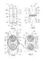
- FIG. 8 is a perspective view of a compression connector according to a second embodiment of the present invention.
- FIG. 9 is a front view of the compression connector of FIG. 8;
- FIG. 10 is a right side view of the compression connector of FIG. 8;
- FIG. 11 is a perspective view of a compression connector according to a third embodiment of the present invention.
- FIG. 12 is a front view of the compression connector of FIG. 11;
- FIG. 13 is a right side view of the compression connector of FIG. 11;
- FIG. 14 is a perspective view of a compression connector according to a fourth embodiment of the present invention shown secured around run and tap wires after crimping;
- FIG. 15 is a perspective view of the compression connector of FIG. 14;
- FIG. 16 is a left side view of the compression connector of FIG. 14;
- FIG. 17 is a cross-sectional view of the compression connector taken along lines 17 — 17 of FIG. 16;
- FIG. 18 is a front view of the compression connector of FIG. 14 after the run and tap wires have been secured but before crimping;
- FIG. 19 is a front view of the compression connector of FIG. 14 after crimping.
- FIG. 20 is a cross-sectional view of the compression connector taken along lines 20 — 20 of FIG. 19 .
- the illustrated embodiments of the invention are directed to an H-tap compression connector having a pair of slots cut through both sides to provide a space to loop a cable tie around wires in the compression connector to secure the wires before crimping, and a transversely-oriented slot extending between the compression connector sides.
- the compression connector has a longitudinally-oriented hole therethrough.
- FIG. 1 shows an H-tap compression connector 20 secured around wires, such as run wires 22 and tap wires 24 , after crimping.
- compression connector 20 is a one-piece member made of electrically conductive material, such as copper.
- compression connector 20 may be made of any suitable materials or elements.
- compression connector 20 has a first section 26 and a second section 28 .
- First section 26 includes a first body portion 30 having four leg portions 32 , 34 , 36 , 38 extending therefrom to form conductor receiving channels 40 , 42 in which run wires 22 and tap wires 24 can be placed.
- Second section 28 is identical to first section 26 .
- second section 28 includes a second body portion 44 having four leg portions 46 , 48 , 50 , 52 extending therefrom to form conductor receiving channels 54 , 56 in which run wires 22 and tap wires 24 can be placed.
- a central body portion 58 connects first body portion 30 and second body portion 44 .
- compression connector 20 includes four slots 60 , 61 , 62 , 63 cut through the sides of compression connector 20 .
- Slots 60 , 61 , 62 , 63 provide space to loop a cable tie 64 to secure run wires 22 and tap wires 24 to compression connector 20 before crimping, as shown in FIG. 6 .
- a transversely-oriented slot 66 extends between slots 60 , 62 , and as best seen in FIGS. 3 and 5, slot 66 is positioned below conductor receiving channels 40 , 54 .
- a transversely-oriented slot 67 extends between slots 61 , 63 , and as best seen in FIG.
- slot 67 is positioned above conductor receiving channels 42 , 56 .
- Slots 60 , 61 , 62 , 63 allow crimped wire material to flow between first section 26 and second section 28 .
- the wire material that flows between first section 26 and second section 28 fills slots 66 , 67 creating a mechanical lock.
- slots 66 , 67 increase wire pullout force and, in turn, increase the mechanical strength of compression connector 20 .
- run wires 22 and tap wires 24 are inserted into compression connector 20 and retained in position prior to crimping using cable tie 64 , as shown in FIG. 6 .
- a first cable tie may be utilized to secure tap wires 24 to compression connector 20
- a second cable tie may be utilized to secure run wires 22 and tap wires 24 to compression connector 20 .
- Compression connector 20 is crimped with cable tie 64 in place using a crimp tool, such as Panduit® CT-2940 crimp tool, fitted with a pair of crimp dies, such as Panduit® CD-940H-250 crimp dies. As shown in FIG. 7, after crimping, cable tie 64 is loosely secured around run wires 22 and tap wires 24 . Cable tie 64 can be removed or left in place.
- a crimp tool such as Panduit® CT-2940 crimp tool
- a pair of crimp dies such as Panduit® CD-940H-250 crimp dies.
- FIGS. 8-10 A second embodiment of the present invention is illustrated in FIGS. 8-10.
- an H-tap compression connector 120 is substantially the same as compression connector 20 illustrated in FIGS. 1-7, except compression connector 120 has curved leg portions and is designed to accommodate smaller wires than compression connector 20 .
- compression connector 120 functions similarly to compression connector 20 .
- FIGS. 11-13 A third embodiment of the present invention is illustrated in FIGS. 11-13.
- an H-tap compression connector 220 is substantially the same as compression connector 20 illustrated in FIGS. 1-7, except compression connector 220 has curved leg portions and is designed to accommodate smaller wires than compression connector 20 .
- compression connector 220 functions similarly to compression connector 20 illustrated in FIGS. 1-7.
- FIG. 14 shows an H-tap compression connector 320 secured around wires, such as run wires 322 and tap wires 324 , after crimping.
- compression connector 320 is a one-piece member made of electrically conductive material, such as copper.
- compression connector 320 may be made of any suitable materials or elements.
- compression connector 320 has a first section 326 and a second section 328 .
- First section 326 includes a first body portion 330 having four leg portions 332 , 334 , 336 , 338 extending therefrom to form conductor receiving channels 340 , 342 in which run wires 322 and tap wires 324 can be placed.
- Second section 328 is identical to first section 326 .
- second section 328 includes a second body portion 344 having four leg portions 346 , 348 , 350 , 352 extending therefrom to form conductor receiving channels 354 , 356 in which run wires 322 and tap wires 324 can be placed.
- a central body portion 358 connects first body portion 330 and second body portion 344 , and central body portion 358 has a longitudinally-oriented hole 360 extending therethrough.
- hole 360 may extend transversely through central body portion 358 .
- hole 360 extends longitudinally through first body portion 330 , central body portion 358 and second body portion 344 .
- hole 360 may extend through only first body portion 330 and central body portion 358 .
- hole 360 may extend through only second body portion 344 and central body portion 358 .
- leg portions 32 , 34 , 36 , 38 have diagonally opposed symmetry. As best seen in FIG. 3, leg portions 32 and 38 are symmetrical, and leg portions 34 and 36 are symmetrical. Similarly, leg portions 46 , 48 , 50 , 52 have diagonally opposed symmetry. As best seen in FIG. 5, leg portions 46 and 52 are symmetrical, and leg portions 48 and 50 are symmetrical.
- FIGS. 14-20 incorporates symmetry about a center line passing transversely through the center of compression connector 320 .
- leg portions 332 and 334 are symmetrical, and leg portions 336 and 338 are symmetrical.
- leg portions 346 and 348 are symmetrical, and leg portions 350 and 352 are symmetrical.
- compression connector 320 includes four slots 362 , 363 , 364 , 365 cut through compression connector 320 .
- Slots 362 , 363 , 364 , 365 provide space to loop a cable tie 366 to secure run wires 322 and tap wires 324 to compression connector 320 before crimping, as shown in FIG. 18 .
- Slots 362 , 363 , 364 , 365 also allow crimped wire material to flow between first section 326 and second section 328 . During crimping, the wire material that flows between first section 326 and second section 328 acts as a mechanical lock with the inside edges of compression connector 320 to increase wire pullout force.
- run wires 322 and tap wires 324 are inserted into compression connector 320 and retained in position prior to crimping using cable tie 366 , as shown in FIG. 18 .
- a first cable tie may be utilized to secure tap wires 324 to compression connector 320
- a second cable tie may be utilized to secure run wires 322 and tap wires 324 to compression connector 320 .
- the installer is free to position the crimp tool over compression connector 320 and begin crimping.
- Compression connector 320 is crimped with one single crimp over first section 326 and second section 328 .
- Compression connector 320 is crimped with cable tie 364 in place using a crimp tool, such as Panduit® CT-2940 crimp tool, fitted with a pair of crimp dies, such as Panduit® CD-940H-250 crimp dies. As shown in FIG. 19, after crimping, cable tie 366 is loosely secured around run wires 322 and tap wires 324 . Cable tie 366 can be removed or left in place.
- a crimp tool such as Panduit® CT-2940 crimp tool
- a pair of crimp dies such as Panduit® CD-940H-250 crimp dies.
- the disclosed invention provides an H-tap compression connector having a longitudinally-oriented hole therethrough.
- a compression connector in accordance with the invention might take; rather, they serve as exemplary and illustrative of embodiments of the invention as presently understood.
- a transversely-oriented hole may be formed through the compression connector.
- Many other forms of the invention are believed to exist.
Abstract
A compression connector for securing wires therein is disclosed. The compression connector comprises a first body portion connected to a second body portion, each of the first and second body portions having two pairs of leg portions extending therefrom to form two conductor receiving channels, respectively. The compression connector also has a first pair of slots and a second pair of slots for receiving a cable tie to secure wires therein before crimping. At least one transversely-oriented slot extends between the first pair of slots and the second pair of slots. A method for securing wires within a compression connector is also disclosed.
Description
This application claims priority to U.S. Provisional Application Ser. Nos. 60/413,768, filed on Sep. 26, 2002, and 60/491,113, filed on Jul. 30, 2003, the entireties of which are hereby incorporated by reference.
The present invention is directed to an H-tap compression connector and, more particularly, to an H-tap compression connector with an easy installation feature and a longitudinally-oriented hole therethrough.
Examples of H-tap compression connectors can be found in the following U.S. Pat. Nos. 2,307,216; 3,183,025; 3,235,654; 3,354,517; 5,162,615; 5,396,033; 5,552,564; 5,635,676; and 6,525,270. However, none of these prior art compression connectors have a transversely-oriented slot extending between a first pair of slots on one side of the compression connector and a second pair of slots on the other side of the compression connector. Moreover, none of these prior art compression connectors have a longitudinally-oriented hole extending through the center of the compression connector.
It would be desirable to provide an H-tap compression connector having increased mechanical strength.
It would also be desirable to provide an H-tap compression connector having a longitudinally-oriented hole therethrough.
It would further be desirable to provide an H-tap compression connector having symmetry about a centerline passing transversely through the center of the compression connector.
It would also be desirable to provide an H-tap compression connector that facilitates one person installation.
A compression connector for securing wires therein is disclosed. The compression connector has a first body portion connected to a second body portion. Each of the first and second body portions has two pairs of leg portions extending therefrom to form two conductor receiving channels, respectively. The compression connector also has a first pair of slots and a second pair of slots for receiving a cable tie to secure wires therein before crimping. A transversely-oriented slot extends between the first pair of slots and the second pair of slots, and an aperture extends through the first body portion or the second body portion.
Preferably, the aperture extends either longitudinally or transversely through the compression connector, and a central body portion connects the first body portion and the second body portion.
Preferably, the aperture may extend through: 1) the first body portion and the central body portion; 2) the second body portion and the central body portion; or 3) the first body portion, the central body portion and the second body portion.
Preferably, the first and second pair of leg portions have diagonally opposed symmetry, and are substantially parallel or curved. Alternatively, the first and second pair of leg portions have same-side symmetry, and are substantially parallel or curved.
Preferably, the third and fourth pair of leg portions have diagonally opposed symmetry, and are substantially parallel or curved. Alternatively, the third and fourth pair of leg portions have same-side symmetry, and are substantially parallel or curved.
FIG. 1 is a perspective view of a compression connector of the present invention shown secured around run and tap wires after crimping;
FIG. 2 is a perspective view of the compression connector of FIG. 1;
FIG. 3 is a front view of the compression connector of FIG. 1;
FIG. 4 is a right side view of the compression connector of FIG. 1;
FIG. 5 is a cross-sectional view of the compression connector taken along lines 5—5 of FIG. 4;
FIG. 6 is a front view of the compression connector of FIG. 1 after the run and tap wires have been secured but before crimping;
FIG. 7 is a front view of the compression connector of FIG. 1 after crimping;
FIG. 8 is a perspective view of a compression connector according to a second embodiment of the present invention;
FIG. 9 is a front view of the compression connector of FIG. 8;
FIG. 10 is a right side view of the compression connector of FIG. 8;
FIG. 11 is a perspective view of a compression connector according to a third embodiment of the present invention;
FIG. 12 is a front view of the compression connector of FIG. 11;
FIG. 13 is a right side view of the compression connector of FIG. 11;
FIG. 14 is a perspective view of a compression connector according to a fourth embodiment of the present invention shown secured around run and tap wires after crimping;
FIG. 15 is a perspective view of the compression connector of FIG. 14;
FIG. 16 is a left side view of the compression connector of FIG. 14;
FIG. 17 is a cross-sectional view of the compression connector taken along lines 17—17 of FIG. 16;
FIG. 18 is a front view of the compression connector of FIG. 14 after the run and tap wires have been secured but before crimping;
FIG. 19 is a front view of the compression connector of FIG. 14 after crimping; and
FIG. 20 is a cross-sectional view of the compression connector taken along lines 20—20 of FIG. 19.
The illustrated embodiments of the invention are directed to an H-tap compression connector having a pair of slots cut through both sides to provide a space to loop a cable tie around wires in the compression connector to secure the wires before crimping, and a transversely-oriented slot extending between the compression connector sides. Moreover, the compression connector has a longitudinally-oriented hole therethrough.
A first embodiment of the present invention is illustrated in FIGS. 1-7. FIG. 1 shows an H-tap compression connector 20 secured around wires, such as run wires 22 and tap wires 24, after crimping. Preferably, compression connector 20 is a one-piece member made of electrically conductive material, such as copper. However, it is likewise contemplated that compression connector 20 may be made of any suitable materials or elements.
As shown in FIGS. 2-5, compression connector 20 has a first section 26 and a second section 28. First section 26 includes a first body portion 30 having four leg portions 32, 34, 36, 38 extending therefrom to form conductor receiving channels 40, 42 in which run wires 22 and tap wires 24 can be placed. Second section 28 is identical to first section 26. Thus, second section 28 includes a second body portion 44 having four leg portions 46, 48, 50, 52 extending therefrom to form conductor receiving channels 54, 56 in which run wires 22 and tap wires 24 can be placed. As best seen in FIG. 4, a central body portion 58 connects first body portion 30 and second body portion 44.
As shown in FIG. 2, compression connector 20 includes four slots 60, 61, 62, 63 cut through the sides of compression connector 20. Slots 60, 61, 62, 63 provide space to loop a cable tie 64 to secure run wires 22 and tap wires 24 to compression connector 20 before crimping, as shown in FIG. 6. As shown in FIG. 2, a transversely-oriented slot 66 extends between slots 60, 62, and as best seen in FIGS. 3 and 5, slot 66 is positioned below conductor receiving channels 40, 54. Similarly, a transversely-oriented slot 67 extends between slots 61, 63, and as best seen in FIG. 4, slot 67 is positioned above conductor receiving channels 42, 56. Slots 60, 61, 62, 63 allow crimped wire material to flow between first section 26 and second section 28. During crimping, the wire material that flows between first section 26 and second section 28 fills slots 66, 67 creating a mechanical lock. Thus, slots 66, 67 increase wire pullout force and, in turn, increase the mechanical strength of compression connector 20.
In operation, run wires 22 and tap wires 24 are inserted into compression connector 20 and retained in position prior to crimping using cable tie 64, as shown in FIG. 6. Alternatively, a first cable tie may be utilized to secure tap wires 24 to compression connector 20, and then a second cable tie may be utilized to secure run wires 22 and tap wires 24 to compression connector 20. When run wires 22 and tap wires 24 are secured to compression connector 20, the installer is free to position the crimp tool over compression connector 20 and begin crimping. Compression connector 20 is crimped with one single crimp over first section 26 and second section 28. Compression connector 20 is crimped with cable tie 64 in place using a crimp tool, such as Panduit® CT-2940 crimp tool, fitted with a pair of crimp dies, such as Panduit® CD-940H-250 crimp dies. As shown in FIG. 7, after crimping, cable tie 64 is loosely secured around run wires 22 and tap wires 24. Cable tie 64 can be removed or left in place.
A second embodiment of the present invention is illustrated in FIGS. 8-10. As shown in FIG. 8, an H-tap compression connector 120 is substantially the same as compression connector 20 illustrated in FIGS. 1-7, except compression connector 120 has curved leg portions and is designed to accommodate smaller wires than compression connector 20. However, compression connector 120 functions similarly to compression connector 20.
A third embodiment of the present invention is illustrated in FIGS. 11-13. As shown in FIG. 11, an H-tap compression connector 220 is substantially the same as compression connector 20 illustrated in FIGS. 1-7, except compression connector 220 has curved leg portions and is designed to accommodate smaller wires than compression connector 20. However, compression connector 220 functions similarly to compression connector 20 illustrated in FIGS. 1-7.
A fourth embodiment of the present invention is illustrated in FIGS. 14-20. FIG. 14 shows an H-tap compression connector 320 secured around wires, such as run wires 322 and tap wires 324, after crimping. Preferably, compression connector 320 is a one-piece member made of electrically conductive material, such as copper. However, it is likewise contemplated that compression connector 320 may be made of any suitable materials or elements.
As shown in FIGS. 15-17, compression connector 320 has a first section 326 and a second section 328. First section 326 includes a first body portion 330 having four leg portions 332, 334, 336, 338 extending therefrom to form conductor receiving channels 340, 342 in which run wires 322 and tap wires 324 can be placed. Second section 328 is identical to first section 326. Thus, second section 328 includes a second body portion 344 having four leg portions 346, 348, 350, 352 extending therefrom to form conductor receiving channels 354, 356 in which run wires 322 and tap wires 324 can be placed.
As best seen in FIGS. 15 and 16, a central body portion 358 connects first body portion 330 and second body portion 344, and central body portion 358 has a longitudinally-oriented hole 360 extending therethrough. Alternatively, hole 360 may extend transversely through central body portion 358. Preferably, hole 360 extends longitudinally through first body portion 330, central body portion 358 and second body portion 344. Alternatively, hole 360 may extend through only first body portion 330 and central body portion 358. Similarly, hole 360 may extend through only second body portion 344 and central body portion 358. During crimping, and as shown in FIG. 20, run wires 322 and tap wires 324 get pushed into hole 360, and a mechanical lock is created. Thus, hole 360 increases wire pullout force and, in turn, increases the mechanical strength of compression connector 320.
Typically, leg portions 32, 34, 36, 38 have diagonally opposed symmetry. As best seen in FIG. 3, leg portions 32 and 38 are symmetrical, and leg portions 34 and 36 are symmetrical. Similarly, leg portions 46, 48, 50, 52 have diagonally opposed symmetry. As best seen in FIG. 5, leg portions 46 and 52 are symmetrical, and leg portions 48 and 50 are symmetrical.
Conversely, the embodiment illustrated in FIGS. 14-20 incorporates symmetry about a center line passing transversely through the center of compression connector 320. Thus, as best seen in FIG. 15, leg portions 332 and 334 are symmetrical, and leg portions 336 and 338 are symmetrical. Similarly, as best seen in FIGS. 17 and 18, leg portions 346 and 348 are symmetrical, and leg portions 350 and 352 are symmetrical. As a result, during the crimping process, compression connector 320 remains continually in the same position relative to the crimping die, which eliminates jamming of the crimp tool caused by pivoting or shifting of compression connector 320 during crimping.
As shown in FIG. 15, compression connector 320 includes four slots 362, 363, 364, 365 cut through compression connector 320. Slots 362, 363, 364, 365 provide space to loop a cable tie 366 to secure run wires 322 and tap wires 324 to compression connector 320 before crimping, as shown in FIG. 18. Slots 362, 363, 364, 365 also allow crimped wire material to flow between first section 326 and second section 328. During crimping, the wire material that flows between first section 326 and second section 328 acts as a mechanical lock with the inside edges of compression connector 320 to increase wire pullout force.
In operation, run wires 322 and tap wires 324 are inserted into compression connector 320 and retained in position prior to crimping using cable tie 366, as shown in FIG. 18. Alternatively, a first cable tie may be utilized to secure tap wires 324 to compression connector 320, and then a second cable tie may be utilized to secure run wires 322 and tap wires 324 to compression connector 320. When run wires 322 and tap wires 324 are secured to compression connector 320, the installer is free to position the crimp tool over compression connector 320 and begin crimping. Compression connector 320 is crimped with one single crimp over first section 326 and second section 328. Compression connector 320 is crimped with cable tie 364 in place using a crimp tool, such as Panduit® CT-2940 crimp tool, fitted with a pair of crimp dies, such as Panduit® CD-940H-250 crimp dies. As shown in FIG. 19, after crimping, cable tie 366 is loosely secured around run wires 322 and tap wires 324. Cable tie 366 can be removed or left in place.
The disclosed invention provides an H-tap compression connector having a longitudinally-oriented hole therethrough. It should be noted that the above-described illustrated embodiments and preferred embodiments of the invention are not an exhaustive listing of the form such a compression connector in accordance with the invention might take; rather, they serve as exemplary and illustrative of embodiments of the invention as presently understood. By way of example, and without limitation, a transversely-oriented hole may be formed through the compression connector. Many other forms of the invention are believed to exist.
Claims (20)
1. A compression connector for securing wires therein, the compression connector comprising:
a first body portion having a first pair and a second pair of leg portions extending therefrom to form a first conductor receiving channel and a second conductor receiving channel, respectively;
a second body portion connected to the first body portion, the second body portion having a third pair and a fourth pair of leg portions extending therefrom to form a third conductor receiving channel and a fourth conductor receiving channel, respectively;
a first pair of slots extending between the first pair and the third pair of leg portions, and a second pair of slots extending between the second pair and the fourth pair of leg portions, the first pair of slots and the second pair of slots receiving a cable tie for securing wires therein before crimping; and
at least one transversely-oriented slot extending between the first pair of slots and the second pair of slots.
2. The compression connector of claim 1 wherein a central body portion connects the first body portion and the second body portion.
3. The compression connector of claim 1 wherein the first pair and the second pair of leg portions have diagonally opposed symmetry.
4. The compression connector of claim 1 wherein the first pair and the second pair of leg portions have same-side symmetry.
5. The compression connector of claim 1 wherein the third pair and the fourth pair of leg portions have diagonally opposed symmetry.
6. The compression connector of claim 1 wherein the third pair and the fourth pair of leg portions have same-side symmetry.
7. The compression connector of claim 1 wherein each of the first pair, the second pair, the third pair and the fourth pair of leg portions are substantially parallel.
8. The compression connector of claim 1 wherein two transversely-oriented slots extend between the first pair of slots and the second pair of slots.
9. A compression connector for securing wires therein, the compression connector comprising:
a first body portion having a first pair and a second pair of leg portions extending therefrom to form a first conductor receiving channel and a second conductor receiving channel, respectively;
a second body portion connected to the first body portion, the second body portion having a third pair and a fourth pair of leg portions extending therefrom to form a third conductor receiving channel and a fourth conductor receiving channel, respectively;
a first pair of slots extending between the first pair and the third pair of leg portions, and a second pair of slots extending between the second pair and the fourth pair of leg portions, the first pair of slots and the second pair of slots receiving a cable tie for securing wires therein before crimping; and
an aperture extending through the first body portion or the second body portion.
10. The compression connector of claim 9 wherein the aperture extends longitudinally therethrough.
11. The compression connector of claim 9 wherein the aperture extends transversely therethrough.
12. The compression connector of claim 9 wherein a central body portion connects the first body portion and the second body portion.
13. The compression connector of claim 12 wherein the aperture extends through the first body portion and the central body portion.
14. The compression connector of claim 12 wherein the aperture extends through the second body portion and the central body portion.
15. The compression connector of claim 12 wherein the aperture extends through the first body portion, the central body portion and the second body portion.
16. The compression connector of claim 9 wherein the first pair and the second pair of leg portions have diagonally opposed symmetry.
17. The compression connector of claim 9 wherein the first pair and the second pair of leg portions have same-side symmetry.
18. The compression connector of claim 9 wherein the third pair and the fourth pair of leg portions have diagonally opposed symmetry.
19. The compression connector of claim 9 wherein the third pair and the fourth pair of leg portions have same-side symmetry.
20. The compression connector of claim 9 wherein each of the first pair, the second pair, the third pair and the fourth pair are substantially parallel.
Priority Applications (8)
| Application Number | Priority Date | Filing Date | Title |
|---|---|---|---|
| US10/668,847 US6818830B2 (en) | 2002-09-26 | 2003-09-23 | H-tap compression connector |
| JP2003335245A JP4351013B2 (en) | 2002-09-26 | 2003-09-26 | H-shaped tap compression connector |
| KR1020030066976A KR100828550B1 (en) | 2002-09-26 | 2003-09-26 | H-tap compression connector |
| DE60312843T DE60312843T2 (en) | 2002-09-26 | 2003-09-26 | H-shaped branch crimp connector |
| EP03256063A EP1503453B1 (en) | 2002-09-26 | 2003-09-26 | H-Tap compression connector |
| CNB031470718A CN100345340C (en) | 2002-09-26 | 2003-09-26 | H-shape tap extrusion connector |
| AT03256063T ATE358341T1 (en) | 2002-09-26 | 2003-09-26 | H-SHAPED BRANCH CRIMP CONNECTOR |
| US10/959,522 US7121001B2 (en) | 2002-09-26 | 2004-10-06 | H-tap compression connector |
Applications Claiming Priority (3)
| Application Number | Priority Date | Filing Date | Title |
|---|---|---|---|
| US41376802P | 2002-09-26 | 2002-09-26 | |
| US49111303P | 2003-07-30 | 2003-07-30 | |
| US10/668,847 US6818830B2 (en) | 2002-09-26 | 2003-09-23 | H-tap compression connector |
Related Child Applications (1)
| Application Number | Title | Priority Date | Filing Date |
|---|---|---|---|
| US10/959,522 Division US7121001B2 (en) | 2002-09-26 | 2004-10-06 | H-tap compression connector |
Publications (2)
| Publication Number | Publication Date |
|---|---|
| US20040074666A1 US20040074666A1 (en) | 2004-04-22 |
| US6818830B2 true US6818830B2 (en) | 2004-11-16 |
Family
ID=32096877
Family Applications (2)
| Application Number | Title | Priority Date | Filing Date |
|---|---|---|---|
| US10/668,847 Expired - Lifetime US6818830B2 (en) | 2002-09-26 | 2003-09-23 | H-tap compression connector |
| US10/959,522 Active 2024-05-12 US7121001B2 (en) | 2002-09-26 | 2004-10-06 | H-tap compression connector |
Family Applications After (1)
| Application Number | Title | Priority Date | Filing Date |
|---|---|---|---|
| US10/959,522 Active 2024-05-12 US7121001B2 (en) | 2002-09-26 | 2004-10-06 | H-tap compression connector |
Country Status (7)
| Country | Link |
|---|---|
| US (2) | US6818830B2 (en) |
| EP (1) | EP1503453B1 (en) |
| JP (1) | JP4351013B2 (en) |
| KR (1) | KR100828550B1 (en) |
| CN (1) | CN100345340C (en) |
| AT (1) | ATE358341T1 (en) |
| DE (1) | DE60312843T2 (en) |
Cited By (18)
| Publication number | Priority date | Publication date | Assignee | Title |
|---|---|---|---|---|
| US20020074174A1 (en) * | 1995-01-20 | 2002-06-20 | Engelhard Corporation | Pollutant treating devices and methods of making the same |
| US20050039942A1 (en) * | 2002-09-26 | 2005-02-24 | O'grady Bernard J. | H-tap compression connector |
| US20050098341A1 (en) * | 2003-09-24 | 2005-05-12 | Kossak Robert W. | Multi-port compression connector |
| US20060019540A1 (en) * | 2004-07-26 | 2006-01-26 | Fci Americas Technology, Inc. | Performance indicating electrical connector |
| US20060038388A1 (en) * | 2003-02-20 | 2006-02-23 | Takata-Petri (Ulm) Gmbh | Occupant protection device |
| US20060040546A1 (en) * | 2004-07-26 | 2006-02-23 | Fci Americas Technology, Inc. | Performance indicating electrical connector |
| US20060201695A1 (en) * | 2003-09-24 | 2006-09-14 | Kossak Robert W | Multi-port compression connector |
| US7511224B1 (en) * | 2008-03-11 | 2009-03-31 | Panduit Corp. | Compression connector with tap port configured to engage multiple sized tap wires in a single tap port |
| EP2109196A2 (en) | 2008-04-09 | 2009-10-14 | Panduit Corporation | Progressive crimping method |
| EP2110885A2 (en) | 2008-04-16 | 2009-10-21 | Panduit Corporation Inc. | Multi-port compression connector with single tap wire access port |
| US20100151735A1 (en) * | 2008-12-17 | 2010-06-17 | Fci Americas Technology, Inc. | Data collecting connection |
| US9190741B2 (en) | 2013-03-12 | 2015-11-17 | Thomas & Betts International Llc | Hybrid grounding connector |
| US20160376067A1 (en) * | 2009-07-16 | 2016-12-29 | Mrm Hk Limited | Device fall arrest safety net |
| US9673537B2 (en) | 2013-03-15 | 2017-06-06 | Thomas & Betts International, Llc | Wire compression connector |
| US9697724B2 (en) | 2010-09-22 | 2017-07-04 | Hubbell Incorporated | Transmission line measuring device and method for connectivity and monitoring |
| US10228001B2 (en) | 2010-09-22 | 2019-03-12 | Hubbell Incorporated | Transmission line measuring device and method for connectivity |
| USD880487S1 (en) * | 2018-09-28 | 2020-04-07 | Purple Tambourine Limited | Pointing controller |
| US10985474B2 (en) | 2018-08-06 | 2021-04-20 | Panduit Corp. | Grounding connector with lock joint |
Families Citing this family (6)
| Publication number | Priority date | Publication date | Assignee | Title |
|---|---|---|---|---|
| JP5304001B2 (en) * | 2007-11-08 | 2013-10-02 | 住友電装株式会社 | Electric wire water stopping method and electric wire having a water stopping portion formed by the water stopping method |
| US8671559B2 (en) | 2011-04-27 | 2014-03-18 | GM Global Technology Operations LLC | System for joining stator wires |
| JP6056063B2 (en) * | 2013-03-29 | 2017-01-11 | 矢崎総業株式会社 | Crimp terminal |
| CN104538815B (en) * | 2014-12-02 | 2016-08-24 | 国网河南省电力公司洛阳供电公司 | A kind of correcting unit of aluminium hydraulic pressed connecting pipe |
| CN105071066A (en) * | 2015-09-07 | 2015-11-18 | 国网山东烟台市福山区供电公司 | Network cable direct connector |
| US10186851B2 (en) * | 2017-06-27 | 2019-01-22 | Aptiv Technologies Limited | Cable-assembly for robotic installation |
Citations (47)
| Publication number | Priority date | Publication date | Assignee | Title |
|---|---|---|---|---|
| US2307216A (en) | 1941-04-21 | 1943-01-05 | Kearney James R Corp | Connector |
| US2427518A (en) | 1945-03-28 | 1947-09-16 | Thomas & Betts Corp | Electrical connecting conductor |
| US2707775A (en) | 1951-01-22 | 1955-05-03 | Kearney James R Corp | Electrical connectors |
| US2760798A (en) | 1952-07-16 | 1956-08-28 | Aircraft Marine Prod Inc | Tap connector |
| US2884478A (en) | 1955-04-20 | 1959-04-28 | Fargo Mfg Co Inc | Strand connector |
| US2938069A (en) | 1957-03-07 | 1960-05-24 | Jasper Blackburn Corp | Compression type electrical connectors |
| US2956108A (en) | 1958-03-26 | 1960-10-11 | Penn Union Electric Corp | Connector |
| US2964585A (en) | 1958-06-05 | 1960-12-13 | Anderson Electric Corp | Parallel tap connector |
| US3009987A (en) | 1959-06-23 | 1961-11-21 | Penn Union Electric Corp | Connector |
| US3022370A (en) | 1959-03-05 | 1962-02-20 | Burndy Corp | Run and tap connector |
| US3032603A (en) | 1961-02-27 | 1962-05-01 | Effco Inc | Connector with temporary cable holding means |
| US3053930A (en) | 1960-02-04 | 1962-09-11 | Burndy Corp | Electrical connector |
| US3060258A (en) | 1961-02-02 | 1962-10-23 | Anderson Electric Corp | Compression connector cap |
| US3088993A (en) | 1959-08-26 | 1963-05-07 | Burndy Corp | Crimp connector |
| US3156764A (en) | 1962-03-26 | 1964-11-10 | Jasper Blackburn Corp | Compressible electrical connector with internal deformable ribs |
| US3183025A (en) | 1963-05-16 | 1965-05-11 | Thomas & Betts Corp | Connector with temporary cable holding means |
| US3235654A (en) | 1964-03-19 | 1966-02-15 | Thomas & Betts Corp | Compression tap |
| US3236938A (en) | 1962-03-26 | 1966-02-22 | Jasper Blackburn Corp | Compressible electrical connector |
| US3322888A (en) | 1966-05-12 | 1967-05-30 | Kearney National Inc | Compression connector |
| US3330903A (en) | 1965-06-18 | 1967-07-11 | Kearney National Inc | Compression connector with removable tabs for a range of conductor sizes |
| US3340352A (en) | 1965-09-11 | 1967-09-05 | Amp Inc | Sectional tap connector |
| US3354517A (en) | 1966-05-17 | 1967-11-28 | Thomas And Betts Co Inc | Compressible connector |
| US3387080A (en) | 1966-07-25 | 1968-06-04 | Burndy Corp | Splice connector with locking insert |
| DE1277975B (en) | 1960-10-25 | 1968-09-19 | Alois Schiffmann Dipl Kfm | Clamp for the parallel connection of cables with different diameters |
| US3408455A (en) | 1967-05-25 | 1968-10-29 | Burndy Corp | Electrical connector with conductor retainers |
| US3546366A (en) | 1969-03-14 | 1970-12-08 | Itt | Compressible electrical connecters |
| US3746777A (en) | 1972-08-30 | 1973-07-17 | Anderson Electric Corp | Compression connector for electrical conductors with tabs in series |
| US3781459A (en) | 1972-07-20 | 1973-12-25 | Anderson Electric Corp | Compression connector for electrical conductors |
| US3897992A (en) | 1974-07-17 | 1975-08-05 | Amp Inc | Crimping connector means for fine wires |
| US3916517A (en) | 1975-01-06 | 1975-11-04 | Thomas & Betts Corp | Parallel splice and method of making same |
| US4350843A (en) | 1978-08-31 | 1982-09-21 | Square D Company | Method and system for crimping a metal connector |
| US4828516A (en) | 1983-12-30 | 1989-05-09 | Amp Incorporated | Crimped electrical connection and crimping dies therefore |
| US4940856A (en) | 1989-06-26 | 1990-07-10 | Burndy Corporation | Electrical connector |
| US4950838A (en) | 1989-06-26 | 1990-08-21 | Burndy Corporation | Electrical connector |
| US5036164A (en) | 1990-07-25 | 1991-07-30 | Burndy Corporation | Multiple tap ground connector |
| US5103068A (en) * | 1991-02-15 | 1992-04-07 | Burndy Corporation | Connector twist tie |
| US5162615A (en) | 1991-02-15 | 1992-11-10 | Burndy Corporation | Full closure H-shaped connector |
| US5200576A (en) | 1991-02-15 | 1993-04-06 | Burndy Corporation | Multi-point contact compression connector |
| US5396033A (en) | 1992-12-09 | 1995-03-07 | Thomas & Betts Corporation | H-tap compression connector |
| US5552564A (en) | 1994-11-23 | 1996-09-03 | Burndy Corporation | Range enhancement for H-shaped compression connector |
| US5898131A (en) | 1996-10-30 | 1999-04-27 | Framatome Connectors Usa, Inc. | Twisted H-shaped electrical connector |
| US6261137B1 (en) | 1999-05-05 | 2001-07-17 | Mcgraw-Edison Company | Conductor connection system |
| US6452103B1 (en) | 1997-08-19 | 2002-09-17 | Thomas & Betts International, Inc. | Compression connector |
| US6486403B1 (en) | 2001-07-10 | 2002-11-26 | Fci Usa, Inc. | Electrical compression connector |
| US6525270B1 (en) | 2000-10-13 | 2003-02-25 | Fci Usa, Inc. | Compression connector |
| US6538204B2 (en) | 2001-07-10 | 2003-03-25 | Fci Usa, Inc. | Electrical compression connector |
| US6552271B2 (en) | 2001-07-10 | 2003-04-22 | Fci Usa, Inc. | Electrical compression connector |
Family Cites Families (6)
| Publication number | Priority date | Publication date | Assignee | Title |
|---|---|---|---|---|
| US187531A (en) * | 1877-02-20 | Improvement in pumps | ||
| CN1141757C (en) * | 2000-10-23 | 2004-03-10 | 陈国雄 | H-shaped crimped aluminium clip |
| US6747211B2 (en) * | 2001-07-10 | 2004-06-08 | Fci Usa, Inc. | Electrical compression connector |
| US6818830B2 (en) * | 2002-09-26 | 2004-11-16 | Panduit Corp. | H-tap compression connector |
| US6846989B2 (en) * | 2002-09-26 | 2005-01-25 | Panduit Corp. | Multi-tap compression connector |
| US7053307B2 (en) * | 2003-09-24 | 2006-05-30 | Panduit Corp. | Multi-port compression connector |
-
2003
- 2003-09-23 US US10/668,847 patent/US6818830B2/en not_active Expired - Lifetime
- 2003-09-26 JP JP2003335245A patent/JP4351013B2/en not_active Expired - Fee Related
- 2003-09-26 DE DE60312843T patent/DE60312843T2/en not_active Expired - Lifetime
- 2003-09-26 KR KR1020030066976A patent/KR100828550B1/en not_active IP Right Cessation
- 2003-09-26 CN CNB031470718A patent/CN100345340C/en not_active Expired - Fee Related
- 2003-09-26 EP EP03256063A patent/EP1503453B1/en not_active Expired - Lifetime
- 2003-09-26 AT AT03256063T patent/ATE358341T1/en not_active IP Right Cessation
-
2004
- 2004-10-06 US US10/959,522 patent/US7121001B2/en active Active
Patent Citations (49)
| Publication number | Priority date | Publication date | Assignee | Title |
|---|---|---|---|---|
| US2307216A (en) | 1941-04-21 | 1943-01-05 | Kearney James R Corp | Connector |
| US2427518A (en) | 1945-03-28 | 1947-09-16 | Thomas & Betts Corp | Electrical connecting conductor |
| US2707775A (en) | 1951-01-22 | 1955-05-03 | Kearney James R Corp | Electrical connectors |
| US2760798A (en) | 1952-07-16 | 1956-08-28 | Aircraft Marine Prod Inc | Tap connector |
| US2884478A (en) | 1955-04-20 | 1959-04-28 | Fargo Mfg Co Inc | Strand connector |
| US2938069A (en) | 1957-03-07 | 1960-05-24 | Jasper Blackburn Corp | Compression type electrical connectors |
| US2956108A (en) | 1958-03-26 | 1960-10-11 | Penn Union Electric Corp | Connector |
| US2964585A (en) | 1958-06-05 | 1960-12-13 | Anderson Electric Corp | Parallel tap connector |
| US3022370A (en) | 1959-03-05 | 1962-02-20 | Burndy Corp | Run and tap connector |
| US3009987A (en) | 1959-06-23 | 1961-11-21 | Penn Union Electric Corp | Connector |
| US3088993A (en) | 1959-08-26 | 1963-05-07 | Burndy Corp | Crimp connector |
| US3053930A (en) | 1960-02-04 | 1962-09-11 | Burndy Corp | Electrical connector |
| DE1277975B (en) | 1960-10-25 | 1968-09-19 | Alois Schiffmann Dipl Kfm | Clamp for the parallel connection of cables with different diameters |
| US3060258A (en) | 1961-02-02 | 1962-10-23 | Anderson Electric Corp | Compression connector cap |
| US3032603A (en) | 1961-02-27 | 1962-05-01 | Effco Inc | Connector with temporary cable holding means |
| US3156764A (en) | 1962-03-26 | 1964-11-10 | Jasper Blackburn Corp | Compressible electrical connector with internal deformable ribs |
| US3236938A (en) | 1962-03-26 | 1966-02-22 | Jasper Blackburn Corp | Compressible electrical connector |
| US3183025A (en) | 1963-05-16 | 1965-05-11 | Thomas & Betts Corp | Connector with temporary cable holding means |
| US3235654A (en) | 1964-03-19 | 1966-02-15 | Thomas & Betts Corp | Compression tap |
| US3330903A (en) | 1965-06-18 | 1967-07-11 | Kearney National Inc | Compression connector with removable tabs for a range of conductor sizes |
| US3340352A (en) | 1965-09-11 | 1967-09-05 | Amp Inc | Sectional tap connector |
| US3322888A (en) | 1966-05-12 | 1967-05-30 | Kearney National Inc | Compression connector |
| US3354517A (en) | 1966-05-17 | 1967-11-28 | Thomas And Betts Co Inc | Compressible connector |
| US3387080A (en) | 1966-07-25 | 1968-06-04 | Burndy Corp | Splice connector with locking insert |
| US3408455A (en) | 1967-05-25 | 1968-10-29 | Burndy Corp | Electrical connector with conductor retainers |
| US3546366A (en) | 1969-03-14 | 1970-12-08 | Itt | Compressible electrical connecters |
| US3781459A (en) | 1972-07-20 | 1973-12-25 | Anderson Electric Corp | Compression connector for electrical conductors |
| US3746777A (en) | 1972-08-30 | 1973-07-17 | Anderson Electric Corp | Compression connector for electrical conductors with tabs in series |
| US3897992A (en) | 1974-07-17 | 1975-08-05 | Amp Inc | Crimping connector means for fine wires |
| US3916517A (en) | 1975-01-06 | 1975-11-04 | Thomas & Betts Corp | Parallel splice and method of making same |
| US4350843A (en) | 1978-08-31 | 1982-09-21 | Square D Company | Method and system for crimping a metal connector |
| US4828516A (en) | 1983-12-30 | 1989-05-09 | Amp Incorporated | Crimped electrical connection and crimping dies therefore |
| US4940856A (en) | 1989-06-26 | 1990-07-10 | Burndy Corporation | Electrical connector |
| US4950838A (en) | 1989-06-26 | 1990-08-21 | Burndy Corporation | Electrical connector |
| US5036164A (en) | 1990-07-25 | 1991-07-30 | Burndy Corporation | Multiple tap ground connector |
| US5200576A (en) | 1991-02-15 | 1993-04-06 | Burndy Corporation | Multi-point contact compression connector |
| US5162615A (en) | 1991-02-15 | 1992-11-10 | Burndy Corporation | Full closure H-shaped connector |
| US5103068A (en) * | 1991-02-15 | 1992-04-07 | Burndy Corporation | Connector twist tie |
| US5162615B1 (en) | 1991-02-15 | 1994-07-26 | Burndy Corp | Full closure h-shaped connector |
| US5396033A (en) | 1992-12-09 | 1995-03-07 | Thomas & Betts Corporation | H-tap compression connector |
| US5635676A (en) | 1992-12-09 | 1997-06-03 | Thomas & Betts Corporation | Compression connectors |
| US5552564A (en) | 1994-11-23 | 1996-09-03 | Burndy Corporation | Range enhancement for H-shaped compression connector |
| US5898131A (en) | 1996-10-30 | 1999-04-27 | Framatome Connectors Usa, Inc. | Twisted H-shaped electrical connector |
| US6452103B1 (en) | 1997-08-19 | 2002-09-17 | Thomas & Betts International, Inc. | Compression connector |
| US6261137B1 (en) | 1999-05-05 | 2001-07-17 | Mcgraw-Edison Company | Conductor connection system |
| US6525270B1 (en) | 2000-10-13 | 2003-02-25 | Fci Usa, Inc. | Compression connector |
| US6486403B1 (en) | 2001-07-10 | 2002-11-26 | Fci Usa, Inc. | Electrical compression connector |
| US6538204B2 (en) | 2001-07-10 | 2003-03-25 | Fci Usa, Inc. | Electrical compression connector |
| US6552271B2 (en) | 2001-07-10 | 2003-04-22 | Fci Usa, Inc. | Electrical compression connector |
Non-Patent Citations (2)
| Title |
|---|
| FCI Framatome Group, Bumdy Products Catalog, p. C-101, date unknown. |
| FCI Framatome Group, Bumdy Products Catalog, p. C-103, date unknown. |
Cited By (34)
| Publication number | Priority date | Publication date | Assignee | Title |
|---|---|---|---|---|
| US20020074174A1 (en) * | 1995-01-20 | 2002-06-20 | Engelhard Corporation | Pollutant treating devices and methods of making the same |
| US7121001B2 (en) * | 2002-09-26 | 2006-10-17 | Panduit Corp. | H-tap compression connector |
| US20050039942A1 (en) * | 2002-09-26 | 2005-02-24 | O'grady Bernard J. | H-tap compression connector |
| US7188864B2 (en) * | 2003-02-20 | 2007-03-13 | Takata-Petri (Ulm) Gmbh | Occupant protection device |
| US20060038388A1 (en) * | 2003-02-20 | 2006-02-23 | Takata-Petri (Ulm) Gmbh | Occupant protection device |
| US7183489B2 (en) | 2003-09-24 | 2007-02-27 | Panduit Corp. | Multi-port compression connector |
| US7053307B2 (en) * | 2003-09-24 | 2006-05-30 | Panduit Corp. | Multi-port compression connector |
| US20060201695A1 (en) * | 2003-09-24 | 2006-09-14 | Kossak Robert W | Multi-port compression connector |
| US20050098341A1 (en) * | 2003-09-24 | 2005-05-12 | Kossak Robert W. | Multi-port compression connector |
| US20060040546A1 (en) * | 2004-07-26 | 2006-02-23 | Fci Americas Technology, Inc. | Performance indicating electrical connector |
| US20060019540A1 (en) * | 2004-07-26 | 2006-01-26 | Fci Americas Technology, Inc. | Performance indicating electrical connector |
| US7306489B2 (en) | 2004-07-26 | 2007-12-11 | Fci Americas Technology, Inc. | Performance indicating electrical connector |
| EP2101373A3 (en) * | 2008-03-11 | 2014-05-07 | Panduit Corporation | Compression connector with tap port configured to engage multiple sized tap wires in a single tap port |
| US7511224B1 (en) * | 2008-03-11 | 2009-03-31 | Panduit Corp. | Compression connector with tap port configured to engage multiple sized tap wires in a single tap port |
| EP2101373A2 (en) | 2008-03-11 | 2009-09-16 | Panduit Corporation | Compression connector with tap port configured to engage multiple sized tap wires in a single tap port |
| US8869584B2 (en) | 2008-04-09 | 2014-10-28 | Panduit Corp. | Progressive crimping method |
| EP2109196A3 (en) * | 2008-04-09 | 2014-05-07 | Panduit Corporation | Progressive crimping method |
| EP2109196A2 (en) | 2008-04-09 | 2009-10-14 | Panduit Corporation | Progressive crimping method |
| US20090255319A1 (en) * | 2008-04-09 | 2009-10-15 | Panduit Corp | Progressive Crimping Method |
| US20090260875A1 (en) * | 2008-04-16 | 2009-10-22 | Panduit Corp. | Multi-Port Compression Connector with Single Tap Wire Access Port |
| US7655863B2 (en) | 2008-04-16 | 2010-02-02 | Panduit Corp. | Multi-port compression connector with single tap wire access port |
| EP2110885A2 (en) | 2008-04-16 | 2009-10-21 | Panduit Corporation Inc. | Multi-port compression connector with single tap wire access port |
| US8002592B2 (en) | 2008-12-17 | 2011-08-23 | Hubbell Incorporated | Data collecting connection |
| US8475219B2 (en) | 2008-12-17 | 2013-07-02 | Hubbell Incorporated | Data collecting connection |
| US20100151735A1 (en) * | 2008-12-17 | 2010-06-17 | Fci Americas Technology, Inc. | Data collecting connection |
| US20160376067A1 (en) * | 2009-07-16 | 2016-12-29 | Mrm Hk Limited | Device fall arrest safety net |
| US9697724B2 (en) | 2010-09-22 | 2017-07-04 | Hubbell Incorporated | Transmission line measuring device and method for connectivity and monitoring |
| US9767685B2 (en) | 2010-09-22 | 2017-09-19 | Hubbell Incorporated | Transmission line measuring device and method for connectivity and monitoring |
| US9928730B2 (en) | 2010-09-22 | 2018-03-27 | Hubbell Incorporated | Transmission line measuring device and method for connectivity and monitoring |
| US10228001B2 (en) | 2010-09-22 | 2019-03-12 | Hubbell Incorporated | Transmission line measuring device and method for connectivity |
| US9190741B2 (en) | 2013-03-12 | 2015-11-17 | Thomas & Betts International Llc | Hybrid grounding connector |
| US9673537B2 (en) | 2013-03-15 | 2017-06-06 | Thomas & Betts International, Llc | Wire compression connector |
| US10985474B2 (en) | 2018-08-06 | 2021-04-20 | Panduit Corp. | Grounding connector with lock joint |
| USD880487S1 (en) * | 2018-09-28 | 2020-04-07 | Purple Tambourine Limited | Pointing controller |
Also Published As
| Publication number | Publication date |
|---|---|
| DE60312843T2 (en) | 2007-12-06 |
| US20040074666A1 (en) | 2004-04-22 |
| KR100828550B1 (en) | 2008-05-13 |
| ATE358341T1 (en) | 2007-04-15 |
| EP1503453B1 (en) | 2007-03-28 |
| EP1503453A1 (en) | 2005-02-02 |
| CN100345340C (en) | 2007-10-24 |
| US20050039942A1 (en) | 2005-02-24 |
| CN1507114A (en) | 2004-06-23 |
| KR20040027458A (en) | 2004-04-01 |
| JP4351013B2 (en) | 2009-10-28 |
| JP2004273421A (en) | 2004-09-30 |
| DE60312843D1 (en) | 2007-05-10 |
| US7121001B2 (en) | 2006-10-17 |
Similar Documents
| Publication | Publication Date | Title |
|---|---|---|
| US6818830B2 (en) | H-tap compression connector | |
| US7511224B1 (en) | Compression connector with tap port configured to engage multiple sized tap wires in a single tap port | |
| US7183489B2 (en) | Multi-port compression connector | |
| US7201604B1 (en) | Ethernet cable connector and methods of use thereof | |
| JP2003031274A (en) | Crimp terminal | |
| US7550671B2 (en) | Electrical bifurcated splice | |
| WO2009102074A1 (en) | Press-clamping terminal and crimped structure using the press-clamping terminal | |
| US7118429B1 (en) | Electrical contact with wire trap | |
| US7026552B2 (en) | Multi-tap compression connector | |
| US5669778A (en) | IDC branch connector for large range of wire sizes | |
| US7053307B2 (en) | Multi-port compression connector | |
| EP0195784A1 (en) | Electrical connector for stranded wires. | |
| JP3429357B2 (en) | Crimped wire terminals with mechanical locking | |
| EP0398342A1 (en) | A crimp terminal and its wire crimping structure | |
| JP4067297B2 (en) | Piercing terminal connection structure | |
| EP1601052B1 (en) | Multi-tap compression connector | |
| EP1168502B1 (en) | An insulation-displacement terminal fitting | |
| JP3875037B2 (en) | Pressure contact terminal | |
| WO2018092585A1 (en) | Crimp terminal and terminal-equipped electric wire | |
| JP2990607B1 (en) | connector | |
| JP2004071374A (en) | Connecting method of transmission cable and connector | |
| EP1168503A1 (en) | An insulation-displacement terminal fitting and production method therefor | |
| JP2005100871A (en) | Connector with cable caulking jig, and cable with connector | |
| JP2004039413A (en) | Design method of connecting part between flat cable and flat cable connection fitting, and connecting part between flat cable and flat cable connection fitting |
Legal Events
| Date | Code | Title | Description |
|---|---|---|---|
| AS | Assignment |
Owner name: PANDUIT CORP., ILLINOIS Free format text: ASSIGNMENT OF ASSIGNORS INTEREST;ASSIGNORS:O'GRADY, BERNARD J.;SOKOL, ROBERT L.;KOSSAK, ROBERT W.;REEL/FRAME:014553/0663;SIGNING DATES FROM 20030922 TO 20030923 |
|
| STCF | Information on status: patent grant |
Free format text: PATENTED CASE |
|
| FPAY | Fee payment |
Year of fee payment: 4 |
|
| FPAY | Fee payment |
Year of fee payment: 8 |
|
| FPAY | Fee payment |
Year of fee payment: 12 |