US6819243B2 - Method and apparatus for identifying bulk goods, preferably roll-like bulk goods - Google Patents
Method and apparatus for identifying bulk goods, preferably roll-like bulk goods Download PDFInfo
- Publication number
- US6819243B2 US6819243B2 US09/824,522 US82452201A US6819243B2 US 6819243 B2 US6819243 B2 US 6819243B2 US 82452201 A US82452201 A US 82452201A US 6819243 B2 US6819243 B2 US 6819243B2
- Authority
- US
- United States
- Prior art keywords
- radio frequency
- reader
- identification device
- antenna
- frequency transmitter
- Prior art date
- Legal status (The legal status is an assumption and is not a legal conclusion. Google has not performed a legal analysis and makes no representation as to the accuracy of the status listed.)
- Expired - Fee Related
Links
Images


Classifications
-
- G—PHYSICS
- G06—COMPUTING; CALCULATING OR COUNTING
- G06K—GRAPHICAL DATA READING; PRESENTATION OF DATA; RECORD CARRIERS; HANDLING RECORD CARRIERS
- G06K7/00—Methods or arrangements for sensing record carriers, e.g. for reading patterns
- G06K7/10—Methods or arrangements for sensing record carriers, e.g. for reading patterns by electromagnetic radiation, e.g. optical sensing; by corpuscular radiation
- G06K7/10009—Methods or arrangements for sensing record carriers, e.g. for reading patterns by electromagnetic radiation, e.g. optical sensing; by corpuscular radiation sensing by radiation using wavelengths larger than 0.1 mm, e.g. radio-waves or microwaves
- G06K7/10316—Methods or arrangements for sensing record carriers, e.g. for reading patterns by electromagnetic radiation, e.g. optical sensing; by corpuscular radiation sensing by radiation using wavelengths larger than 0.1 mm, e.g. radio-waves or microwaves using at least one antenna particularly designed for interrogating the wireless record carriers
- G06K7/10346—Methods or arrangements for sensing record carriers, e.g. for reading patterns by electromagnetic radiation, e.g. optical sensing; by corpuscular radiation sensing by radiation using wavelengths larger than 0.1 mm, e.g. radio-waves or microwaves using at least one antenna particularly designed for interrogating the wireless record carriers the antenna being of the far field type, e.g. HF types or dipoles
-
- G—PHYSICS
- G06—COMPUTING; CALCULATING OR COUNTING
- G06K—GRAPHICAL DATA READING; PRESENTATION OF DATA; RECORD CARRIERS; HANDLING RECORD CARRIERS
- G06K7/00—Methods or arrangements for sensing record carriers, e.g. for reading patterns
- G06K7/0008—General problems related to the reading of electronic memory record carriers, independent of its reading method, e.g. power transfer
-
- G—PHYSICS
- G06—COMPUTING; CALCULATING OR COUNTING
- G06K—GRAPHICAL DATA READING; PRESENTATION OF DATA; RECORD CARRIERS; HANDLING RECORD CARRIERS
- G06K7/00—Methods or arrangements for sensing record carriers, e.g. for reading patterns
- G06K7/10—Methods or arrangements for sensing record carriers, e.g. for reading patterns by electromagnetic radiation, e.g. optical sensing; by corpuscular radiation
- G06K7/10009—Methods or arrangements for sensing record carriers, e.g. for reading patterns by electromagnetic radiation, e.g. optical sensing; by corpuscular radiation sensing by radiation using wavelengths larger than 0.1 mm, e.g. radio-waves or microwaves
- G06K7/10316—Methods or arrangements for sensing record carriers, e.g. for reading patterns by electromagnetic radiation, e.g. optical sensing; by corpuscular radiation sensing by radiation using wavelengths larger than 0.1 mm, e.g. radio-waves or microwaves using at least one antenna particularly designed for interrogating the wireless record carriers
- G06K7/10336—Methods or arrangements for sensing record carriers, e.g. for reading patterns by electromagnetic radiation, e.g. optical sensing; by corpuscular radiation sensing by radiation using wavelengths larger than 0.1 mm, e.g. radio-waves or microwaves using at least one antenna particularly designed for interrogating the wireless record carriers the antenna being of the near field type, inductive coil
Definitions
- the invention relates to a method for the identification of bulk goods, preferably the identification of roll-like bulk goods, in which method a radio frequency reader antenna is used to identify a radio frequency identification device arranged in the bulk goods.
- the invention further relates to an apparatus for the identification of bulk goods, preferably the identification of roll-like bulk goods, the apparatus comprising a radio frequency reader and a radio frequency identification device arranged in the bulk goods.
- U.S. Pat. No. 4,463,251 discloses a method for the identification of paper rolls, based on optical reading of a code marked at the end of the roll by means of a laser beam, for example.
- optical methods require a sufficient level of illumination.
- tags are susceptible to getting dirty, being chafed and wear, resulting in impaired identification.
- Optical identification systems also require a direct and completely unobstructed visual contact between the object and the reader, preventing identification from every direction.
- Radio frequency identification systems are also used in the identification of bulk goods, wherein an identification device including a code enabling individualization is arranged in the bulk goods to be identified, and the code included in the identification device is read with a special reader.
- identification systems are disclosed in PCT publications WO 99/50788 and WO 00/16286.
- radio frequency identification systems data is transferred between an identification device and a reader wirelessly by means of electromagnetic waves.
- Antenna solutions in both the identification device and the reader, are crucial to the performance of radio frequency identification systems. According to their operation frequency, these radio frequency identification systems are dividable into low frequency and high frequency systems.
- low frequency systems a magnetic field is used in the coupling between the identification device and the reader, and various loop solutions are used as antennas.
- low frequency systems the reading distance is short and the reading distance depends on the areas of the antenna coils and their mutual positions.
- high frequency systems an electric field is used in the coupling, and the antennas used are usually dipole, folded dipole or microstrip antennas.
- the identification device is either active or passive. Active identification devices comprise a radio transmitter and a battery, whereas passive systems use the energy obtained from the reader. In high frequency systems, the reading distance is longer than in low frequency systems.
- antennas which are used for data transfer between an identification device and a reader, are crucial to the performance of radio frequency identification systems.
- the strength of the coupling between the antennas is affected by the alignment between the antennas, the radiating properties of individual antennas and the distance between the antennas.
- Known reader antennas in radio frequency identification systems use a non-directional or fixedly aligned radiation beam or the radiation beam is directed from one point. These systems do not efficiently utilize the properties of the antennas.
- the problem in a non-directional reader antenna is the loss of transmitted power in directions that are useless for identification.
- the tag In fixedly directed reader antennas, the tag may be outside the radiation beam of the reader antenna or the object to be identified may be larger than the reading range of the reader antenna. If the radiation beam is directed from one point, the reflection of the radiation emitted from the antenna from the boundary surfaces of the object to be identified interferes with the identification. This reflection occurs particularly when the incidence angle of the radiation deviates a lot from the perpendicular of the boundary surface.
- the distance between the identification device attached to the object and the reader antenna increases particularly at the edges of the reading range. This increases and attenuates the distance traveled by the radiation in the medium more compared with perpendicular alignment. For example, in a passive system utilizing backscattering, well known to a person skilled in the art, doubling the reading distance increases the attenuation to 16-fold. Furthermore, the boundary surfaces of the mediums cause diffraction as the signal penetrates them at an angle different from that of the perpendicular of the surface. This is one of the reasons why reasonably priced radio frequency identification systems have not been used in the logistics of for example paper rolls.
- the dipole and folded dipole antennas generally used in radio frequency identification devices are usually omnidirectional, i.e. they emit electromagnetic radiation in all directions. However, these antenna types have low amplification. Furthermore, the frequency bands used by radio frequency identification devices have an officially regulated highest permitted transmission power, i.e. directional antenna structures can be used for improving the transmission of an identification device, if required.
- directional antenna structures i.e. amplifying antenna structures, such as a microstrip antenna or an antenna array, allows the electromagnetic radiation power transmitted by the antenna to be directed more efficiently in the desired direction. This improves the coupling between the identification device and the reader antennas in the direction of the maximum of the radiation beam of the directional antenna compared with omnidirectional antennas, whereas the coupling is weaker outside the radiation beam than with omnidirectional antennas.
- Roll-like bulk goods such as paper or cardboard rolls
- a roll is identified in a controlled situation, wherein the position of the roll with respect to its cylinder axis is known, i.e. the roll is either in a vertical or in a horizontal position.
- the antenna of the identification device this means that the polarization plane of the antenna is known.
- the position angle of the roll around the cylinder axis is not known.
- the identification device to be arranged in the roll uses a directional antenna element, the direction of the maximum of the antenna radiation beam is not known.
- an identification device arranged on the surface of the roll is used in this kind of a situation, in the worst case the identification device is on the opposite side of the roll and the direction of the radiation beam of the antenna of the identification device is opposite to the direction from which the reader makes the identification. This means that reliable identification is very unlikely in such a situation.
- the object of the invention is to provide a method and an apparatus for avoiding the drawbacks of known solutions and for achieving simpler and better identification of bulk goods, preferably roll-like bulk goods, than previously.
- the method of the invention is characterized in that the radiation midpoint of a directed radiation beam of the radio frequency/reader is moving and said midpoint is used for perpendicular identification of an object to be identified, and that the radio frequency identification device arranged in the bulk goods uses an intelligent algorithm to direct the radiation beam of its antenna elements towards the radio frequency transmitter/reader.
- the apparatus of the invention is characterized in that the apparatus comprises a radio frequency transmitter/reader, the radiation midpoint of the directed radiation beam of the antenna of which is arranged to move to perpendicularly identify an object to be identified, and a radio frequency identification device arranged in the bulk goods and arranged to use an intelligent algorithm to direct the radiation beam of its antennas towards the radio frequency transmitter/reader.
- the directed radiation beam of the reader antenna that has a moving radiation midpoint performs a perpendicular identification of the identification device arranged in a roll
- the identification device arranged in the roll uses an intelligent algorithm to direct the radiation beam of the antennas towards the reader antenna
- the distance between the reader antenna and the identification device arranged in the roll always remains as short as possible. This reduces signal distortion and interfering reflections of the medium at the boundary surfaces. Since the distance is minimized and there are few interfering reflections and signal distortions, the power level required for a reliable radio link is significantly lower.
- amplifying antenna arrays or some such system is used to create the radiation beam. This significantly improves the radio frequency connection between the reader and the object to be identified, allows the reading range to be protected against spurious signals from outside the range and a reliable identification under all circumstances and situations at every stage of the logistics chain of the object to be identified.
- this aim is achieved by using one or more radiating elements in the reader antenna and changing the feed of the elements to allow the radiation midpoint of the antenna to shift on the axis of the antenna in order for the distance between the reader antenna and the identification device arranged in the object to be identified to remain as short as possible. Furthermore, the direction of the radiation beam can be changed such that, together with said distance between the reader antenna and the identification device of the object to be identified, the incidence angle of the radiation with respect to the boundary surface of the object to be identified is optimized.
- a radio frequency identification device provided with a plurality of directional antenna elements is used in a roll.
- the antenna elements are arranged around the cylinder axis of the roll such that they allow the transmission of the identification device to be transmitted in the desired direction on a plane perpendicular to the cylinder axis and an as advantageous a distance to the reader antenna as possible.
- the radiating element used is for example one microstrip antenna the width of whose half power radiation beam is for example 90 degrees, at least four such elements are needed to cover the full 360 degrees, from which the identification may be performed with the reader.
- the simultaneous use of a plurality of antenna elements in the same way as an antenna array also allows the transmission from the identification device to be transmitted in the desired direction.
- the choice of reader and, consequently, transmission direction is performed in the identification device by means of an intelligent algorithm or some such method.
- the intelligent algorithm of the identification device identifies the direction from which the transmission of the reader is coming and transmits its transmission in the same direction.
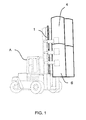
- FIG. 1 schematically shows a typical forklift used for moving bulk goods
- FIGS. 2 and 3 schematically show a solution of the invention for the identification of roll-like bulk goods
- FIG. 4 schematically shows a radio frequency identification device to be attached to roll-like bulk goods
- FIG. 5 schematically shows a second radio frequency identification device to be attached to roll-like bulk goods.
- FIG. 1 schematically shows a typical forklift A that is used for moving bulk goods and whose draw beam is provided with a reader antenna 1 described in the invention.
- FIGS. 2 and 3 schematically show a solution of the invention for the identification of roll-like bulk goods.
- the reader antenna 1 is composed of one or more antenna arrays 2 arranged to form a vector. Controlling the feeds of the antenna arrays allows the radiation midpoint 3 of the reader antenna 1 to shift along the axis of the reader antenna 1 in the direction of the vector. This allows a radio frequency identification device 7 in bulk goods 4 to be read with a radiation beam 5 directed from the shortest possible distance. The radiation beam 5 is perpendicular to the surface of the bulk goods 4 , thus eliminating reflections and signal distortion.
- an identification system changes the feeds of the antenna arrays 2 of the reader antenna 1 such that the radiation midpoint 3 shifts to an ideal point on the axis of the reader antenna 1 for identifying the bulk goods 6 .
- Other solutions that deviate from what was described above are also feasible in the invention. Consequently, the angle of the radiation beam 5 with respect to the reader antenna 1 may deviate from perpendicular or it may vary.
- FIG. 4 schematically shows a radio frequency identification device 12 to be arranged in bulk goods, preferably roll-like bulk goods.
- the radio frequency identification device is arranged in a plug to be placed in an inner paper roll core.
- a stopper or plug 11 made from plastic, wood or the like insulating material provides the body of the radio frequency identification stopper of the roll, and said radio frequency identification device 12 and for example four radiating microstrip antenna elements 13 are arranged therein.
- the radio frequency identification stopper 11 of the roll is arranged in an inner core 15 of a paper roll 14 .
- the figure also shows an end cover 16 and a wrapper cover 17 for protecting the roll.
- the radio frequency identification device 12 Upon identification of the roll, wherein the radio frequency identification stopper 11 is arranged, with the reader 1 composed of one or more antenna arrays as shown in FIGS. 1, 2 and 3 , the radio frequency identification device 12 replies to the reader 1 by means of the radiating microstrip antenna element 13 that provides the best possible connection.
- the use of said microstrip antenna elements 13 in the radio frequency identification stopper 11 of the roll allows the transmission of the radio frequency identification device 12 to be amplified and directed, thus improving the reliability of the identification.
- FIG. 5 schematically shows a second radio frequency identification device 22 to be attached to a roll.
- the radio frequency identification device 22 and one or more radiating elements are arranged in the end cover of a paper roll by way of example.
- the identification device and the radiating elements may be arranged in end covers of rolls used in paper industry such that they do not perceivably change the structure and appearance of the end covers.
- An end cover 21 of cardboard or the like constitutes the body of the radio frequency identification end cover of the paper roll.
- the end cover 21 is provided with the radio frequency identification device 22 , to which for example three radiating antenna elements 23 are coupled. These radiating antenna elements may be based on a Yagi, microstrip, wire, meander or other directional antenna structure well known to a person skilled in the art.
- the radio frequency identification end cover 21 of the paper roll is arranged to protect the end of a paper roll 24 .
- the paper roll is covered with a wrapper cover 25 .
- the radio frequency identification device 22 Upon identification of the roll 24 , wherein the radio frequency identification end cover 21 is arranged, with the reader 1 composed of one or more antenna arrays as shown in FIGS. 1, 2 and 3 , the radio frequency identification device 22 replies to the reader 1 by means of the radiating antenna element 23 that provides the best possible connection.
- the use of said Yagi antenna elements 23 allows the transmission of the radio frequency identification device 22 to be amplified, thus improving the reliability of the identification.
- radio frequency identification device 22 and one or more radiating elements 23 may be connected as a separate component to the end structure of the paper roll.
Abstract
In a method for identifying bulk goods from a radio frequency identification device on the bulk goods with a radio frequency reader antenna a radiation midpoint of the radio frequency reader antenna is moved along the radio frequency reader antenna and radiation from the radio frequency identification device is directed toward the radio frequency reader antenna.
Description
The invention relates to a method for the identification of bulk goods, preferably the identification of roll-like bulk goods, in which method a radio frequency reader antenna is used to identify a radio frequency identification device arranged in the bulk goods.
The invention further relates to an apparatus for the identification of bulk goods, preferably the identification of roll-like bulk goods, the apparatus comprising a radio frequency reader and a radio frequency identification device arranged in the bulk goods.
Known systems for the identification of bulk goods use optical identification methods, such as a bar code or a printed number series. U.S. Pat. No. 4,463,251 discloses a method for the identification of paper rolls, based on optical reading of a code marked at the end of the roll by means of a laser beam, for example. However, optical methods require a sufficient level of illumination. Furthermore, tags are susceptible to getting dirty, being chafed and wear, resulting in impaired identification. Optical identification systems also require a direct and completely unobstructed visual contact between the object and the reader, preventing identification from every direction.
Radio frequency identification systems are also used in the identification of bulk goods, wherein an identification device including a code enabling individualization is arranged in the bulk goods to be identified, and the code included in the identification device is read with a special reader. Such identification systems are disclosed in PCT publications WO 99/50788 and WO 00/16286.
In radio frequency identification systems, data is transferred between an identification device and a reader wirelessly by means of electromagnetic waves. Antenna solutions, in both the identification device and the reader, are crucial to the performance of radio frequency identification systems. According to their operation frequency, these radio frequency identification systems are dividable into low frequency and high frequency systems. In low frequency systems, a magnetic field is used in the coupling between the identification device and the reader, and various loop solutions are used as antennas. in low frequency systems, the reading distance is short and the reading distance depends on the areas of the antenna coils and their mutual positions. In high frequency systems, an electric field is used in the coupling, and the antennas used are usually dipole, folded dipole or microstrip antennas. Out of these, dipole and folded dipole antennas are omnidirectional, whereas a microstrip antenna is directional. in high frequency systems, the identification device is either active or passive. Active identification devices comprise a radio transmitter and a battery, whereas passive systems use the energy obtained from the reader. In high frequency systems, the reading distance is longer than in low frequency systems.
As was mentioned above, antennas, which are used for data transfer between an identification device and a reader, are crucial to the performance of radio frequency identification systems. The strength of the coupling between the antennas is affected by the alignment between the antennas, the radiating properties of individual antennas and the distance between the antennas.
Known reader antennas in radio frequency identification systems use a non-directional or fixedly aligned radiation beam or the radiation beam is directed from one point. These systems do not efficiently utilize the properties of the antennas. The problem in a non-directional reader antenna is the loss of transmitted power in directions that are useless for identification. In fixedly directed reader antennas, the tag may be outside the radiation beam of the reader antenna or the object to be identified may be larger than the reading range of the reader antenna. If the radiation beam is directed from one point, the reflection of the radiation emitted from the antenna from the boundary surfaces of the object to be identified interferes with the identification. This reflection occurs particularly when the incidence angle of the radiation deviates a lot from the perpendicular of the boundary surface. Furthermore, the distance between the identification device attached to the object and the reader antenna increases particularly at the edges of the reading range. This increases and attenuates the distance traveled by the radiation in the medium more compared with perpendicular alignment. For example, in a passive system utilizing backscattering, well known to a person skilled in the art, doubling the reading distance increases the attenuation to 16-fold. Furthermore, the boundary surfaces of the mediums cause diffraction as the signal penetrates them at an angle different from that of the perpendicular of the surface. This is one of the reasons why reasonably priced radio frequency identification systems have not been used in the logistics of for example paper rolls.
In the identification of bulk goods, the position of the object to be identified cannot usually be determined or predicted; instead, the radiation maximum of the antenna of the identification device attached to the object may face away from the reader antenna or the polarization levels of the antennas may be perpendicular to each other. The distance between the antennas may also be long or there may be material through which the radio waves have to propagate.
The dipole and folded dipole antennas generally used in radio frequency identification devices are usually omnidirectional, i.e. they emit electromagnetic radiation in all directions. However, these antenna types have low amplification. Furthermore, the frequency bands used by radio frequency identification devices have an officially regulated highest permitted transmission power, i.e. directional antenna structures can be used for improving the transmission of an identification device, if required. The use of directional, i.e. amplifying antenna structures, such as a microstrip antenna or an antenna array, allows the electromagnetic radiation power transmitted by the antenna to be directed more efficiently in the desired direction. This improves the coupling between the identification device and the reader antennas in the direction of the maximum of the radiation beam of the directional antenna compared with omnidirectional antennas, whereas the coupling is weaker outside the radiation beam than with omnidirectional antennas.
Roll-like bulk goods, such as paper or cardboard rolls, have to be identified always when the roll is handled at a factory, warehouse, when loading a conveyer chain or at the warehouse of a printing house. A roll is identified in a controlled situation, wherein the position of the roll with respect to its cylinder axis is known, i.e. the roll is either in a vertical or in a horizontal position. As far as the antenna of the identification device is concerned, this means that the polarization plane of the antenna is known. In contrast, the position angle of the roll around the cylinder axis is not known. In other words, when the identification device to be arranged in the roll uses a directional antenna element, the direction of the maximum of the antenna radiation beam is not known. If an identification device arranged on the surface of the roll is used in this kind of a situation, in the worst case the identification device is on the opposite side of the roll and the direction of the radiation beam of the antenna of the identification device is opposite to the direction from which the reader makes the identification. This means that reliable identification is very unlikely in such a situation.
The object of the invention is to provide a method and an apparatus for avoiding the drawbacks of known solutions and for achieving simpler and better identification of bulk goods, preferably roll-like bulk goods, than previously.
The method of the invention is characterized in that the radiation midpoint of a directed radiation beam of the radio frequency/reader is moving and said midpoint is used for perpendicular identification of an object to be identified, and that the radio frequency identification device arranged in the bulk goods uses an intelligent algorithm to direct the radiation beam of its antenna elements towards the radio frequency transmitter/reader.
The apparatus of the invention is characterized in that the apparatus comprises a radio frequency transmitter/reader, the radiation midpoint of the directed radiation beam of the antenna of which is arranged to move to perpendicularly identify an object to be identified, and a radio frequency identification device arranged in the bulk goods and arranged to use an intelligent algorithm to direct the radiation beam of its antennas towards the radio frequency transmitter/reader.
It is an essential idea of the invention that since the directed radiation beam of the reader antenna that has a moving radiation midpoint performs a perpendicular identification of the identification device arranged in a roll, and the identification device arranged in the roll uses an intelligent algorithm to direct the radiation beam of the antennas towards the reader antenna, the distance between the reader antenna and the identification device arranged in the roll always remains as short as possible. This reduces signal distortion and interfering reflections of the medium at the boundary surfaces. Since the distance is minimized and there are few interfering reflections and signal distortions, the power level required for a reliable radio link is significantly lower. Furthermore, it is an essential idea of a preferred embodiment of the invention that amplifying antenna arrays or some such system is used to create the radiation beam. This significantly improves the radio frequency connection between the reader and the object to be identified, allows the reading range to be protected against spurious signals from outside the range and a reliable identification under all circumstances and situations at every stage of the logistics chain of the object to be identified.
In accordance with the invention, this aim is achieved by using one or more radiating elements in the reader antenna and changing the feed of the elements to allow the radiation midpoint of the antenna to shift on the axis of the antenna in order for the distance between the reader antenna and the identification device arranged in the object to be identified to remain as short as possible. Furthermore, the direction of the radiation beam can be changed such that, together with said distance between the reader antenna and the identification device of the object to be identified, the incidence angle of the radiation with respect to the boundary surface of the object to be identified is optimized. A radio frequency identification device provided with a plurality of directional antenna elements is used in a roll. The antenna elements are arranged around the cylinder axis of the roll such that they allow the transmission of the identification device to be transmitted in the desired direction on a plane perpendicular to the cylinder axis and an as advantageous a distance to the reader antenna as possible. When the radiating element used is for example one microstrip antenna the width of whose half power radiation beam is for example 90 degrees, at least four such elements are needed to cover the full 360 degrees, from which the identification may be performed with the reader. The simultaneous use of a plurality of antenna elements in the same way as an antenna array also allows the transmission from the identification device to be transmitted in the desired direction. The choice of reader and, consequently, transmission direction is performed in the identification device by means of an intelligent algorithm or some such method. The intelligent algorithm of the identification device identifies the direction from which the transmission of the reader is coming and transmits its transmission in the same direction.
It is an advantage of the invention that it allows reliable identification of roll-like bulk goods in a dark, dusty and misty environment. Identification may also be performed from any direction. The cover paper of the roll may also get dirty, wear or be chafed without the identification being impaired.
The invention will be described in greater in the accompanying drawings, in which
FIG. 1 schematically shows a typical forklift used for moving bulk goods,
FIGS. 2 and 3 schematically show a solution of the invention for the identification of roll-like bulk goods,
FIG. 4 schematically shows a radio frequency identification device to be attached to roll-like bulk goods, and
FIG. 5 schematically shows a second radio frequency identification device to be attached to roll-like bulk goods.
FIG. 1 schematically shows a typical forklift A that is used for moving bulk goods and whose draw beam is provided with a reader antenna 1 described in the invention.
FIGS. 2 and 3 schematically show a solution of the invention for the identification of roll-like bulk goods. In the figures, the reader antenna 1 is composed of one or more antenna arrays 2 arranged to form a vector. Controlling the feeds of the antenna arrays allows the radiation midpoint 3 of the reader antenna 1 to shift along the axis of the reader antenna 1 in the direction of the vector. This allows a radio frequency identification device 7 in bulk goods 4 to be read with a radiation beam 5 directed from the shortest possible distance. The radiation beam 5 is perpendicular to the surface of the bulk goods 4, thus eliminating reflections and signal distortion. When the radio frequency identification device is read from bulk goods 6, an identification system changes the feeds of the antenna arrays 2 of the reader antenna 1 such that the radiation midpoint 3 shifts to an ideal point on the axis of the reader antenna 1 for identifying the bulk goods 6. Other solutions that deviate from what was described above are also feasible in the invention. Consequently, the angle of the radiation beam 5 with respect to the reader antenna 1 may deviate from perpendicular or it may vary.
FIG. 4 schematically shows a radio frequency identification device 12 to be arranged in bulk goods, preferably roll-like bulk goods. The radio frequency identification device is arranged in a plug to be placed in an inner paper roll core. A stopper or plug 11, made from plastic, wood or the like insulating material provides the body of the radio frequency identification stopper of the roll, and said radio frequency identification device 12 and for example four radiating microstrip antenna elements 13 are arranged therein. The radio frequency identification stopper 11 of the roll is arranged in an inner core 15 of a paper roll 14. The figure also shows an end cover 16 and a wrapper cover 17 for protecting the roll.
Upon identification of the roll, wherein the radio frequency identification stopper 11 is arranged, with the reader 1 composed of one or more antenna arrays as shown in FIGS. 1, 2 and 3, the radio frequency identification device 12 replies to the reader 1 by means of the radiating microstrip antenna element 13 that provides the best possible connection. The use of said microstrip antenna elements 13 in the radio frequency identification stopper 11 of the roll allows the transmission of the radio frequency identification device 12 to be amplified and directed, thus improving the reliability of the identification.
FIG. 5 schematically shows a second radio frequency identification device 22 to be attached to a roll. Herein, the radio frequency identification device 22 and one or more radiating elements are arranged in the end cover of a paper roll by way of example. The identification device and the radiating elements may be arranged in end covers of rolls used in paper industry such that they do not perceivably change the structure and appearance of the end covers. An end cover 21 of cardboard or the like constitutes the body of the radio frequency identification end cover of the paper roll. The end cover 21 is provided with the radio frequency identification device 22, to which for example three radiating antenna elements 23 are coupled. These radiating antenna elements may be based on a Yagi, microstrip, wire, meander or other directional antenna structure well known to a person skilled in the art. The radio frequency identification end cover 21 of the paper roll is arranged to protect the end of a paper roll 24. In addition to this, the paper roll is covered with a wrapper cover 25.
Upon identification of the roll 24, wherein the radio frequency identification end cover 21 is arranged, with the reader 1 composed of one or more antenna arrays as shown in FIGS. 1, 2 and 3, the radio frequency identification device 22 replies to the reader 1 by means of the radiating antenna element 23 that provides the best possible connection. The use of said Yagi antenna elements 23, for example, allows the transmission of the radio frequency identification device 22 to be amplified, thus improving the reliability of the identification.
The drawings and the related description are only intended to illustrate the inventive idea. The details of the invention may vary within the scope of the claims. Accordingly, the radio frequency identification device 22 and one or more radiating elements 23 may be connected as a separate component to the end structure of the paper roll.
Claims (15)
1. In a method for identification of bulk goods, in which method a radio frequency transmitter/reader (1) is used to identify a radio frequency identification device (12, 22) arranged in the bulk goods, the improvements comprising:
moving a radiation midpoint (3) of a directed radiation beam (5) of the radio frequency transmitter/reader (1);
using said midpoint (3) for perpendicular identification of an object to be identified; and
directing radiation of radiating antenna elements (13, 23) with the radio frequency identification device (12, 22) towards the radio frequency transmitter/reader (1).
2. A method as claimed in claim 1 , characterized in that the intelligent algorithm of the radio frequency identification device (12, 22) is used to identify the direction from which the transmission of the radio frequency transmitter/reader (1) is coming, and the intelligent algorithm is used to transmit a new transmission back in said direction.
3. A method as claimed in claim 1 , characterized in that the feed of the radio frequency transmitter/reader (1) is changed to shift the radiation midpoint (3) on the axis of an antenna of the radio frequency transmitter/reader (1).
4. A method as claimed in claim 1 , characterized in that the direction of the radiation beam (5) is changed with respect to the axis of an antenna of the radio frequency transmitter/reader (1).
5. A method as claimed in claim 1 , characterized in that the feed of the radio frequency transmitter/reader (1) is changed to shift the radiation midpoint (3) on the axis of an antenna of the radio frequency transmitter/reader (1), and amplifying antenna arrays or the like system is used for creating the radiation beam (5).
6. An apparatus for identification of bulk goods, the apparatus comprising a radio frequency transmitter/reader (1) and a radio frequency identification device (12, 22) arranged in the bulk goods, characterized in that a radiation midpoint (3) of a directed radiating beam (5) of the radio frequency transmitter/reader is arranged to move, that said radiation midpoint (3) is arranged to perpendicularly identify an object to be identified, and that the radio frequency identification device (12, 22) arranged in the bulk goods directs radiation of radiating antenna elements (13, 23) towards the radio frequency transmitter/reader (1).
7. An apparatus as claimed in claim 6 , characterized in that the distance between the radio frequency transmitter/reader (1) and the radio frequency identification device (12, 22) in the object to be identified remains as short as possible.
8. An apparatus as claimed in claim 6 , characterized in that at least one radiating antenna element (13, 23) is arranged in the radio frequency identification device (12, 22) in the object to be identified.
9. An apparatus as claimed in claim 8 , characterized in that the radiating antenna elements (13, 23) of the radio frequency identification device (12, 22) in the object to be identified are arranged around the cylinder axis of the roll-like bulk goods.
10. An apparatus as claimed in claim 6 , characterized in that the angle of the radiation beam (5) of the radio frequency transmitter/reader (1) with respect to an antenna thereof is arranged fixed or variable.
11. An apparatus as claimed in claim 6 , characterized in that an antenna or the antenna array of the radio frequency transmitter/reader is arranged omnidirectional, directional or amplifying.
12. An apparatus as claimed in claim 6 , characterized in that the direction of the radiation beam (5) is changed with respect to the axis of an antenna of the radio frequency transmitter/reader (1) and the radio frequency identification device (12, 22) is arranged passive or active.
13. An apparatus as claimed in claim 6 , characterized in that the radiating antenna element (13, 23) of the radio frequency identification device (12, 22) is arranged omnidirectional, directional or amplifying.
14. In a method for identifying bulk goods from a radio frequency identification device (12, 22) on the bulk goods with a radio frequency transmitter/reader (1), the improvements comprising:
moving a radiation midpoint (3) of the radio frequency reader antenna along the radio frequency transmitter/reader and
directing radiation with the radio frequency identification device toward the radio frequency transmitter/reader.
15. The method as claimed in claim 14 , wherein the bulk goods are roll-like, whereby to show an axis, the radio frequency transmitter/reader has an axis arranged generally parallel to the axis shown by the roll-like bulk goods, and the moving of the radiation midpoint is along the axis of the radio frequency transmitter/reader.
Applications Claiming Priority (6)
| Application Number | Priority Date | Filing Date | Title |
|---|---|---|---|
| FI20000763A FI20000763A0 (en) | 2000-04-03 | 2000-04-03 | The reader antenna |
| FI20000762 | 2000-04-03 | ||
| FI20000764A FI20000764A0 (en) | 2000-04-03 | 2000-04-03 | Radio frequency identifier plug for paper roll |
| FI20000763 | 2000-04-03 | ||
| FI20000762A FI20000762A0 (en) | 2000-04-03 | 2000-04-03 | Paper roll radio frequency tag protection |
| FI20000764 | 2000-04-03 |
Publications (2)
| Publication Number | Publication Date |
|---|---|
| US20010038333A1 US20010038333A1 (en) | 2001-11-08 |
| US6819243B2 true US6819243B2 (en) | 2004-11-16 |
Family
ID=27241779
Family Applications (1)
| Application Number | Title | Priority Date | Filing Date |
|---|---|---|---|
| US09/824,522 Expired - Fee Related US6819243B2 (en) | 2000-04-03 | 2001-04-02 | Method and apparatus for identifying bulk goods, preferably roll-like bulk goods |
Country Status (1)
| Country | Link |
|---|---|
| US (1) | US6819243B2 (en) |
Cited By (7)
| Publication number | Priority date | Publication date | Assignee | Title |
|---|---|---|---|---|
| US20040049428A1 (en) * | 2002-09-05 | 2004-03-11 | Soehnlen John Pius | Wireless environmental sensing in packaging applications |
| US20040102869A1 (en) * | 2002-11-26 | 2004-05-27 | Andersen Scott Paul | System and method for tracking inventory |
| US20040102870A1 (en) * | 2002-11-26 | 2004-05-27 | Andersen Scott Paul | RFID enabled paper rolls and system and method for tracking inventory |
| US20060058913A1 (en) * | 2002-11-26 | 2006-03-16 | Andersen Scott P | Inventory tracking |
| US20070096909A1 (en) * | 2005-10-28 | 2007-05-03 | Matthew Lally | Interactive networking device |
| US20090177315A1 (en) * | 2007-12-21 | 2009-07-09 | Georgia-Pacific Consumer Products Lp | Product, Dispenser and Method of Dispensing Product |
| US8833691B1 (en) | 2007-12-21 | 2014-09-16 | Georgia-Pacific Consumer Products Lp | Product, dispenser and method of dispensing product |
Families Citing this family (6)
| Publication number | Priority date | Publication date | Assignee | Title |
|---|---|---|---|---|
| US7398054B2 (en) * | 2003-08-29 | 2008-07-08 | Zih Corp. | Spatially selective UHF near field microstrip coupler device and RFID systems using device |
| US8596532B2 (en) | 2004-06-10 | 2013-12-03 | Zih Corp. | Apparatus and method for communicating with an RFID transponder |
| FR2871968B1 (en) * | 2004-06-16 | 2006-09-08 | Gemplus Sa | SYNCHRONOUS PHASE CONTACTLESS DEMODULATION METHOD, DEMODULATOR AND READER |
| AU2007286652B2 (en) * | 2006-08-23 | 2011-05-26 | Hunter Douglas Inc. | Dual control system and method |
| TWI431553B (en) * | 2011-12-05 | 2014-03-21 | Claridy Solutions Inc | Radio Frequency Identification Library Management Security Gate |
| NL2008946C2 (en) * | 2012-06-06 | 2013-12-09 | Berend Breman | CYLINDER-MADE PRODUCT, RECORDING DEVICE, VEHICLE AND METHOD. |
Citations (18)
| Publication number | Priority date | Publication date | Assignee | Title |
|---|---|---|---|---|
| US4463251A (en) * | 1981-06-17 | 1984-07-31 | Oy Wartsila A.B. | Method and means for the identification of a roll |
| US4654658A (en) * | 1984-08-03 | 1987-03-31 | Walton Charles A | Identification system with vector phase angle detection |
| US4990921A (en) | 1987-05-01 | 1991-02-05 | Sundstrand Data Control, Inc. | Multi-mode microwave landing system |
| FR2697680A1 (en) | 1992-11-03 | 1994-05-06 | Thomson Csf Radant | Anti-Collision radar antenna with electronic scanning for motor vehicle - has array of openings in plate fed by waveguides formed by second plate forming steerable beam |
| US5354976A (en) * | 1992-04-10 | 1994-10-11 | Valmet Paper Machinery Inc. | Method for identification of rolls and a device for its accomplishment |
| US5604715A (en) | 1994-06-21 | 1997-02-18 | Aman; James A. | Automated lumber unit trucking system |
| US5719586A (en) | 1992-05-15 | 1998-02-17 | Micron Communications, Inc. | Spherical antenna pattern(s) from antenna(s) arranged in a two-dimensional plane for use in RFID tags and labels |
| US5821524A (en) * | 1996-08-19 | 1998-10-13 | Pharmacopeia, Inc. | Method and apparatus for reading bar coded tubular members such as cylindrical vials |
| GB2328320A (en) | 1997-08-04 | 1999-02-17 | Samsung Electronics Co Ltd | Adaptive phased array antenna with weight memory |
| WO1999050788A1 (en) | 1998-03-27 | 1999-10-07 | Baumer Ident Gmbh | Device for marking objects |
| US5971281A (en) * | 1996-08-26 | 1999-10-26 | Storage Technology Corporation | Method for storing multiple logical data volumes on a single physical volume utilizing writable labels and physical volume produced thereby |
| US6008727A (en) * | 1998-09-10 | 1999-12-28 | Xerox Corporation | Selectively enabled electronic tags |
| WO2000016286A1 (en) | 1998-09-11 | 2000-03-23 | Motorola Inc. | Radio frequency identification tag apparatus and related method |
| WO2000026991A1 (en) | 1998-11-04 | 2000-05-11 | Checkpoint Systems, Inc. | Rotating field antenna with a magnetically coupled quadrature loop |
| US6069564A (en) * | 1998-09-08 | 2000-05-30 | Hatano; Richard | Multi-directional RFID antenna |
| US6195007B1 (en) * | 1998-09-04 | 2001-02-27 | Sony Corporation | Recording medium handling apparatus |
| US6232870B1 (en) * | 1998-08-14 | 2001-05-15 | 3M Innovative Properties Company | Applications for radio frequency identification systems |
| US6453808B1 (en) * | 1998-03-02 | 2002-09-24 | Valmet Corporation | Method and apparatus for marking paper, board and cellulose web rolls |
-
2001
- 2001-04-02 US US09/824,522 patent/US6819243B2/en not_active Expired - Fee Related
Patent Citations (18)
| Publication number | Priority date | Publication date | Assignee | Title |
|---|---|---|---|---|
| US4463251A (en) * | 1981-06-17 | 1984-07-31 | Oy Wartsila A.B. | Method and means for the identification of a roll |
| US4654658A (en) * | 1984-08-03 | 1987-03-31 | Walton Charles A | Identification system with vector phase angle detection |
| US4990921A (en) | 1987-05-01 | 1991-02-05 | Sundstrand Data Control, Inc. | Multi-mode microwave landing system |
| US5354976A (en) * | 1992-04-10 | 1994-10-11 | Valmet Paper Machinery Inc. | Method for identification of rolls and a device for its accomplishment |
| US5719586A (en) | 1992-05-15 | 1998-02-17 | Micron Communications, Inc. | Spherical antenna pattern(s) from antenna(s) arranged in a two-dimensional plane for use in RFID tags and labels |
| FR2697680A1 (en) | 1992-11-03 | 1994-05-06 | Thomson Csf Radant | Anti-Collision radar antenna with electronic scanning for motor vehicle - has array of openings in plate fed by waveguides formed by second plate forming steerable beam |
| US5604715A (en) | 1994-06-21 | 1997-02-18 | Aman; James A. | Automated lumber unit trucking system |
| US5821524A (en) * | 1996-08-19 | 1998-10-13 | Pharmacopeia, Inc. | Method and apparatus for reading bar coded tubular members such as cylindrical vials |
| US5971281A (en) * | 1996-08-26 | 1999-10-26 | Storage Technology Corporation | Method for storing multiple logical data volumes on a single physical volume utilizing writable labels and physical volume produced thereby |
| GB2328320A (en) | 1997-08-04 | 1999-02-17 | Samsung Electronics Co Ltd | Adaptive phased array antenna with weight memory |
| US6453808B1 (en) * | 1998-03-02 | 2002-09-24 | Valmet Corporation | Method and apparatus for marking paper, board and cellulose web rolls |
| WO1999050788A1 (en) | 1998-03-27 | 1999-10-07 | Baumer Ident Gmbh | Device for marking objects |
| US6232870B1 (en) * | 1998-08-14 | 2001-05-15 | 3M Innovative Properties Company | Applications for radio frequency identification systems |
| US6195007B1 (en) * | 1998-09-04 | 2001-02-27 | Sony Corporation | Recording medium handling apparatus |
| US6069564A (en) * | 1998-09-08 | 2000-05-30 | Hatano; Richard | Multi-directional RFID antenna |
| US6008727A (en) * | 1998-09-10 | 1999-12-28 | Xerox Corporation | Selectively enabled electronic tags |
| WO2000016286A1 (en) | 1998-09-11 | 2000-03-23 | Motorola Inc. | Radio frequency identification tag apparatus and related method |
| WO2000026991A1 (en) | 1998-11-04 | 2000-05-11 | Checkpoint Systems, Inc. | Rotating field antenna with a magnetically coupled quadrature loop |
Cited By (14)
| Publication number | Priority date | Publication date | Assignee | Title |
|---|---|---|---|---|
| US20040049428A1 (en) * | 2002-09-05 | 2004-03-11 | Soehnlen John Pius | Wireless environmental sensing in packaging applications |
| US7151979B2 (en) * | 2002-11-26 | 2006-12-19 | International Paper Company | System and method for tracking inventory |
| US20040102870A1 (en) * | 2002-11-26 | 2004-05-27 | Andersen Scott Paul | RFID enabled paper rolls and system and method for tracking inventory |
| US20060036346A1 (en) * | 2002-11-26 | 2006-02-16 | Andersen Scott P | System and method for tracking inventory |
| US20060058913A1 (en) * | 2002-11-26 | 2006-03-16 | Andersen Scott P | Inventory tracking |
| US20040102869A1 (en) * | 2002-11-26 | 2004-05-27 | Andersen Scott Paul | System and method for tracking inventory |
| US7818088B2 (en) * | 2002-11-26 | 2010-10-19 | Rush Tracking Systems, Llc | System and method for tracking inventory |
| US8295974B2 (en) | 2002-11-26 | 2012-10-23 | Rush Tracking Systems, Llc | System and method for tracking inventory |
| US8774960B2 (en) | 2002-11-26 | 2014-07-08 | Totaltrax, Inc. | System and method for tracking inventory |
| US20060220872A1 (en) * | 2005-03-01 | 2006-10-05 | Brown Mark A | Mounting bracket |
| US20070096909A1 (en) * | 2005-10-28 | 2007-05-03 | Matthew Lally | Interactive networking device |
| US20090177315A1 (en) * | 2007-12-21 | 2009-07-09 | Georgia-Pacific Consumer Products Lp | Product, Dispenser and Method of Dispensing Product |
| US8165716B1 (en) | 2007-12-21 | 2012-04-24 | Georgia-Pacific Consumer Products Lp | Product, dispenser and method of dispensing product |
| US8833691B1 (en) | 2007-12-21 | 2014-09-16 | Georgia-Pacific Consumer Products Lp | Product, dispenser and method of dispensing product |
Also Published As
| Publication number | Publication date |
|---|---|
| US20010038333A1 (en) | 2001-11-08 |
Similar Documents
| Publication | Publication Date | Title |
|---|---|---|
| US6819243B2 (en) | Method and apparatus for identifying bulk goods, preferably roll-like bulk goods | |
| ES2366915T3 (en) | RADIO FREQUENCY IDENTIFICATION DEVICES TO ALLOW THE READING OF ITEMS OUTSIDE THE VISUAL LINE. | |
| US7586410B2 (en) | RFID UHF stripline coupler | |
| US9994043B2 (en) | Near field coupling devices and associated systems and methods | |
| CA2219099C (en) | Antenna array in an rfid system | |
| US7262701B1 (en) | Antenna structures for RFID devices | |
| JP5426573B2 (en) | Combination security tag and method using peripheral RFID antenna surrounding EAS element | |
| US7714791B2 (en) | Antenna with improved illumination efficiency | |
| US20060220872A1 (en) | Mounting bracket | |
| KR20090084824A (en) | Radio frequency identification system | |
| JP2009516944A (en) | Robust RFID antenna with low reflection loss | |
| US8866616B2 (en) | RFID tag having antenna with co-planar radiation pattern | |
| KR20080024064A (en) | Rf tag reader and method | |
| US7420512B2 (en) | Antenna system | |
| US7839287B2 (en) | Near-field miniature coupler | |
| JP2023114292A (en) | RF tag system | |
| JP6647646B1 (en) | Electronic tag reader | |
| AU2014200642A1 (en) | Combination security tag using a perimeter RFID antenna surrounding an EAS element and method thereof |
Legal Events
| Date | Code | Title | Description |
|---|---|---|---|
| CC | Certificate of correction | ||
| REMI | Maintenance fee reminder mailed | ||
| LAPS | Lapse for failure to pay maintenance fees | ||
| STCH | Information on status: patent discontinuation |
Free format text: PATENT EXPIRED DUE TO NONPAYMENT OF MAINTENANCE FEES UNDER 37 CFR 1.362 |
|
| FP | Lapsed due to failure to pay maintenance fee |
Effective date: 20081116 |