US6823243B2 - Open-ended scan analysis with auto-identification of multi-platform gas analyzers - Google Patents
Open-ended scan analysis with auto-identification of multi-platform gas analyzers Download PDFInfo
- Publication number
- US6823243B2 US6823243B2 US10/319,579 US31957902A US6823243B2 US 6823243 B2 US6823243 B2 US 6823243B2 US 31957902 A US31957902 A US 31957902A US 6823243 B2 US6823243 B2 US 6823243B2
- Authority
- US
- United States
- Prior art keywords
- test instrument
- data
- acquisition device
- subsystem
- data acquisition
- Prior art date
- Legal status (The legal status is an assumption and is not a legal conclusion. Google has not performed a legal analysis and makes no representation as to the accuracy of the status listed.)
- Expired - Lifetime
Links
- 238000004458 analytical method Methods 0.000 title description 3
- 238000012360 testing method Methods 0.000 claims abstract description 111
- 238000004891 communication Methods 0.000 claims abstract description 29
- 238000000034 method Methods 0.000 claims description 30
- 230000008569 process Effects 0.000 claims description 21
- IJGRMHOSHXDMSA-UHFFFAOYSA-N Atomic nitrogen Chemical compound N#N IJGRMHOSHXDMSA-UHFFFAOYSA-N 0.000 claims description 4
- 238000012544 monitoring process Methods 0.000 claims description 4
- 238000012545 processing Methods 0.000 claims description 3
- 229910052757 nitrogen Inorganic materials 0.000 claims description 2
- 230000003111 delayed effect Effects 0.000 abstract description 2
- 230000001360 synchronised effect Effects 0.000 abstract 1
- 239000007789 gas Substances 0.000 description 29
- 230000006870 function Effects 0.000 description 10
- 238000013461 design Methods 0.000 description 7
- 238000007726 management method Methods 0.000 description 5
- 230000004913 activation Effects 0.000 description 3
- 238000010276 construction Methods 0.000 description 3
- 238000005259 measurement Methods 0.000 description 3
- 230000003068 static effect Effects 0.000 description 3
- 238000010586 diagram Methods 0.000 description 2
- 238000002372 labelling Methods 0.000 description 2
- 238000012986 modification Methods 0.000 description 2
- 230000004048 modification Effects 0.000 description 2
- 241000721701 Lynx Species 0.000 description 1
- 230000002159 abnormal effect Effects 0.000 description 1
- 230000009118 appropriate response Effects 0.000 description 1
- 238000012512 characterization method Methods 0.000 description 1
- 238000010924 continuous production Methods 0.000 description 1
- 238000012937 correction Methods 0.000 description 1
- 238000013523 data management Methods 0.000 description 1
- 230000002708 enhancing effect Effects 0.000 description 1
- 238000009434 installation Methods 0.000 description 1
- 238000012423 maintenance Methods 0.000 description 1
- 230000014759 maintenance of location Effects 0.000 description 1
- 238000004519 manufacturing process Methods 0.000 description 1
- 230000013011 mating Effects 0.000 description 1
- 229910052987 metal hydride Inorganic materials 0.000 description 1
- 230000002093 peripheral effect Effects 0.000 description 1
- 238000003825 pressing Methods 0.000 description 1
- 230000008439 repair process Effects 0.000 description 1
- 238000003860 storage Methods 0.000 description 1
- 230000001960 triggered effect Effects 0.000 description 1
- 238000013024 troubleshooting Methods 0.000 description 1
Images


Classifications
-
- G—PHYSICS
- G01—MEASURING; TESTING
- G01N—INVESTIGATING OR ANALYSING MATERIALS BY DETERMINING THEIR CHEMICAL OR PHYSICAL PROPERTIES
- G01N35/00—Automatic analysis not limited to methods or materials provided for in any single one of groups G01N1/00 - G01N33/00; Handling materials therefor
- G01N35/00584—Control arrangements for automatic analysers
- G01N35/00722—Communications; Identification
- G01N35/00871—Communications between instruments or with remote terminals
-
- G—PHYSICS
- G07—CHECKING-DEVICES
- G07C—TIME OR ATTENDANCE REGISTERS; REGISTERING OR INDICATING THE WORKING OF MACHINES; GENERATING RANDOM NUMBERS; VOTING OR LOTTERY APPARATUS; ARRANGEMENTS, SYSTEMS OR APPARATUS FOR CHECKING NOT PROVIDED FOR ELSEWHERE
- G07C5/00—Registering or indicating the working of vehicles
- G07C5/08—Registering or indicating performance data other than driving, working, idle, or waiting time, with or without registering driving, working, idle or waiting time
- G07C5/0841—Registering performance data
- G07C5/085—Registering performance data using electronic data carriers
-
- G—PHYSICS
- G01—MEASURING; TESTING
- G01N—INVESTIGATING OR ANALYSING MATERIALS BY DETERMINING THEIR CHEMICAL OR PHYSICAL PROPERTIES
- G01N1/00—Sampling; Preparing specimens for investigation
- G01N1/02—Devices for withdrawing samples
- G01N1/22—Devices for withdrawing samples in the gaseous state
- G01N1/2247—Sampling from a flowing stream of gas
- G01N1/2252—Sampling from a flowing stream of gas in a vehicle exhaust
Definitions
- the present invention relates generally to electronic test equipment. More particularly, the present invention relates to diagnostic and display apparatus for troubleshooting and repair of motor vehicles, to include interface with onboard motor vehicle control computers.
- Onboard control computers have become ubiquitous in motor vehicles, as safety, economy, and emissions requirements have continued to escalate, and conventional designs for reciprocating engines, friction braking systems, collision safety apparatus, and traction control devices have proven unequal to the requirements set out in law and the implicit demands of competitors' achievements.
- Successive generations of onboard control computers have acquired increasing data sensing and retention capability as the electronic art has advanced.
- Present external diagnostic and display apparatus known to those skilled in the art as Scan Tools, are commonly limited to reporting the data acquired by the onboard control computer itself.
- Scan Tools are commonly limited to reporting the data acquired by the onboard control computer itself.
- Increasingly subtle subsystem failures in automobiles overload the ability of maintenance technicians not simply to read the faults detected and stored by the computers themselves, but to combine those readings with peripheral measurements in order to allow a technician to identify faults and decide on corrective actions with both speed and accuracy.
- the present invention by enhancing the Scan Tool's ability to collect data from external test devices via data input ports, and by merging the additional data with data previously available from the onboard computer into a single display with fully coordinated timing, presents to the technician a more complete picture of the status of the motor vehicle under test.
- the present invention speeds setup and performance of testing in a cost-driven, time-critical environment.
- a test apparatus for acquiring and displaying motor vehicle data includes a scan interface subsystem permitting communication between the test apparatus and a motor vehicle onboard diagnostic (OBD) computer, an external device interface subsystem permitting communication between the test apparatus and additional data acquisition devices, and a display in communication with the scan interface and the external device interface component, where the display presents data from the scan interface and from additional data acquisition devices with which the external device interface component may be in communication.
- OBD onboard diagnostic
- the Scan Tool is enhanced through the provision of means whereby vehicle status data from multiple sources can be combined and displayed.
- the present invention provides means whereby fixed data elements from the vehicle's OBD computer, data from the OBD computer changing at any rate, fixed measurements from other data acquisition devices, and dynamic signals from other data acquisition devices can be gathered, scaled with respect to time delay, rate, and amplitude, then stored or displayed.
- the Scan Tool provides a method for acquiring and displaying motor vehicle diagnostic data that includes the steps of obtaining data from a computer on a motor vehicle, obtaining data from external test equipment, and displaying data from the computer on the motor vehicle and data from the external test equipment.
- FIG. 1 an oblique front view of a hand-held Scan Tool, illustrates placement of displays, controls, and ports of a preferred embodiment of the present invention.
- FIG. 2 an oblique rear view of the Scan Tool, illustrates connections to additional ports of a preferred embodiment of the present invention.
- FIG. 3 a view similar to FIG. 2, shows the Scan Tool with a representative Gas Analyzer fitted into a recess in its rear surface and mated to the connector therein.
- FIG. 4 provides a representative view of the Scan Tool's display, in which typical data items are presented and soft keys are shown, available for user activation.
- FIG. 5 is a block diagram showing the functional units of the present invention.
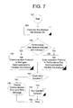
- FIG. 6 and FIG. 7 are summarized flowcharts illustrating the steps that may be followed in performance of the functions of the present invention, including and identifying new functions embodied in the present invention.
- a handheld interface unit 2 has a display panel 4 , a first button group 5 , and a second button group 6 .
- the shape of the preferred embodiment of the unit 2 is designed to provide large size to allow the display panel 4 to afford ease of viewing, while providing a handle 8 that allows typical users to grip the unit securely.
- the button group 5 in the preferred embodiment allows the bottom zone of the display to be assigned as needed as a row of up to four “soft keys” for changeable user interface options; alternative embodiments with any number of buttons and corresponding “soft keys” are possible.
- the button group 6 provides a set of switch closures independent of screen status, and serves as a primary user interface to the microprocessor-based Scan Tool.
- Ports shown in FIG. 1 are a first custom interface connector 10 for an OBD adapter, a serial port connector 12 , a USB port connector 14 , an Infrared Data Association (IrDA)/Hewlett-Packard (HP) Infrared connection 16 , a PCMCIA type 2 connector 18 and a smart card connector 20 .
- IrDA Infrared Data Association
- HP Hewlett-Packard
- FIG. 2 shows the rear panel of a preferred embodiment of the invention; in this view, a second custom interface connector, termed a hardware interface port, or HIP, 22 , is shown, which provides the Scan Tool with the capability of adapting functions from earlier designs to operate with the present invention.
- a Compact Flash® card connector 24 not visible, occupies a slot on another face of the preferred embodiment.
- the ports shown in the views above are representative of ports that could be included in a system design supporting the preferred embodiment of the present invention.
- the battery box cover 26 allows the apparatus to be powered from a built-in Nickel-Metal Hydride (NiMH) battery.
- NiMH Nickel-Metal Hydride
- the preferred design permits a power supply that can furnish the requisite direct-current (DC) voltage at sufficient amperage to be plugged into a power jack 28 , supporting in-unit recharging of the NiMH battery and allowing indefinite operating time.
- DC direct-current
- FIG. 3 shows the view of FIG. 2 with a typical Gas Analyzer 140 installed.
- a Gas Analyzer directly mating with the HIP connector 22 , may carry one of a variety of communications interfaces with which the inventive apparatus is compatible.
- Other Gas Analyzer modules that can function with the preferred embodiment may communicate with it through alternative ports, such as the serial port 12 , and may use other protocols than that used by the Gas Analyzer 140 .
- FIG. 4 illustrates the display of one embodiment, wherein a full-color display screen 30 has facility to present a plurality of time (horizontal axis) versus selected parameter (vertical axis) data events, as well as text information.
- the capability of the concept is illustrated by a first trace 32 that shows engine revolutions per minute (RPM) as a function of time during a particular test session, and a second trace 34 that shows exhaust gas concentration of oxides of nitrogen, the latter data having been acquired at a different time during the same test interval.
- the horizontal axis of the display shows a low-resolution section 36 and a high-resolution section 38 , which capability is a selectable function of the preferred embodiment.
- a first dashed line 40 indicates the exact point on the time axis that corresponds to a first text readout 42 , which provides a descriptive label, a value, and a unit reference; a first pair of minimum and maximum readings 44 is provided to establish a scale.
- the second trace 34 represents data from an external test device, which data is available after a fixed delay. The display is offset accordingly, allowing the two readings to be aligned in time.
- a second dashed line 46 indicates the sample time for a second text display 48 .
- a second scale indication 50 provides a second frame of reference.
- the display shows a plurality of additional test items in the form of text only, which can include labels 52 , data values 54 , and units 56 where relevant.
- the display further shows representative status information, such as a note 58 indicating the delay time for the gas sensor.
- a group of “soft” buttons 60 have functions dynamically defined, with activation for the immediate definitions of the button functions triggered through the buttons shown in FIG. 1 as item 6 .
- a slidebar 62 familiar to users of graphical user interface (GUI)-based operating systems such as Lynx®, Apple® OS9®, and Microsoft® Windows®, indicates the presence of and provides access to additional data not presently visible on the display.
- GUI graphical user interface
- FIG. 5 illustrates the electronic circuitry in block diagram form.
- a power-input subsystem 64 accepts available DC and converts it to the voltages needed for all other subsystems within the apparatus.
- a computational subsystem 66 that includes a central processing unit 68 , a dynamic data memory area 70 , a preprogrammed instruction memory area 72 , a reprogrammable instruction and data area 74 , an interface control unit 76 , a master clock 78 , and a watchdog timer 80 , performs analysis and control of all functions.
- a display subsystem 82 that includes a display screen 84 , a dedicated display voltage generator 86 , a backlight voltage generator 88 , a display interface unit 90 , a display image generator 92 , and a display driver 94 , accepts, stores, and displays data generated by the computational subsystem 66 .
- An external data interface unit 96 that includes a set of transceivers 98 and a dedicated data interface processor 100 receives digital data from installed external test instruments requiring such dedicated handshaking and presents this data to the computational subsystem 66 , which collates and processes that data. The external data interface unit 96 further transmits such digital handshaking and control data as the external test instruments may require in order to continue providing measurements.
- FIG. 6 shows one of the major elements included in the present invention.
- operation begins with basic initialization 102 .
- the call to the Vehicle Selection Front End Process 104 (VS Process) identifies the vehicle under test through a process combining user interface and data table lookup.
- VS Process 104 software will guide an operator through interpretation of the characters of the VIN, such as an “F” in the second position indicating a Ford or a “G” in the tenth position representing the year 1986. For each of several combinations of position and data value, the VS Process 104 permits the operator to compile a description of the vehicle under test.
- the operator can key in a vehicle identification number (VIN) and the Scan Tool can determine the manufacturer, body style, year of manufacture, engine type, emissions controls, settings that can be stored and changed in OBD memory (spark advance timing and the like), and other details concerning that vehicle, all of which may be stored in the Scan Tool in the reprogrammable instruction and data area 74 .
- VIN vehicle identification number
- OBD memory spark advance timing and the like
- Some of the data acquired through any embodiment of the VS Process 104 is needed in running the diagnostics; other information, such as the part of the VIN that is the serial number of the particular vehicle, is stored for printing, added to a database where the service is performed, or otherwise used.
- the Scan Tool can extract 108 from the OBD of the vehicle under test any static scan data of interest. As part of this process, the Scan Tool may also determine criteria for extracting from the OBD any data that may flow in real time and be susceptible to capture by the Scan Tool in support of its testing.
- the first trace 32 in FIG. 4 is such a realtime flow, captured and stored for subsequent display. Such a data flow could also be displayed in real time and not captured, in much the same way that a vehicle scope could monitor a spark plug waveform, for example.
- FIG. 6 includes a specific query 110 related to Gas Analyzers. While other external devices may be treated similarly, the management of Gas Analyzers in particular is an illustrative example of the data management that is the subject of the present invention. If no Gas Analyzer is needed (the NO branch at the decision point 110 ), then the logic shown displays by default all acquired and selected data in a single time frame 114 . There are exceptions to this.
- the inventive design allows data that arrive at the same time to be displayed offset in time; the same data stream to be displayed more than once on separate lines, at the same time or skewed in time; or data streams to be held indefinitely, displayed later, printed, transmitted to an external device; and so on. Note that there is a loop from the Data Display 114 that feeds back before the vehicle query 108 . This loop represents the continuous data acquisition that a representative Scan Tool performs.
- Gas Analyzer data was selected by the user, then another feature of the inventive apparatus comes into play, because a multiplicity of Gas Analyzers, some with incompatible communications interfaces, are in current use.
- an additional step in the process combines 112 the Gas Analyzer data with the remainder of the Scan Tool data according to the user's preferred format.
- the secondary loop path from Data Display which is normally inactive, responds to a manual input 116 —in this case, the manual input consists of scrolling to the desired setup window on the display and pressing the button corresponding to the desired option—by launching the setup routine.
- the software next assumes that a serial-port connected Gas Analyzer, termed in the flowchart a “Microgas®”, is expected, and the Scan Tool transmits serial handshake and initialization signals 130 .
- Any number of handshake routines unique to different external test devices may be transmitted on any number of the Scan Tool's ports, so long as the protocols and configurations of candidate devices are well enough defined to permit a successful identification and activation of a device.
- the Scan Tool evaluates 132 the initialization results. If the initialization routine completed successfully, confirming the installation and good operating condition of the chosen device, then the loop falls through to allow the user to configure the display to incorporate the Gas Analyzer test results and execute Gas Analyzer software 134 .
- the system configuration here refers to accessory devices attached to the main unit and active during the current session. Some devices may be unused, others may be self-configuring, others still may require manual setup by the user. Among devices nominally self-configuring, some may permit manual intervention. As an example, the time lag for a particular model of Gas Analyzer might be known and calibrated, but a technician might wish to alter the apparent time lag. Similarly, the nominal time lag could be subject to drift and require compensation. Such manual configuration changes could be made at this point in the logic flow.
- Time-slice allocation is a task carried out by the operating system.
- the scheduled tasks are managed as objects with hierarchical priority. Interrupts are controlled in such fashion as to avoid system and task casualties.
- One embodiment of the present invention can provide additional digital data input management capability and a revised command package for an existing Scan Tool design.
- the additional input capability can take the form of management of port connections to permit multiple external devices to provide test results that can be displayed by the Scan Tool.
- the revised command package can format and store test data from external test equipment as well as data captured by the vehicle's OBD computer and uplinked.
- the command package can further coordinate display of selectable subsets of the stored data from all sources. Data arriving from stored sources may typically be unchanging over the course of a test. Realtime data from onboard and external sources may detect discrete events that occurred at different rates. Continuous processes may have been sampled at different rates.
- This coordination and rationalization can take the form of storing time versus data for each changeable item; storing values for items that are intrinsically invariant over the course of a test; and storing correction factors such as gain, characteristic or programmable time delay.
- the Scan Tool has the following new capabilities:
- OBD-II-compliant computer can extract and store in its own memory all entries specified for an OBD-II-compliant computer's storage, including indications of both normal and abnormal conditions, time or event count information, and such other data as a particular OBD computer may store.
- time axis can be in part “zoomed out” to permit display of large amounts of data at low time resolution and “zoomed in” to permit display of smaller amounts of data at higher time resolution.
- It can provide control of the time window for the combined display, so that any time segment within the capability of the hardware implementation may be displayed, and the user may pass the display back and forth repeatedly through the stored data, displaying any such data of interest.
Abstract
Description
Claims (33)
Priority Applications (1)
| Application Number | Priority Date | Filing Date | Title |
|---|---|---|---|
| US10/319,579 US6823243B2 (en) | 2002-09-27 | 2002-12-16 | Open-ended scan analysis with auto-identification of multi-platform gas analyzers |
Applications Claiming Priority (3)
| Application Number | Priority Date | Filing Date | Title |
|---|---|---|---|
| US41374102P | 2002-09-27 | 2002-09-27 | |
| US41374002P | 2002-09-27 | 2002-09-27 | |
| US10/319,579 US6823243B2 (en) | 2002-09-27 | 2002-12-16 | Open-ended scan analysis with auto-identification of multi-platform gas analyzers |
Publications (2)
| Publication Number | Publication Date |
|---|---|
| US20040064227A1 US20040064227A1 (en) | 2004-04-01 |
| US6823243B2 true US6823243B2 (en) | 2004-11-23 |
Family
ID=32233404
Family Applications (2)
| Application Number | Title | Priority Date | Filing Date |
|---|---|---|---|
| US10/319,579 Expired - Lifetime US6823243B2 (en) | 2002-09-27 | 2002-12-16 | Open-ended scan analysis with auto-identification of multi-platform gas analyzers |
| US10/319,577 Expired - Lifetime US6937926B2 (en) | 2002-09-27 | 2002-12-16 | Multi-application data display |
Family Applications After (1)
| Application Number | Title | Priority Date | Filing Date |
|---|---|---|---|
| US10/319,577 Expired - Lifetime US6937926B2 (en) | 2002-09-27 | 2002-12-16 | Multi-application data display |
Country Status (2)
| Country | Link |
|---|---|
| US (2) | US6823243B2 (en) |
| CA (1) | CA2443071C (en) |
Cited By (31)
| Publication number | Priority date | Publication date | Assignee | Title |
|---|---|---|---|---|
| US20060041348A1 (en) * | 2004-08-19 | 2006-02-23 | Spx Corporation | Vehicle diagnostic device |
| US20070032207A1 (en) * | 2005-08-05 | 2007-02-08 | Spx Corporation | Wiring diagram with wire colors |
| US20070032927A1 (en) * | 2005-08-04 | 2007-02-08 | Spx Corporation | Automotive scan tool printer emulation |
| US20070050105A1 (en) * | 2005-08-31 | 2007-03-01 | Spx Corporation | Remote diagnostic data collections for automotive scan tools |
| US20070050106A1 (en) * | 2005-08-31 | 2007-03-01 | Spx Corporation | Dynamic file system creation for scan tools |
| US20070179718A1 (en) * | 2006-02-02 | 2007-08-02 | Hyacinthe John W | Modular data logger |
| US20080033609A1 (en) * | 2006-08-04 | 2008-02-07 | Ramin Razavi | Automotive diagnostic and tuning system |
| US20090006476A1 (en) * | 2007-06-28 | 2009-01-01 | Innova Electronics Corporation | Automotive diagnostic and remedial process |
| US20090281687A1 (en) * | 2008-05-07 | 2009-11-12 | Keane Dennis P | Dynamic discovery of vehicle communication interface device and method |
| US20100174446A1 (en) * | 2007-06-28 | 2010-07-08 | Keith Andreasen | Automotive diagnostic process |
| US20110098879A1 (en) * | 2009-10-23 | 2011-04-28 | Basir Otman A | Hardware reconfigurable vehicle on-board diagnostic interface and telematic system |
| US8306687B2 (en) | 2009-11-10 | 2012-11-06 | Innova Electronics, Inc. | Method of diagnosing a vehicle having diagnostic data |
| US8340855B2 (en) | 2008-04-22 | 2012-12-25 | Spx Corporation | USB isolation for vehicle communication interface |
| US8463953B2 (en) | 2010-08-18 | 2013-06-11 | Snap-On Incorporated | System and method for integrating devices for servicing a device-under-service |
| US8560168B2 (en) | 2010-08-18 | 2013-10-15 | Snap-On Incorporated | System and method for extending communication range and reducing power consumption of vehicle diagnostic equipment |
| US8645017B2 (en) | 2008-05-07 | 2014-02-04 | Bosch Automotive Service Solutions Llc | Dynamic discovery of vehicle communication interface device and method |
| US8747148B2 (en) | 2010-08-03 | 2014-06-10 | Bosch Automotive Service Solutions Llc | Diagnostic tool with recessed connector |
| US8754779B2 (en) | 2010-08-18 | 2014-06-17 | Snap-On Incorporated | System and method for displaying input data on a remote display device |
| US8983785B2 (en) | 2010-08-18 | 2015-03-17 | Snap-On Incorporated | System and method for simultaneous display of waveforms generated from input signals received at a data acquisition device |
| US9117321B2 (en) | 2010-08-18 | 2015-08-25 | Snap-On Incorporated | Method and apparatus to use remote and local control modes to acquire and visually present data |
| US9117319B2 (en) | 2005-06-30 | 2015-08-25 | Innova Electronics, Inc. | Handheld automotive diagnostic tool with VIN decoder and communication system |
| US9330507B2 (en) | 2010-08-18 | 2016-05-03 | Snap-On Incorporated | System and method for selecting individual parameters to transition from text-to-graph or graph-to-text |
| US20160224476A1 (en) * | 2012-02-08 | 2016-08-04 | Bendix Commercial Vehicle Systems Llc | Protect information stored in ecu from unintentional writing and overwriting |
| US9633492B2 (en) | 2010-08-18 | 2017-04-25 | Snap-On Incorporated | System and method for a vehicle scanner to automatically execute a test suite from a storage card |
| US20170136347A1 (en) * | 2014-11-14 | 2017-05-18 | United Services Automobile Association | System, method and apparatus for collecting and utilizing big data for online gameplay |
| US10430021B2 (en) | 2016-10-05 | 2019-10-01 | Snap-On Incorporated | System and method for providing an interactive vehicle diagnostic display |
| US10430026B2 (en) | 2016-10-05 | 2019-10-01 | Snap-On Incorporated | System and method for providing an interactive vehicle diagnostic display |
| US10656280B2 (en) | 2014-05-13 | 2020-05-19 | Key Control Holding, Inc. | Vehicle monitoring systems and methods |
| US11068560B2 (en) | 2007-06-28 | 2021-07-20 | Innova Electronics, Inc. | Method of processing vehicle diagnostic data |
| US11574510B2 (en) | 2020-03-30 | 2023-02-07 | Innova Electronics Corporation | Multi-functional automotive diagnostic tablet with interchangeable function-specific cartridges |
| US11651628B2 (en) | 2020-04-20 | 2023-05-16 | Innova Electronics Corporation | Router for vehicle diagnostic system |
Families Citing this family (16)
| Publication number | Priority date | Publication date | Assignee | Title |
|---|---|---|---|---|
| JP2005149270A (en) * | 2003-11-18 | 2005-06-09 | Jatco Ltd | Vehicle controller |
| US20060026506A1 (en) * | 2004-08-02 | 2006-02-02 | Microsoft Corporation | Test display module for testing application logic independent of specific user interface platforms |
| US7254469B2 (en) * | 2004-11-18 | 2007-08-07 | Snap-On Incorporated | Superimposing current or previous graphing data for anomaly detection |
| DE102006039690A1 (en) * | 2006-08-24 | 2008-02-28 | Bayerische Motoren Werke Ag | Vehicle data acquisition system |
| JP4345860B2 (en) * | 2007-09-14 | 2009-10-14 | 株式会社デンソー | Vehicle memory management device |
| US8594883B2 (en) * | 2009-01-09 | 2013-11-26 | Bosch Automotive Service Solutions Llc | Data meter with bar graph and histogram |
| US8382575B2 (en) * | 2010-09-17 | 2013-02-26 | Speilo Manufacturing ULC | System and method for identifying errors in slot machine and video lottery terminal games |
| US8751777B2 (en) | 2011-01-28 | 2014-06-10 | Honeywell International Inc. | Methods and reconfigurable systems to optimize the performance of a condition based health maintenance system |
| US8615773B2 (en) | 2011-03-31 | 2013-12-24 | Honeywell International Inc. | Systems and methods for coordinating computing functions to accomplish a task using a configuration file and standardized executable application modules |
| US8990770B2 (en) | 2011-05-25 | 2015-03-24 | Honeywell International Inc. | Systems and methods to configure condition based health maintenance systems |
| US8726084B2 (en) | 2011-10-14 | 2014-05-13 | Honeywell International Inc. | Methods and systems for distributed diagnostic reasoning |
| US8832649B2 (en) | 2012-05-22 | 2014-09-09 | Honeywell International Inc. | Systems and methods for augmenting the functionality of a monitoring node without recompiling |
| US8832716B2 (en) | 2012-08-10 | 2014-09-09 | Honeywell International Inc. | Systems and methods for limiting user customization of task workflow in a condition based health maintenance system |
| US9202319B2 (en) | 2013-03-15 | 2015-12-01 | Bosch Automotive Service Solutions Inc. | Diagnostic tool with a plurality of operating systems |
| GB2527810A (en) * | 2014-07-03 | 2016-01-06 | Delphi Internat Operations Luxembourg S Ã R L | Vehicle diagnostic system and method |
| JP6503911B2 (en) * | 2015-06-17 | 2019-04-24 | マツダ株式会社 | Vehicle communication system |
Citations (8)
| Publication number | Priority date | Publication date | Assignee | Title |
|---|---|---|---|---|
| US5459660A (en) * | 1993-12-22 | 1995-10-17 | Chrysler Corporation | Circuit and method for interfacing with vehicle computer |
| US5646865A (en) * | 1994-10-27 | 1997-07-08 | General Motors Corporation | Automotive diagnostic communications |
| US5884202A (en) * | 1995-07-20 | 1999-03-16 | Hewlett-Packard Company | Modular wireless diagnostic test and information system |
| US6128560A (en) * | 1996-02-26 | 2000-10-03 | Toyota Jidosha Kabushiki Kaisha | Malfunction diagnosis system and method for on-vehicle electronic control units |
| US6141608A (en) * | 1997-10-28 | 2000-10-31 | Snap-On Tools Company | System for dynamic diagnosis of apparatus operating conditions |
| US6181992B1 (en) * | 1993-06-25 | 2001-01-30 | Chrysler Corporation | Automotive diagnostic service tool with hand held tool and master controller |
| US6360145B1 (en) * | 2000-05-16 | 2002-03-19 | General Motors Corporation | Vehicle platform-portable controller |
| US20030004623A1 (en) * | 2001-06-01 | 2003-01-02 | Hamid Namaky | Scan tool with dropped communications detection and recovery and improved protocol selection |
Family Cites Families (10)
| Publication number | Priority date | Publication date | Assignee | Title |
|---|---|---|---|---|
| US4831560A (en) * | 1986-01-15 | 1989-05-16 | Zaleski James V | Method for testing auto electronics systems |
| JPS63233491A (en) * | 1987-03-20 | 1988-09-29 | 株式会社トキメック | Operation recorder |
| JPH0776737B2 (en) * | 1988-10-21 | 1995-08-16 | 富士重工業株式会社 | Vehicle diagnostic system |
| US5916286A (en) * | 1995-09-15 | 1999-06-29 | Seashore; Jay E. | Portable automobile diagnostic tool |
| US5750886A (en) * | 1996-06-27 | 1998-05-12 | General Motors Corporation | Engine emissions analyzer with diagnostic |
| US20020004694A1 (en) * | 1997-12-05 | 2002-01-10 | Cameron Mcleod | Modular automotive diagnostic system |
| JP3780697B2 (en) * | 1998-05-13 | 2006-05-31 | 株式会社デンソー | Vehicle diagnostic system |
| US6604033B1 (en) * | 2000-07-25 | 2003-08-05 | Networkcar.Com | Wireless diagnostic system for characterizing a vehicle's exhaust emissions |
| US6807469B2 (en) * | 2001-06-15 | 2004-10-19 | Carcheckup, Llc | Auto diagnostic method and device |
| US6988053B2 (en) * | 2002-09-18 | 2006-01-17 | Spx Corporation | Combined off-board device and starter/charging/battery system tester |
-
2002
- 2002-12-16 US US10/319,579 patent/US6823243B2/en not_active Expired - Lifetime
- 2002-12-16 US US10/319,577 patent/US6937926B2/en not_active Expired - Lifetime
-
2003
- 2003-09-26 CA CA002443071A patent/CA2443071C/en not_active Expired - Fee Related
Patent Citations (8)
| Publication number | Priority date | Publication date | Assignee | Title |
|---|---|---|---|---|
| US6181992B1 (en) * | 1993-06-25 | 2001-01-30 | Chrysler Corporation | Automotive diagnostic service tool with hand held tool and master controller |
| US5459660A (en) * | 1993-12-22 | 1995-10-17 | Chrysler Corporation | Circuit and method for interfacing with vehicle computer |
| US5646865A (en) * | 1994-10-27 | 1997-07-08 | General Motors Corporation | Automotive diagnostic communications |
| US5884202A (en) * | 1995-07-20 | 1999-03-16 | Hewlett-Packard Company | Modular wireless diagnostic test and information system |
| US6128560A (en) * | 1996-02-26 | 2000-10-03 | Toyota Jidosha Kabushiki Kaisha | Malfunction diagnosis system and method for on-vehicle electronic control units |
| US6141608A (en) * | 1997-10-28 | 2000-10-31 | Snap-On Tools Company | System for dynamic diagnosis of apparatus operating conditions |
| US6360145B1 (en) * | 2000-05-16 | 2002-03-19 | General Motors Corporation | Vehicle platform-portable controller |
| US20030004623A1 (en) * | 2001-06-01 | 2003-01-02 | Hamid Namaky | Scan tool with dropped communications detection and recovery and improved protocol selection |
Cited By (57)
| Publication number | Priority date | Publication date | Assignee | Title |
|---|---|---|---|---|
| US20060041349A1 (en) * | 2004-08-19 | 2006-02-23 | Spx Corporation | Vehicle diagnostic device |
| US7805228B2 (en) * | 2004-08-19 | 2010-09-28 | Spx Corporation | Vehicle diagnostic device |
| US8010249B2 (en) | 2004-08-19 | 2011-08-30 | Spx Corporation | Vehicle diagnostic device |
| US20060041348A1 (en) * | 2004-08-19 | 2006-02-23 | Spx Corporation | Vehicle diagnostic device |
| US9117319B2 (en) | 2005-06-30 | 2015-08-25 | Innova Electronics, Inc. | Handheld automotive diagnostic tool with VIN decoder and communication system |
| US20070032927A1 (en) * | 2005-08-04 | 2007-02-08 | Spx Corporation | Automotive scan tool printer emulation |
| US7469172B2 (en) | 2005-08-05 | 2008-12-23 | Spx Corporation | Wiring diagram with wire colors |
| US20070032207A1 (en) * | 2005-08-05 | 2007-02-08 | Spx Corporation | Wiring diagram with wire colors |
| US20070050106A1 (en) * | 2005-08-31 | 2007-03-01 | Spx Corporation | Dynamic file system creation for scan tools |
| US8255108B2 (en) | 2005-08-31 | 2012-08-28 | Spx Corporation | Dynamic file system creation for scan tools |
| US20070050105A1 (en) * | 2005-08-31 | 2007-03-01 | Spx Corporation | Remote diagnostic data collections for automotive scan tools |
| US20070179718A1 (en) * | 2006-02-02 | 2007-08-02 | Hyacinthe John W | Modular data logger |
| US7634368B2 (en) * | 2006-02-02 | 2009-12-15 | Fluke Electronics Corporation | Modular data logger |
| US20080033609A1 (en) * | 2006-08-04 | 2008-02-07 | Ramin Razavi | Automotive diagnostic and tuning system |
| US20100174446A1 (en) * | 2007-06-28 | 2010-07-08 | Keith Andreasen | Automotive diagnostic process |
| US8019503B2 (en) | 2007-06-28 | 2011-09-13 | Innova Electronics Corp | Automotive diagnostic and remedial process |
| US8370018B2 (en) | 2007-06-28 | 2013-02-05 | Innova Electronics, Inc. | Automotive diagnostic process |
| US11068560B2 (en) | 2007-06-28 | 2021-07-20 | Innova Electronics, Inc. | Method of processing vehicle diagnostic data |
| US20090006476A1 (en) * | 2007-06-28 | 2009-01-01 | Innova Electronics Corporation | Automotive diagnostic and remedial process |
| US8340855B2 (en) | 2008-04-22 | 2012-12-25 | Spx Corporation | USB isolation for vehicle communication interface |
| US20090281687A1 (en) * | 2008-05-07 | 2009-11-12 | Keane Dennis P | Dynamic discovery of vehicle communication interface device and method |
| US8280581B2 (en) | 2008-05-07 | 2012-10-02 | Spx Corporation | Dynamic discovery of vehicle communication interface device and method |
| US8645017B2 (en) | 2008-05-07 | 2014-02-04 | Bosch Automotive Service Solutions Llc | Dynamic discovery of vehicle communication interface device and method |
| US20110098879A1 (en) * | 2009-10-23 | 2011-04-28 | Basir Otman A | Hardware reconfigurable vehicle on-board diagnostic interface and telematic system |
| US8700254B2 (en) | 2009-10-23 | 2014-04-15 | Intelligent Mechatronic Systems Inc. | Hardware reconfigurable vehicle on-board diagnostic interface and telematic system |
| US8306687B2 (en) | 2009-11-10 | 2012-11-06 | Innova Electronics, Inc. | Method of diagnosing a vehicle having diagnostic data |
| US8747148B2 (en) | 2010-08-03 | 2014-06-10 | Bosch Automotive Service Solutions Llc | Diagnostic tool with recessed connector |
| US8935440B2 (en) | 2010-08-18 | 2015-01-13 | Snap-On Incorporated | System and method for integrating devices for servicing a device-under-service |
| US8754779B2 (en) | 2010-08-18 | 2014-06-17 | Snap-On Incorporated | System and method for displaying input data on a remote display device |
| US8983785B2 (en) | 2010-08-18 | 2015-03-17 | Snap-On Incorporated | System and method for simultaneous display of waveforms generated from input signals received at a data acquisition device |
| US9117321B2 (en) | 2010-08-18 | 2015-08-25 | Snap-On Incorporated | Method and apparatus to use remote and local control modes to acquire and visually present data |
| US8560168B2 (en) | 2010-08-18 | 2013-10-15 | Snap-On Incorporated | System and method for extending communication range and reducing power consumption of vehicle diagnostic equipment |
| US9304062B2 (en) | 2010-08-18 | 2016-04-05 | Snap-On Incorporated | System and method for extending communication range and reducing power consumption of vehicle diagnostic equipment |
| US9330507B2 (en) | 2010-08-18 | 2016-05-03 | Snap-On Incorporated | System and method for selecting individual parameters to transition from text-to-graph or graph-to-text |
| US9633492B2 (en) | 2010-08-18 | 2017-04-25 | Snap-On Incorporated | System and method for a vehicle scanner to automatically execute a test suite from a storage card |
| US8463953B2 (en) | 2010-08-18 | 2013-06-11 | Snap-On Incorporated | System and method for integrating devices for servicing a device-under-service |
| US20160224476A1 (en) * | 2012-02-08 | 2016-08-04 | Bendix Commercial Vehicle Systems Llc | Protect information stored in ecu from unintentional writing and overwriting |
| US10275366B2 (en) * | 2012-02-08 | 2019-04-30 | Bendix Commercial Vehicle Systems Llc | Protect information stored in ECU from unintentional writing and overwriting |
| US10656280B2 (en) | 2014-05-13 | 2020-05-19 | Key Control Holding, Inc. | Vehicle monitoring systems and methods |
| US10518168B1 (en) * | 2014-11-14 | 2019-12-31 | United Services Automobile Association | System, method and apparatus for collecting and utilizing big data for online gameplay |
| US11504606B1 (en) | 2014-11-14 | 2022-11-22 | United Services Automobile Association | System, method and apparatus for collecting and utilizing big data for online gameplay |
| US10471342B1 (en) | 2014-11-14 | 2019-11-12 | United Services Automobile Association | System, method and apparatus for collecting and utilizing big data for online gameplay |
| US11833413B1 (en) | 2014-11-14 | 2023-12-05 | United Services Automobile Association | System, method and apparatus for collecting and utilizing big data for online gameplay |
| US9943754B2 (en) * | 2014-11-14 | 2018-04-17 | United Services Automobile Association | System, method and apparatus for collecting and utilizing big data for online gameplay |
| US11648461B1 (en) | 2014-11-14 | 2023-05-16 | United Services Automobile Association (“USAA”) | System, method and apparatus for collecting and utilizing big data for online gameplay |
| US10994193B1 (en) | 2014-11-14 | 2021-05-04 | United Services Automobile Association | System, method and apparatus for collecting and utilizing big data for online gameplay |
| US11071905B1 (en) * | 2014-11-14 | 2021-07-27 | United Services Automobile Association (“USAA”) | System, method and apparatus for collecting and utilizing big data for online gameplay |
| US20170136347A1 (en) * | 2014-11-14 | 2017-05-18 | United Services Automobile Association | System, method and apparatus for collecting and utilizing big data for online gameplay |
| US11029813B2 (en) | 2016-10-05 | 2021-06-08 | Snap-On Incorporated | System and method for providing an interactive vehicle diagnostic display |
| US11221738B2 (en) | 2016-10-05 | 2022-01-11 | Snap-On Incorporated | System and method for providing an interactive vehicle diagnostic display |
| US20220027023A1 (en) * | 2016-10-05 | 2022-01-27 | Snap-On Incorporated | System and Method for Providing an Interactive Vehicle Diagnostic Display |
| US11507254B2 (en) * | 2016-10-05 | 2022-11-22 | Snap-On Incorporated | System and method for providing an interactive vehicle diagnostic display |
| US10430026B2 (en) | 2016-10-05 | 2019-10-01 | Snap-On Incorporated | System and method for providing an interactive vehicle diagnostic display |
| US10845961B2 (en) | 2016-10-05 | 2020-11-24 | Snap-On Incorporated | System and method for providing an interactive vehicle diagnostic display |
| US10430021B2 (en) | 2016-10-05 | 2019-10-01 | Snap-On Incorporated | System and method for providing an interactive vehicle diagnostic display |
| US11574510B2 (en) | 2020-03-30 | 2023-02-07 | Innova Electronics Corporation | Multi-functional automotive diagnostic tablet with interchangeable function-specific cartridges |
| US11651628B2 (en) | 2020-04-20 | 2023-05-16 | Innova Electronics Corporation | Router for vehicle diagnostic system |
Also Published As
| Publication number | Publication date |
|---|---|
| CA2443071A1 (en) | 2004-03-27 |
| CA2443071C (en) | 2008-02-05 |
| US20040064226A1 (en) | 2004-04-01 |
| US6937926B2 (en) | 2005-08-30 |
| US20040064227A1 (en) | 2004-04-01 |
Similar Documents
| Publication | Publication Date | Title |
|---|---|---|
| US6823243B2 (en) | Open-ended scan analysis with auto-identification of multi-platform gas analyzers | |
| US7350159B2 (en) | Integrated diagnostic system | |
| USRE39619E1 (en) | Automotive code reader | |
| US9330507B2 (en) | System and method for selecting individual parameters to transition from text-to-graph or graph-to-text | |
| US7751953B2 (en) | Cellular phone configured with off-board device capabilities and starter/charger and battery testing capabilities | |
| US9633492B2 (en) | System and method for a vehicle scanner to automatically execute a test suite from a storage card | |
| US20060101311A1 (en) | Connectivity between a scan tool and a remote device and method | |
| US5953688A (en) | Multi-port data collection system | |
| US9117321B2 (en) | Method and apparatus to use remote and local control modes to acquire and visually present data | |
| US20020161493A1 (en) | Method and system of remote delivery of engine analysis data | |
| US5691926A (en) | Integrated test tools for portable computer | |
| JP2006085708A (en) | Control device and control method for console | |
| CA2443011C (en) | Multi-application data display | |
| US7457311B2 (en) | Portable communication interface device | |
| CN113978394A (en) | Vehicle fault detection method and device, electronic equipment and storage medium | |
| CN113359675A (en) | Vehicle sensor fault diagnosis system | |
| JPH10253502A (en) | Vehicle diagnostic apparatus | |
| JP3658133B2 (en) | Information collection method and apparatus | |
| CN111818438B (en) | Semi-finished product testing method and system of wireless earphone and computer readable storage medium | |
| AU2002254752A1 (en) | Integrated diagnostic system | |
| KR20050114321A (en) | Data gathering device and method |
Legal Events
| Date | Code | Title | Description |
|---|---|---|---|
| AS | Assignment |
Owner name: SPX CORPORATION, NORTH CAROLINA Free format text: ASSIGNMENT OF ASSIGNORS INTEREST;ASSIGNORS:CHINNADURAI, MANOHAR;KOCHIE, ROBERT;MAYER, DOUG;AND OTHERS;REEL/FRAME:013588/0233 Effective date: 20021209 |
|
| AS | Assignment |
Owner name: SPX CORPORATION, NORTH CAROLINA Free format text: RECORD TO CORRECT THIRD ASSIGNOR'S NAME ON AN ASSIGNMENT DOCUMENT PREVIOUSLY RECORDED AT REEL 013588 FRAME 0233.;ASSIGNORS:CHINNADURAI, MANOHAR;KOCHIE, ROBERT;MAYER, DOUGLAS;AND OTHERS;REEL/FRAME:013667/0927 Effective date: 20021209 |
|
| STCF | Information on status: patent grant |
Free format text: PATENTED CASE |
|
| AS | Assignment |
Owner name: GSLE SUBCO LLC, NORTH CAROLINA Free format text: ASSIGNMENT OF ASSIGNORS INTEREST;ASSIGNOR:SPX CORPORATION;REEL/FRAME:015778/0740 Effective date: 20050209 |
|
| FPAY | Fee payment |
Year of fee payment: 4 |
|
| AS | Assignment |
Owner name: SPX CORPORATION, NORTH CAROLINA Free format text: MERGER;ASSIGNOR:GSLE DEVELOPMENT CORPORATION;REEL/FRAME:027613/0260 Effective date: 20061221 Owner name: GSLE DEVELOPMENT CORPORATION, NORTH CAROLINA Free format text: MERGER;ASSIGNOR:GSLE SUBCO LLC;REEL/FRAME:027613/0254 Effective date: 20061221 |
|
| FPAY | Fee payment |
Year of fee payment: 8 |
|
| FPAY | Fee payment |
Year of fee payment: 12 |