US6826366B2 - Lock device for accessory-grip - Google Patents
Lock device for accessory-grip Download PDFInfo
- Publication number
- US6826366B2 US6826366B2 US10/101,962 US10196202A US6826366B2 US 6826366 B2 US6826366 B2 US 6826366B2 US 10196202 A US10196202 A US 10196202A US 6826366 B2 US6826366 B2 US 6826366B2
- Authority
- US
- United States
- Prior art keywords
- lock
- lock lever
- camera body
- lever
- housing
- Prior art date
- Legal status (The legal status is an assumption and is not a legal conclusion. Google has not performed a legal analysis and makes no representation as to the accuracy of the status listed.)
- Expired - Fee Related
Links
Images


Classifications
-
- G—PHYSICS
- G03—PHOTOGRAPHY; CINEMATOGRAPHY; ANALOGOUS TECHNIQUES USING WAVES OTHER THAN OPTICAL WAVES; ELECTROGRAPHY; HOLOGRAPHY
- G03B—APPARATUS OR ARRANGEMENTS FOR TAKING PHOTOGRAPHS OR FOR PROJECTING OR VIEWING THEM; APPARATUS OR ARRANGEMENTS EMPLOYING ANALOGOUS TECHNIQUES USING WAVES OTHER THAN OPTICAL WAVES; ACCESSORIES THEREFOR
- G03B17/00—Details of cameras or camera bodies; Accessories therefor
- G03B17/02—Bodies
Definitions
- the present invention relates to an accessory-grip, which is detachably attached to a camera body.
- a camera has various kinds of electric circuits, to which electric power is supplied from a battery mounted in the camera body. Exhaustion of the battery changes, depending upon the conditions under which the camera is used. For example, when constantly or even commonly performing a photography with an electronic flash, the life of the battery is drastically shortened, and thus the battery has to be changed quite often. Therefore, a camera is proposed, in which an accessory-grip housing batteries, the number of which is greater than that in the camera body, is detachably attached to the camera body, so that the camera can be used for a long time without changing the batteries.
- a camera body In a usual photographing state, a camera body is set to a horizontal position, in which the shutter button is positioned at the upper-right of the camera body when being used by its operator, i.e., when seen from the rear of the camera.
- the camera may be set to a vertical position in which the camera body is rotated from the horizontal position about the optical axis of the photographing optical system.
- the shutter button When the camera is set to the vertical position, however, the shutter button is positioned at an upper portion of the left surface of the camera body when viewed by the user. This causes an awkward shutter release operation.
- a camera in which, separate from a first shutter button provided on the camera body, a second shutter button is provided on an accessory-grip housing a battery in such a manner that the second shutter button is positioned at the upper-right when viewed by the user, similarly to that in the horizontal position.
- the housing is connected to an internal thread of a tripod provided on the bottom surface.
- the accessory is provided with an external thread with which the internal thread is screwed, and a dial, attached to the external thread member, projects from a side surface of the accessory-grip, so that the accessory-grip can be attached to and detached from the camera body, by rotating the dial.
- the dial has to be rotated several times, which is cumbersome and takes time.
- the accessory-grip since it is not easy to recognize whether the external thread is released from the internal thread, the accessory-grip may accidentally drop off from the camera body at the moment the external thread releases from the internal thread.
- an object of the present invention is to provide a lock device in which attaching and detaching operations of an accessory-grip of a camera are simplified and that prevents the accessory-grip from accidentally dropping from the camera body.
- a device for locking an accessory-grip to a camera body comprising a housing, a lock lever, and first and second connecting members.
- the lock lever is movably supported by the housing.
- the lock lever is moved at least between a lock position and a partial release position different from the lock position.
- the first and second connecting members are movably supported by the housing, and can be displaced in association with the lock lever.
- the first and second connecting members are engaged with the camera body, when the lock lever is positioned at the lock position.
- the first connecting member is released from the camera body while the second connecting member continues to be engaged with the camera body, when the lock lever is positioned at a partial release position.
- the lock lever may project from a guide slot formed in the housing and be movable along the guide slot. In this structure, dust or foreign matter may enter the housing through the guide slot.
- Another object of the present invention is to provide a lock device in which dust and foreign matter are prevented from entering the housing through the guide slot.
- a device for locking an accessory-grip to a camera body comprising a housing having a guide slot, a lock lever, and a lever curtain.
- the lock lever is provided for locking the accessory-grip to the camera body and releasing the accessory from the camera body.
- the lock lever projects from the guide slot and is movable along the guide slot.
- the lever curtain is provided to a periphery of the guide slot to cover the guide slot and allow the lock lever to move along the guide slot.
- FIG. 1 is an exploded perspective view showing a camera body and an accessory-grip, to which an embodiment of the present invention is applied;
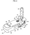
- FIG. 2 is a perspective view of the accessory-grip viewed from the behind thereof;
- FIG. 3 is an exploded perspective view showing a housing of the accessory-grip
- FIG. 4 is a sectional view of the accessory-grip
- FIG. 5 is a plan view of a lock device in which a lock lever is set to a lock position
- FIG. 6 is a plan view of the lock device in which a lock lever is set to a partial release position
- FIG. 7 is a plan view of the lock device in which a lock lever is set to a complete release position
- FIG. 8 is a sectional view showing a connecting condition of the accessory-grip and the camera body
- FIG. 9 is a view showing a state in which a lock release member faces a side surface of a lock button
- FIG. 10 is a view showing a state in which a lock release member separates from the side surface of the lock button
- FIG. 11 is a view showing a rear cover viewed from the inside of the housing
- FIG. 12 a view showing the positional relationship between the lock lever and a guide slot at the lock position
- FIG. 13 is a view showing the positional relationship between the lock lever and the slot at the partial release position
- FIG. 14 is a view showing the positional relationship between the lock lever and the slot at the complete release position
- FIG. 15 is a sectional view showing an interference state of the arm of the lock lever and a lever curtain
- FIG. 16 is a perspective view showing a state in which the lock lever bends the lever curtain.
- FIG. 17 is a view showing the other example of the lever curtain.
- FIG. 1 shows a state in which a camera body 10 and an accessory-grip 20 of an embodiment of the present invention are disassembled, and the camera body 10 is set to a horizontal position.
- the accessory-grip 20 is detachably attached to a bottom surface of the camera body 10 .
- an interchangeable lens 11 is detachably attached to a front surface, and a viewfinder 1 is provided on a center portion of an upper surface.
- a first grip portion 13 On the left side of the camera body 10 viewed from the front thereof, a first grip portion 13 , projecting forward so that the user can easily hold the camera body 10 , is formed, and a first shutter button 14 is provided on the upper surface of the first grip portion 13 .
- triangle rings 15 and 16 are fixed to attach a strap.
- a bulge 21 is formed which projects forward so that the horizontal section shape coincides with the lower end of the first grip portion 13 .
- a second grip portion 22 extending in a horizontal direction projects forward.
- a second shutter button 23 is provided on a portion close to the bulge 21 . Namely, when the camera body 10 is in a vertical position, after being rotated clockwise by about 90 degrees when viewed from the front, the second shutter button 23 faces upward.
- an insert member 24 which houses lead wires for supplying electric power generated by the batteries into electric circuits provided in the camera body 10 .
- the insert member 24 is inserted in a hole (not shown) formed in the camera body 10 .
- Signal contact pins 25 for transmitting electric signals to the electric circuits provided in the camera body 10 are provided on an upper surface of the accessory-grip 20 .
- a positioning pin 26 for positioning the accessory-grip 20 on the camera body 10 when connecting them, and first and second connecting members 27 and 28 , for fixing the accessory-grip 20 to the camera body 10 , are provided.
- FIG. 2 is a perspective view of the accessory-grip 20 when viewed from the behind thereof.
- the housing of the accessory-grip 20 is composed of a front cover 31 (see FIG. 3) and a rear cover 32 , and an opening formed on a side surface of the housing is closed by a lid 37 .
- a guide slot 61 extending in a horizontal direction, is formed on the rear cover 32 , and a lock lever 62 of a lock device is inserted through the guide slot 61 , so as to maintain a connecting condition of the camera body 10 and the accessory-grip 20 .
- the lock lever 62 is movable along the guide slot 61 , and thus movably supported by the housing.
- a lock release member 63 is provided close to the right end of the guide slot 61 .
- the lock release member 63 is movable in a direction vertical to a wall surface of the rear cover 32 .
- a power source switch 64 is provided under the lock release member 63 , and an AE lock button 65 is provided to a right side of the power source switch 64 .
- an electric power supply from the batteries provided in the accessory-grip 20 to the electric circuits provided in the camera body 10 , is started.
- an AE lock button 65 an exposure condition is fixed for a predetermined period of time.
- a remote-control switch 66 for turning ON and OFF a remote-control photographing mode, and a remote-control window 67 for receiving an infrared light beam ejected from a remote-controller (not shown) when performing a remote-control photographing operation, are provided.
- FIGS. 3 and 4 a construction of the housing of the accessory-grip 20 will be described below. Note that, in FIG. 3, the insert member 24 (see FIGS. 2 and 3) is omitted.
- the housing of the accessory-grip 20 has the front cover 31 corresponding to a front surface of the camera body 10 , the rear cover 32 corresponding to a rear surface of the camera body 10 , and a partition 33 provided between the front cover 31 and the rear cover 32 .
- the front cover 31 and the rear cover 32 have approximately the same lengths as the breadth of the camera body 10 , and are fixed to the partition 33 by a screw 34 .
- the front cover 31 has the bulge 21 and the second grip portion 22 , and a first notch 35 is formed on an end portion of the second grip portion 22 opposite to the bulge 21 .
- a second notch 36 is formed in the rear cover 32 at a portion corresponding to the first notch 35 .
- the partition 33 is slightly shorter than the front cover 31 and the rear cover 32 , and extends over approximately the whole breadth of the camera body 10 .
- a lot of ribs 38 recessed in an arc-shape along an outer surface of a battery, are formed on a wall surface of the front cover 31 , the rear cover 32 , and the partition 33 .
- battery chambers 41 for housing a plurality of batteries are defined, and the partition 33 functions as a wall separating the batteries in the battery chambers 41 .
- the partition 33 has a flat plate 39 vertical to the optical axis of the interchangeable lens (photographing optical system) 11 .
- a tripod internal thread member 43 is provided in a hole 42 formed on a lower surface of the partition 33 and around the center of the longitudinal direction of the partition 33 (i.e., the breadth direction of the camera body 10 ).
- the front cover 31 , the rear cover 32 , and the partition 33 are made of resin, and are molded by a die assembly having an upper die and a lower die, which are displaced in a horizontal direction in FIG. 4 .
- the housing of the accessory-grip 20 is divided into the front cover 31 and the rear cover 32 , which are connected by the partition 33 . Due to this, in the manufacturing process of the resin-molded members, the mold-release operation of the resin-molded members from the dies is easy, so that the manufacturing cost is reduced.
- the portions where the screw 34 for connecting the covers 31 and 32 to the partition 33 is provided are recessed, and a bottom rubber cover 46 is provided to these recessed portions 44 .
- An external rubber cover 47 is adhered on an upper surface of the front cover 31 .
- a metal support plate 68 is placed on an upper surface of the partition 33 , and an opening formed on an upper portion of the front cover 31 and the rear cover 32 is closed by an upper plate 48 .
- Rectangular openings 48 a , 48 b , and 48 c are formed in the upper plate 48 .
- disk-shaped pads 48 d formed of elastic material such as rubber are provided on the upper plate 48 and are close to the short sides of the openings 48 a , 48 b , and 48 c.
- FIG. 5 shows a state in which the lock lever 62 is set to a lock position so that the accessory-grip 20 is firmly connected to the camera body 10
- FIG. 6 shows a state in which the lock lever 62 is set to a partial release position so that the accessory-grip 20 is partially connected to the camera body 10
- FIG. 7 shows a state in which the lock lever 62 is set to a complete release position so that the accessory-grip 20 is completely released from the camera body 10 .
- the lock lever 62 is moved among the lock position, the partial release positions, and the complete release position, which are different from each other.
- the lock lever 62 is swingably supported by a pivot pin 68 a fixed to the support plate 68 to move along the support plate 68 .
- An arm 62 a of the lock lever 62 projects outward from an edge of the support plate 68 , and a lock button (i.e., operating portion) 62 b is provided at the tip of the arm 62 a .
- a guide pin 62 c is planted on a surface of the arm 62 a , the surface facing the support plate 68 .
- the guide pin 62 c is engaged with an arc-shaped slot 68 b , which is formed in the support plate 68 b and of which the center of curvature is the pivot pin 68 a .
- the lock lever 62 is rotatable in a range in which the guide pin 62 c can move within the slot 68 b .
- the lock lever 62 has first and second projecting portions 62 e and 62 f extending from the pivot pin 68 a in roughly a vertical direction to the arm 62 a .
- An annular collar 62 g is pivotally provided to a tip portion of the first projecting portion 62 e , and a press pin 62 h is fixed on a tip portion of the second projecting portion 62 f.
- the first connecting member 27 is guided by four guide rollers 68 c provided on an upper surface of the support plate 68 , so that the first connecting member 27 is movably supported by the support plate 68 or the housing.
- a connecting claw 27 a formed on an edge of the first connecting member 27 projects from the opening 48 a (see FIG. 3) of the upper plate 48 , and is displaced in association with the lock lever 62 , so that the connecting claw 27 a can be engaged with an edge of an opening formed in a bottom surface of the camera body 10 , as will be described later.
- the first connecting member 27 has a rectangular opening 27 b (third opening).
- Signal contact pins 22 for electrically connecting an electric circuit provided in the accessory-grip 20 and an electric circuit provided in the camera body 10 , are positioned in the opening 27 b . Namely, the signal contact pins 22 project from the opening 48 b (see FIG. 3) of the upper plate 48 , and can be in contact with electric contacts provided on a bottom surface of the camera body 10 .
- the first connecting member 27 and the support plate 68 are connected by a pair of tension springs 69 , so that the first connecting member 27 is always urged toward the lock lever 62 , i.e., the opposite direction to the connecting claw 27 a .
- a plate spring 27 c bent in a mount shape is provided on an edge of the first connecting member 27 , the edge being located at an opposite portion of the connecting member 27 to the connecting claw 27 a .
- the collar 62 g of the lock lever 62 can be engaged with the plate spring 27 c . Namely, the first connecting member 27 is pressed by the lock lever 62 through the plate spring 27 c , to displace outward, i.e., toward the connecting claw 27 a.
- An intermediate lever 71 is rotatably supported by the pivot pin 68 d fixed on the support plate 68 .
- An edge 71 a of the intermediate lever 71 on the side of the lock lever 62 , is formed in an arc-shape so as to avoid interfering with the press pin 62 h .
- the notch 71 b with which the press pin 62 h is engaged, is formed on an end portion of the edge 71 a close to the pivot pin 68 d .
- a pin 71 d fixed on the intermediate lever 71 and a pin 68 e fixed on the support plate 68 are connected by an omega spring 73 . Due to this, the intermediate lever 71 is stably rested at a first position (see FIG.
- the second connecting member 28 is guided by four guide rollers 68 f provided on an upper surface of the support plate 68 , and is movably supported by the support plate 68 , i.e., the housing.
- the moving direction of the second connecting member 28 is parallel to the moving direction of the first connecting member 27 , and these are opposite to each other.
- one of the guide rollers 68 f is the pin 68 e described above.
- a connecting claw 28 a is formed on the second connecting member 28 .
- the connecting claw 28 a projects through the opening 48 c (see FIG. 3) of the upper plate 48 .
- the second connecting member 28 is displaced in association with the lock lever 62 , so that the connecting claw 28 a can be engaged with an edge of an opening formed in a bottom surface of the camera body 10 .
- First and second guide slits 28 b and 28 c extending along the moving direction, are formed on the second connecting member 28 .
- the first guide slit 28 b is engaged with the pivot pin 68 a
- the second guide slit 28 c is engaged with the pivot pin 68 d .
- a connecting pin 28 d fixed on the connecting member 28 is engaged with the hole 71 e of the intermediate lever 71 .
- FIG. 8 is a sectional view showing a connecting condition in which the accessory-grip 20 is connected to the camera body 10 .
- the connecting claw 27 a of the first connecting member 27 has a flat plate inclining by approximately 45 degrees relative to the moving direction, and the moving range of the connecting claw 27 a is approximately half the breadth of the opening 10 a of the camera body 10 .
- the connecting claw 28 a of the second connecting member 28 has a rising portion 28 e extending vertically to the moving direction and an engaging portion 28 f extending from an upper end of the rising portion 28 e and slightly inclining by an angle close to the horizontal.
- the moving range of the connecting claw 28 a is around the same as the breadth of an opening 10 b of the camera body 10 , and the breadth of the engaging portion 28 f is less than the breadth of the opening 10 b .
- the pads 48 d are sandwiched between the accessory-grip 20 and the camera body 10 to deform and tightly contact the bottom surface of the camera body 10 .
- This tight contact is due to pressure generated by the inclined planes of the connecting claws 27 a and 28 a , so that ricketiness and slip between the accessory-grip 20 and the camera body 10 is prevented.
- the lock button 62 b is positioned in such a manner that a side surface 62 i of the lock button 62 b is close to the lock release member 63 , and the collar 68 g urges a portion close to a bent portion 27 d of the plate spring 27 c . Accordingly, the first connecting member 27 is depressed by a spring force generated by the collar 62 g urging the plate spring 27 c , so that the first connecting member 27 is displaced toward the connecting claw 27 a , against the spring forces of the tension springs 69 .
- the intermediate lever 71 is rested by the spring force of the omega spring 73 at a position where the intermediate lever 71 presses the second connecting member 28 to the connecting claw 28 a , i.e., outward.
- the first and second connecting members 27 and 28 are positioned separate from each other and are fixed there, and in a state in which the accessory-grip 20 is attached to the camera body 10 , the connecting claws 27 a and 28 a are engaged with the outer edges of the openings 10 a and 10 b of the bottom surface of the camera body 10 , so that the accessory-grip 20 and the camera body 10 are firmly connected to each other.
- the lock release member 63 When the accessory-grip 20 is to be released from the camera body 10 , first, the lock release member 63 is depressed to the first connecting member 27 , so that the side surface 62 i of the lock button 62 b is exposed. Thus, the lock lever 62 becomes easily operable, and if the side surface 62 i is depressed toward the second connecting member 28 , the collar 62 g gets over the bent portion 27 d by bending the plate spring 27 c , and the lock lever 62 is then stopped at a position where the press pin 62 h is engaged with the notch 71 b of the intermediate lever 71 . This condition is the partial release position shown in FIG.
- the lock lever 62 is further moved from the partial release position (see FIG. 6) to the side of the second connecting member 28 , the press pin 62 h depresses the notch 71 b , so that the intermediate lever 71 is rotated counterclockwise in FIG. 7 .
- the second connecting member 28 is moved inward (i.e., the side of the lock lever 62 ) through the connecting pin 28 d , and is stopped at the complete release position shown in FIG. 7 .
- the connecting claw 28 a of the second connecting member 28 is released from the edge of the opening 10 b of the camera body 10 .
- the connecting claws 27 a and 28 a of the first and second connecting members 27 and 28 are both released from the camera body 10 , so that the accessory-grip 20 is released from the camera body 10 .
- the accessory-grip 20 When the accessory-grip 20 is to be attached to the camera body 10 , first, the accessory-grip 20 is brought into contact with a bottom surface of the camera body 10 , so that the connecting claws 27 a and 28 a are inserted into the openings 10 a and 10 b of the camera body 10 . Then, the lock lever 62 , set to the complete release position (see FIG. 7 ), is rotated to the side of the first connecting member 27 , and is set to the lock position (see FIG. 5 ). Thus, the connecting members 27 and 28 are displaced outward, so that the connecting claws 27 a and 28 a are engaged with the edges of the openings 10 a and 10 b of the camera body 10 .
- the lock lever 62 is rotated from the lock position (FIG. 5) to the partial release position (FIG. 6 ), and is temporarily fixed at the partial release position, where the accessory-grip 20 is still connected to the camera body 10 through the second connecting member 28 . Therefore, the accessory-grip 20 is prevented from dropping accidentally. Further, an operation, in which the lock lever 62 is moved from the lock position to the complete release position via the partial release position, and an operation, in which the lock lever 62 is moved from the complete release position to the lock position, are performed only by rotating the lock lever 62 . Thus, the attaching operation and the detaching operation between the accessory-grip 20 and the camera body 10 are extremely simple.
- the plate spring 27 c is provided to the first connecting member 27 , when the lock lever 62 is to be rotated, the lock lever 62 should be pressed with a force which is large enough for the collar 62 g to get over the bent portion 27 d of the plate spring 27 c .
- the click-stop mechanism is provided to give a predetermined resistance against the movement of the lock lever 62 when the lock lever 62 is switched between the lock position and the partial release position, the lock lever 62 set to the lock position is prevented from being accidentally operated.
- FIGS. 9 and 10 show structures of the lock lever 62 and the lock release member 63 .
- the lock release member 63 is disposed at a position, which is close to an end portion of the lock lever 62 fixed at the lock position, and which is opposite to the partial release position relative to the lock lever 62 .
- a pair of slits 63 a is formed in the lock release member 63 , with which a pair of pins 68 g provided to the support plate 68 are engaged.
- the slits 63 a extend in a direction substantially perpendicular to the moving direction of the lock lever 62 .
- the lock release member 63 is movable in a direction substantially perpendicular to the moving direction of the lock lever 62 .
- a hook 63 b formed on a lower end portion of the lock release member 63 and a pin 68 h provided to the support plate 68 are connected by a spring 63 c , so that the lock release member 63 is always urged toward the rear cover 32 (see FIG. 3 ), i.e., in a direction in which the lock release member 63 projects from the rear cover 32 (i.e., the upper direction in FIGS. 9 and 10 ).
- a lock release button 63 d is provided to an end portion of the lock release member 63 .
- An end surface 63 e of the lock release button 63 d is not perpendicular to the moving direction of the lock release member 63 , but is slightly inclined to a plane vertical to the moving direction. Due to this, the lock release member 63 becomes easily depressed.
- An engaging notch 63 f is formed in the lock release member 63 .
- the guide pin 62 c of the lock lever 62 is engaged with the engaging notch 63 f , so that the lock lever 62 is fixed at the lock position.
- the lock release member 63 is depressed against the spring force of the spring 63 c as shown in FIG. 10
- the guide pin 62 c is released from the engaging notch 63 f , so that the lock lever 62 become rotatable.
- the side surface 62 i of the lock button 62 d is exposed by the displacement of the lock release button 63 d , the user can easily operate the lock button 62 b .
- the lock button 62 b cannot be accidentally pressed.
- FIG. 11 is a view showing the rear cover 32 viewed from the inside of the housing.
- the guide slot 61 formed in the rear cover 32 , is extended in a horizontal direction.
- the guide slot 61 is defined by an upper wall 61 a and a lower wall 61 b .
- a lever curtain 81 is adhered on an upper edge of the lower wall 61 b .
- the lever curtain 81 is a rectangular piece of cloth, which has the substantially same length as that of the guide slot 61 .
- One surface of the lever curtain 81 is coated by a rubber layer.
- the upper long side 81 a of the lever curtain 81 is positioned close to the edge of the upper wall 61 a , so that the lever curtain 81 covers the guide slot 61 .
- slits 81 b and 81 c are formed close to the both end portions.
- the positions, where the slits 81 b and 81 c are formed, are the both ends of a range within which the lock lever 62 is moved in the guide slot 61 .
- Each of the slits 81 b and 81 c is extended along the breadth direction of the lever curtain 81 , and reaches the upper long side 81 a of the lever curtain 81 .
- the tip of the lock lever 62 or the lock button 62 b is projected outside the housing through the guide slot 61 .
- the lock lever 62 is rotatable around the pivot pin 68 a , and with the rotation, the arm 62 a of the lock lever 62 is moved along the longitudinal direction of the guide slot 61 .
- An upper end portion 81 d (see FIG. 15) of the lever curtain 81 is bent to the outside of the rear cover 32 by the arm 62 a .
- a portion of the lever curtain 81 which does not interfere with the arm 62 a , maintains the upright condition due to the restitution force of the lever curtain 81 .
- the lever curtain 81 covers the guide slot 61 while allowing the lock lever 62 to move along the guide slot 61 , and thus foreign matter such as dust is prevented from entering the accessory-grip 20 through the guide slot 61 .
- FIG. 17 shows another example of the lever curtain 81 , in which an end portion of the slit 81 b close to the long side 81 a is chamfered to form a triangle notch 81 g . Due to this construction, in a state shown in FIG. 16, the curvature of the center portion 81 f of the lever curtain 81 becomes greater, so that the guide slot 61 can be better covered.
- the lever curtain 81 is advantageous in comparison with one in which a slit is formed along the longitudinal direction of the curtain, and the arm 62 a is inserted in the slit to move along the slit.
Abstract
Description
Claims (19)
Applications Claiming Priority (4)
| Application Number | Priority Date | Filing Date | Title |
|---|---|---|---|
| JPP2001-082122 | 2001-03-22 | ||
| JP2001082122A JP4087076B2 (en) | 2001-03-22 | 2001-03-22 | Accessories for camera holding |
| JP2001082110A JP3958530B2 (en) | 2001-03-22 | 2001-03-22 | Locking device for camera holding accessories |
| JPP2001-082110 | 2001-03-22 |
Publications (2)
| Publication Number | Publication Date |
|---|---|
| US20020136553A1 US20020136553A1 (en) | 2002-09-26 |
| US6826366B2 true US6826366B2 (en) | 2004-11-30 |
Family
ID=26611766
Family Applications (1)
| Application Number | Title | Priority Date | Filing Date |
|---|---|---|---|
| US10/101,962 Expired - Fee Related US6826366B2 (en) | 2001-03-22 | 2002-03-21 | Lock device for accessory-grip |
Country Status (1)
| Country | Link |
|---|---|
| US (1) | US6826366B2 (en) |
Cited By (6)
| Publication number | Priority date | Publication date | Assignee | Title |
|---|---|---|---|---|
| US20070058075A1 (en) * | 2005-09-09 | 2007-03-15 | Anton/Bauer, Inc. | Camera system and power supply for optical recording devices |
| US20070076115A1 (en) * | 2005-09-12 | 2007-04-05 | Junji Hirooka | Image pickup apparatus |
| US20090002524A1 (en) * | 2005-09-09 | 2009-01-01 | Anton/Bauer, Inc. | Camera system and power supply for optical recording devices |
| US20130002945A1 (en) * | 2011-07-01 | 2013-01-03 | Panasonic Corporation | Case structure and imaging device |
| US8804030B2 (en) | 2010-04-08 | 2014-08-12 | Anton/Bauer, Inc. | Camera system and power supply for optical recording devices |
| US11073748B2 (en) * | 2018-09-04 | 2021-07-27 | Canon Kabushiki Kaisha | Accessory and camera system |
Families Citing this family (2)
| Publication number | Priority date | Publication date | Assignee | Title |
|---|---|---|---|---|
| JP2020003613A (en) * | 2018-06-27 | 2020-01-09 | キヤノン株式会社 | Electronic apparatus |
| US11622074B2 (en) * | 2019-12-24 | 2023-04-04 | Canon Kabushiki Kaisha | Electronic apparatus and accessory system |
Citations (3)
| Publication number | Priority date | Publication date | Assignee | Title |
|---|---|---|---|---|
| US4110770A (en) * | 1976-08-06 | 1978-08-29 | Balda-Werke Photographische Gerate Und Kunststoff Gmbh & Co. Kg | System for mounting accessories on a camera |
| US5568217A (en) | 1994-12-28 | 1996-10-22 | Asahi Kogaku Kogyo Kabushiki Kaisha | Back cover lock mechanism of a camera |
| US6246840B1 (en) | 1998-11-24 | 2001-06-12 | Asahi Kogaku Kogyo Kabushiki Kaisha | Locking mechanism for backside cover of camera |
-
2002
- 2002-03-21 US US10/101,962 patent/US6826366B2/en not_active Expired - Fee Related
Patent Citations (3)
| Publication number | Priority date | Publication date | Assignee | Title |
|---|---|---|---|---|
| US4110770A (en) * | 1976-08-06 | 1978-08-29 | Balda-Werke Photographische Gerate Und Kunststoff Gmbh & Co. Kg | System for mounting accessories on a camera |
| US5568217A (en) | 1994-12-28 | 1996-10-22 | Asahi Kogaku Kogyo Kabushiki Kaisha | Back cover lock mechanism of a camera |
| US6246840B1 (en) | 1998-11-24 | 2001-06-12 | Asahi Kogaku Kogyo Kabushiki Kaisha | Locking mechanism for backside cover of camera |
Cited By (10)
| Publication number | Priority date | Publication date | Assignee | Title |
|---|---|---|---|---|
| US20070058075A1 (en) * | 2005-09-09 | 2007-03-15 | Anton/Bauer, Inc. | Camera system and power supply for optical recording devices |
| US20090002524A1 (en) * | 2005-09-09 | 2009-01-01 | Anton/Bauer, Inc. | Camera system and power supply for optical recording devices |
| US7724303B2 (en) * | 2005-09-09 | 2010-05-25 | Anton/Bauer, Inc. | Camera system and power supply for optical recording devices |
| US7864244B2 (en) | 2005-09-09 | 2011-01-04 | Anton/Bauer, Inc. | Camera system and power supply for optical recording devices |
| US20070076115A1 (en) * | 2005-09-12 | 2007-04-05 | Junji Hirooka | Image pickup apparatus |
| US7825983B2 (en) * | 2005-09-12 | 2010-11-02 | Canon Kabushiki Kaisha | Image pickup apparatus having a frame |
| US8804030B2 (en) | 2010-04-08 | 2014-08-12 | Anton/Bauer, Inc. | Camera system and power supply for optical recording devices |
| US20130002945A1 (en) * | 2011-07-01 | 2013-01-03 | Panasonic Corporation | Case structure and imaging device |
| US8801303B2 (en) * | 2011-07-01 | 2014-08-12 | Panasonic Corporation | Case structure and imaging device |
| US11073748B2 (en) * | 2018-09-04 | 2021-07-27 | Canon Kabushiki Kaisha | Accessory and camera system |
Also Published As
| Publication number | Publication date |
|---|---|
| US20020136553A1 (en) | 2002-09-26 |
Similar Documents
| Publication | Publication Date | Title |
|---|---|---|
| US9465279B2 (en) | Image pickup apparatus with movable locking member | |
| JP5106060B2 (en) | Imaging device | |
| US7623773B2 (en) | Accessory device for image-pickup apparatus | |
| US6826366B2 (en) | Lock device for accessory-grip | |
| US11073748B2 (en) | Accessory and camera system | |
| US7058295B2 (en) | Electronic equipment | |
| KR20100076791A (en) | Coupling apparatus for accessories of camera | |
| US6979138B2 (en) | Mount lock apparatus for camera | |
| JP4087076B2 (en) | Accessories for camera holding | |
| JP3958530B2 (en) | Locking device for camera holding accessories | |
| JP2007212928A (en) | Accessory equipment, and attaching structure of electronic equipment and accessory equipment | |
| JP2915982B2 (en) | camera | |
| US6487373B2 (en) | Shutter release unit having multiple functions | |
| US7149418B2 (en) | Camera guard with bezel and ring | |
| JPH11274758A (en) | Retaining device for small-size electronic equipment | |
| JPH03231731A (en) | Wireless remote control device for camera | |
| JPS6331048Y2 (en) | ||
| JPH08278546A (en) | Structure for holding armature | |
| JP2016045477A (en) | camera | |
| JP3019082U (en) | Operation button structure | |
| US7120355B2 (en) | Camera assembly having lens turret and independently movable rocker | |
| JP5266927B2 (en) | Lens barrel, mount structure of optical device to which lens barrel can be mounted, and camera | |
| JP2021149054A (en) | Camera device | |
| JP6271995B2 (en) | Imaging device | |
| US7123828B2 (en) | Camera assemblies having overlapping rocker and link projections |
Legal Events
| Date | Code | Title | Description |
|---|---|---|---|
| AS | Assignment |
Owner name: ASAHI KOGAKU KOGYO KABUSHIKI KAISHA, JAPAN Free format text: ASSIGNMENT OF ASSIGNORS INTEREST;ASSIGNORS:KANEKO, HIDEFUMI;MACHIDA, KATSUKI;REEL/FRAME:012718/0683;SIGNING DATES FROM 20020314 TO 20020318 |
|
| AS | Assignment |
Owner name: PENTAX CORPORATION, JAPAN Free format text: CHANGE OF NAME;ASSIGNOR:ASAHI KOGAKU KOGYO KABUSHIKI KAISHA;REEL/FRAME:015926/0364 Effective date: 20021001 |
|
| FEPP | Fee payment procedure |
Free format text: PAYOR NUMBER ASSIGNED (ORIGINAL EVENT CODE: ASPN); ENTITY STATUS OF PATENT OWNER: LARGE ENTITY |
|
| FPAY | Fee payment |
Year of fee payment: 4 |
|
| AS | Assignment |
Owner name: HOYA CORPORATION, JAPAN Free format text: MERGER;ASSIGNOR:PENTAX CORPORATION;REEL/FRAME:026970/0554 Effective date: 20080331 |
|
| AS | Assignment |
Owner name: PENTAX RICOH IMAGING COMPANY, LTD., JAPAN Free format text: CORPORATE SPLIT;ASSIGNOR:HOYA CORPORATION;REEL/FRAME:027315/0115 Effective date: 20111003 |
|
| FPAY | Fee payment |
Year of fee payment: 8 |
|
| REMI | Maintenance fee reminder mailed | ||
| LAPS | Lapse for failure to pay maintenance fees | ||
| STCH | Information on status: patent discontinuation |
Free format text: PATENT EXPIRED DUE TO NONPAYMENT OF MAINTENANCE FEES UNDER 37 CFR 1.362 |
|
| FP | Lapsed due to failure to pay maintenance fee |
Effective date: 20161130 |