US6830347B2 - Eye viewing device comprising eye cup - Google Patents
Eye viewing device comprising eye cup Download PDFInfo
- Publication number
- US6830347B2 US6830347B2 US09/783,224 US78322401A US6830347B2 US 6830347 B2 US6830347 B2 US 6830347B2 US 78322401 A US78322401 A US 78322401A US 6830347 B2 US6830347 B2 US 6830347B2
- Authority
- US
- United States
- Prior art keywords
- patient
- eye
- orbit
- patient end
- cup
- Prior art date
- Legal status (The legal status is an assumption and is not a legal conclusion. Google has not performed a legal analysis and makes no representation as to the accuracy of the status listed.)
- Expired - Lifetime, expires
Links
Images


Classifications
-
- A—HUMAN NECESSITIES
- A61—MEDICAL OR VETERINARY SCIENCE; HYGIENE
- A61B—DIAGNOSIS; SURGERY; IDENTIFICATION
- A61B3/00—Apparatus for testing the eyes; Instruments for examining the eyes
- A61B3/10—Objective types, i.e. instruments for examining the eyes independent of the patients' perceptions or reactions
- A61B3/12—Objective types, i.e. instruments for examining the eyes independent of the patients' perceptions or reactions for looking at the eye fundus, e.g. ophthalmoscopes
- A61B3/125—Objective types, i.e. instruments for examining the eyes independent of the patients' perceptions or reactions for looking at the eye fundus, e.g. ophthalmoscopes with contact lenses
-
- A—HUMAN NECESSITIES
- A61—MEDICAL OR VETERINARY SCIENCE; HYGIENE
- A61B—DIAGNOSIS; SURGERY; IDENTIFICATION
- A61B3/00—Apparatus for testing the eyes; Instruments for examining the eyes
- A61B3/10—Objective types, i.e. instruments for examining the eyes independent of the patients' perceptions or reactions
- A61B3/12—Objective types, i.e. instruments for examining the eyes independent of the patients' perceptions or reactions for looking at the eye fundus, e.g. ophthalmoscopes
Definitions
- the invention relates to eye viewing devices in general and specifically to a hand-held eye viewing device that is adapted to be readily moved into an operative position relative to a patient's eye.
- Retinal viewing ophthalmoscopes in particular should be positioned at a certain radial displacement, angular orientation and axial standoff position relative to a patient's eye for proper operation.
- the task of moving a retinal viewing ophthalmoscope into an operative position relative to an eye is particularly challenging given that in order to provide viewing of different areas of a retina, such devices should be moved between various angular orientations relative to an eye while maintaining certain radial displacement and axial standoff positions.
- the positioning of commercially available hand-held eye viewing devices is customarily controlled entirely by the hand-eye coordination of a physician.
- a physician manually moves the device into an operative position depending upon the image of the retina generated by the device's viewing system at the physician's retina.
- an eye viewing device which is adapted to be readily positioned in a desired radial displacement, angular orientation and axial standoff position relative to a patient, and which is adapted to be readily maintained in that desired radial displacement, angular orientation and axial standoff position once that position is attained.
- the invention is an eye viewing device adapted to be readily positioned in an operative position relative to an eye.
- An eye viewing device includes an eye cup having patient end adapted to be received at an eye orbit of a patient, the eye orbit being generally defined by an eyebrow and upper cheekbone of a patient.
- the outer diameter of the patient end of the eye cup is sized to correspond to a patient's eye orbit. Because a center of a patient eye is located substantially at the center of an eye orbit, the sizing of the patient end outer diameter corresponding to an eye orbit operates to aid in the radial displacement positioning of the device.
- the eye cup is made deformable so that contact of the eye cup with a patient alerts a physician that the device is approaching an operative axial standoff position. Making the eye cup deformable also enhances patient comfort.
- the eye cup is made so that the eye viewing device can pivot about a pivot point near the patient end of the eye cup to allow adjustment of the eye viewing device's angular orientation position relative to an eye to visualize various areas of the retina.
- Forming the eye cup so that the eye viewing device pivots about a pivot point toward the eye cup's patient end allows adjustment of an eye viewing devices's angular orientation without substantial disruption of the positioning of the device's illumination and viewing axes relative to a pupil center (i.e., without disruption of the radial position) and therefore without movement of the device from an operative position.
- the eye cup prevents ambient light rays from reaching a patient's eye, thereby substantially eliminating sources of external glare. Furthermore, because the eye cup allows the eye viewing device to be stabilized against an eye orbit during eye viewing, the eye cup eases the task of maintaining an operative viewing position after such an operative position is achieved.
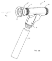
- FIG. 1A is a perspective view of an eye cup-equipped eye viewing device as seen in use
- FIG. 1B is another perspective view of an eye viewing device according to the invention.
- FIG. 2A is a perspective view of an eye cup according to the invention.
- FIG. 2B is a top view of an eye cup according to the invention.
- FIG. 2C is a bottom view of an eye cup according to the invention.
- FIG. 2D is a side view of an eye cup according to the invention.
- FIG. 2E is a cross-sectional side view of an eye cup according to the invention.
- FIG. 2F is a side view of an eye cup according to the invention in a deformed, or compressed configuration.
- FIG. 2G is a side view of an eye cup with a change of angular orientation according to the invention.
- FIG. 3A is a diagram illustrating a conical illumination eye viewing device at a first axial standoff position relative to an eye as exists during the entry process
- FIG. 3B in a diagram illustrating a conical illumination eye viewing device at a second axial standoff position relative to an eye, typical of an operative position
- FIG. 4A is a perspective view of a device housing patient end
- FIG. 4B is a cross-sectional side view of a magnifier lens assembly engaged in a device housing
- FIG. 4C is a perspective view of a magnifier assembly attachment or filter assembly attachment according to the invention.
- FIG. 4D is a perspective view of an otoscope attachment according to the invention.
- FIG. 4E is a perspective view of an episcope attachment according to the invention.
- Retinal viewing ophthalmoscopes In particular, must be positioned at specific radial displacement and axial standoff positions relative to a patient's eye in order to achieve operative illumination and imaging of a retina. Retinal viewing ophthalmoscopes also must be positioned at a specific angular orientation relative to an eye to allow viewing of a particular area of a retina not observable in the central view.
- radial displacement herein refers to the radial distance between a patient's pupil center and an imaging axis, a i , of device 10 .
- angular orientation herein refers to the angle formed between the imaging axis of device 10 and the axis of a patient's pupil
- axial standoff herein refers to the spacing between device 10 and a patient's eye along the imaging axis, a i .
- FIG. 1A An eye viewing device adapted to be readily positioned in a desired radial displacement, angular orientation and axial standoff position relative to a patient's eye is described with reference to FIGS. 1A-3C.
- device 10 includes a housing 12 which comprises patient end 14 , a physician or observer end 16 , and a handle 18 .
- patient end 14 has disposed thereon an eye cup 20 which as will be explained herein is useful in achieving proper radial displacement, angular orientation, and axial offset positioning of device 10 relative to a patient's eye.
- a physician moves device 10 toward a patient's eye orbit 25 until bottom surface 26 (FIG. 1B) of patient end 22 of eye cup 20 is substantially in contact with an eye orbit 25 of a patient.
- device 10 is a retinal viewing ophthalmoscope
- a physician during the course of moving device 10 into an operative position, further attempts to position the device such that a “spot” retinal image (known as the “red reflex” image) is continuously generated by the device's viewing system.
- the outer diameter OD of eye cup patient end 22 should be sized to substantially correspond to an eye orbit 25 of a patient (FIG. 1 A). Because a patient's pupil 32 (FIG. 3A) is located substantially at a center of an eye orbit, contact with an eye orbit 25 of an eye cup having an outer diameter substantially corresponding to orbit 25 radially places device 10 such that the axis, a c , (FIG. 2F) of eye cup 20 at patient end 22 passes substantially through a center of a patient's pupil.
- eye cup 20 is normally disposed on housing 12 such that eye cup axis, a c , substantially coincides with the imaging axis, a i , of device 10 , contact of eye cup 20 with an eye orbit operates to align the device's imaging axis with a patient's pupil (i.e. with minimal radial displacement).
- eye cup 20 is configured to have an exposed length L, as seen in FIG. 2D, such that contact of cup 20 with an eye orbit alerts a physician that device 10 is approaching or is at a proper axial standoff position from a patient's eye.
- eye cup 20 can be substantially rigid such that the proper axial standoff position of a device relative to an eye is achieved when eye cup 20 first comes in contact with orbit 25 .
- eye cup 20 is made deformable.
- contact of eye cup 20 with an eye orbit 25 alerts a physician that the device is approaching a proper axial standoff position.
- An operative axial standoff position of device having a deformable eye cup is achieved when eye cup 20 is in a deformed configuration, as is shown in FIGS. 2F and 2G.
- Eye cup 20 deformable adapts the eye cup for variations in eye configurations between eyes of different patients and increases patient comfort.
- Eye cup 20 can be made deformable by configuring eye cup 20 in a bellows configuration as is indicated in FIGS. 1A-2G and which will be described in greater detail hereinbelow.
- FIGS. 3A and 3B Axial standoff positioning between an eye viewing device 10 and an eye must be substantially precise in retinal viewing devices having conical illumination as can be seen by comparison of FIGS. 3A and 3B.
- Conical illumination systems generate a cone of light having light rays that converge at an apex and diverge thereafter.
- FIG. 3A shows a cone of light illumination in which apex, ax, of the cone of light 34 is spacely apart from a pupil 32 while
- FIG. 3B shows a cone of light illumination in which apex, ax, of cone of light 34 is positioned at a pupil 32 . Comparing to FIGS.
- illumination of a retina illuminated by a conical illumination system improves when apex, ax, of the conical illumination is substantially positioned at a pupil.
- apex, ax, of cone of light 34 is at a position forward of pupil 32 , indicated in FIG. 3A when eye cup 20 first contacts an eye orbit 25 , and at a position substantially within pupil 32 when eye cup 20 is in an operative deformed configuration.
- Examples of retinal viewing ophthalmoscopes having conical illumination systems are described in commonly assigned U.S. Pat. No. 6,065,837, and concurrently filed Application Ser. No. 09/444,161 entitled “Eye Viewing Device for Retinal Viewing through Undilated Pupil,” both of which are incorporated herein by reference.
- eye cup 20 preferably is adapted to allow device 10 to be readily positioned at varying angular orientations relative to an eye. It is common to adjust the field of view of many types of eye viewing devices by adjusting the device's angular orientation relative to an eye 27 (FIG. 3 A). For example, different regions of a retina 33 can be viewed through a pupil with a retinal viewing ophthalmoscope by adjusting the angular orientation of the ophthalmoscope while maintaining the imaging axis of the device in a position substantially centered in a pupil 32 .
- Eye cup 20 can be made to allow adjustment of device angular orientation relative to an eye by configuring eye cup 20 such that device 10 can be pivoted about a point, P, on eye cup axis, a c .
- eye cup 20 can be made so that device 10 is moveable between a first configuration indicated in FIG. 2F in which the axis, a c , of eye cup 20 substantially coincides with the imaging axis, a i , of device throughout the length of eye cup 20 and a second configuration indicated in FIG. 2G in which eye cup axis, a c , is pivoted about a pivot point P.
- the imaging system of a retinal viewing ophthalmoscope generates a retinal image when the device's imaging axis, a i , passes through a patient's pupil 32 .
- Eye cup 20 is disposed on housing 12 so that eye cup axis, a c , toward eye cup upper end 23 substantially coincides with the device's imaging axis, a i . Accordingly, it can be seen that configuring eye cup 20 so that device 10 pivots about a pivot point, P, proximate a pupil 32 , allows retinal imaging to be maintained throughout the moving of the ophthalmoscope from an angular orientation position normal to a pupil 32 to a position oblique relative the pupil.
- the bellows-configured eye cup described with reference to FIGS. 2A-2G can be made to pivot at a pivot point proximate a pupil 32 by configuring eye cup 20 to have proportionately thinner material at the bellows sections toward patient end 22 of eye cup 20 .
- the walls of eye cup 20 are formed gradually thinner toward patient end 22 to produce pivoting toward patient end 22 .
- First bellows section 41 has a smaller thickness than second bellows section 42 which has a smaller thickness than third bellows section 43 .
- the walls 47 of the third bellows 43 are substantially thicker than the walls 45 and 46 of the first and second bellows 41 , and 42 , respectively.
- the configuration shown in FIG. 2E provides an eye cup which pivots substantially toward patient end 22 when eye cup 20 is in an axially deformed or compressed configuration and the device is moved angularly.
- eye cup 20 should be made substantially opaque so that eye cup 20 substantially blocks ambient light rays from reaching a patient's eye. By blocking ambient light rays, eye cup 20 operates to substantially eliminate this source of external glare.
- eye cup 20 allows device 10 to be stabilized against a patient's eye orbit during eye viewing. Accordingly, in addition to aiding the task of positioning device 10 in an operative position, eye cup 20 eases the task of maintaining an operative position once an operative position has been achieved.
- Bottom surface 26 of cup 20 which is the patient contact surface, preferably defines a flange configuration as is best seen by bottom view FIG. 2 C.
- the flange-shaped bottom surface enhances patient comfort and, by providing for substantial contact of cup 20 with eye orbit 25 , encourages radial stabilization of eye cup 20 on eye orbit 25 .
- bottom surface 26 is substantially circular, it is contemplated that the bottom surface 26 can be configured in other configurations, including configurations that more precisely approximate the actual shape of a patient's eye orbit.
- eye cup outer diameter OD is sized to correspond to an eye orbit as explained previously, inner diameter ID of cup 20 is sized so as not to substantially interfere with a patient's eyelashes during blinking or to interfere with the illumination and imaging performance of the eye viewing device.
- Eye cup 20 can have an outer diameter of between about 35 mm and 55 mm and an inner diameter of between about 20 mm and about 40 mm. In the embodiment of FIGS. 2A-2G eye cup 20 has an outer diameter of about 45 mm and an inner diameter of about 32 mm at bottom surface 26 .
- Eye cup 20 may be made from moldable elastomeric or plastic material that is biocompatible, cleanable, sterilizable, and of low durometer.
- a preferred material for eye cup 20 is silicone.
- eye cup 20 includes a top connector section 48 as best seen in FIG. 2A, which adapts eye cup 20 to be detachably attached to an eye viewing device housing 12 .
- eye cup 20 is made to be detachably held in place in housing 12 ribs that deform during engagement with or disengagement from, the housing.
- top connector section 48 includes ribs 53 adapted to be received in complementarily formed lip 54 of housing 12 , as seen in FIG. 4 A. Lip 54 may be part of a nose interface 55 forming patient end 14 of housing 12 .
- Nose interface 55 may comprise a relatively stiff elastomeric material.
- attachments received in lip 54 can be formed from either a flexible material or from a substantially rigid material such as metal or plastic.
- eye cup 20 should be formed so that upper end 23 (FIG. 2E) of eye cup 20 is held substantially stable in housing 12 toward upper end 23 but pivots readily about a pivot point, P (FIG. 2 G), along axis, a c , toward patient end 22 .
- FIG. 4C is a magnifier lens assembly 60 which may be detachably attached to housing 12 in the manner of eye cup 20 .
- a magnifier lens assembly 60 which may be detachably attached to housing 12 in the manner of eye cup 20 .
- attaching magnifier lens assembly 60 to housing 12 allows device 10 to be used as a cornea viewing device.
- Other attachments which may be detachably attached to housing 12 in substantially the manner of eye cup 20 or magnifier lens assembly 60 includes optical filter attachments, otoscope attachments, and episcope attachments.
- a filter assembly attachment for attachment to housing 12 may comprise the general configuration of assembly 60 as show in FIG. 4 C.
- An exemplary otoscope assembly attachment 62 is shown in FIG. 4D while an exemplary episcope assembly attachment 64 is shown in FIG. 4 E.
- the above assembly attachments 60 , 62 , 64 have ribs 53 , allowing attachments to be detachably received by housing 12 in substantially the manner of eye cup 20 .
Abstract
Description
Claims (12)
Priority Applications (3)
| Application Number | Priority Date | Filing Date | Title |
|---|---|---|---|
| US09/783,224 US6830347B2 (en) | 2001-02-14 | 2001-02-14 | Eye viewing device comprising eye cup |
| AU2002321991A AU2002321991A1 (en) | 2001-02-14 | 2002-02-11 | Eye viewing device comprising eye cup |
| PCT/US2002/003956 WO2002096279A2 (en) | 2001-02-14 | 2002-02-11 | Eye viewing device comprising eye cup |
Applications Claiming Priority (1)
| Application Number | Priority Date | Filing Date | Title |
|---|---|---|---|
| US09/783,224 US6830347B2 (en) | 2001-02-14 | 2001-02-14 | Eye viewing device comprising eye cup |
Publications (2)
| Publication Number | Publication Date |
|---|---|
| US20030063386A1 US20030063386A1 (en) | 2003-04-03 |
| US6830347B2 true US6830347B2 (en) | 2004-12-14 |
Family
ID=25128557
Family Applications (1)
| Application Number | Title | Priority Date | Filing Date |
|---|---|---|---|
| US09/783,224 Expired - Lifetime US6830347B2 (en) | 2001-02-14 | 2001-02-14 | Eye viewing device comprising eye cup |
Country Status (3)
| Country | Link |
|---|---|
| US (1) | US6830347B2 (en) |
| AU (1) | AU2002321991A1 (en) |
| WO (1) | WO2002096279A2 (en) |
Cited By (8)
| Publication number | Priority date | Publication date | Assignee | Title |
|---|---|---|---|---|
| US20070206153A1 (en) * | 2002-08-21 | 2007-09-06 | Neuroptics, Inc. A California Corporation | Intelligent patient interface for ophthalmic instruments |
| US20080012898A1 (en) * | 2006-07-11 | 2008-01-17 | Canon Kabushiki Kaisha | Ink jet recording head |
| US7784940B2 (en) | 1998-11-24 | 2010-08-31 | Welch Allyn, Inc. | Eye viewing device comprising video capture optics |
| US20140192322A1 (en) * | 2013-01-08 | 2014-07-10 | Altek Corporation | Imaging apparatus |
| US8786210B2 (en) | 2010-06-30 | 2014-07-22 | Welch Allyn, Inc. | Drive circuit for light emitting diode |
| US20150223678A1 (en) * | 2014-02-12 | 2015-08-13 | Welch Allyn, Inc. | Eye viewing device enabled for performing ear examinations and adapter |
| KR101712337B1 (en) * | 2015-10-14 | 2017-03-22 | (주) 위키옵틱스 | Ophthalmoscope |
| KR20180023226A (en) * | 2016-08-25 | 2018-03-07 | 사회복지법인 삼성생명공익재단 | Apparatus For Assisting Inserting Tube Into Airway Of Small Animals And Method For The Same Using The Apparatus |
Families Citing this family (16)
| Publication number | Priority date | Publication date | Assignee | Title |
|---|---|---|---|---|
| US7354399B2 (en) * | 2003-07-28 | 2008-04-08 | Welch Allyn, Inc. | Otoscopic tip element and related method of use |
| US8066634B2 (en) | 2003-07-28 | 2011-11-29 | Welch Allyn, Inc. | Digital otoscope |
| US7399275B2 (en) * | 2003-07-28 | 2008-07-15 | Welch Allyn, Inc. | Otoscope |
| US20050234526A1 (en) * | 2004-04-14 | 2005-10-20 | Gilhuly Terence J | Systems and methods for detection of disease including oral scopes and ambient light management systems (ALMS) |
| EP2010057A1 (en) * | 2006-04-10 | 2009-01-07 | Led Medical Diagnostics, Inc. | Multipurpose diseased tissue detection devices, systems and methods |
| JP5006585B2 (en) | 2006-06-20 | 2012-08-22 | 興和株式会社 | Handheld fundus imaging device |
| US8672491B2 (en) * | 2010-08-04 | 2014-03-18 | Cmi Rubber Company, Inc. | Eyeguard with automatic diaphragm |
| US8944596B2 (en) | 2011-11-09 | 2015-02-03 | Welch Allyn, Inc. | Digital-based medical devices |
| US10078226B2 (en) | 2013-10-14 | 2018-09-18 | Welch Allyn, Inc. | Portable eye viewing device enabled for enhanced field of view |
| JP7330993B2 (en) * | 2017-11-07 | 2023-08-22 | ノータル ビジョン リミテッド | Retinal imaging device and related method |
| JP7390099B2 (en) | 2017-11-07 | 2023-12-01 | ノータル ビジョン リミテッド | Method and system for alignment of ophthalmic imaging devices |
| US11147441B2 (en) | 2018-01-16 | 2021-10-19 | Welch Allyn, Inc. | Physical assessment device |
| US10595722B1 (en) | 2018-10-03 | 2020-03-24 | Notal Vision Ltd. | Automatic optical path adjustment in home OCT |
| US10653311B1 (en) | 2019-06-12 | 2020-05-19 | Notal Vision Ltd. | Home OCT with automatic focus adjustment |
| JP7429624B2 (en) | 2020-09-02 | 2024-02-08 | 株式会社トプコン | ophthalmology equipment |
| CN112472412A (en) * | 2020-11-30 | 2021-03-12 | 蔡建中 | Contact lens wearing instrument |
Citations (21)
| Publication number | Priority date | Publication date | Assignee | Title |
|---|---|---|---|---|
| US1605725A (en) * | 1923-07-20 | 1926-11-02 | Jr J Frederick Herbert | Oculo-microscopic and photographic apparatus |
| US2186206A (en) | 1936-08-21 | 1940-01-09 | Walter A Arnesen | Miniature darkroom device for ophthalmoscopes |
| DE912046C (en) | 1952-02-16 | 1954-05-24 | Heinrich Meuer | Device for viewing or photographing the eye iris |
| US3371660A (en) * | 1966-09-01 | 1968-03-05 | Air Shields | Equipment for use in ultrasonic eye examination |
| US3390931A (en) * | 1965-07-22 | 1968-07-02 | Army Usa | Telescopic eyepiece assembly with shutter means |
| US3545260A (en) * | 1967-10-31 | 1970-12-08 | Technicon Corp | Means and method for detection of glaucoma |
| US3903871A (en) * | 1974-05-01 | 1975-09-09 | Us Navy | Ophthalmodynamometer |
| US3929124A (en) * | 1974-05-01 | 1975-12-30 | Us Navy | Opthalmodynamometer |
| US4026591A (en) * | 1976-03-15 | 1977-05-31 | Cleaveland John A | Contact lens handling tools |
| US4264123A (en) * | 1979-05-15 | 1981-04-28 | Norman Mabie | Gun telescope extender |
| EP0176169A2 (en) | 1984-05-24 | 1986-04-02 | Lasergage Limited | Optical instruments |
| WO1986001992A1 (en) | 1984-10-08 | 1986-04-10 | Thoren Jorgen | An interchangeable funnel for attachment to instruments used for the diagnostic and treatment of openings to body canals |
| US4907595A (en) * | 1986-01-10 | 1990-03-13 | Strauss Andreas L | Apparatus for simultaneous determination of ophthalmic artery blood pressure and flow |
| US4930507A (en) * | 1988-09-23 | 1990-06-05 | Welch Allyn, Inc. | Double chamber acoustical tonometer |
| US5225932A (en) * | 1992-07-02 | 1993-07-06 | Litton Systems, Inc. | Eyecup insert for night vision goggles |
| US5255025A (en) * | 1991-10-15 | 1993-10-19 | Volk Donald A | Measurement apparatus for indirect ophthalmoscopy |
| US5662586A (en) * | 1994-08-18 | 1997-09-02 | Welch Allyn, Inc. | Hand held diagnostic instrument with video imaging |
| US5879289A (en) * | 1996-07-15 | 1999-03-09 | Universal Technologies International, Inc. | Hand-held portable endoscopic camera |
| US6106457A (en) | 1997-04-04 | 2000-08-22 | Welch Allyn, Inc. | Compact imaging instrument system |
| WO2000057771A1 (en) | 1999-03-29 | 2000-10-05 | Talia Technology Ltd. | A device for self examination of the transparent optical system of the eye and a method for use thereof |
| US6190310B1 (en) * | 1999-05-26 | 2001-02-20 | Health & Technology, Inc. | Disposable otoscope tip system |
-
2001
- 2001-02-14 US US09/783,224 patent/US6830347B2/en not_active Expired - Lifetime
-
2002
- 2002-02-11 AU AU2002321991A patent/AU2002321991A1/en not_active Abandoned
- 2002-02-11 WO PCT/US2002/003956 patent/WO2002096279A2/en not_active Application Discontinuation
Patent Citations (21)
| Publication number | Priority date | Publication date | Assignee | Title |
|---|---|---|---|---|
| US1605725A (en) * | 1923-07-20 | 1926-11-02 | Jr J Frederick Herbert | Oculo-microscopic and photographic apparatus |
| US2186206A (en) | 1936-08-21 | 1940-01-09 | Walter A Arnesen | Miniature darkroom device for ophthalmoscopes |
| DE912046C (en) | 1952-02-16 | 1954-05-24 | Heinrich Meuer | Device for viewing or photographing the eye iris |
| US3390931A (en) * | 1965-07-22 | 1968-07-02 | Army Usa | Telescopic eyepiece assembly with shutter means |
| US3371660A (en) * | 1966-09-01 | 1968-03-05 | Air Shields | Equipment for use in ultrasonic eye examination |
| US3545260A (en) * | 1967-10-31 | 1970-12-08 | Technicon Corp | Means and method for detection of glaucoma |
| US3903871A (en) * | 1974-05-01 | 1975-09-09 | Us Navy | Ophthalmodynamometer |
| US3929124A (en) * | 1974-05-01 | 1975-12-30 | Us Navy | Opthalmodynamometer |
| US4026591A (en) * | 1976-03-15 | 1977-05-31 | Cleaveland John A | Contact lens handling tools |
| US4264123A (en) * | 1979-05-15 | 1981-04-28 | Norman Mabie | Gun telescope extender |
| EP0176169A2 (en) | 1984-05-24 | 1986-04-02 | Lasergage Limited | Optical instruments |
| WO1986001992A1 (en) | 1984-10-08 | 1986-04-10 | Thoren Jorgen | An interchangeable funnel for attachment to instruments used for the diagnostic and treatment of openings to body canals |
| US4907595A (en) * | 1986-01-10 | 1990-03-13 | Strauss Andreas L | Apparatus for simultaneous determination of ophthalmic artery blood pressure and flow |
| US4930507A (en) * | 1988-09-23 | 1990-06-05 | Welch Allyn, Inc. | Double chamber acoustical tonometer |
| US5255025A (en) * | 1991-10-15 | 1993-10-19 | Volk Donald A | Measurement apparatus for indirect ophthalmoscopy |
| US5225932A (en) * | 1992-07-02 | 1993-07-06 | Litton Systems, Inc. | Eyecup insert for night vision goggles |
| US5662586A (en) * | 1994-08-18 | 1997-09-02 | Welch Allyn, Inc. | Hand held diagnostic instrument with video imaging |
| US5879289A (en) * | 1996-07-15 | 1999-03-09 | Universal Technologies International, Inc. | Hand-held portable endoscopic camera |
| US6106457A (en) | 1997-04-04 | 2000-08-22 | Welch Allyn, Inc. | Compact imaging instrument system |
| WO2000057771A1 (en) | 1999-03-29 | 2000-10-05 | Talia Technology Ltd. | A device for self examination of the transparent optical system of the eye and a method for use thereof |
| US6190310B1 (en) * | 1999-05-26 | 2001-02-20 | Health & Technology, Inc. | Disposable otoscope tip system |
Cited By (13)
| Publication number | Priority date | Publication date | Assignee | Title |
|---|---|---|---|---|
| US7784940B2 (en) | 1998-11-24 | 2010-08-31 | Welch Allyn, Inc. | Eye viewing device comprising video capture optics |
| US7488074B2 (en) * | 2002-08-21 | 2009-02-10 | Neuroptics, Inc. | Intelligent patient interface for ophthalmic instruments |
| US20070206153A1 (en) * | 2002-08-21 | 2007-09-06 | Neuroptics, Inc. A California Corporation | Intelligent patient interface for ophthalmic instruments |
| US20080012898A1 (en) * | 2006-07-11 | 2008-01-17 | Canon Kabushiki Kaisha | Ink jet recording head |
| US8786210B2 (en) | 2010-06-30 | 2014-07-22 | Welch Allyn, Inc. | Drive circuit for light emitting diode |
| TWI559896B (en) * | 2013-01-08 | 2016-12-01 | Altek Biotechnology Corp | Imaging apparatus |
| US20140192322A1 (en) * | 2013-01-08 | 2014-07-10 | Altek Corporation | Imaging apparatus |
| US9271649B2 (en) * | 2013-01-08 | 2016-03-01 | Altek Biotechnology Corporation | Imaging apparatus including a lens rotatably connected to a front cover |
| US20150223678A1 (en) * | 2014-02-12 | 2015-08-13 | Welch Allyn, Inc. | Eye viewing device enabled for performing ear examinations and adapter |
| US10092175B2 (en) * | 2014-02-12 | 2018-10-09 | Welch Allyn, Inc. | Eye viewing device enabled for performing ear examinations and adapter |
| KR101712337B1 (en) * | 2015-10-14 | 2017-03-22 | (주) 위키옵틱스 | Ophthalmoscope |
| KR20180023226A (en) * | 2016-08-25 | 2018-03-07 | 사회복지법인 삼성생명공익재단 | Apparatus For Assisting Inserting Tube Into Airway Of Small Animals And Method For The Same Using The Apparatus |
| KR101884671B1 (en) | 2016-08-25 | 2018-08-02 | 사회복지법인 삼성생명공익재단 | Apparatus For Assisting Inserting Tube Into Airway Of Small Animals And Method For The Same Using The Apparatus |
Also Published As
| Publication number | Publication date |
|---|---|
| AU2002321991A1 (en) | 2002-12-09 |
| US20030063386A1 (en) | 2003-04-03 |
| WO2002096279A3 (en) | 2003-07-31 |
| WO2002096279A2 (en) | 2002-12-05 |
Similar Documents
| Publication | Publication Date | Title |
|---|---|---|
| US6830347B2 (en) | Eye viewing device comprising eye cup | |
| EP3977914B1 (en) | Borescopic optical system for medical diagnostic instruments and medical diagnostic instruments having interlocking optical and illumination assemblies | |
| US10238285B2 (en) | Contact lens mounting speculum for vitreoretinal surgery | |
| CN111511268B (en) | Retinal imaging apparatus and associated methods | |
| US4797736A (en) | Head mounted illumination and camera assembly | |
| US8556425B2 (en) | Purkinjie image-based alignment of suction ring in ophthalmic applications | |
| US10092175B2 (en) | Eye viewing device enabled for performing ear examinations and adapter | |
| US5293532A (en) | Device and method for positioning and relaxing accommodation of the eye | |
| US5963301A (en) | Lense arrangement for vitreoretinal surgery | |
| US4274128A (en) | Friction hinged headlamp or the like | |
| US4863468A (en) | Universally adjustable telescopic spectacle assembly for use with implanted intraocular lenses and associated methods | |
| US20100094232A1 (en) | Method for use of attachment device and system for corneal irrigating cannula | |
| US10729322B2 (en) | Unreversed prism gonioscopy lens and carrier assembly | |
| JPH11513591A (en) | Hand-held slit lamp device and related method | |
| WO1999020171A1 (en) | Lens arrangement for vitreoretinal surgery | |
| US4290422A (en) | Surgical headlight system | |
| EP0600913B1 (en) | Device and method for positioning and relaxing accommodation of the eye | |
| KR20230095945A (en) | Apparatus and method for attaching a hands-free lens to a microscope during ophthalmic surgery | |
| US20220330817A1 (en) | Fundus imaging apparatus and methods | |
| US20210186754A1 (en) | Minimally invasive glaucoma surgery devices, systems, and associated methods | |
| JPH04252B2 (en) | ||
| US20210353136A1 (en) | Corneal contact type ophthalmic digital microscope | |
| US10620423B2 (en) | Method of examining an eye of a squinting person by use of a periscopic device and such a periscopic device | |
| KR20200055997A (en) | auxiliary instruments for ophthalmology |
Legal Events
| Date | Code | Title | Description |
|---|---|---|---|
| AS | Assignment |
Owner name: WELCH ALLYN DATA COLLECTION, INC., NEW YORK Free format text: ASSIGNMENT OF ASSIGNORS INTEREST;ASSIGNORS:SLAWSON, STEVEN R.;ROBERTS, CHRIS R.;KRAUTER, ALLAN I.;AND OTHERS;REEL/FRAME:011556/0769;SIGNING DATES FROM 20010205 TO 20010207 |
|
| AS | Assignment |
Owner name: WELCH ALLYN, INC., NEW YORK Free format text: CORRECTIVE ASSIGNMENT TO CORRECT ASSIGNMENT ADDRESS PREVIOUSLY RECORDED ON REEL011556 FRAME 0769;ASSIGNORS:SLAWSON, STEVEN R.;ROBERTS, CHRIS R.;KRAUTER, ALLAN I.;AND OTHERS;REEL/FRAME:011933/0788;SIGNING DATES FROM 20010205 TO 20010207 |
|
| STCF | Information on status: patent grant |
Free format text: PATENTED CASE |
|
| FPAY | Fee payment |
Year of fee payment: 4 |
|
| REMI | Maintenance fee reminder mailed | ||
| FPAY | Fee payment |
Year of fee payment: 8 |
|
| AS | Assignment |
Owner name: JPMORGAN CHASE BANK, N.A., AS COLLATERAL AGENT, ILLINOIS Free format text: SECURITY INTEREST;ASSIGNORS:ALLEN MEDICAL SYSTEMS, INC.;HILL-ROM SERVICES, INC.;ASPEN SURGICAL PRODUCTS, INC.;AND OTHERS;REEL/FRAME:036582/0123 Effective date: 20150908 Owner name: JPMORGAN CHASE BANK, N.A., AS COLLATERAL AGENT, IL Free format text: SECURITY INTEREST;ASSIGNORS:ALLEN MEDICAL SYSTEMS, INC.;HILL-ROM SERVICES, INC.;ASPEN SURGICAL PRODUCTS, INC.;AND OTHERS;REEL/FRAME:036582/0123 Effective date: 20150908 |
|
| FPAY | Fee payment |
Year of fee payment: 12 |
|
| AS | Assignment |
Owner name: JPMORGAN CHASE BANK, N.A., AS COLLATERAL AGENT, ILLINOIS Free format text: SECURITY AGREEMENT;ASSIGNORS:HILL-ROM SERVICES, INC.;ASPEN SURGICAL PRODUCTS, INC.;ALLEN MEDICAL SYSTEMS, INC.;AND OTHERS;REEL/FRAME:040145/0445 Effective date: 20160921 Owner name: JPMORGAN CHASE BANK, N.A., AS COLLATERAL AGENT, IL Free format text: SECURITY AGREEMENT;ASSIGNORS:HILL-ROM SERVICES, INC.;ASPEN SURGICAL PRODUCTS, INC.;ALLEN MEDICAL SYSTEMS, INC.;AND OTHERS;REEL/FRAME:040145/0445 Effective date: 20160921 |
|
| AS | Assignment |
Owner name: MORTARA INSTRUMENT SERVICES, INC., WISCONSIN Free format text: RELEASE BY SECURED PARTY;ASSIGNOR:JPMORGAN CHASE BANK, N.A.;REEL/FRAME:050254/0513 Effective date: 20190830 Owner name: HILL-ROM, INC., ILLINOIS Free format text: RELEASE BY SECURED PARTY;ASSIGNOR:JPMORGAN CHASE BANK, N.A.;REEL/FRAME:050254/0513 Effective date: 20190830 Owner name: ALLEN MEDICAL SYSTEMS, INC., ILLINOIS Free format text: RELEASE BY SECURED PARTY;ASSIGNOR:JPMORGAN CHASE BANK, N.A.;REEL/FRAME:050254/0513 Effective date: 20190830 Owner name: HILL-ROM SERVICES, INC., ILLINOIS Free format text: RELEASE BY SECURED PARTY;ASSIGNOR:JPMORGAN CHASE BANK, N.A.;REEL/FRAME:050254/0513 Effective date: 20190830 Owner name: WELCH ALLYN, INC., NEW YORK Free format text: RELEASE BY SECURED PARTY;ASSIGNOR:JPMORGAN CHASE BANK, N.A.;REEL/FRAME:050254/0513 Effective date: 20190830 Owner name: MORTARA INSTRUMENT, INC., WISCONSIN Free format text: RELEASE BY SECURED PARTY;ASSIGNOR:JPMORGAN CHASE BANK, N.A.;REEL/FRAME:050254/0513 Effective date: 20190830 Owner name: HILL-ROM COMPANY, INC., ILLINOIS Free format text: RELEASE BY SECURED PARTY;ASSIGNOR:JPMORGAN CHASE BANK, N.A.;REEL/FRAME:050254/0513 Effective date: 20190830 Owner name: VOALTE, INC., FLORIDA Free format text: RELEASE BY SECURED PARTY;ASSIGNOR:JPMORGAN CHASE BANK, N.A.;REEL/FRAME:050254/0513 Effective date: 20190830 Owner name: ANODYNE MEDICAL DEVICE, INC., FLORIDA Free format text: RELEASE BY SECURED PARTY;ASSIGNOR:JPMORGAN CHASE BANK, N.A.;REEL/FRAME:050254/0513 Effective date: 20190830 |
|
| AS | Assignment |
Owner name: JPMORGAN CHASE BANK, N.A., ILLINOIS Free format text: SECURITY AGREEMENT;ASSIGNORS:HILL-ROM HOLDINGS, INC.;HILL-ROM, INC.;HILL-ROM SERVICES, INC.;AND OTHERS;REEL/FRAME:050260/0644 Effective date: 20190830 |
|
| AS | Assignment |
Owner name: HILL-ROM HOLDINGS, INC., ILLINOIS Free format text: RELEASE OF SECURITY INTEREST AT REEL/FRAME 050260/0644;ASSIGNOR:JPMORGAN CHASE BANK, N.A.;REEL/FRAME:058517/0001 Effective date: 20211213 Owner name: BARDY DIAGNOSTICS, INC., ILLINOIS Free format text: RELEASE OF SECURITY INTEREST AT REEL/FRAME 050260/0644;ASSIGNOR:JPMORGAN CHASE BANK, N.A.;REEL/FRAME:058517/0001 Effective date: 20211213 Owner name: VOALTE, INC., FLORIDA Free format text: RELEASE OF SECURITY INTEREST AT REEL/FRAME 050260/0644;ASSIGNOR:JPMORGAN CHASE BANK, N.A.;REEL/FRAME:058517/0001 Effective date: 20211213 Owner name: HILL-ROM, INC., ILLINOIS Free format text: RELEASE OF SECURITY INTEREST AT REEL/FRAME 050260/0644;ASSIGNOR:JPMORGAN CHASE BANK, N.A.;REEL/FRAME:058517/0001 Effective date: 20211213 Owner name: WELCH ALLYN, INC., NEW YORK Free format text: RELEASE OF SECURITY INTEREST AT REEL/FRAME 050260/0644;ASSIGNOR:JPMORGAN CHASE BANK, N.A.;REEL/FRAME:058517/0001 Effective date: 20211213 Owner name: ALLEN MEDICAL SYSTEMS, INC., ILLINOIS Free format text: RELEASE OF SECURITY INTEREST AT REEL/FRAME 050260/0644;ASSIGNOR:JPMORGAN CHASE BANK, N.A.;REEL/FRAME:058517/0001 Effective date: 20211213 Owner name: HILL-ROM SERVICES, INC., ILLINOIS Free format text: RELEASE OF SECURITY INTEREST AT REEL/FRAME 050260/0644;ASSIGNOR:JPMORGAN CHASE BANK, N.A.;REEL/FRAME:058517/0001 Effective date: 20211213 Owner name: BREATHE TECHNOLOGIES, INC., CALIFORNIA Free format text: RELEASE OF SECURITY INTEREST AT REEL/FRAME 050260/0644;ASSIGNOR:JPMORGAN CHASE BANK, N.A.;REEL/FRAME:058517/0001 Effective date: 20211213 |