US6834040B2 - Measurement synchronization method for voice over packet communication systems - Google Patents
Measurement synchronization method for voice over packet communication systems Download PDFInfo
- Publication number
- US6834040B2 US6834040B2 US09/784,428 US78442801A US6834040B2 US 6834040 B2 US6834040 B2 US 6834040B2 US 78442801 A US78442801 A US 78442801A US 6834040 B2 US6834040 B2 US 6834040B2
- Authority
- US
- United States
- Prior art keywords
- synchronization signal
- voice
- signal
- synchronization
- recited
- Prior art date
- Legal status (The legal status is an assumption and is not a legal conclusion. Google has not performed a legal analysis and makes no representation as to the accuracy of the status listed.)
- Expired - Lifetime, expires
Links
Images


Classifications
-
- H—ELECTRICITY
- H04—ELECTRIC COMMUNICATION TECHNIQUE
- H04L—TRANSMISSION OF DIGITAL INFORMATION, e.g. TELEGRAPHIC COMMUNICATION
- H04L43/00—Arrangements for monitoring or testing data switching networks
- H04L43/50—Testing arrangements
-
- H—ELECTRICITY
- H04—ELECTRIC COMMUNICATION TECHNIQUE
- H04J—MULTIPLEX COMMUNICATION
- H04J3/00—Time-division multiplex systems
- H04J3/02—Details
- H04J3/06—Synchronising arrangements
- H04J3/062—Synchronisation of signals having the same nominal but fluctuating bit rates, e.g. using buffers
- H04J3/0632—Synchronisation of packets and cells, e.g. transmission of voice via a packet network, circuit emulation service [CES]
Definitions
- the present invention relates generally to communication systems such as telephone systems and, more particularly, to performance measurements, as for example voice clarity measurements, in such systems, and even more particularly to measurement synchronization between two stations in such systems, and specifically in voice over packet systems.
- PSTNs public switched telephone network
- IP Internet Protocol
- VoP Voice over Packet
- IP Internet Protocol
- VoIP Voice over IP
- VoP technologies have made maintaining voice quality at high levels more complex by compressing the voice signal and transmitting it in discrete packets. With voice traffic there is the need for timely packet delivery, often in networks that were not originally designed for these conditions. Transmission conditions that pose little threat to non-real-time data traffic can introduce severe problems to real-time packetized voice traffic. These conditions include real-time message delivery, gateway processes, packet loss, packet delay, and the utilization of nonlinear codecs.
- Newer PSTN networks use digital-voice transmission for greater efficiency in their backbones. Digitizing analog voice signals often affects voice clarity.
- the VoIP gateway interconnects the PSTN with the IP network using voice and signaling schemes.
- Voice quality as perceived by the user is subjective, but typically his perception of quality includes three key parameters: (1) signal clarity, (2) transmission delays, and (3) signal echos. While the impact on the user is subjective in nature, objective measurement techniques for each of these parameters has been developed.
- the clarity of a voice signal is generally described by how accurately the received signal reproduces that which was sent.
- Signal fidelity, lack of distortion, and intelligibility are key elements in the description of its clarity.
- Delay is the time that it takes to transmit a voice signal from the speaker to the listener.
- echo is the sound of the speaker's voice that he hears returning to him. Delay and echo can be annoyances and distractions to the user. Any delays in transmission and any echos should be imperceptible to him.
- a lack of clarity can also degrade the ability of the user to obtain information from the interchange and heighten the level of his frustration.
- Packet loss is not uncommon in IP networks. As the network, or even some of its links become congested, router buffers fill and start to drop packets. Another cause of packet loss is route changes due to inoperative network links. An effect similar to packet loss occurs when a packet experiences a large delay in the network and arrives too late for use in reconstructing the voice signal. In the case of real-time voice information, packets must arrive within a relatively narrow time window to be useful in reconstructing the voice signal. Re-transmissions in the case of voice may add extensive delay to the reconstruction and cause clipping, or unintelligible speech.
- Voice transmission in a VoP system are coded and decoded via a codec.
- a speech codec is a device which transforms analog voice into digital bit streams and vice versa.
- the term codec is a shortened form of coder/decoder.
- Some speech codecs also use compression techniques which remove less important parts of the signal in order to reduce the bandwidth required for the transmission. In other words, many codecs compress voice signals by preserving only those parts of the voice signal that are perceptually important.
- the signal can experience delays from the time it takes for the system or network to digitize, form data packets, transmit, route, and buffer a voice signal. These delays can interfere with normal conversations.
- VoP voice-over-packet
- PSQM perceptual speech-quality measurement
- PSQM evaluates the quality of voice signals in the same way that codecs encode and decode voice signals.
- PSQM evaluates whether a voice signal is distorted enough for a human to find it annoying and distracting. It compares a clean voice sample with a distorted version using a complex weighting method that takes into account perceptually important elements, such as the physiology of the human ear and cognitive factors related to what human listeners are likely to notice.
- PSQM uses an algorithm to provide a relative score that indicates just how different the distorted signal is from the original from the human listener's perspective. This distortion score corresponds closely to how a statistically large number of human listeners would react in the same test situation using.
- PAMS perceptual analysis-measurement system
- PAMS uses a perceptual model similar to that of PSQM and provides a repeatable, objective means of measuring perceived voice quality.
- PAMS uses a different but effective signal-processing model and produces different types of scores.
- One difficulty in performing either the PSQM or PAMS test is the synchronization of the original and received messages.
- the user must press the Start button on the receiving station prior to pressing the start button on the transmitting station.
- the receiving station then must record for a period of time longer than that of the message that was sent.
- the recorded message is compared to that of the original message.
- these two signals must be correlated in time, i.e., the recorded file must be scanned to locate the PSQM/PAMS signal. This correlation can be very expensive in terms of computational resources consumed.
- the requirement of activating the recording by the receiving station prior to that of the transmitting station makes automatic measurements difficult.
- An alternate method is to use a separate network from that of the communication channel under test for the synchronization signals.
- these separate links are often not available to the user. Transmissions such as these are referred to as out-of-band transmissions. While transmissions within the same network are referred to as being in band.
- VoP Voice over Packet
- IP Internet Protocol
- VoIP Voice over IP
- VoP technologies have made maintaining voice quality at high levels more complex by compressing the digitized voice signal and transmitting it in discrete packets. With voice traffic there is the need for timely packet delivery, often in networks that were not originally designed for these conditions. Digitizing analog voice signals often affects voice clarity. Clarity is also affected if packets arrive out of order or are lost.
- Voice over Packet systems are advantageous in that they can carry more traffic over the same number of lines than was possible in traditional telephone systems. Further, it is no longer necessary to dedicate specific lines in the network backbone for each connection. Traffic can now take any of many routes through the network and many conversations may share the typically large band-width lines in the network backbone.
- the advantage of such systems is the more efficient transport of information.
- the communications that take place in these systems are less noisy than conventional all analogue systems due to the fact that digital rather than analogue data are being transported across the network backbone. Disadvantages include uncertain delays since the messages sent back and forth can take different routes at different times and, therefore, can experience different delays at different times. Once established, however, a route through the network tends to remain the same unless something catastrophic occurs, as for example the failure of a system router or other critical system component.
- VQT voice quality testers
- both testers Prior to initiating the steps leading to the measurement of voice quality, both testers must be attached to the two communication stations and turned on.
- a recorder is activated at the second communication station and the test signal transmitted from the first communication station at times relative to each other based upon synchronization signals passing between.
- a first synchronization signal is transmitted by the first voice quality tester.
- the first synchronization signal is received by the second voice quality tester.
- a second synchronization signal is transmitted by the second voice quality tester.
- the second synchronization signal is in turn received by the first voice quality tester.
- a test signal is transmitted by the first voice quality tester.
- the recorder is placed in record mode relative to the time that the first synchronization signal is received at the second communication station. This time is set early enough to ensure that it is in record mode prior to the arrival of the test signal.
- the recorder is left in record mode long enough to ensure that it records all of the test signal.
- Alternative embodiments apply successive repetitions of the first and second synchronization signals. Repeating these synchronization signals provide the opportunity for the system to measure the time delays in the system and adjust recorder initiation accordingly and to make appropriate adjustments for jitter, etc. so that the best quality signal can be obtained.
- the repeated synchronization signals should be of various durations that differ from previous signals such that if a signal is missed or if an echo from an earlier signal is received and is strong enough to be mistaken as a synchronization signal, the system will detect this situation and restart the test.
- a reasonable choice is to generate a second pair of first and second synchronization signals. Timing of the placement of the recorder in record mode and the transmission of the test signal is then relative to the second pair of first and second synchronization signals.
- the choice as to the number of repeated synchronization signals is a trade off between more precisely identifying the time delays involved in the transmission of messages between first and second communication stations on the one hand and excessive test times on the other.
- Waveforms for synchronization signals other than the pseudo-random chosen are possible. However, it is relatively easy to confirm that a pseudo-random waveform has been received by measuring its intensity. A constant signal level over any arbitrary period of time is expected for the pseudo-random waveform. In representative embodiments, the signal is examined for different time periods in order to confirm that the same signal level is obtained for both time periods.
- codecs do not distort pseudo-random signals as they would pure sine waves as would be found in for example the signaling tones typically found in telephone systems, i.e., the dual tone multi-frequency (DTMF) tones. Typically any distortion which would be added to the pseudo-random waveform would not change the waveform. The “white noise” into the system would be received as substantially unchanged “white noise”.
- the pseudo-random signal generated appears to be random, it is in fact a completely predetermined waveform. As such, correlation down to the bit level could be obtained between the received test signal and the copy of the test signal. This degree of precision, while available, is typically not required for applications such as that described herein.
- FIG. 1 is a drawing of a communication system as described in various representative embodiments of the present patent document.
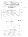
- FIG. 2 is a drawing of a time line for synchronizing a measurement in the communication system as described in various representative embodiments of the present patent document.
- FIG. 3 is a flow chart of a method for synchronizing a measurement in the communication system as described in various representative embodiments of the present patent document.
- FIG. 4 is a flow chart of a portion of the method for synchronizing a measurement in the communication system as described in various representative embodiments of the present patent document.
- FIG. 5 is a flow chart of yet another portion of the method for synchronizing a measurement in the communication system as described in various representative embodiments of the present patent document.
- the present patent document relates to a novel method for synchronizing a measurement in a communication system, as for example in a telephone system using Voice over Packet (VoP) technology and in the more popular form of VoP that utilizes the Internet Protocol (IP) and commonly referred to as Voice over IP (VoIP).
- VoIP Voice over Packet
- IP Internet Protocol
- VoIP Voice over IP
- FIG. 1 is a drawing of a communication system as described in various representative embodiments of the present patent document.
- the communication system is telephone system which utilizes Voice over Packet (VoP) technology in its more popular form the Internet Protocol (IP) and commonly referred to as Voice over IP (VoIP).
- VoIP Voice over Packet
- IP Internet Protocol
- VoIP Voice over IP
- a first communication station 105 which in this example is first telephone 105 , is connected to a communication link 110 at a first connection point 115
- a second communication station 106 which in this example is second telephone 106 , is connected to the communication link 110 at a second connection point 116 .
- Voice and other signals from the first communication station 105 are carried to a first gateway 121 , typically located in the telephone system switching office, via a first dedicated communication line 125 .
- the first dedicated communication line 125 carries traffic in both directions between the first communication station 105 and the first gateway 121 .
- an analogue signal which could be a voice signal
- ADC analogue-to-digital converter
- the signal then takes any number of possible physical paths through the network backbone 150 until it arrives at the second gateway 122 .
- the voice data is uncompressed by a second codec 136 and then transformed from digital to analogue data by a second digital-to-analogue converter (DAC) 162 .
- the analogue voice signal is now carried to the second communication station 106 via a second dedicated communication line 126 .
- Signals may also pass through other system components not shown in FIG. 1, as for example jitter buffers which are intended to smooth the flow of the signal.
- Traffic from the second communication station 106 to the first communication station 105 follow a similar, but reverse route.
- a voice or data transmission from the second telephone 106 is first converted to a digital signal by a second analogue-to-digital converter 132 before being compressed by the second codes 136 , and in the second gateway, the signal from the first codes 135 is converted to an analogue signal by a first digital-to-analogue converter (DAC) 161 .
- DAC digital-to-analogue converter
- Signals from the second communication station 106 are carried to the second gateway 122 , typically located in the telephone system switching office, via the second dedicated communication line 126 .
- the second dedicated communication line 126 carries traffic in both directions between the second communication station 106 and the second gateway 122 .
- the analogue signal is transmitted by the second communication station 106 , it is converted to a digital signal by the second analogue-to-digital converter (ADC) 132 , sent through the second codec 136 which compresses the data in the signal, and then transported over the network backbone 150 to the first gateway 121 .
- the signal then takes any number of possible physical paths through the network backbone 150 until it arrives at the first gateway 121 .
- ADC analogue-to-digital converter
- the voice data is uncompressed by the first codec 135 and then transformed from digital to analogue data by the first digital-to-analogue converter (DAC) 161 .
- the analogue voice signal is now carried to the first communication station 105 via the first dedicated communication line 125 .
- the Voice over Packet system just described has advantages in having the capability of carrying more traffic over the same number of lines than was possible in traditional telephone systems. Further, it is no longer necessary to dedicate specific lines in the network backbone 150 for each connection. Traffic can now take any of many routes through the network 150 and many conversations may share the typically large band-width lines in the network backbone 150 .
- the advantage of such a system is the more efficient transport of information.
- the communications that take place in such systems are less noisy than conventional all analogue systems due to the fact that digital rather than analogue data are being transported across the network backbone 150 . Disadvantages include uncertain delays since the messages sent back and forth can take different routes at different times and, therefore, can experience different delays at different times. Once established, however, a route through the network 150 tends to remain the same unless something catastrophic occurs, as for example the failure of a system router or other critical system component.
- a first voice quality tester (VQT) 171 is connected to the communication link 110 at the first connection point 115 and a second voice quality tester (VQT) 172 is connected to the communication link 110 at the second connection point 116 .
- Voice quality can only be assessed if both ends of the connection are evaluated at the same time.
- a test signal is sent across the communication link 110 by the first communication system 105 , but more specifically by the first voice quality tester 171 at the first connection point 115 , and recorded upon reception at the second connection point 116 by a recorder 180 which may be a part of or attached to the second voice quality tester 172 .
- the recorded copy is compared to the copy kept by the second voice quality tester 172 .
- Deviations between the recorded and the original provide an objective measure of the voice clarity of the communication link 110 between first and second communication stations 105 , 106 . Difficulties arise in the determination of the exact point in the recorded signal to begin comparison with the copy of the original test signal. In order to make this determination, the two signals must be examined in a time and resource consuming process. Methods for more efficient synchronization of these two signals, the signal received and recorded by the recorder 180 at the second communication station 106 and the copy of the original test signal maintained by the second voice quality tester 172 , are disclosed herein.
- FIG. 2 is a drawing of a time line 200 for synchronizing a measurement in the communication system as described in various representative embodiments of the present patent document.
- both voice quality testers 171 , 172 Prior to initiating the steps leading to the time line 200 of FIG. 2, both voice quality testers 171 , 172 must be attached to the communication stations 105 , 106 and turned on.
- the recorder 180 is activated at the second communication station 106 and the test signal transmitted from the first communication station 105 at times relative to each other based upon synchronization signals passing between them as will now be described.
- a first synchronization signal is transmitted by the first voice quality tester 171 .
- the first synchronization signal is received by the second voice quality tester 172 at time T 2 .
- the first synchronization signal has a first duration D 1 .
- a second synchronization signal is transmitted by the second voice quality tester 172 .
- the second synchronization signal is received by the first voice quality tester 171 at time T 4 .
- the second synchronization signal has a second duration D 2 .
- a test signal is transmitted by the first voice quality tester 171 .
- Time T 5 occurs at a first time interval I 1 after time T 4 which is the time that the second synchronization signal was received by the first voice quality tester 171 .
- the recorder 180 is placed in record mode at time T 6 which occurs at a second time interval I 2 after time T 2 which is the time that the first synchronization signal is received by the second voice quality tester 172 .
- Alternative embodiments to that shown in FIG. 2 successively repeat transmission of the first and second synchronization signals. Repeating these synchronization signals provide the opportunity for the system to measure the time delays in the system and adjust recorder 180 initiation accordingly and to make appropriate adjustments for jitter, etc. so that the best quality signal can be obtained.
- the repeated synchronization signals should be of various durations that differ from previous signals such that if a signal is missed or if an echo from an earlier signal is received and is strong enough to be mistaken as a synchronization signal, the system will detect this situation and restart the test.
- a reasonable choice is to generate a second first synchronization signal and a second second synchronization signal measuring first and second time intervals I 1 ,I 2 from times T 4 ,T 2 respectively corresponding to the second first and second synchronization signals.
- the choice as to the number of repeated synchronization signals is a trade off between more precisely identifying the time delays involved in the transmission of messages between first and second communication stations 105 , 106 on the one hand and excessive test times on the other.
- the leading edge of the test signal is received by the second voice quality tester 172 and is recorded by the recorder 180 .
- the trailing edge of the test signal arrives at the second communication station 106 , and at time T 9 , the recording is terminated.
- the received test signal duration D 3 is the difference between times T 8 and T 7 .
- Time T 9 occurs at a third time interval I 3 after time T 6 which is the time that the recorder 180 is placed in record mode.
- the relative times shown in FIG. 2 are for illustrative purposes only.
- FIG. 3 is a flow chart of a method 300 for synchronizing a measurement in the communication system as described in various representative embodiments of the present patent document.
- both voice quality testers 171 , 172 must be attached to the communication stations 105 , 106 and turned on.
- the recorder 180 is activated at the second communication station 106 and the test signal transmitted from the first communication station 105 at times relative to each other based upon synchronization signals passing between them as will now be described in terms of the method steps of FIG. 3 .
- Block 303 When the user is ready to perform a voice clarity test, a counter is set to a preselected start value in block 303 . Block 303 then transfers control to block 305 .
- Block 305 the first voice quality tester 171 located with the first communication station 105 transmits a first synchronization signal. Block 305 then transfers control to block 310 .
- Block 310 the first synchronization signal is received by the second voice quality tester 172 located at the second communication station 106 .
- Block 310 then transfers control to block 315 .
- Block 315 the second voice quality tester 172 transmits a second synchronization signal. Block 315 then transfers control to block 320 .
- Block 320 the second synchronization signal is received by the first voice quality tester 171 located at the first communication station 105 . Block 320 then transfers control to block 322 .
- Block 322 the value in the counter is incremented. Block 322 then transfers control to block 323 .
- block 323 transfers control to block 325 . Otherwise, block 323 transfers control to block 305 thus effecting the repeat of blocks 305 through 323 .
- the test signal is transmitted by the first voice quality tester 171 located at the first communication station 105 at the first preselected time interval I 1 following reception of the second synchronization signal by the first voice quality tester 171 .
- Block 325 then transfers control to block 330 .
- the recorder 180 begins recording at the second preselected time interval 12 following reception of the first synchronization signal by the second voice quality tester 172 located at the second communication station 106 .
- the recorder 180 has capability of recording signals received at the second communication station 106 .
- Block 330 then transfers control to block 335 .
- Block 335 the recorder 180 located with the second voice quality tester 172 at the second communication station 106 records the test signal that it receives after the test signal has traversed the communications link 110 . Block 335 , then transfers control to block 340 .
- the recorder 180 is deactivated.
- a correlation algorithm can be initiated to correlate the timing of a copy of the test signal which the second voice quality tester 172 maintains and the recorded copy of the test signal which traversed the communications link 110 .
- the purpose of the correlation is to adjust the relative timing of the recorded copy of the test signal received by the second voice quality tester 172 to match that of the copy of the original test signal maintained by the second voice quality tester 172 .
- FIG. 4 is a flow chart of a portion 400 of the method for synchronizing a measurement in the communication system as described in various representative embodiments of the present patent document.
- FIG. 4 shows in more detail the method steps that would comprise blocks 305 and 315 of FIG. 3 .
- a pseudo-random analogue signal is created which will be used as the synchronization signal. While true white noise could be used as the synchronization signal, a more practical process is to generate the signal using for example the maximum length sequence (MLS) algorithm which is well known in the art. This algorithm generates all possible sequences of one's and zero's in a bit stream of predefined length and arranged in such an order that the resultant combination appears to be white noise. A combination such as this which appears to be random but which in fact is not is referred to herein as pseudo-random. Block 405 then transfers control to block 408 .
- MLS maximum length sequence
- the synchronization signal is transported from its origination, as for example the voice quality tester 171 , to its gateway, as for example the first gateway 121 .
- Block 408 then transfers control to block 410 .
- the synchronization signal is digitized. Periodic sampling of the first synchronization signal generated by the first voice quality tester 171 enables the first analogue-to-digital converter 131 to digitize the first synchronization signal. Block 410 then transfers control to block 415 .
- Block 415 the digitized synchronization signal is compressed. Compression could be effected by for example the first and second codec's 135 , 136 shown in FIG. 1 . Block 415 then transfers control to block 420 .
- Block 420 transmission packets as for example in an IP network are created from the compressed digitized synchronization signal. Block 420 then transfers control to block 425 .
- FIG. 5 is a flow chart of yet another portion 500 of the method for synchronizing a measurement in the communication system as described in various representative embodiments of the present patent document.
- FIG. 5 shows in more detail the method steps that would comprise blocks 310 and 320 of FIG. 3 .
- Block 505 data packets of the synchronization signal are received at a system gateway, as for example the second gateway 122 .
- Block 505 then transfers control to block 510 .
- Block 510 digitized values of the synchronization signal are extracted from the data packets. Block 510 then transfers control to block 515 .
- Block 515 the digitized values are uncompressed. Block 515 then transfers control to block 520 .
- Block 520 the uncompressed digitized values are converted into analogue values, as for example by the second digital-to-analogue converter 162 shown in FIG. 1 .
- Block 520 then transfers control to block 525 .
- the reconstituted analogue synchronization signal is transported from its destination gateway, as for example second gateway 122 , to its final destination, as for example the second voice quality tester 172 .
- Waveforms for synchronization signals other than the pseudo-random chosen are possible. However, it is relatively easy to confirm that a pseudo-random waveform has been received by measuring its intensity. A constant signal level over any arbitrary period of time is expected for the pseudo-random waveform. In representative embodiments, the signal is examined for different time periods in order to confirm that the same signal level is obtained for both time periods.
- codecs do not distort pseudo-random signals as they would pure sine waves as would be found in for example the signaling tones typically found in telephone systems, i.e., the dual tone multi-frequency (DTMF) tones. Typically any distortion which would be added to the pseudo-random waveform would not change the waveform. The “white noise” into the system would be received as substantially unchanged “white noise”.
- the pseudo-random signal generated appears to be random, it is in fact a completely predetermined waveform. As such, correlation down to the bit level could be obtained between the received test signal and the copy of the test signal. This degree of precision, while available, is typically not required for applications such as that described herein.
- the various methods steps disclosed herein may be implemented by means of software procedures, in hardware, or as a combination of hardware and software components.
- all or part of the functionality required for using the invention may be embodied in computer-readable media, such as a computer hard disk, computer random access memory (RAM), compact disks (CDs), or as 3.5 inch diskettes, to be used in programming an information-processing apparatus, as for example a personal computer or dedicated tester which could be for example the Agilent Telegra R Voice Quality Tester comprising part or all of the abilities previously described to perform in accordance with the invention.
Abstract
Description
Claims (16)
Priority Applications (1)
| Application Number | Priority Date | Filing Date | Title |
|---|---|---|---|
| US09/784,428 US6834040B2 (en) | 2001-02-15 | 2001-02-15 | Measurement synchronization method for voice over packet communication systems |
Applications Claiming Priority (1)
| Application Number | Priority Date | Filing Date | Title |
|---|---|---|---|
| US09/784,428 US6834040B2 (en) | 2001-02-15 | 2001-02-15 | Measurement synchronization method for voice over packet communication systems |
Publications (2)
| Publication Number | Publication Date |
|---|---|
| US20020110153A1 US20020110153A1 (en) | 2002-08-15 |
| US6834040B2 true US6834040B2 (en) | 2004-12-21 |
Family
ID=25132431
Family Applications (1)
| Application Number | Title | Priority Date | Filing Date |
|---|---|---|---|
| US09/784,428 Expired - Lifetime US6834040B2 (en) | 2001-02-15 | 2001-02-15 | Measurement synchronization method for voice over packet communication systems |
Country Status (1)
| Country | Link |
|---|---|
| US (1) | US6834040B2 (en) |
Cited By (8)
| Publication number | Priority date | Publication date | Assignee | Title |
|---|---|---|---|---|
| US20020145979A1 (en) * | 2001-04-05 | 2002-10-10 | Michael Baj | QOS testing of a hardware device or a software client |
| US20020167936A1 (en) * | 2001-05-14 | 2002-11-14 | Lee Goodman | Service level agreements based on objective voice quality testing for voice over IP (VOIP) networks |
| US20020167937A1 (en) * | 2001-05-14 | 2002-11-14 | Lee Goodman | Embedding sample voice files in voice over IP (VOIP) gateways for voice quality measurements |
| US20030069011A1 (en) * | 2000-12-26 | 2003-04-10 | France Telecom. | Method and apparatus for evaluating the voice quality of telephone calls |
| US20030179777A1 (en) * | 2001-07-31 | 2003-09-25 | Denton I. Claude | Method and apparatus for programmable generation of traffic streams |
| US20050068056A1 (en) * | 2003-09-30 | 2005-03-31 | Kahkoska James A. | Digital cable toning apparatus and method |
| US20070223454A1 (en) * | 2006-03-24 | 2007-09-27 | Fujitsu Limited | Voice-quality evaluating system, communication system, test management apparatus, and test communication apparatus |
| US7388946B1 (en) | 2003-09-02 | 2008-06-17 | Level 3 Communications, Llc | System and method for evaluating the quality of service in an IP telephony network using call forwarding |
Families Citing this family (6)
| Publication number | Priority date | Publication date | Assignee | Title |
|---|---|---|---|---|
| US7194068B2 (en) * | 2003-08-20 | 2007-03-20 | Agilent Technologies, Inc. | Autonomous voice responder unit |
| US8737571B1 (en) * | 2004-06-29 | 2014-05-27 | Empirix Inc. | Methods and apparatus providing call quality testing |
| US20060093094A1 (en) * | 2004-10-15 | 2006-05-04 | Zhu Xing | Automatic measurement and announcement voice quality testing system |
| US20060245364A1 (en) * | 2005-03-29 | 2006-11-02 | Xing Zhu | Bi-directional continuous voice and video quality testing system with TTMF tones |
| US8107989B2 (en) * | 2008-07-31 | 2012-01-31 | Honeywell International, Inc. | Apparatus and method for transmit power control in a wireless network |
| US10157844B2 (en) * | 2016-11-28 | 2018-12-18 | Taiwan Semiconductor Manufacturing Co., Ltd. | FinFET device having oxide layer among interlayer dielectric layer |
Citations (3)
| Publication number | Priority date | Publication date | Assignee | Title |
|---|---|---|---|---|
| US5436935A (en) * | 1992-09-29 | 1995-07-25 | Ascom Tech Ag. | Process for synchronizing a receiver switching circuit to a received signal containing a pn-code-spread data signal |
| US5805646A (en) * | 1996-10-08 | 1998-09-08 | Ericsson Inc. | Synchronization method, and associated circuitry, for improved synchronization of a receiver with a transmitter using early-late testing during coarse synchronization |
| US6212247B1 (en) * | 1997-09-03 | 2001-04-03 | Conexant Systems, Inc. | Method and apparatus for generating a programmable synchronization signal for a data communication system |
-
2001
- 2001-02-15 US US09/784,428 patent/US6834040B2/en not_active Expired - Lifetime
Patent Citations (3)
| Publication number | Priority date | Publication date | Assignee | Title |
|---|---|---|---|---|
| US5436935A (en) * | 1992-09-29 | 1995-07-25 | Ascom Tech Ag. | Process for synchronizing a receiver switching circuit to a received signal containing a pn-code-spread data signal |
| US5805646A (en) * | 1996-10-08 | 1998-09-08 | Ericsson Inc. | Synchronization method, and associated circuitry, for improved synchronization of a receiver with a transmitter using early-late testing during coarse synchronization |
| US6212247B1 (en) * | 1997-09-03 | 2001-04-03 | Conexant Systems, Inc. | Method and apparatus for generating a programmable synchronization signal for a data communication system |
Cited By (23)
| Publication number | Priority date | Publication date | Assignee | Title |
|---|---|---|---|---|
| US20030069011A1 (en) * | 2000-12-26 | 2003-04-10 | France Telecom. | Method and apparatus for evaluating the voice quality of telephone calls |
| US7206743B2 (en) * | 2000-12-26 | 2007-04-17 | France Telecom | Method and apparatus for evaluating the voice quality of telephone calls |
| US20020145979A1 (en) * | 2001-04-05 | 2002-10-10 | Michael Baj | QOS testing of a hardware device or a software client |
| US7130273B2 (en) | 2001-04-05 | 2006-10-31 | Level 3 Communications, Inc. | QOS testing of a hardware device or a software client |
| US20020167936A1 (en) * | 2001-05-14 | 2002-11-14 | Lee Goodman | Service level agreements based on objective voice quality testing for voice over IP (VOIP) networks |
| US20020167937A1 (en) * | 2001-05-14 | 2002-11-14 | Lee Goodman | Embedding sample voice files in voice over IP (VOIP) gateways for voice quality measurements |
| US8194565B2 (en) | 2001-05-14 | 2012-06-05 | Lee Goodman | Service level agreements based on objective voice quality testing for voice over IP (VOIP) networks |
| US7280487B2 (en) * | 2001-05-14 | 2007-10-09 | Level 3 Communications, Llc | Embedding sample voice files in voice over IP (VOIP) gateways for voice quality measurements |
| US20070127391A1 (en) * | 2001-05-14 | 2007-06-07 | Level 3 Communications, Inc. | Service Level Agreements Based on Objective Voice Quality Testing for Voice Over IP (VOIP) Networks |
| US7173910B2 (en) | 2001-05-14 | 2007-02-06 | Level 3 Communications, Inc. | Service level agreements based on objective voice quality testing for voice over IP (VOIP) networks |
| US7184408B2 (en) * | 2001-07-31 | 2007-02-27 | Denton I Claude | Method and apparatus for programmable generation of traffic streams |
| US20070008897A1 (en) * | 2001-07-31 | 2007-01-11 | Denton I Claude | Method and apparatus for programmable generation of traffic streams |
| US20060280124A1 (en) * | 2001-07-31 | 2006-12-14 | Null Networks Llc | Method and apparatus for programmable generation of traffic streams |
| US7804782B2 (en) | 2001-07-31 | 2010-09-28 | Denton I Claude | Method and apparatus for programmable generation of traffic streams |
| US8072891B2 (en) * | 2001-07-31 | 2011-12-06 | Null Networks Llc | Method and apparatus for programmable generation of traffic streams |
| US20030179777A1 (en) * | 2001-07-31 | 2003-09-25 | Denton I. Claude | Method and apparatus for programmable generation of traffic streams |
| US7388946B1 (en) | 2003-09-02 | 2008-06-17 | Level 3 Communications, Llc | System and method for evaluating the quality of service in an IP telephony network using call forwarding |
| US7242178B2 (en) * | 2003-09-30 | 2007-07-10 | Fluke Corporation | Digital cable toning apparatus and method |
| US20050068056A1 (en) * | 2003-09-30 | 2005-03-31 | Kahkoska James A. | Digital cable toning apparatus and method |
| US20080012573A1 (en) * | 2003-09-30 | 2008-01-17 | Fluke Corporation | Digital cable toning apparatus and method |
| US7598721B2 (en) * | 2003-09-30 | 2009-10-06 | Fluke Corporation | Locating a cable using synchronization portion and data portion of a tone packet of a system |
| US20070223454A1 (en) * | 2006-03-24 | 2007-09-27 | Fujitsu Limited | Voice-quality evaluating system, communication system, test management apparatus, and test communication apparatus |
| US20110071820A1 (en) * | 2006-03-24 | 2011-03-24 | Fujitsu Limited | Voice-quality evaluating system, communication system, test management apparatus, and test communication apparatus |
Also Published As
| Publication number | Publication date |
|---|---|
| US20020110153A1 (en) | 2002-08-15 |
Similar Documents
| Publication | Publication Date | Title |
|---|---|---|
| US6834040B2 (en) | Measurement synchronization method for voice over packet communication systems | |
| Jelassi et al. | Quality of experience of VoIP service: A survey of assessment approaches and open issues | |
| US8379779B2 (en) | Echo cancellation for a packet voice system | |
| US7280487B2 (en) | Embedding sample voice files in voice over IP (VOIP) gateways for voice quality measurements | |
| US6330428B1 (en) | Voice quality performance evaluator and method of operation in conjunction with a communication network | |
| US20060093094A1 (en) | Automatic measurement and announcement voice quality testing system | |
| US20060245364A1 (en) | Bi-directional continuous voice and video quality testing system with TTMF tones | |
| US20020167936A1 (en) | Service level agreements based on objective voice quality testing for voice over IP (VOIP) networks | |
| CN1409930A (en) | Method and apparatus for early detection of DTMF signals in voice transmission over IP network | |
| US6823302B1 (en) | Real-time quality analyzer for voice and audio signals | |
| US8737571B1 (en) | Methods and apparatus providing call quality testing | |
| US20100104049A1 (en) | Dual-rate single band communication system | |
| US8457182B2 (en) | Multiple data rate communication system | |
| CN100499694C (en) | Method and device for testing speech quality | |
| KR100738162B1 (en) | Method for measuring interactive speech quality in VoIP network | |
| US20030220801A1 (en) | Audio compression method and apparatus | |
| CN1592236A (en) | Method and device for testing speech quality | |
| US7050924B2 (en) | Test signalling | |
| EP1557979A1 (en) | Method and device for determining the speech latency across a network element of a communication network | |
| JP4500458B2 (en) | Real-time quality analyzer for voice and audio signals | |
| Denisowski | How does it sound? | |
| Beuran et al. | User-perceived quality assessment for VoIP applications | |
| JP3977784B2 (en) | Real-time packet processing apparatus and method | |
| US20040252813A1 (en) | Tone clamping and replacement | |
| CN100488216C (en) | Testing method and tester for IP telephone sound quality |
Legal Events
| Date | Code | Title | Description |
|---|---|---|---|
| AS | Assignment |
Owner name: AGILENT TECHNOLOGIES INC., CALIFORNIA Free format text: ASSIGNMENT OF ASSIGNORS INTEREST;ASSIGNOR:TOMBERLIN, JEFFREY;REEL/FRAME:011715/0472 Effective date: 20010330 |
|
| STCF | Information on status: patent grant |
Free format text: PATENTED CASE |
|
| FPAY | Fee payment |
Year of fee payment: 4 |
|
| FPAY | Fee payment |
Year of fee payment: 8 |
|
| AS | Assignment |
Owner name: JDS UNIPHASE CORPORATION, CALIFORNIA Free format text: ASSIGNMENT OF ASSIGNORS INTEREST;ASSIGNOR:AGILENT TECHNOLOGIES, INC.;REEL/FRAME:030088/0468 Effective date: 20100501 |
|
| AS | Assignment |
Owner name: VIAVI SOLUTIONS INC., CALIFORNIA Free format text: CHANGE OF NAME;ASSIGNOR:JDS UNIPHASE CORPORATION;REEL/FRAME:037057/0627 Effective date: 20150731 |
|
| FPAY | Fee payment |
Year of fee payment: 12 |
|
| FEPP | Fee payment procedure |
Free format text: PAYOR NUMBER ASSIGNED (ORIGINAL EVENT CODE: ASPN); ENTITY STATUS OF PATENT OWNER: LARGE ENTITY |
|
| AS | Assignment |
Owner name: WELLS FARGO BANK, NATIONAL ASSOCIATION, AS ADMINISTRATIVE AGENT, COLORADO Free format text: SECURITY INTEREST;ASSIGNORS:VIAVI SOLUTIONS INC.;3Z TELECOM, INC.;ACTERNA LLC;AND OTHERS;REEL/FRAME:052729/0321 Effective date: 20200519 |
|
| AS | Assignment |
Owner name: RPC PHOTONICS, INC., NEW YORK Free format text: TERMINATIONS OF SECURITY INTEREST AT REEL 052729, FRAME 0321;ASSIGNOR:WELLS FARGO BANK, NATIONAL ASSOCIATION, AS ADMINISTRATIVE AGENT;REEL/FRAME:058666/0639 Effective date: 20211229 Owner name: VIAVI SOLUTIONS INC., CALIFORNIA Free format text: TERMINATIONS OF SECURITY INTEREST AT REEL 052729, FRAME 0321;ASSIGNOR:WELLS FARGO BANK, NATIONAL ASSOCIATION, AS ADMINISTRATIVE AGENT;REEL/FRAME:058666/0639 Effective date: 20211229 |