US6834848B2 - Atomizer - Google Patents
Atomizer Download PDFInfo
- Publication number
- US6834848B2 US6834848B2 US10/086,403 US8640302A US6834848B2 US 6834848 B2 US6834848 B2 US 6834848B2 US 8640302 A US8640302 A US 8640302A US 6834848 B2 US6834848 B2 US 6834848B2
- Authority
- US
- United States
- Prior art keywords
- slot
- gas
- mixing
- mixture
- atomizer
- Prior art date
- Legal status (The legal status is an assumption and is not a legal conclusion. Google has not performed a legal analysis and makes no representation as to the accuracy of the status listed.)
- Expired - Lifetime, expires
Links
Images


Classifications
-
- F—MECHANICAL ENGINEERING; LIGHTING; HEATING; WEAPONS; BLASTING
- F22—STEAM GENERATION
- F22B—METHODS OF STEAM GENERATION; STEAM BOILERS
- F22B27/00—Instantaneous or flash steam boilers
- F22B27/16—Instantaneous or flash steam boilers involving spray nozzles for sprinkling or injecting water particles on to or into hot heat-exchange elements, e.g. into tubes
-
- B—PERFORMING OPERATIONS; TRANSPORTING
- B01—PHYSICAL OR CHEMICAL PROCESSES OR APPARATUS IN GENERAL
- B01F—MIXING, e.g. DISSOLVING, EMULSIFYING OR DISPERSING
- B01F23/00—Mixing according to the phases to be mixed, e.g. dispersing or emulsifying
- B01F23/10—Mixing gases with gases
- B01F23/12—Mixing gases with gases with vaporisation of a liquid
-
- B—PERFORMING OPERATIONS; TRANSPORTING
- B01—PHYSICAL OR CHEMICAL PROCESSES OR APPARATUS IN GENERAL
- B01F—MIXING, e.g. DISSOLVING, EMULSIFYING OR DISPERSING
- B01F23/00—Mixing according to the phases to be mixed, e.g. dispersing or emulsifying
- B01F23/20—Mixing gases with liquids
- B01F23/21—Mixing gases with liquids by introducing liquids into gaseous media
- B01F23/213—Mixing gases with liquids by introducing liquids into gaseous media by spraying or atomising of the liquids
- B01F23/2132—Mixing gases with liquids by introducing liquids into gaseous media by spraying or atomising of the liquids using nozzles
-
- B—PERFORMING OPERATIONS; TRANSPORTING
- B01—PHYSICAL OR CHEMICAL PROCESSES OR APPARATUS IN GENERAL
- B01F—MIXING, e.g. DISSOLVING, EMULSIFYING OR DISPERSING
- B01F25/00—Flow mixers; Mixers for falling materials, e.g. solid particles
- B01F25/30—Injector mixers
- B01F25/31—Injector mixers in conduits or tubes through which the main component flows
- B01F25/312—Injector mixers in conduits or tubes through which the main component flows with Venturi elements; Details thereof
-
- C—CHEMISTRY; METALLURGY
- C23—COATING METALLIC MATERIAL; COATING MATERIAL WITH METALLIC MATERIAL; CHEMICAL SURFACE TREATMENT; DIFFUSION TREATMENT OF METALLIC MATERIAL; COATING BY VACUUM EVAPORATION, BY SPUTTERING, BY ION IMPLANTATION OR BY CHEMICAL VAPOUR DEPOSITION, IN GENERAL; INHIBITING CORROSION OF METALLIC MATERIAL OR INCRUSTATION IN GENERAL
- C23C—COATING METALLIC MATERIAL; COATING MATERIAL WITH METALLIC MATERIAL; SURFACE TREATMENT OF METALLIC MATERIAL BY DIFFUSION INTO THE SURFACE, BY CHEMICAL CONVERSION OR SUBSTITUTION; COATING BY VACUUM EVAPORATION, BY SPUTTERING, BY ION IMPLANTATION OR BY CHEMICAL VAPOUR DEPOSITION, IN GENERAL
- C23C16/00—Chemical coating by decomposition of gaseous compounds, without leaving reaction products of surface material in the coating, i.e. chemical vapour deposition [CVD] processes
- C23C16/44—Chemical coating by decomposition of gaseous compounds, without leaving reaction products of surface material in the coating, i.e. chemical vapour deposition [CVD] processes characterised by the method of coating
- C23C16/448—Chemical coating by decomposition of gaseous compounds, without leaving reaction products of surface material in the coating, i.e. chemical vapour deposition [CVD] processes characterised by the method of coating characterised by the method used for generating reactive gas streams, e.g. by evaporation or sublimation of precursor materials
- C23C16/4481—Chemical coating by decomposition of gaseous compounds, without leaving reaction products of surface material in the coating, i.e. chemical vapour deposition [CVD] processes characterised by the method of coating characterised by the method used for generating reactive gas streams, e.g. by evaporation or sublimation of precursor materials by evaporation using carrier gas in contact with the source material
-
- C—CHEMISTRY; METALLURGY
- C23—COATING METALLIC MATERIAL; COATING MATERIAL WITH METALLIC MATERIAL; CHEMICAL SURFACE TREATMENT; DIFFUSION TREATMENT OF METALLIC MATERIAL; COATING BY VACUUM EVAPORATION, BY SPUTTERING, BY ION IMPLANTATION OR BY CHEMICAL VAPOUR DEPOSITION, IN GENERAL; INHIBITING CORROSION OF METALLIC MATERIAL OR INCRUSTATION IN GENERAL
- C23C—COATING METALLIC MATERIAL; COATING MATERIAL WITH METALLIC MATERIAL; SURFACE TREATMENT OF METALLIC MATERIAL BY DIFFUSION INTO THE SURFACE, BY CHEMICAL CONVERSION OR SUBSTITUTION; COATING BY VACUUM EVAPORATION, BY SPUTTERING, BY ION IMPLANTATION OR BY CHEMICAL VAPOUR DEPOSITION, IN GENERAL
- C23C16/00—Chemical coating by decomposition of gaseous compounds, without leaving reaction products of surface material in the coating, i.e. chemical vapour deposition [CVD] processes
- C23C16/44—Chemical coating by decomposition of gaseous compounds, without leaving reaction products of surface material in the coating, i.e. chemical vapour deposition [CVD] processes characterised by the method of coating
- C23C16/448—Chemical coating by decomposition of gaseous compounds, without leaving reaction products of surface material in the coating, i.e. chemical vapour deposition [CVD] processes characterised by the method of coating characterised by the method used for generating reactive gas streams, e.g. by evaporation or sublimation of precursor materials
- C23C16/4486—Chemical coating by decomposition of gaseous compounds, without leaving reaction products of surface material in the coating, i.e. chemical vapour deposition [CVD] processes characterised by the method of coating characterised by the method used for generating reactive gas streams, e.g. by evaporation or sublimation of precursor materials by producing an aerosol and subsequent evaporation of the droplets or particles
-
- F—MECHANICAL ENGINEERING; LIGHTING; HEATING; WEAPONS; BLASTING
- F16—ENGINEERING ELEMENTS AND UNITS; GENERAL MEASURES FOR PRODUCING AND MAINTAINING EFFECTIVE FUNCTIONING OF MACHINES OR INSTALLATIONS; THERMAL INSULATION IN GENERAL
- F16K—VALVES; TAPS; COCKS; ACTUATING-FLOATS; DEVICES FOR VENTING OR AERATING
- F16K27/00—Construction of housing; Use of materials therefor
- F16K27/003—Housing formed from a plurality of the same valve elements
-
- F—MECHANICAL ENGINEERING; LIGHTING; HEATING; WEAPONS; BLASTING
- F22—STEAM GENERATION
- F22B—METHODS OF STEAM GENERATION; STEAM BOILERS
- F22B27/00—Instantaneous or flash steam boilers
- F22B27/14—Instantaneous or flash steam boilers built-up from heat-exchange elements arranged within a confined chamber having heat-retaining walls
-
- B—PERFORMING OPERATIONS; TRANSPORTING
- B01—PHYSICAL OR CHEMICAL PROCESSES OR APPARATUS IN GENERAL
- B01F—MIXING, e.g. DISSOLVING, EMULSIFYING OR DISPERSING
- B01F2101/00—Mixing characterised by the nature of the mixed materials or by the application field
- B01F2101/58—Mixing semiconducting materials, e.g. during semiconductor or wafer manufacturing processes
-
- B—PERFORMING OPERATIONS; TRANSPORTING
- B67—OPENING, CLOSING OR CLEANING BOTTLES, JARS OR SIMILAR CONTAINERS; LIQUID HANDLING
- B67D—DISPENSING, DELIVERING OR TRANSFERRING LIQUIDS, NOT OTHERWISE PROVIDED FOR
- B67D2210/00—Indexing scheme relating to aspects and details of apparatus or devices for dispensing beverages on draught or for controlling flow of liquids under gravity from storage containers for dispensing purposes
- B67D2210/00028—Constructional details
- B67D2210/00047—Piping
- B67D2210/0006—Manifolds
-
- Y—GENERAL TAGGING OF NEW TECHNOLOGICAL DEVELOPMENTS; GENERAL TAGGING OF CROSS-SECTIONAL TECHNOLOGIES SPANNING OVER SEVERAL SECTIONS OF THE IPC; TECHNICAL SUBJECTS COVERED BY FORMER USPC CROSS-REFERENCE ART COLLECTIONS [XRACs] AND DIGESTS
- Y10—TECHNICAL SUBJECTS COVERED BY FORMER USPC
- Y10T—TECHNICAL SUBJECTS COVERED BY FORMER US CLASSIFICATION
- Y10T137/00—Fluid handling
- Y10T137/8593—Systems
- Y10T137/877—With flow control means for branched passages
- Y10T137/87885—Sectional block structure
Definitions
- the present invention relates, in general, to a fluid delivery system. More particularly, this invention provides an integrated fluid delivery system (IFDS) for providing high purity fluid streams, such as for a wafer processing chamber.
- IFDS integrated fluid delivery system
- High purity fluid delivery systems are employed in demanding manufacturing environments such as the semiconductor manufacturing industry.
- the delivery systems are designed to precisely dispense fluids which may be hazardous in nature (i.e., corrosive, poisonous) and/or expensive.
- various stages such as low pressure chemical vapor deposition (LPCVD), oxidation, and plasma enhanced chemical vapor deposition (PECVD), require corrosive precursors such as boron, silicon and phosphorous to be delivered to a wafer processing chamber for the manufacture of semiconductor devices.
- LPCVD low pressure chemical vapor deposition
- PECVD plasma enhanced chemical vapor deposition
- FIG. 1 a typical prior art liquid delivery system 5 .
- Liquid delivery system 5 utilizes a conduit assembly 7 which employs a plurality of conduit sections 10 , high integrity welds (not shown) and flow devices 12 for delivering high purity liquid streams from system 5 .
- Flow devices 12 can be any device known in the art for processing a fluid, but typically include flow controllers, valves, filters and pressure transducers. As shown in FIG.
- conduit based system 7 requires a large degree of available area inside the cabinet of liquid delivery system 5 .
- a particularly hard to reach component or weld requires maintenance and/or replacement, a significant portion of system 7 would need to be disassembled.
- conduit system 7 is complex and costly to assemble and operate.
- conduit system 7 has a higher overall resistance to fluid flow than lesser complex systems, thus an increased “down time” is required to purge the system of fluids where necessary.
- fluid delivery systems may comprise a flow controller.
- flow controllers couple a sensor for measuring flow volume with a valve for adjusting flow volume. Measuring the flow volume of an entire fluid stream, however, can lead to long response time.
- Some flow controllers employ a fluid bypass, measuring the flow volume of a small portion of the flow and inferring the flow volume in the bypass.
- These flow controllers employ methods for maintaining the necessary pressure differential that are expensive, have high part counts that add tolerances and cost, or are difficult to manufacture yielding inadequate accuracy or repeatability. Examples of such bypass flow controllers include those using a bundle of tubes or a sintered metal slug.
- atomizing and/or vaporizing a liquid in a gas stream is often necessary in high purity fluid processing applications. For example, these processes may be employed to deposit high-purity, metal oxide films on a substrate.
- the liquid mixtures may also be utilized for spray coating, spin coating and sol-gel deposition of materials.
- chemical vapor deposition (CVD) is an increasingly utilized high purity fluid delivery process for forming solid materials, such as coatings or powders by way of reactants in a vapor phase.
- a reactant vapor is created by heating a liquid to an appropriate temperature and bubbling a flow of carrier gas through the liquid (i.e. high purity fluid stream) to transport the vapor into a CVD chamber.
- a gas stream and liquid stream are introduced into a single channel or conduit at a T-junction.
- the CVD system pumps a fluid stream at a steady, controlled rate into a hot region which may include ultrasonic energy for effecting the mixture components.
- this technique creates a dead volume of material upon discontinuance of the process. Further, bubbling can often be an unpredictable method of vaporization, in which the precise quantity of the liquid reactant is difficult to control.
- the present invention provides an atomizer for precisely combining separate gas and liquid streams.
- a base member of the atomizer has a mixing slot formed therein for producing a venturi effect at a mixing point.
- the mixing slot has a gas input side and a mixture side.
- a liquid inlet is in fluidic communication with the mixing slot.
- the mixing point is defined by the junction of the liquid inlet to the mixing slot.
- a gas stream inlet is in fluidic communication with the gas input side of the mixing slot.
- a mixture outlet is in fluidic communication with the mixture side of the mixing slot.
- the gas stream flowing into the mixing point is accelerated by the tapered mixing slot, drawing portions of the liquid into the gas stream by venturi effect to produce a mixture of atomized liquid and gas in a generally laminar flow.
- the atomized mixture of gas and liquid streams is presented at the mixture outlet.
- FIG. 1 is a perspective view of a prior art Fluid Delivery System
- FIG. 2 is a perspective view of the manifolded fluid delivery system in accordance with one embodiment of the present invention
- FIG. 3 is an exploded view of the manifold assembly of the fluid delivery system in accordance with FIG. 2;
- FIG. 4 is a perspective view of the manifold assembly of FIG. 3 showing seamless slots in phantom;
- FIG. 5 is a sectional view of the manifolded fluid delivery system of FIGS. 1-4 taken along lines 3 — 3 of FIG. 3;
- FIG. 6A is an enlarged view of the area designated by reference numeral 27 of FIG. 4.;
- FIG. 6B is a sectional view taken along lines 6 B of FIG. 6A;
- FIG. 7 is a system schematic of the manifolded fluid delivery system of FIG. 2;
- FIG. 8 is a bottom exploded view of the manifold assembly of a multilayered manifolded fluid delivery system in accordance with one embodiment of the present invention.
- FIG. 9 is a longitudinal sectional view of a flow controller for use in an integrated fluid delivery system according to one embodiment of the present invention.
- FIG. 10A is an exploded perspective view of a sub-assembly of the flow controller of FIG. 9;
- FIG. 10B is an exploded perspective view of a sensor channel for the flow controller of FIG. 9;
- FIG. 11 is a system schematic of the embodiment of the present invention shown in FIG. 9;
- FIG. 12 is a top view of a mixing slot of an atomizer in accordance with an embodiment of the present invention.
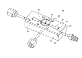
- FIG. 13 is an exploded view of an atomizer/vaporizer in accordance with an exemplary embodiment of the present invention.
- FIG. 14 is a heat exchanger for use in an integrated fluid delivery system in accordance with an embodiment of the present invention.
- an integrated fluid delivery system IFDS
- the fluid streams are of high purity.
- the high purity fluid streams are typically utilized to manufacture semiconductor devices and typically process such fluids as silicon, boron and phosphorous precursors for delivery to a processing destination, such as a wafer processing chamber.
- a processing destination such as a wafer processing chamber.
- Fluid delivery system 15 includes a first modular manifold or “base” 16 for internally channeling the high purity fluid streams along seamless integrated slots 18 (shown best in FIG. 3) formed therein.
- base 16 is a substantially planar, rectangular substrate or plate having first and second surfaces 20 and 22 , respectively.
- base 16 is formed of stainless steel type 316 L VAR (low carbon vacuum arc re-melt) selected for its high corrosion resistance.
- stainless steel type 316 L VAR low carbon vacuum arc re-melt
- the thickness of base 16 is suitable to the application and/or volume of chemicals to be processed therethrough.
- Interconnects 24 are mounted to base 16 via a mounting means, such as bolts (not shown), that are positioned through mounting holes 26 .
- mounting bolts are bolted to threaded interconnect apertures 28 .
- interconnects 24 are removable to allow for repair, maintenance, replacement or redesign of the IFDS and/or its component parts.
- base 16 includes at least one, and typically a plurality of seamless slots 18 (i.e., integrated seamless slots), interconnect apertures 28 (FIG. 4 ), and slot porting apertures 30 (FIG. 4) that are all formed on at least one of two major surfaces or faces thereof.
- slot porting apertures 30 are metallic sealed. Other materials may be suitable for the seals, depending upon the application.
- Interconnect apertures 28 which may be threaded are arranged in a flow device footprint adapted for receiving an interconnect for mounting a corresponding flow device 12 .
- One or both of first and second surfaces 20 and 22 can include seamless slots 18 .
- Seamless slots 18 are provided to consolidate a system schematic, such as shown in FIG. 7 onto surfaces 20 and/or 22 of base 16 for providing a modular manifold component.
- the depth of slots 18 is suitable to the application and/or volume of chemicals to be processed therethrough.
- the system schematic is confined to a first surface 20 and seamless slots 18 are generally substantially elliptical in cross section.
- seamless slots 18 are conical in cross section truncated with a tangential rounded radius as shown in FIG. 5 .
- Seamless slots 18 may be chemically etched and polished to avoid particulate entrapment.
- seamless slots 18 are polished down to less than 16 rms for removing the grain structure of the metal surface of base 16 .
- the metal surface of base 16 can be polished by extruding a polymer loaded with abrasives through base 16 at a high pressure through the use of polyurethane mill tooling.
- the unique shape of slots 18 is designed to complement the tooling for finishing purposes. Rectangular slots diminish the polishing ability of the mill tooling as rectangular slots have sharp corners that are difficult to access.
- seamless slots 18 may be formed by machining or other methods known in the art.
- seamless slots 18 include, along surfaces thereof, first slot porting apertures 30 extending from a surface of seamless slots 18 through to another base surface ( 22 in FIG. 4 ), for channeling high purity fluid streams therethrough.
- slot porting apertures 30 are finished with a detail 32 or “counterbore” to receive a corrosion-resistant seal.
- a corrosion-resistant seal such as a z-seal or c-seal, is used (in an exemplary embodiment, but not shown) upon connection of a corresponding flow device 12 or pneumatic control line.
- Corrosion-resistant seals as used in an exemplary embodiment, require a higher tolerance finish (i.e., less than 16 rms) than that used for elastomeric fittings.
- the specifics of machining the appropriate finish for receiving the selected commercially available seal is understood by those skilled in the art. In some applications, it may be possible to use non-metallic, corrosion-resistant seals.
- interconnects 24 are provided between both slot porting apertures 30 and a desired flow device 12 .
- Interconnects 34 which may be attached to a low leakage fitting 36 (such as a VCR fitting manufactured by Swagelok Company of Solon, Ohio) as a single piece, are also provided between porting apertures 30 and desired flow device 12 .
- Interconnect 34 is mounted to base 16 via mounting apertures 38 (bolts not shown).
- Interconnects 24 are typically commercially available fittings such as those manufactured by Swagelok Company of Solon, Ohio having a detail corresponding to that of apertures 30 for seating the corrosion-resistant seal.
- Base 16 receives interconnects 24 by way of bolting through interconnect apertures 28 .
- a commercially available corrosion-resistant seal (not shown) is constructed of nickel and is interposed between apertures 30 and interconnect 24 for forming a compression fitting.
- the material of the seal should be a softer metal with respect to base 16 so that upon seating interconnect 24 on base 16 the seal is compressed and deforms to seal the connection upon bolting or other securing means.
- a face plate 40 is shown in FIG. 3, having a first and second surface. Face plate 40 is sealed or joined to first surface 20 of base 16 for enclosing seamless slots 18 . Face plate 40 can be sealed to either first or second surface 20 or 22 of base 16 depending upon the application.
- a brazing medium 42 is disposed between base 16 and faceplate 40 and is utilized to seal face plate 40 to a desired surface of base 16 by brazing. In an exemplary embodiment, a nickel brazing medium 42 is used for the brazing process and base 16 is secured to face plate 40 by vacuum brazing. In this way, face plate 40 is joined with base 16 , so that a first surface of face plate 40 abuts a surface (such as first surface 20 ) of base 16 .
- Face plate 40 may additionally include corrosion-resistant sealed plate porting apertures 44 positioned to overlay slots 18 of base 16 .
- seamless slots 18 can be accessed by a processing destination such as a wafer processing chamber through or from flow device 12 .
- Plate porting apertures 44 are likewise finished with a detail 32 (as shown in slot porting apertures 30 in FIGS. 6A and 6B) or “counterbore” to receive a corrosion-resistant seal (such as a z-seal or c-seal, not shown) upon connection of a corresponding flow device or pneumatic control line to introduce the fluid streams to base 16 .
- the present invention can be practiced without employing corrosion-resistant sealed plate porting apertures 44 .
- the thickness of face plate 40 is a matter of design choice for maintaining non-deformity when securing instrumentation to any resident plate porting apertures 44 .
- base 16 receives each of the high purity fluid streams at a corresponding corrosion-resistant sealed slot porting aperture 30 for transporting a fluid along seamless slots 18 .
- Corrosion-resistant sealed porting apertures 30 receive, upon connection of a corresponding flow device or pneumatic control line or the like, fluid streams for transport of one or more fluids through seamless slots 18 of base 16 .
- Slot porting apertures 30 are in fluidic communication with additional slot porting apertures located along seamless slots 18 , as well as plate porting apertures 44 for channeling high purity fluid streams between slots in different bases. In embodiments where face plate 40 may not employ plate porting apertures 44 , fluid would flow along seamless slots 18 between corresponding slot porting apertures 30 . Once mated to an interconnect fitting 24 , fluid device 12 is in fluidic communication with a corresponding one of the high purity liquid streams of base 16 .
- base 16 provides a modular system schematic for dispensing the fluid streams from integrated fluid delivery system 15 to processing destination such as a wafer processing chamber or other device requiring fluid streams.
- a second base 16 B is provided as shown in FIG. 8 having similar details as base 16 .
- the features of second base 16 B are identified by a reference numeral followed by the letter “B”.
- Second base 16 B also has a first and second surface 20 B and 22 B respectively.
- Second base 16 B also includes integrated seamless slots 18 B formed thereon for channeling a fluid stream therethrough.
- Second seamless slots 18 B include, along surfaces thereof, second slot porting apertures (not shown) which are corrosion-resistant sealed porting apertures extending from the surfaces of the second slots 18 B through the second base 16 B.
- Second base 16 B is sealed to an available side of face plate 40 in the same manner as that of the embodiment shown in FIG. 3 .
- Plate porting apertures 44 overlay the slot porting apertures of the integrated slots 18 B and the faceplate is interposed between first base 16 and second base 16 B so that interconnect apertures 28 and 28 B are in alignment.
- slot porting apertures in second base plate 16 B are in fluidic communication with slot porting apertures 30 which are also through first slots 18 and second slots 18 B for channeling fluid streams therebetween.
- a second face plate (not shown) is connected to first surface 20 B of base 16 B for sealing slots 18 B. It will be understood by those skilled in the art that any number of base sections 16 can be layered in this manner depending upon the particular application and that the invention described herein is not limited to the illustration but used above for explanatory purposes only.
- base 16 C is interconnected with a flow processing device to form a flow controller 46 .
- a liquid flow controller assembly 46 employs a base 16 C and an interconnect plate 48 .
- base 16 C includes a seamless slot 18 C (best shown in FIG. 9) between base 16 C and interconnect plate 48 .
- base 16 C and interconnect plate 48 are joined together by a brazing medium 42 using a vacuum brazing process.
- base 16 C can be vacuum brazed, at slot face 20 C directly to second face 45 ( shown in FIG. 10A) of interconnect plate 48 of liquid flow controller assembly 46 .
- Seamless slots 18 C may be formed by machining, etching, or other processes known in the art.
- Base may be a plate (or slot plate) having two opposing surfaces or faces, one of these faces being slot face 20 C. In this way, slot face 20 C and second face 45 abut so that seamless slot 18 C is sealed by the abutment.
- Porting apertures 50 are formed within interconnect plate 48 positioned to align with seamless slot 18 C and extending to the first face 43 of interconnect plate 48 to allow the flow of liquid into and out of, a formed sensor channel 52 (discussed below).
- porting apertures 50 are corrosion-resistant sealed similar to those corrosion-resistant sealed apertures previously discussed herein. Porting apertures 50 may provide for a portion of the liquid stream to flow into and through the sensor channel of the flow controller.
- porting apertures 50 may be finished with a detail 32 or “counterbore.”
- Detail 32 is provided for receiving a corrosion-resistant seal (such as a z-seal or c-seal not shown) upon connection of a corresponding flow device or pneumatic control line to introduce or outlet, fluid streams between base 16 C.
- a corrosion-resistant seal such as a z-seal or c-seal not shown
- Flow controller 46 includes a sensor channel 52 (best shown in FIG. 9) for providing a pathway for a fluid stream of base 16 C.
- Sensor channel 52 in sensor area 56 carries a portion of the fluid stream transported into base 16 C, with the remainder to be carried along seamless slot 18 C.
- Sensor channel 52 is provided for measuring a change in temperature or temperature gradient ( ⁇ T) of the portion of fluid flowing therein across points A and B in FIG. 11 .
- Sensor channel 52 comprises a tube section in fluid communication with seamless slot 18 C through porting apertures 50 in interconnect plate 48 .
- sensor channel 52 extend downwardly from seamless slot 18 C through a sensor plate 49 and into a sensor area 56 of a sensor housing 61 , such that sensor channel 52 is at a lower elevation than seamless slot 18 C.
- Two temperature sensors 57 are mounted on sensor channel 52 with a heater 59 is mounted on the sensor channel between the temperature sensors.
- the sensors and heater comprise wire windings wrapped about the tubing. The heater transfers heat to the fluid to raise the fluid temperature up to 30 degrees Celsius.
- the fluid temperature is raised about 5 degrees Celsius to avoid degradation of certain precursors that may be used with flow controller 46 .
- the sensor channel 52 extends downwardly to reduce blockage of the sensor channel by gas bubbles carried in the fluid stream.
- buttons 53 are welded to the ends of sensor channel 52 .
- Buttons 53 are positioned in counterbores in sensor plate 49 , and corrosion-resistant seals are compressed between buttons 53 and interconnect plate 48 .
- Spacers 55 may be positioned inside the corrosion-resistant seals. Then sensor plate 49 is fastened to interconnect plate 48 , such as with bolts, and sensor housing 61 is fastened to sensor plate 49 .
- Slot porting aperture 51 is formed in seamless slot 18 C, extending through base 16 C and providing fluid communication between seamless slot 18 C and flow control valve 54 .
- Flow control valve 54 is operably connected to temperature sensors 57 .
- the temperature difference ( ⁇ T) infers the flow through seamless slot 18 C, and this temperature difference is used to generate an output signal voltage.
- the flow controller 46 can be used to adjust the mass flow through the flow controller 46 by adjusting the opening of flow control valve 54 .
- Control electronics adjust the opening of flow control valve 54 until the output signal voltage is equal to a predetermined set-point in the control electronics corresponding to a desired mass flow rate.
- the set-point is determined by a variable resistor, such as a potentiometer.
- Flow control valve 54 may be a suitable valve for the particular application that can be electronically adjusted to provide a variable flow rate.
- flow control valve 54 is a piezotranslator, in which stacked ceramic disks press against a flexible metal diaphragm to open or close the diaphragm against apertures in a fluid pathway. The pressure applied by the ceramic disks is proportional to a voltage applied to them. The flow rate is determined by the gap between the diaphragm and the flat surface having the apertures in it (up to about 0.002 inches in an exemplary flow control valve).
- Inlet 58 into base 16 C is a high pressure inlet which branches into two separate pathways.
- the first pathway is seamless slot 18 C for providing a bypass pathway or channel.
- the second pathway is sensor channel 52 .
- Flow valve 54 is in fluidic communication with seamless slot 18 C for receiving the portion of fluid flowing through sensor channel 52 (which is proportional to the flow through seamless slot 18 C) and the portion of fluid flowing through seamless slot 18 C.
- Seamless slot 18 C provides a pressure drop from points 1 to 2 in FIG. 11 .
- Sensor channel 52 and seamless slot 18 C are in fluidic communication with a low pressure outlet 60 , through control valve 54 .
- the change in temperature across points A and B of sensor channel 52 corresponds to an actual fluid flow through the flow controller 46 and has a very low response time on the order of 3 seconds or less. This is an improvement over the simple sampling of a single fluid stream as such an arrangement yields very slow response time (e.g., 20 seconds). This arrangement provides a fast and accurate reading of fluid flow.
- This mass flow controller can be a modular component for use in an IFDS.
- an atomizer for combining separate gas and liquid streams is provided.
- This atomizer can be a modular component for use in an IFDS.
- a mixing point is defined by the junction of a liquid inlet to a mixing slot.
- a gas stream inlet is in fluidic communication with a side of the mixing slot.
- a mixture outlet defines the remaining side of the mixing slot.
- a gas stream flowing into the mixing point is accelerated to a high velocity, reducing pressure for drawing the liquid into the gas stream by venturi effect.
- FIG. 12 There is shown in FIG. 12 a mixing slot 62 of an atomizer 64 for combining separate gas and liquid streams.
- Mixing slot 62 has a mixing point 66 for atomizing a liquid stream into a gas stream.
- a stream of the high purity mixture of fluid and gas are utilized, for example, to deposit high-purity, metal oxide films on a substrate in processes such as semiconductor manufacturing.
- the liquid and gas mixtures may also be utilized for spray coating, spin coating and sol-gel deposition of materials.
- the present invention is applicable to any number of fluid/gas stream chemistry and/or manufacturing environments.
- Atomizer 64 includes a base member 16 D having a mixing slot 62 formed in a face thereof for producing a venturi effect at a mixing point 66 .
- base 16 D is a substantially planar, rectangular substrate formed of type 316 stainless steel (low carbon vacuum arc re-milled) LVAR selected for its high corrosion resistance.
- Other shapes of base 16 D can be used depending on the application, and other materials suitable for the fluids/gases used in a particular application may be used as will be understood by those skilled in the art.
- the thickness of base 16 D is suitable to the application and/or volume of chemicals to be processed therethrough.
- An exemplary base member structure is shown in FIG. 12 and described below.
- Mixing slot 62 may be formed by machining, etching, or other processes known in the art.
- Mixing slot 62 of base member 16 D has a gas input side 82 and a mixture side 88 .
- mixing slot 62 is generally hourglass shaped.
- Gas input side 82 and mixture side 88 are each substantially triangular in shape and are in fluid communication through a throat joining their respective apices.
- a mixing point 66 is located at the throat of the hourglass shape.
- the venturi effect is caused by the narrowing of the gas input side 82 and mixture side 88 of the hourglass shape, which increases the velocity of the gas lowering the pressure and drawing liquid into the gas stream.
- the particular fluid dynamics of the venturi effect will be understood by those skilled in the art.
- a liquid inlet 80 is in fluidic communication with mixing point 66 of mixing slot 62 .
- Mixing point 66 is defined by the junction of liquid inlet 80 and mixing slot 62 .
- a gas stream inlet 84 is in fluidic communication with gas input side 82 of mixing slot 62 .
- a valve (not shown) proximate to mixing point 66 may be provided for controlling the introduction of a liquid stream through liquid inlet 80 and eliminating dead volume upon discontinuance of the process as it controls the entry of the liquid stream at mixing point 66 .
- a mixture outlet 90 is in fluidic communication with mixture output side 88 of mixing slot 62 .
- a face plate 40 D abuts base member 16 D sealing mixing slot 62 .
- the atomizer described herein may be provided as a modular component for use in an IFDS.
- a mixing slot for atomizing a liquid into a gas stream, and a mixture heating slot for vaporizing the atomized liquid in the mixture are combined to form a vaporizer 64 E.
- a base member 16 E has a mixing slot 62 , as described above, formed in one of its faces for producing a venturi effect at a mixing point 66 .
- a gas slot 70 and a mixture heating slot 72 are formed in base member 16 E in fluid communication with the gas input side 82 and mixture side 88 , respectively, of mixing slot 62 .
- Base member 16 E internally channels gas and fluid streams along seamless slots 70 and 72 .
- base 16 E is a substantially planar, rectangular substrate having first and second surfaces 74 and 78 , respectively.
- Other shapes of base 16 E can be used depending on the application.
- base 16 E is formed of stainless steel type 316 LVAR (low carbon vacuum arc re-milled) selected for its high corrosion resistance.
- Other materials suitable for the fluids/gases used in a particular application will be understood by those skilled in the art.
- the thickness of base 16 E is suitable to the application and/or volume of chemicals to be processed therethrough.
- gas slot 70 is provided having a gas inlet side 84 and a gas outlet side 86 .
- Gas outlet side 86 of gas slot 70 is connected to gas input side 82 of mixing slot 62 .
- gas slot 70 is a serpentine pathway for heating the gas stream to either a predetermined or adjustable temperature. The degree of heating is dependent upon the length of the pathway and type of gas, as well as other factors (e.g., gas velocity and temperature difference between gas and base).
- the gas stream flowing into a mixing slot may be heated to reduce the heat required to be added to the mixture stream for vaporization.
- FIG. 13 shows mixture heating slot 72 in fluidic communication with mixture side 88 of mixing slot 62 .
- Mixture heating slot 72 has a mixture inlet 90 and a mixture outlet 92 .
- Mixture heating slot 72 is connected to mixture side 88 of mixing slot 62 .
- a gas stream flows through gas slot 70 , into mixing slot 62 , and then to mixing point 66 .
- the velocity of the gas stream is increased in velocity by the narrowing of gas input side 82 lowering the pressure at mixing slot 62 and generating a venturi effect. In this way, portions of the liquid stream are drawn into the gas stream to provide an atomized mixture of gas and liquid streams to mixture heating slot 72 .
- the mixture stream is heated in mixture heating slot 72 , vaporizing the atomized liquid in the mixture to form a vapor mixture which exits base 16 E via outlet 92 .
- gas slot 70 and mixture heating slot 72 are sealed within base 16 E by a pair of faceplates 40 .
- a brazing medium (not shown) may be utilized to seal face plates 40 to surfaces 74 and 78 of base 16 E by brazing.
- the brazing process is similar to the brazing process described herein.
- a nickel medium is used for the brazing process and base 16 E is secured to face plates 40 by vacuum brazing.
- faceplates 40 may be sealed to the base 16 E by way of interconnect apertures 98 provided to receive bolts (not shown).
- face plates 40 may include porting apertures 100 for importing and exporting fluid and/or gas streams directly to base 16 E, such as from a flow control valve (not shown).
- Porting apertures 100 are sealed with a corrosion-resistant seal in an exemplary embodiment. While vaporizer 64 E is shown having a serpentine layout, it is recognized by those skilled in the art that gas slot 70 and mixture heating slot 72 may be any number of layouts for heating the gas and mixture, or be essentially straight where necessary.
- a heat exchanger is provided in fluidic communication with a mixture stream, such as at mixture side 88 of mixing slot 62 of an atomizer as described above.
- the heat exchanger can encompass a single continuous pathway, such as mixture heating slot 72 , as shown in FIG. 13 .
- the heat exchanger may be in fluid communication with the outlet of an atomizer as described herein.
- the heat exchanger provides heat to an atomized liquid stream vaporizing the atomized liquid. Atomizing the liquid in a mixed stream of gas and liquid prior to vaporization lowers the temperature of vaporization, which may reduce degradation of certain liquid precursors.
- the heat exchanger may be a serpentine pathway, as shown in FIG. 13, for heating the atomized mixture to a predetermined temperature for vaporization.
- the degree of heating is dependent, in part, upon the length of the pathway and atomized chemistry.
- Other heat exchanger configuration are possible and are within the scope of the invention.
- Heat exchanger 94 F may be used to vaporize atomized liquid in a mixture stream produced by an atomizer 64 or for vaporizing a liquid supplied to the inlet of heat exchanger 94 F which is neither atomized nor mixed with a gas stream.
- Heat exchanger 94 F includes a base 16 F with an inlet 102 in fluid communication with a mixture outlet of an atomizer or an unatomized and unmixed liquid stream.
- a distribution slot 104 formed in a slot face 106 of base 16 F is in fluid communication with inlet 102 and a plurality of seamless slots 18 F formed in slot face 106 .
- a plurality of cross-slots 108 are formed in face 106 intersecting the plurality of seamless slots 18 F.
- the cross-sectional area of the seamless slots is small enough to prevent surface tension from beading the liquid, which would reduce contact with the heated surface and reduce efficient heat transfer. Liquid is turned into vapor by the application of heat. If liquid is heated in a single slot or channel, bubbles of vapor can form that will expand rapidly and push slugs of liquid to the outlet, causing spitting.
- the cross-slots allow vapor bubbles to find a path to the outlet without pushing a slug of liquid to the outlet.
- the cross-sectional area of the cross-slots 108 may be larger than the cross-sectional area of the seamless slots 18 F to capture slugs of liquid and further reduce spitting.
Abstract
Description
Claims (17)
Priority Applications (1)
| Application Number | Priority Date | Filing Date | Title |
|---|---|---|---|
| US10/086,403 US6834848B2 (en) | 2001-02-28 | 2002-02-28 | Atomizer |
Applications Claiming Priority (2)
| Application Number | Priority Date | Filing Date | Title |
|---|---|---|---|
| US27194701P | 2001-02-28 | 2001-02-28 | |
| US10/086,403 US6834848B2 (en) | 2001-02-28 | 2002-02-28 | Atomizer |
Publications (2)
| Publication Number | Publication Date |
|---|---|
| US20020148406A1 US20020148406A1 (en) | 2002-10-17 |
| US6834848B2 true US6834848B2 (en) | 2004-12-28 |
Family
ID=23037766
Family Applications (4)
| Application Number | Title | Priority Date | Filing Date |
|---|---|---|---|
| US10/087,057 Expired - Lifetime US6694809B2 (en) | 2001-02-28 | 2002-02-28 | Flow controller |
| US10/087,701 Expired - Lifetime US6604492B2 (en) | 2001-02-28 | 2002-02-28 | Vaporizer |
| US10/087,709 Expired - Lifetime US6892762B2 (en) | 2001-02-28 | 2002-02-28 | Manifolded fluid delivery system |
| US10/086,403 Expired - Lifetime US6834848B2 (en) | 2001-02-28 | 2002-02-28 | Atomizer |
Family Applications Before (3)
| Application Number | Title | Priority Date | Filing Date |
|---|---|---|---|
| US10/087,057 Expired - Lifetime US6694809B2 (en) | 2001-02-28 | 2002-02-28 | Flow controller |
| US10/087,701 Expired - Lifetime US6604492B2 (en) | 2001-02-28 | 2002-02-28 | Vaporizer |
| US10/087,709 Expired - Lifetime US6892762B2 (en) | 2001-02-28 | 2002-02-28 | Manifolded fluid delivery system |
Country Status (6)
| Country | Link |
|---|---|
| US (4) | US6694809B2 (en) |
| EP (4) | EP1374004A2 (en) |
| JP (4) | JP2005506681A (en) |
| AU (1) | AU2002242304A1 (en) |
| DE (3) | DE60215618T2 (en) |
| WO (4) | WO2002068127A2 (en) |
Cited By (4)
| Publication number | Priority date | Publication date | Assignee | Title |
|---|---|---|---|---|
| US20080315017A1 (en) * | 2005-12-16 | 2008-12-25 | Grundfos Nonox A/S | Nozzle With Impinging Jets |
| WO2016025858A1 (en) * | 2014-08-15 | 2016-02-18 | Bowles Fluidics Corporation | Multi-inlet, multi-spray fluidic cup nozzle with shared interaction region and spray generation method |
| US9877514B2 (en) | 2015-09-21 | 2018-01-30 | Cloud V Enterprises | Vaporizer with electronically heated nail |
| US11154876B2 (en) | 2011-04-19 | 2021-10-26 | Dlhbowles, Inc. | Multi-inlet, multi-spray fluidic cup nozzle with shared interaction region and spray generation method |
Families Citing this family (66)
| Publication number | Priority date | Publication date | Assignee | Title |
|---|---|---|---|---|
| WO2002068127A2 (en) | 2001-02-28 | 2002-09-06 | Porter Instrument Company, Inc. | Manifolded fluid delivery system |
| US6964809B2 (en) * | 2002-02-15 | 2005-11-15 | Pedro M. Buarque de Macedo | Large high density foam glass tile |
| JP2003280745A (en) * | 2002-03-25 | 2003-10-02 | Stec Inc | Mass-flow controller |
| US20050103323A1 (en) * | 2003-10-16 | 2005-05-19 | Engdahl Gerald E. | Submerged combustion water heater |
| US20050147749A1 (en) * | 2004-01-05 | 2005-07-07 | Msp Corporation | High-performance vaporizer for liquid-precursor and multi-liquid-precursor vaporization in semiconductor thin film deposition |
| US20050200129A1 (en) * | 2004-03-15 | 2005-09-15 | Bongiorno Louis C. | Aseptic flanged joint |
| US7350833B2 (en) | 2004-03-15 | 2008-04-01 | Bongiorno Louis C | Self-aligning aseptic flanged joint |
| JP2006009969A (en) * | 2004-06-25 | 2006-01-12 | Kitz Sct:Kk | Flow path block for accumulated gas control device and its manufacturing method and accumulated gas control device |
| US20060021574A1 (en) * | 2004-08-02 | 2006-02-02 | Veeco Instruments Inc. | Multi-gas distribution injector for chemical vapor deposition reactors |
| US7822586B2 (en) * | 2004-08-11 | 2010-10-26 | Entegris, Inc. | System and method for optimizing and simulating thermal management systems and predictive flow control |
| US20060052997A1 (en) * | 2004-09-09 | 2006-03-09 | International Business Machines Corporation | Automating identification of critical memory regions for pre-silicon operating systems |
| US7339726B2 (en) * | 2004-12-09 | 2008-03-04 | Epitaxial Technologies | Modulating retroreflector array using vertical cavity optical amplifiers |
| JP4634175B2 (en) * | 2005-02-10 | 2011-02-16 | 三菱重工業株式会社 | Logic plate for high pressure fluid |
| US7871536B2 (en) * | 2005-09-12 | 2011-01-18 | Fujifilm Electronic Materials U.S.A., Inc. | Additives to prevent degradation of cyclic alkene derivatives |
| US7883639B2 (en) * | 2005-09-12 | 2011-02-08 | Fujifilm Electronic Materials, U.S.A., Inc. | Additives to prevent degradation of cyclic alkene derivatives |
| JP2009507837A (en) * | 2005-09-12 | 2009-02-26 | フジフィルム・エレクトロニック・マテリアルズ・ユーエスエイ・インコーポレイテッド | Additives that prevent degradation of cyclic alkene derivatives |
| US7551439B2 (en) * | 2006-03-28 | 2009-06-23 | Delphi Technologies, Inc. | Fluid cooled electronic assembly |
| US8196480B1 (en) | 2006-04-03 | 2012-06-12 | A+ Manufacturing, Llc | Modular sample conditioning system |
| US7752928B1 (en) | 2006-04-03 | 2010-07-13 | A+ Manufacturing, Llc | Modular sample conditioning system |
| US8322232B1 (en) | 2006-04-03 | 2012-12-04 | A+ Manufacturing, Llc | Modular sample conditioning system |
| US7450384B2 (en) * | 2006-07-06 | 2008-11-11 | Hybricon Corporation | Card cage with parallel flow paths having substantially similar lengths |
| DE102006037496B4 (en) * | 2006-08-10 | 2008-08-14 | Compact Dynamics Gmbh | Braking unit for a land vehicle |
| US20080044572A1 (en) * | 2006-08-15 | 2008-02-21 | Loeffler Stephen D | Right-sized vacuum precursor (rsvp) distillation system |
| JP5183935B2 (en) * | 2007-02-26 | 2013-04-17 | Ckd株式会社 | Manufacturing method of flow path block |
| JP5427344B2 (en) * | 2007-05-23 | 2014-02-26 | 株式会社渡辺商行 | Vaporization apparatus and film forming apparatus equipped with vaporization apparatus |
| MX2010003438A (en) * | 2007-10-02 | 2010-04-21 | Philip Morris Prod | Biomarkers and methods for determining sensitivity to vascular endothelial growth factor receptor-2 modulators. |
| JP5202101B2 (en) * | 2008-05-21 | 2013-06-05 | 旭有機材工業株式会社 | Mixing valve and mixing device using the same |
| US8173213B2 (en) | 2008-05-28 | 2012-05-08 | Air Products And Chemicals, Inc. | Process stability of NBDE using substituted phenol stabilizers |
| US9622615B2 (en) | 2008-11-10 | 2017-04-18 | Automatic Bar Controls, Inc. | Touch screen interface for a beverage dispensing machine |
| US9588608B2 (en) | 2008-11-10 | 2017-03-07 | Automatic Bar Controls, Inc. | ADA enabled touch screen interface for a beverage dispensing machine |
| US9271604B2 (en) | 2008-11-10 | 2016-03-01 | Automatic Bar Controls, Inc. | Manifold system for beverage dispenser |
| US9908767B2 (en) | 2008-11-10 | 2018-03-06 | Automatic Bar Controls, Inc. | Beverage dispensing apparatus with presence sensing |
| US20100116842A1 (en) * | 2008-11-10 | 2010-05-13 | Automatic Bar Controls, Inc. | Reconfigurable control panel for a beverage dispenser |
| US8499795B2 (en) * | 2009-11-24 | 2013-08-06 | Keihin Corporation | Solenoid valve device |
| US20110180468A1 (en) * | 2010-01-22 | 2011-07-28 | Michael Foley | Clean filter housing |
| US8528399B2 (en) | 2010-05-21 | 2013-09-10 | The Mercury Iron and Steel Co. | Methods and apparatuses for measuring properties of a substance in a process stream |
| WO2012145606A2 (en) * | 2011-04-20 | 2012-10-26 | Swagelok Company | Fluid processing systems and sub-systems |
| US10442671B2 (en) | 2011-08-29 | 2019-10-15 | Automatic Bar Controls, Inc. | Nozzle with isolation porting |
| US20130153064A1 (en) * | 2011-12-15 | 2013-06-20 | Caterpillar Inc. | Brazed assembly and method of forming |
| JP5973178B2 (en) * | 2012-02-01 | 2016-08-23 | Ckd株式会社 | Liquid control device |
| MX368003B (en) * | 2013-03-27 | 2019-09-13 | Renew Group Private Ltd | Portable oscillating compression system. |
| PL2789909T3 (en) * | 2013-04-12 | 2018-02-28 | RETECH Spółka z o.o. | Steam generator |
| US9657397B2 (en) * | 2013-12-31 | 2017-05-23 | Lam Research Ag | Apparatus for treating surfaces of wafer-shaped articles |
| DE102014001203A1 (en) * | 2014-01-29 | 2015-07-30 | Thermo Electron Led Gmbh | Connecting line system for a laboratory device and / or medical device as well as production method and use thereof |
| US10107490B2 (en) | 2014-06-30 | 2018-10-23 | Lam Research Corporation | Configurable liquid precursor vaporizer |
| US9639094B2 (en) * | 2014-11-12 | 2017-05-02 | Michael D. Palmer | Electronic pneumatic pressure controller |
| US9982341B2 (en) | 2015-01-30 | 2018-05-29 | Lam Research Corporation | Modular vaporizer |
| CN105498596B (en) * | 2015-11-30 | 2018-08-24 | 加通汽车内饰(常熟)有限公司 | A kind of mixing device |
| AR107598A1 (en) | 2016-02-12 | 2018-05-16 | Automatic Bar Controls Inc | NOZZLE WITH INSULATING COMPUTER |
| KR102248120B1 (en) * | 2016-03-24 | 2021-05-04 | 가부시키가이샤 코쿠사이 엘렉트릭 | Vaporizer, substrate processing apparatus and method of manufacturing semiconductor device |
| US10125883B2 (en) * | 2016-05-17 | 2018-11-13 | Tescom Corporation | Methods and apparatus to couple manifold blocks to form a manifold |
| KR102415265B1 (en) * | 2017-04-10 | 2022-06-29 | 버슘머트리얼즈 유에스, 엘엘씨 | Aerosol-free vessel for bubbling chemical precursors in deposition processes |
| US10147597B1 (en) | 2017-09-14 | 2018-12-04 | Lam Research Corporation | Turbulent flow spiral multi-zone precursor vaporizer |
| WO2020213104A1 (en) * | 2019-04-17 | 2020-10-22 | 株式会社Welcon | Vaporizer and method for manufacture thereof |
| US11353117B1 (en) | 2020-01-17 | 2022-06-07 | Vulcan Industrial Holdings, LLC | Valve seat insert system and method |
| US11421679B1 (en) | 2020-06-30 | 2022-08-23 | Vulcan Industrial Holdings, LLC | Packing assembly with threaded sleeve for interaction with an installation tool |
| US11421680B1 (en) | 2020-06-30 | 2022-08-23 | Vulcan Industrial Holdings, LLC | Packing bore wear sleeve retainer system |
| US11384756B1 (en) | 2020-08-19 | 2022-07-12 | Vulcan Industrial Holdings, LLC | Composite valve seat system and method |
| USD986928S1 (en) | 2020-08-21 | 2023-05-23 | Vulcan Industrial Holdings, LLC | Fluid end for a pumping system |
| USD980876S1 (en) | 2020-08-21 | 2023-03-14 | Vulcan Industrial Holdings, LLC | Fluid end for a pumping system |
| USD997992S1 (en) | 2020-08-21 | 2023-09-05 | Vulcan Industrial Holdings, LLC | Fluid end for a pumping system |
| US11391374B1 (en) | 2021-01-14 | 2022-07-19 | Vulcan Industrial Holdings, LLC | Dual ring stuffing box |
| US11912558B2 (en) | 2021-03-12 | 2024-02-27 | Smart Bar Usa Llc | Beverage dispense head assembly |
| US11624450B2 (en) * | 2021-04-29 | 2023-04-11 | Applied Materials, Inc. | Fluid delivery mounting panel and system |
| US11434900B1 (en) | 2022-04-25 | 2022-09-06 | Vulcan Industrial Holdings, LLC | Spring controlling valve |
| US11920684B1 (en) | 2022-05-17 | 2024-03-05 | Vulcan Industrial Holdings, LLC | Mechanically or hybrid mounted valve seat |
Citations (31)
| Publication number | Priority date | Publication date | Assignee | Title |
|---|---|---|---|---|
| US1273356A (en) * | 1915-02-03 | 1918-07-23 | Good Inventions Co | Fuel-supply means for combustion-engines. |
| US2165447A (en) * | 1936-08-06 | 1939-07-11 | Wright Aeronautical Corp | Pressure metering carburetor |
| US2791995A (en) * | 1954-02-15 | 1957-05-14 | Gen Motors Corp | Anti-detonation device for a carburetor |
| US3336013A (en) * | 1965-06-24 | 1967-08-15 | Eryx Corp | Contact heating apparatus and method |
| US3689237A (en) * | 1970-02-19 | 1972-09-05 | North American Utility Constru | Fuel gas pipeline system |
| US3716194A (en) | 1970-09-16 | 1973-02-13 | Economics Lab | Combination high pressure venturi and spray forming nozzle |
| US4048993A (en) * | 1975-06-30 | 1977-09-20 | Dragerwerk Aktiengesellschaft | Humidity exchanger in an apparatus for respiration and anasthesia |
| US4079410A (en) | 1975-12-10 | 1978-03-14 | Semikron Gesellschaft Fur Gleichrichterbau Und Elektronik M.B.H. | Semiconductor rectifier device with improved cooling arrangement |
| US4489570A (en) | 1982-12-01 | 1984-12-25 | The Board Of Trustees Of The Leland Stanford Junior University | Fast cooldown miniature refrigerators |
| US4634559A (en) * | 1984-02-29 | 1987-01-06 | Aluminum Company Of America | Fluid flow control process |
| US4794981A (en) | 1986-04-09 | 1989-01-03 | Nec Corporation | Cooling system |
| US4919853A (en) | 1988-01-21 | 1990-04-24 | The United States Of America As Represented By The United States Department Of Energy | Apparatus and method for spraying liquid materials |
| US5099311A (en) | 1991-01-17 | 1992-03-24 | The United States Of America As Represented By The United States Department Of Energy | Microchannel heat sink assembly |
| US5161089A (en) | 1990-06-04 | 1992-11-03 | International Business Machines Corporation | Enhanced multichip module cooling with thermally optimized pistons and closely coupled convective cooling channels, and methods of manufacturing the same |
| US5218515A (en) | 1992-03-13 | 1993-06-08 | The United States Of America As Represented By The United States Department Of Energy | Microchannel cooling of face down bonded chips |
| US5249740A (en) * | 1990-11-27 | 1993-10-05 | Assoc. De Gestion De L'ecole Francaise De Papeterie Et D'imprimerie | Method for regulating the conditioning of a gas and gas conditioning device |
| US5355942A (en) | 1991-08-26 | 1994-10-18 | Sun Microsystems, Inc. | Cooling multi-chip modules using embedded heat pipes |
| US5495889A (en) | 1993-02-10 | 1996-03-05 | Gec Alsthom Transport Sa | Cooling device for power electronic components |
| US5539617A (en) | 1992-09-22 | 1996-07-23 | Siemens Aktiengesellschaft | Liquid-coolant cooling element |
| US5655290A (en) | 1992-08-05 | 1997-08-12 | Fujitsu Limited | Method for making a three-dimensional multichip module |
| US5675974A (en) | 1994-01-18 | 1997-10-14 | Robert Bosch Gmbh | Heat exchanger |
| US5692558A (en) | 1996-07-22 | 1997-12-02 | Northrop Grumman Corporation | Microchannel cooling using aviation fuels for airborne electronics |
| US5826643A (en) | 1996-06-07 | 1998-10-27 | International Business Machines Corporation | Method of cooling electronic devices using a tube in plate heat sink |
| US5829516A (en) | 1993-12-15 | 1998-11-03 | Aavid Thermal Products, Inc. | Liquid cooled heat sink for cooling electronic components |
| US5870823A (en) | 1996-11-27 | 1999-02-16 | International Business Machines Corporation | Method of forming a multilayer electronic packaging substrate with integral cooling channels |
| US5901037A (en) | 1997-06-18 | 1999-05-04 | Northrop Grumman Corporation | Closed loop liquid cooling for semiconductor RF amplifier modules |
| US5901908A (en) | 1996-11-27 | 1999-05-11 | Ford Motor Company | Spray nozzle for fluid deposition |
| US6000394A (en) * | 1994-10-26 | 1999-12-14 | Paul Rizau Pari-Werk Gmbh | Generation of an aerosol of an exact dose |
| US6021844A (en) | 1998-06-03 | 2000-02-08 | Batchelder; John Samuel | Heat exchange apparatus |
| US6058012A (en) | 1996-08-26 | 2000-05-02 | Compaq Computer Corporation | Apparatus, method and system for thermal management of an electronic system having semiconductor devices |
| WO2002074445A2 (en) | 2001-02-28 | 2002-09-26 | Porter Instrument Company, Inc. | Atomizer |
Family Cites Families (17)
| Publication number | Priority date | Publication date | Assignee | Title |
|---|---|---|---|---|
| US2871887A (en) * | 1955-04-26 | 1959-02-03 | Monarch Machine Tool Co | Manifolding |
| US3631881A (en) | 1969-10-06 | 1972-01-04 | Foxboro Co | Pneumatic interconnection board |
| US4458841A (en) * | 1981-01-22 | 1984-07-10 | Johnson Controls, Inc. | Function control module for air treating systems |
| JPH01207923A (en) * | 1988-02-16 | 1989-08-21 | Toshiba Ceramics Co Ltd | Venturi tube type silicon source vaporization device |
| JPH0384303A (en) * | 1989-08-29 | 1991-04-09 | Isuzu Motors Ltd | Liquid fuel vaporizing device |
| US5117482A (en) * | 1990-01-16 | 1992-05-26 | Automated Dynamics Corporation | Porous ceramic body electrical resistance fluid heater |
| JPH07122500A (en) * | 1993-10-28 | 1995-05-12 | Fujitsu Ltd | Gas apparatus and gas supply equipment using the same |
| TW322602B (en) * | 1996-04-05 | 1997-12-11 | Ehara Seisakusho Kk | |
| US6244575B1 (en) * | 1996-10-02 | 2001-06-12 | Micron Technology, Inc. | Method and apparatus for vaporizing liquid precursors and system for using same |
| US5944048A (en) * | 1996-10-04 | 1999-08-31 | Emerson Electric Co. | Method and apparatus for detecting and controlling mass flow |
| US5911238A (en) | 1996-10-04 | 1999-06-15 | Emerson Electric Co. | Thermal mass flowmeter and mass flow controller, flowmetering system and method |
| US5794859A (en) * | 1996-11-27 | 1998-08-18 | Ford Motor Company | Matrix array spray head |
| EP0878560B1 (en) * | 1997-05-16 | 2004-09-29 | Tokyo Electron Limited | Vapor generating method and apparatus using same |
| US6026834A (en) * | 1997-10-17 | 2000-02-22 | Azima; Faramarz | Fluid mass flow controller device and method |
| DE19757865C1 (en) | 1997-12-24 | 1999-06-17 | Porsche Ag | Connection device for hydraulic control unit made of light metal |
| JP4064525B2 (en) * | 1998-05-11 | 2008-03-19 | アドバンスド エナジー ジャパン株式会社 | Vaporizer for vaporizing and supplying liquid material |
| JP4137265B2 (en) * | 1999-01-26 | 2008-08-20 | 株式会社堀場エステック | Vaporization structure |
-
2002
- 2002-02-28 WO PCT/US2002/006302 patent/WO2002068127A2/en active IP Right Grant
- 2002-02-28 JP JP2002568805A patent/JP2005506681A/en active Pending
- 2002-02-28 EP EP02706478A patent/EP1374004A2/en not_active Withdrawn
- 2002-02-28 JP JP2002568122A patent/JP2004530190A/en active Pending
- 2002-02-28 JP JP2002573150A patent/JP2004524150A/en active Pending
- 2002-02-28 US US10/087,057 patent/US6694809B2/en not_active Expired - Lifetime
- 2002-02-28 EP EP02717526A patent/EP1427868B1/en not_active Expired - Fee Related
- 2002-02-28 US US10/087,701 patent/US6604492B2/en not_active Expired - Lifetime
- 2002-02-28 DE DE60215618T patent/DE60215618T2/en not_active Expired - Lifetime
- 2002-02-28 WO PCT/US2002/006411 patent/WO2002068713A1/en active IP Right Grant
- 2002-02-28 US US10/087,709 patent/US6892762B2/en not_active Expired - Lifetime
- 2002-02-28 WO PCT/US2002/006313 patent/WO2002074445A2/en active IP Right Grant
- 2002-02-28 AU AU2002242304A patent/AU2002242304A1/en not_active Abandoned
- 2002-02-28 DE DE60215471T patent/DE60215471T2/en not_active Expired - Lifetime
- 2002-02-28 WO PCT/US2002/006253 patent/WO2002069065A2/en active Application Filing
- 2002-02-28 JP JP2002567474A patent/JP2004524148A/en active Pending
- 2002-02-28 DE DE60204706T patent/DE60204706T2/en not_active Expired - Lifetime
- 2002-02-28 EP EP02707937A patent/EP1372864B1/en not_active Expired - Fee Related
- 2002-02-28 EP EP02709749A patent/EP1363745B1/en not_active Expired - Fee Related
- 2002-02-28 US US10/086,403 patent/US6834848B2/en not_active Expired - Lifetime
Patent Citations (32)
| Publication number | Priority date | Publication date | Assignee | Title |
|---|---|---|---|---|
| US1273356A (en) * | 1915-02-03 | 1918-07-23 | Good Inventions Co | Fuel-supply means for combustion-engines. |
| US2165447A (en) * | 1936-08-06 | 1939-07-11 | Wright Aeronautical Corp | Pressure metering carburetor |
| US2791995A (en) * | 1954-02-15 | 1957-05-14 | Gen Motors Corp | Anti-detonation device for a carburetor |
| US3336013A (en) * | 1965-06-24 | 1967-08-15 | Eryx Corp | Contact heating apparatus and method |
| US3689237A (en) * | 1970-02-19 | 1972-09-05 | North American Utility Constru | Fuel gas pipeline system |
| US3716194A (en) | 1970-09-16 | 1973-02-13 | Economics Lab | Combination high pressure venturi and spray forming nozzle |
| US4048993A (en) * | 1975-06-30 | 1977-09-20 | Dragerwerk Aktiengesellschaft | Humidity exchanger in an apparatus for respiration and anasthesia |
| US4079410A (en) | 1975-12-10 | 1978-03-14 | Semikron Gesellschaft Fur Gleichrichterbau Und Elektronik M.B.H. | Semiconductor rectifier device with improved cooling arrangement |
| US4489570A (en) | 1982-12-01 | 1984-12-25 | The Board Of Trustees Of The Leland Stanford Junior University | Fast cooldown miniature refrigerators |
| US4634559A (en) * | 1984-02-29 | 1987-01-06 | Aluminum Company Of America | Fluid flow control process |
| US4794981A (en) | 1986-04-09 | 1989-01-03 | Nec Corporation | Cooling system |
| US4919853A (en) | 1988-01-21 | 1990-04-24 | The United States Of America As Represented By The United States Department Of Energy | Apparatus and method for spraying liquid materials |
| US5161089A (en) | 1990-06-04 | 1992-11-03 | International Business Machines Corporation | Enhanced multichip module cooling with thermally optimized pistons and closely coupled convective cooling channels, and methods of manufacturing the same |
| US5249740A (en) * | 1990-11-27 | 1993-10-05 | Assoc. De Gestion De L'ecole Francaise De Papeterie Et D'imprimerie | Method for regulating the conditioning of a gas and gas conditioning device |
| US5099311A (en) | 1991-01-17 | 1992-03-24 | The United States Of America As Represented By The United States Department Of Energy | Microchannel heat sink assembly |
| US5355942A (en) | 1991-08-26 | 1994-10-18 | Sun Microsystems, Inc. | Cooling multi-chip modules using embedded heat pipes |
| US5218515A (en) | 1992-03-13 | 1993-06-08 | The United States Of America As Represented By The United States Department Of Energy | Microchannel cooling of face down bonded chips |
| US5655290A (en) | 1992-08-05 | 1997-08-12 | Fujitsu Limited | Method for making a three-dimensional multichip module |
| US5539617A (en) | 1992-09-22 | 1996-07-23 | Siemens Aktiengesellschaft | Liquid-coolant cooling element |
| US5495889A (en) | 1993-02-10 | 1996-03-05 | Gec Alsthom Transport Sa | Cooling device for power electronic components |
| US5829516A (en) | 1993-12-15 | 1998-11-03 | Aavid Thermal Products, Inc. | Liquid cooled heat sink for cooling electronic components |
| US5675974A (en) | 1994-01-18 | 1997-10-14 | Robert Bosch Gmbh | Heat exchanger |
| US6000394A (en) * | 1994-10-26 | 1999-12-14 | Paul Rizau Pari-Werk Gmbh | Generation of an aerosol of an exact dose |
| US5826643A (en) | 1996-06-07 | 1998-10-27 | International Business Machines Corporation | Method of cooling electronic devices using a tube in plate heat sink |
| US5692558A (en) | 1996-07-22 | 1997-12-02 | Northrop Grumman Corporation | Microchannel cooling using aviation fuels for airborne electronics |
| US6058012A (en) | 1996-08-26 | 2000-05-02 | Compaq Computer Corporation | Apparatus, method and system for thermal management of an electronic system having semiconductor devices |
| US5870823A (en) | 1996-11-27 | 1999-02-16 | International Business Machines Corporation | Method of forming a multilayer electronic packaging substrate with integral cooling channels |
| US5901908A (en) | 1996-11-27 | 1999-05-11 | Ford Motor Company | Spray nozzle for fluid deposition |
| US5901037A (en) | 1997-06-18 | 1999-05-04 | Northrop Grumman Corporation | Closed loop liquid cooling for semiconductor RF amplifier modules |
| US6021844A (en) | 1998-06-03 | 2000-02-08 | Batchelder; John Samuel | Heat exchange apparatus |
| WO2002074445A2 (en) | 2001-02-28 | 2002-09-26 | Porter Instrument Company, Inc. | Atomizer |
| US6604492B2 (en) * | 2001-02-28 | 2003-08-12 | Porter Instrument Company, Inc. | Vaporizer |
Non-Patent Citations (1)
| Title |
|---|
| International Search Report For International Application PCT/US02/06313. |
Cited By (4)
| Publication number | Priority date | Publication date | Assignee | Title |
|---|---|---|---|---|
| US20080315017A1 (en) * | 2005-12-16 | 2008-12-25 | Grundfos Nonox A/S | Nozzle With Impinging Jets |
| US11154876B2 (en) | 2011-04-19 | 2021-10-26 | Dlhbowles, Inc. | Multi-inlet, multi-spray fluidic cup nozzle with shared interaction region and spray generation method |
| WO2016025858A1 (en) * | 2014-08-15 | 2016-02-18 | Bowles Fluidics Corporation | Multi-inlet, multi-spray fluidic cup nozzle with shared interaction region and spray generation method |
| US9877514B2 (en) | 2015-09-21 | 2018-01-30 | Cloud V Enterprises | Vaporizer with electronically heated nail |
Also Published As
Similar Documents
| Publication | Publication Date | Title |
|---|---|---|
| US6834848B2 (en) | Atomizer | |
| US10147597B1 (en) | Turbulent flow spiral multi-zone precursor vaporizer | |
| US10107490B2 (en) | Configurable liquid precursor vaporizer | |
| US20070194470A1 (en) | Direct liquid injector device | |
| US5630878A (en) | Liquid material-vaporizing and supplying apparatus | |
| US7055808B2 (en) | Vaporizing reactant liquids for chemical vapor deposition film processing | |
| US20050205215A1 (en) | Apparatus for the evaporation of aqueous organic liquids and the production of powder pre-forms in flame hydrolysis processes | |
| WO1998025058A9 (en) | Building blocks for integrated gas panel | |
| EP0941432A1 (en) | Building blocks for integrated gas panel | |
| EP2154711B1 (en) | Vaporizing apparatus and film forming apparatus provided with vaporizing apparatus | |
| CN115279941A (en) | Gasification system | |
| JP3409910B2 (en) | Liquid material vaporizer | |
| JP3135994B2 (en) | Micro flow mixing device |
Legal Events
| Date | Code | Title | Description |
|---|---|---|---|
| AS | Assignment |
Owner name: PORTER INSTRUMENT COMPANY, INC., PENNSYLVANIA Free format text: ASSIGNMENT OF ASSIGNORS INTEREST;ASSIGNORS:PORTER, GEORGE K.;WOLF, SETH B.;ALBRECHT, CHARLES W.;REEL/FRAME:012853/0659 Effective date: 20020411 |
|
| STCF | Information on status: patent grant |
Free format text: PATENTED CASE |
|
| CC | Certificate of correction | ||
| AS | Assignment |
Owner name: PARKER-HANNIFIN CORPORATION, OHIO Free format text: MERGER;ASSIGNOR:PORTER INSTRUMENT COMPANY, INC.;REEL/FRAME:017492/0606 Effective date: 20060101 |
|
| AS | Assignment |
Owner name: PARKER INTANGIBLES LLC, OHIO Free format text: ASSIGNMENT OF ASSIGNORS INTEREST;ASSIGNOR:PARKER-HANNIFIN CORPORATION;REEL/FRAME:020010/0877 Effective date: 20070924 |
|
| FEPP | Fee payment procedure |
Free format text: PAYER NUMBER DE-ASSIGNED (ORIGINAL EVENT CODE: RMPN); ENTITY STATUS OF PATENT OWNER: LARGE ENTITY Free format text: PAYOR NUMBER ASSIGNED (ORIGINAL EVENT CODE: ASPN); ENTITY STATUS OF PATENT OWNER: LARGE ENTITY |
|
| FPAY | Fee payment |
Year of fee payment: 4 |
|
| FEPP | Fee payment procedure |
Free format text: PAT HOLDER NO LONGER CLAIMS SMALL ENTITY STATUS, ENTITY STATUS SET TO UNDISCOUNTED (ORIGINAL EVENT CODE: STOL); ENTITY STATUS OF PATENT OWNER: LARGE ENTITY |
|
| FPAY | Fee payment |
Year of fee payment: 8 |
|
| FPAY | Fee payment |
Year of fee payment: 12 |