US6839422B2 - Method and apparatus for providing local call treatment discrimination for selected calls on a switched telephone network - Google Patents
Method and apparatus for providing local call treatment discrimination for selected calls on a switched telephone network Download PDFInfo
- Publication number
- US6839422B2 US6839422B2 US10/198,551 US19855102A US6839422B2 US 6839422 B2 US6839422 B2 US 6839422B2 US 19855102 A US19855102 A US 19855102A US 6839422 B2 US6839422 B2 US 6839422B2
- Authority
- US
- United States
- Prior art keywords
- call
- service
- control node
- call control
- message
- Prior art date
- Legal status (The legal status is an assumption and is not a legal conclusion. Google has not performed a legal analysis and makes no representation as to the accuracy of the status listed.)
- Expired - Lifetime, expires
Links
Images


Classifications
-
- H—ELECTRICITY
- H04—ELECTRIC COMMUNICATION TECHNIQUE
- H04Q—SELECTING
- H04Q3/00—Selecting arrangements
- H04Q3/64—Distributing or queueing
-
- H—ELECTRICITY
- H04—ELECTRIC COMMUNICATION TECHNIQUE
- H04M—TELEPHONIC COMMUNICATION
- H04M3/00—Automatic or semi-automatic exchanges
- H04M3/42—Systems providing special services or facilities to subscribers
- H04M3/50—Centralised arrangements for answering calls; Centralised arrangements for recording messages for absent or busy subscribers ; Centralised arrangements for recording messages
- H04M3/51—Centralised call answering arrangements requiring operator intervention, e.g. call or contact centers for telemarketing
- H04M3/523—Centralised call answering arrangements requiring operator intervention, e.g. call or contact centers for telemarketing with call distribution or queueing
-
- H—ELECTRICITY
- H04—ELECTRIC COMMUNICATION TECHNIQUE
- H04Q—SELECTING
- H04Q3/00—Selecting arrangements
- H04Q3/0016—Arrangements providing connection between exchanges
- H04Q3/0029—Provisions for intelligent networking
-
- H—ELECTRICITY
- H04—ELECTRIC COMMUNICATION TECHNIQUE
- H04M—TELEPHONIC COMMUNICATION
- H04M2207/00—Type of exchange or network, i.e. telephonic medium, in which the telephonic communication takes place
- H04M2207/12—Type of exchange or network, i.e. telephonic medium, in which the telephonic communication takes place intelligent networks
-
- H—ELECTRICITY
- H04—ELECTRIC COMMUNICATION TECHNIQUE
- H04M—TELEPHONIC COMMUNICATION
- H04M3/00—Automatic or semi-automatic exchanges
- H04M3/22—Arrangements for supervision, monitoring or testing
- H04M3/36—Statistical metering, e.g. recording occasions when traffic exceeds capacity of trunks
-
- H—ELECTRICITY
- H04—ELECTRIC COMMUNICATION TECHNIQUE
- H04M—TELEPHONIC COMMUNICATION
- H04M3/00—Automatic or semi-automatic exchanges
- H04M3/42—Systems providing special services or facilities to subscribers
- H04M3/428—Arrangements for placing incoming calls on hold
-
- H—ELECTRICITY
- H04—ELECTRIC COMMUNICATION TECHNIQUE
- H04M—TELEPHONIC COMMUNICATION
- H04M3/00—Automatic or semi-automatic exchanges
- H04M3/42—Systems providing special services or facilities to subscribers
- H04M3/487—Arrangements for providing information services, e.g. recorded voice services or time announcements
- H04M3/493—Interactive information services, e.g. directory enquiries ; Arrangements therefor, e.g. interactive voice response [IVR] systems or voice portals
-
- H—ELECTRICITY
- H04—ELECTRIC COMMUNICATION TECHNIQUE
- H04M—TELEPHONIC COMMUNICATION
- H04M7/00—Arrangements for interconnection between switching centres
-
- H—ELECTRICITY
- H04—ELECTRIC COMMUNICATION TECHNIQUE
- H04M—TELEPHONIC COMMUNICATION
- H04M7/00—Arrangements for interconnection between switching centres
- H04M7/06—Arrangements for interconnection between switching centres using auxiliary connections for control or supervision, e.g. where the auxiliary connection is a signalling system number 7 link
-
- H—ELECTRICITY
- H04—ELECTRIC COMMUNICATION TECHNIQUE
- H04Q—SELECTING
- H04Q1/00—Details of selecting apparatus or arrangements
- H04Q1/18—Electrical details
- H04Q1/30—Signalling arrangements; Manipulation of signalling currents
- H04Q1/44—Signalling arrangements; Manipulation of signalling currents using alternate current
- H04Q1/444—Signalling arrangements; Manipulation of signalling currents using alternate current with voice-band signalling frequencies
- H04Q1/45—Signalling arrangements; Manipulation of signalling currents using alternate current with voice-band signalling frequencies using multi-frequency signalling
-
- H—ELECTRICITY
- H04—ELECTRIC COMMUNICATION TECHNIQUE
- H04Q—SELECTING
- H04Q2213/00—Indexing scheme relating to selecting arrangements in general and for multiplex systems
- H04Q2213/13072—Sequence circuits for call signaling, ACD systems
-
- H—ELECTRICITY
- H04—ELECTRIC COMMUNICATION TECHNIQUE
- H04Q—SELECTING
- H04Q2213/00—Indexing scheme relating to selecting arrangements in general and for multiplex systems
- H04Q2213/13173—Busy signals
-
- H—ELECTRICITY
- H04—ELECTRIC COMMUNICATION TECHNIQUE
- H04Q—SELECTING
- H04Q2213/00—Indexing scheme relating to selecting arrangements in general and for multiplex systems
- H04Q2213/1327—Release and resetting of connection
-
- H—ELECTRICITY
- H04—ELECTRIC COMMUNICATION TECHNIQUE
- H04Q—SELECTING
- H04Q2213/00—Indexing scheme relating to selecting arrangements in general and for multiplex systems
- H04Q2213/13282—Call forward, follow-me, call diversion
-
- H—ELECTRICITY
- H04—ELECTRIC COMMUNICATION TECHNIQUE
- H04Q—SELECTING
- H04Q2213/00—Indexing scheme relating to selecting arrangements in general and for multiplex systems
- H04Q2213/13345—Intelligent networks, SCP
-
- H—ELECTRICITY
- H04—ELECTRIC COMMUNICATION TECHNIQUE
- H04Q—SELECTING
- H04Q2213/00—Indexing scheme relating to selecting arrangements in general and for multiplex systems
- H04Q2213/13377—Recorded announcement
Definitions
- This invention relates to communications call routing through a switched telephone network and, in particular, to a method and apparatus for providing local call treatment discrimination for selected calls in a switched telephone network.
- toll-free telephone service as well as other mass calling services in the public switched telephone network (PSTN) has revolutionized the way in which the telephone network is utilized and the way in which many business services are provided. It is now estimated that on a typical day, 30-40% of all long distance calls are toll-free telephone calls. Most toll-free telephone calls are made to call centers where call handling agents having appropriate skills deal with callers. Such call centers may provide product support, retail marketing, consumer information, or any number of other services required to efficiently conduct business. Many automated toll-free services are also provided, including retail sales, telephone banking, and the like.
- call center controllers such as Automatic Call Distributors (ACDs)
- ACDs Automatic Call Distributors
- receive calls automatically discriminate the service required by the caller, and select a termination for the call.
- the call center controllers may distribute calls based on agent availability and skill set, as well as other factors. Consequently, the number of agents available to handle calls is reduced. As a result, however, calls must be parked at the call center controller during peak periods when no agent is available to respond to a particular call. Consequently, thousands of network minutes are consumed daily by calls completed to toll-free numbers where no resources are available to handle the call at the time of completion.
- Toll-free calls represent one exemplary application of the technology embodied in this invention.
- One aspect of the invention provides an apparatus for locally discriminating call treatment for selected calls in a switched telephone network so that the calls are not extended through the network unless resources are available at the termination to handle the calls.
- Another aspect of the invention provides a method and apparatus for locally parking selected calls awaiting the availability of resources at a termination for the calls.
- a further aspect of the invention provides a method and apparatus for making available parked caller information that would have been available if the caller were parked on enterprise equipment or in an Automatic Call Distributer.
- the invention provides a method for providing local call treatment discrimination for selected calls in a switched telephone network, comprising steps of:
- the network configuring the network to route call control messages associated with the directory number to a call control node that is a virtual switching node in the switched telephone network;
- the invention is enabled by an apparatus for providing local call treatment discrimination for calls addressed to a selected directory number in a switched telephone network, comprising:
- At least one local service resource associated with each local calling area in the switched telephone network; at least one local service resource being adapted to communicate with callers to selected directory numbers;
- EISUP enhanced integrated services digital network-user part
- the invention therefore provides a method and apparatus for local call treatment discrimination for selected calls in a switched telephone network.
- calls placed to selected directory numbers are routed over enhanced Integrated Services Digital Network User Part (ISUP) voice-grade trunks which are enhanced with routesets and linksets that route call control messages associated with the calls to a call control node in the switched telephone network.
- ISUP Integrated Services Digital Network User Part
- the call control node is thereby enabled to assume control of the call and route the call to an available service resource adapted to service calls associated with the directory number. If a service resource is not available at the call termination, the call can be routed to a local service resource, which may be, for example, an interactive voice response unit (IVR).
- IVR interactive voice response unit
- the term IVR is used generically and is intended to include Generic Switch Announcements, Intelligent Peripherals or Service Nodes with enhanced functions having an ability to play messages, music, prompts or text-to-speech and may be provisioned to provide advanced control functions using speech recognition and speaker verification.
- the IVR can be programmed to commence an interactive session with the caller to enable call treatment discrimination. For example, the IVR may guide the caller through a series of menu selections to determine the purpose of the call and the service requirements of the calling party. This information is used to determine an appropriate termination for the call. After an appropriate termination for the call is determined, the information is relayed to the call control node, which determines a status of resources at the call termination.
- the information relayed to the call control node is preferably relayed through a data network that is independent of a call control signaling system of the switched telephone network.
- the call control node determines whether resources are available at the termination to handle the call. If resources are available, the call control node formulates and sends call control messages to complete the call to the termination. If resources are not available, the call control node selects a local service resource and sends a Call Park message through the data network to inform the local service resource that the call will be parked pending the availability of resources at the call termination.
- the call control node also issues call control messages into the call control signaling network to establish a connection to the local service resource.
- the service resource On receipt the Call Park message, and the correlated call, the service resource responds by playing a pre-recorded audio message to the caller. It is also possible to park the call at a switch resource capable of playing a generic prompt based on a predetermined number contained in the call control signaling message.
- the pre-recorded audio message is preferably selected by the service subscriber to which the call is directed, and is indistinguishable to the caller from a message that would be provided if the call were parked at a call center controller, or the like, at the call termination.
- the call may be temporarily parked at the local service resource prior to determining the availability of resources. Specifically, if caller input is required to determine a termination for the call, or the expected time taken to determine the availability is too great to leave the call incomplete, the call is first terminated to the local service resource.
- the calls are routed directly to the call termination by the call control node.
- Service discrimination and resource availability determination are performed by call termination equipment. If resources are not available to serve the call, a data message is sent to the call control node requesting that the call be parked, pending termination resource availability.
- the call control node responds to the data message by formulating and sending a call release message to release the call connection between the call control node and the call termination.
- the call control node then formulates and sends a call establishment message to connect the caller to a local service resource where the call is parked.
- the call termination equipment sends a message to the call control node requesting that the parked call be forwarded.
- the call control node responds by formulating signaling messages to release the call from the local service resource and reconnect the call to the call termination resource.
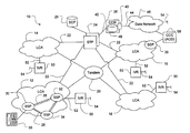
- FIG. 1 is a schematic diagram of a portion of a Public Switched Telephone Network (PSTN) configured in accordance with the invention
- FIGS. 2 a and 2 b are call progress diagrams showing principal steps involved in respective call treatments of a call when resources are, and are not, available at a service provider's facilities, in accordance with one embodiment of the invention
- FIG. 3 is a call progress diagram showing principal steps involved in the call treatment and discrimination of a toll-free call that is forwarded directly to the toll call termination equipment, and subsequently parked at a local service resource until service resources become available;
- FIG. 4 is a call progress diagram showing principal steps involved in the call treatment and service discrimination of a call when resources are available at a service provider's facilities, in accordance with another embodiment of the invention
- FIG. 5 is a call progress diagram showing an example of principal steps involved in the call treatment and discrimination of a toll-free call when resources are not available, and the caller hangs up after the call is parked;
- FIG. 6 is a call progress diagram showing an example of the principal steps involved in the call treatment and discrimination of a toll-free call when resources are not available, but the caller waits for a connection after the call is parked;
- FIG. 7 is a progress diagram illustrating an example of service discrimination, in accordance with the invention.
- the invention provides a method and apparatus for local call discrimination for calls in a switched telephone network.
- calls placed to selected directory numbers are routed to enhanced Integrated Services Digital Network-User Part (ISUP) voice-grade trunks so that associated call control messages are routed to a call control node, which is a virtual switching point in the switched telephone network.
- ISUP Integrated Services Digital Network-User Part
- the call control node queries service termination equipment to determine whether service termination resources are available to handle the call. If so, the call is forwarded through the network to the service termination equipment. If not, the call is parked at a local service resource until service termination resources become available.
- calls to the selected directory numbers are initially passed straight through the call control node to the service termination equipment.
- Service discrimination is performed at the service termination equipment and if service termination resources are not available to serve the call, a data message is sent to the call control node to request that the call be released and parked at a service resource that is local to the calling party.
- the call control node assumes control of the selected calls and routes the calls to a selected local service resource, such as an Interactive Voice Response Unit (IVR), which is programmed to interact with the calling party to discriminate a type/level of service required for the call.
- a selected local service resource such as an Interactive Voice Response Unit (IVR)
- IVR Interactive Voice Response Unit
- the local service resource has obtained and analyzed information from the caller needed for discrimination, the availability of resources at the service termination equipment deemed to be appropriate to the calling party, is determined.
- the IVR may determine the availability of resources in different ways, depending on particular instantiations of the invention.
- the IVR may exchange messages over a data network with the service termination resource (or an automated call distributor that represents one or more such service termination resources) directly; the IVR may simply send the type/level of service information over the data network to the service termination resource (or automated call distributor), and await a response that indicates both availability and routing information pertaining to the call; or the IVR may exchange signaling with the call control node that performs the availability determination. It is also possible that the IVR-type resource is not aware of the status of resources and simply provides generic information based on the number presented to the resource on initial routing.
- the call control node and/or the local service resource initiates a signaling sequence to release the call from the IVR and complete the call to the service termination equipment. If resources are not available at the service termination equipment, the IVR is informed and requested to play a call park announcement.
- the call park announcement may be included in a message that requests the message to be played, it may be a generic message played independently of the called number and call discrimination, or the IVR may be able to determine a selection to play in response to a redirect number inserted into the call establishment message used to connect the caller to the IVR, for example.
- the call control node and/or IVR releases the call connection between the IVR and the call control node, and initiates a signaling sequence to re-complete the call to the available resource.
- FIG. 1 is a schematic diagram of a portion of a Public Switched Telephone Network (PSTN) 10 configured in accordance with the invention.
- PSTN Public Switched Telephone Network
- the PSTN 10 is organized in a plurality of Local Calling Areas (LCAs) 12 , 14 , 16 and 18 which are, in turn, connected to a plurality of tandem switches 20 , only one of which is shown for the sake of simplicity.
- LCA Local Calling Areas
- SSPs Service Switching Points
- Each SSP has a line side to which subscriber local loops are connected and a trunk side to which other SSPs are connected in a manner well known in the art.
- a call control signaling network typically a Signaling System 7 (SS7) packet network which includes signaling links 22 to Signal Transfer Points (STPs) 24 (only one redundantly paired STP 24 illustrated).
- STPs Signal Transfer Points
- Required signaling links between to each SSP and the STP 24 have not been shown for simplicity of illustration.
- the PSTN 10 is preferably an Enhanced Application Network (EAN) described in Applicant's co-pending United States patent application referred to above.
- EAN Enhanced Application Network
- EISUP Voice-grade
- the apparatus in accordance with the invention further includes a Call Control Node (CCN) 38 , which is connected by a signaling link 42 to the STP 24 .
- the CCN 38 also supports a data interface 40 (via a network connection 44 ) to the data network 46 .
- the CCN 38 includes a memory 48 for storing information about each call in progress, including a status of each call, and preferably also information about service resources and their respective availabilities.
- the apparatus in accordance with the invention further includes a plurality of IVRs 50 , which are preferably distributed across the PSTN 10 so that each LCA includes at least one IVR 50 to serve as local service resources in accordance with the present invention.
- the IVRs 50 are connected to respective SSPs of respective LCAs by respective trunks such as Integrated Service Digital Network (ISDN) Private Rate Interface (PRI) 52 or a Small Message Desk Interface (SMDI) 52 , in a manner well known in the art.
- ISDN Integrated Service Digital Network
- PRI Private Rate Interface
- SMDI Small Message Desk Interface
- Each IVR 50 also supports a data interface to which a data link 54 is connected for providing the IVR with access to the data network 46 .
- a call center controller (CCC) 58 is also connected to the data network 46 , and adapted to exchange messaging with at least one of the CCN 38 or the IVRs 50 , whichever is responsible for initiating call prompting with announcements or call re-connection in accordance with the present invention.
- the CCN 38 is responsible for initiating call re-connection.
- either one of the CCN 38 and IVR 50 may bear this onus.
- the CCC 58 may be associated with any number of service termination equipment (call centers, voice servers, etc.), of one or more locations, departments, services, or even companies, and consequently may handle multiple queues for respective calls awaiting respective categories of services.
- the CCC 58 comprises an interface with the PSTN 10 that enables it to receive calls, and perform call discrimination. This is preferably performed with automated equipment that is not necessarily equipped to provide subsequent service for the call, but rather serves as a centralized reception for the callers to the called number.
- the CCC 58 may be further adapted to receive caller supplied information used for call discrimination, and perform call discrimination prior to determining availability of resources for respective calls.
- FIG. 2 a is a call progress diagram showing the principal steps involved in the call treatment of a call initiated from telephone 56 , in accordance with a first embodiment of the invention.
- a caller using telephone 56 takes the telephone off-hook (step 59 ) to place a 1-800 call.
- the SSP 30 detects the off-hook condition, it applies a dial tone (step 60 ) to the calling party's subscriber line.
- the caller dials a 1-800 number (step 61 ).
- Translation tables in the SSP 30 identify the dialed number as a 1-800number and instruct the SSP 30 to send a Transaction Capabilities Application Part (TCAP) query message (step 62 ) to ISCP 26 .
- TCAP Transaction Capabilities Application Part
- the query message contains the 1-800 number and Calling Line Identification (CLID) or Automatic Number Identification (ANI) information.
- the ISCP 26 translates the 1-800 number, and returns routing information to the SSP 30 (step 63 ) that includes, for example, a Carrier Identification Code (CIC) used to force the call to an EISUP trunk in the LCA 12 (FIG. 1 ).
- CIC Carrier Identification Code
- the SSP 30 routes the call onto the EISUP trunk 28 ( FIG. 1 ) by formulating an ISUP-Initial Address Message (IAM), and sending the IAM over the call control signaling network to the CCN 38 (step 64 ).
- IAM ISUP-Initial Address Message
- the CCN 38 receives the IAM, extracts the dialed 1-800 number and Calling Line Identification (CLID), or Automatic Number Identification (ANI) from the IAM, and launches a query to the ISCP 26 to obtain routing information for the call (step 65 ).
- the ISCP 26 translates the number and returns (in step 66 ) a directory number (123-4567 in this example) that can be used to complete the call to service termination equipment (CCC 58 , FIG. 1 ).
- the ISCP 26 is adapted to provide different TCAP responses to substantially the same TCAP query messages, in dependence upon an origin of the message. In this way the directory number is returned to the CCN 38 , and the CIC is returned to the SSP 30 , as in step 63 .
- the CCN 38 then records information about the call and its progress in a call progress table that is maintained in the memory 48 .
- Table 1 illustrates one example of a call progress table:
- Each row in the call progress table is associated with one call and includes, for example, fields for recording a Calling Number, (the Calling Line Identification (CLID) or Automatic Number Identification (ANI) information normally available in IAMs); a unique Serial Number generated in any known way by the CCN 38 to permit tracking/referencing of the call, especially if the CLID or ANI information is unavailable or not unique, the Unique trunk ID, which includes the Destination Point Codes and CIC number; and, information about a status of the call. Flags are used to simplify the tracking of a status of the call (e.g. Service Discrimination, Call Park and Call Center Connection). This particular example illustrates that the call has just been routed to the EISUP trunk 28 and has not yet been forwarded to a service resource for service discrimination. A value of “0” indicates that the status of the call has not passed through the service discrimination, call park or service center stages.
- the CCN 38 then formulates a query message and sends the query message through the data network 46 ( FIG. 1 ) to the CCC 58 that (in the present embodiment) serves independent queues for a plurality of service termination equipment associated with the 1-800 number (step 67 ).
- the CCC 58 replies to the query (step 68 ) indicating that resources are available to handle the call. Consequently, the CCN 38 formulates an IAM which it forwards (step 69 ) through the network to the SSP 32 .
- the SSP 32 forwards the IAM into the PSTN 10 (step 70 ) where it is forwarded hop-by-hop through the network in a manner well known in the art, until the call is extended to the service termination equipment serving directory number 123-4567.
- the resource available message from the CCC 58 includes a directory number (other than 123-4567) to which the call is to be terminated.
- the second query to the SCP is not required because the call center software provides that information.
- an Address Complete Message is returned to the SSP 32 (step 71 ), which automatically relays the ACM to the CCN 38 (step 72 ).
- the CCN 38 subsequently forwards the ACM to the SSP 30 (step 73 ) and the call connection is completed across the network.
- an Answer message (ANM) is transferred back through the signaling network in steps 74 - 76 , following the same path.
- the call setup is now complete and active (step 77 ), and conversation can begin between the calling party at telephone 56 and an agent (or automated system) (not shown) connected by the CCC 58 .
- FIG. 2 b is a call progress diagram showing the principal steps involved in the call treatment of a call initiated from telephone 56 in accordance with the first embodiment of the invention, when a service termination resource is not available to serve the call.
- Steps 59 to 67 of FIG. 2 a are identical with corresponding steps 59 b to 67 b of FIG. 2 b , and their descriptions will not be repeated here.
- the response to the resource available query of step 67 b indicates that no resources are available to handle the call ( 68 b ).
- the CCN 38 selects a nearest available local service resource at which the call can be parked until service termination resources become available to handle the call.
- the CCN 38 uses, for example, an exchange code extracted from CLID or ANI as an index in a look-up table to identify the closest available service resource to the calling party (IVR 50 , in this example).
- Table 2 illustrates an exemplary look-up table for determining the nearest service resource with the exchange code and occupancy of local IVRs:
- the local calling area is first determined using a look-up table (not shown) that associates an originating point code (OPC) of the IAM with the LCA 12 , which is identified by any suitable code.
- OPC originating point code
- the LCA 12 and the exchange code, extracted from CLID/ANI information in the IAM, are then used in Table 2 to determine the local service resource (IVR, music termination of a switch, etc.) to which the call should be routed. If the nearest service resource identified in Table 2 has no capacity to accept the call, another IVR (preferably also in LCA 12 ) is selected.
- the occupancy information indicates the number of calls currently being handled by each IVR and a delta with the Total IVR capacity can be calculated identifying current availability.
- the IVRs in the local call area #1 are currently handling 15 and 2 calls, respectively.
- the CCN 38 can use the current occupancy information of a respective service resource to determine current availability of the respective service resources.
- an IVR 50 local to the calling party is selected.
- the CCN 38 formulates an IAM, which it forwards to the SSP 32 (step 74 b ).
- the SSP 32 is prompted by the received IAM to formulate an ISDN-Setup message, which it relays to the IVR 50 (step 75 b ).
- the IVR 50 returns an ISDN Alert message (step 76 b ), which prompts the SSP 32 to formulate an ACM that it returns to the CCN 38 (step 77 b ).
- the CCN 38 relays the ACM to the SSP 30 (step 78 b ), a call path between IVR 50 and the calling party 56 has been established and the calling party 50 hears ringing.
- the IVR 50 When the IVR 50 answers the call, it returns an ISDN Connect message to the SSP 32 (step 79 b ), which returns an Answer message (ANM) to the CCN 38 (step 80 b ). The CCN 38 , in turn, forwards the ANM to the SSP 30 (step 81 b ). Meanwhile, the SSP 32 returns an ISDN Acknowledge message (ACK) to the IVR 50 (step 82 b ), completing the setup of the call. The IVR (step 83 b ) plays appropriate content to the caller at telephone 56 .
- the appropriate content is generic content used for all callers parked at the local service resource.
- the directory number used to terminate the call at the IVR 50 is used to determine which content is appropriate to the call.
- the content delivered to parked callers can also be tailored to the service subscriber to which the call is placed by sending the message to be played to the caller from the Call Center Controller 58 , or otherwise indicating which message is appropriate in a call park message.
- the CCC 58 sends a data message through the data network 46 to the CCN 38 (step 84 b ) to inform the CCN 38 that the parked call can now be completed.
- the message contains enough information to permit the CCN 38 to identify the parked call using Table 1, as described above.
- the CCC 58 may simply indicate a number of calls from an existing queue that can now be completed, if the CCN 38 is adapted to maintain the queues for the parked calls.
- the CCN 38 responds to the data message by releasing the call segment to the IVR 50 .
- the CCN 38 begins the release sequence by formulating a REL message, which it forwards to the SSP 32 (step 85 b ).
- the SSP 32 returns a RLC message, in step 87 b .
- the SSP 32 completes the release of the call by sending an ISDN-Disconnect message (step 89 b ) to the IVR 50 .
- the IVR 50 returns an ISDN-RLC (step 90 b ), which indicates that the connection to the IVR 50 is released.
- Steps 85 b - 88 b outline one way that a call connection between the CCN 38 and IVR 50 can be released without tearing down the remainder of the call connection, but it is not the only way.
- the call can equally be released by setting the line of the IVR 50 of-hook, as long as the CCN 38 has been directed to discard a REL message associated with the call once it arrives at the CCN 38 .
- U.S. Pat. No. 6,075,855 which issued to Christiansen on Jun. 13, 2000, and is incorporated herein by reference, teaches such a method of reconnection of a call in progress.
- the CCN 38 formulates an IAM, which it forwards to the SSP 32 (step 91 b ).
- the SSP 32 forwards the IAM through the PSTN 10 (step 92 b ), which is advanced to the SSP 36 (of FIG. 1 ) that serves the call center 58 , as explained above.
- An ACM is returned to SSP 32 (step 93 b ) and is forwarded (step 94 b ) to the CCN 38 .
- the CCN 38 discards the ACM (step 95 b ) to avoid an error at the SSP 30 , which deems the call active on the EISUP trunk and is not expecting a call completion message.
- An ANM is also returned to the SSP 32 (step 96 b ) after the call center 58 answers the call.
- the SSP 32 forwards the ANM to the CCN 38 (step 97 b ), and the CCN 38 discards it (step 98 b ) for the reason stated above.
- the call connection to the call center 58 is now complete, and conversation between the caller and a call center agent or automated attendant (not shown) ensues (step 99 b ).
- FIG. 3 is a call progress diagram showing the principal steps involved in the call treatment and discrimination in accordance with the second embodiment of the invention.
- all calls are passed straight through to the call center 58 for call discrimination.
- a call park request is sent from the call center 58 to the CCN 38 , which releases the call from the call center 58 , and parks the call at a an optimum service resource, pending availability of service termination resources to handle the call.
- steps 59 c to 66 c are identical with respective steps of 59 to 66 and 59 b to 66 b , and descriptions of these will not be repeated here.
- step 67 c the CCN 38 formulates an IAM which it forwards (step 67 c ) through the network to the SSP 32 , the IAM being addressed to the call center 58 that is adapted to perform the call discrimination.
- the SSP 32 relays the IAM into the switched telephone network (step 68 c ) where it is forwarded hop-by-hop through the network, in a manner well known in the art, until the call is extended to the call center 58 .
- an Address Complete (ACM) message is returned hop-by-hop to the SSP 32 (step 69 c ), which relays the ACM to the CCN 38 (step 70 c ).
- the CCN 38 relays the ACM to the SSP 30 (step 71 c ) and the call connection is completed across the network.
- an Answer message (ANM) is transferred hop-by-hop back through the call control signaling network in steps 72 c - 74 c , following the same path.
- ACM Address Complete
- the call center 58 may connect the caller to a service node that plays a menu of options to the caller to determine how the call should be terminated (not shown). In this example, no suitable service termination resource is available to handle the call, and the call center 58 sends a call park request through the data network 46 to the CCN 38 (step 75 c ).
- the CCN On receipt of the call park request, the CCN releases the call from the call center 58 by formulating a REL message that it forwards in step 76 c to the SSP 32 .
- the SSP 32 responds with a RLC message (step 77 c ) and formulates a REL message that it forwards through the switched telephone network (step 78 c ) to complete the release of the call.
- a RLC is returned to the SSP 32 (step 79 c ) and the release of the connection is completed in a manner well understood in the art.
- the CCN 38 consults its Table 2, for example, to locate a local service resource where the call can be parked (step 80 c ), and forwards a call park message to the selected IVR 50 , advising the IVR 50 of a call that will be parked there, and indicating which message to play to the calling party (also in step 80 c ).
- the CCN 38 formulates an IAM and sends it (in step 81 c ) to the SSP 32 to connect the caller to the local service resource (IVR 50 in this example).
- the SSP 32 responds by sending an ISDN-Setup message to the IVR 50 (step 82 c ).
- the IVR 50 returns an ISDN-Alert message in step 83 c , which causes the SSP 32 to return an ACM (step 84 c ) to the CCN 38 .
- the CCN 38 discards it (step 85 c ) for reasons detailed above.
- the IVR 50 answers the call and sends an ISDN-Connect (step 86 c ) to the SSP 32 , which subsequently returns an ANM (step 87 c ) to the CCN 38 .
- the CCN 38 likewise discards the ANM, in step 88 c . Call setup is completed when the SSP 32 sends an ISDN-Acknowledge message to the IVR 50 in step 89 c.
- call park content is played to the calling party (step 90 c ) until service termination resources become availability.
- the call center 58 sends a data message to the CCN 38 (step 91 c ), which triggers a release and reconnect sequence as described above in steps 85 b - 99 b with reference to FIG. 2 b.
- FIG. 4 is a call progress diagram showing the principal steps involved in the call treatment and discrimination of a toll-free call initiated from telephone 56 , in accordance with the third embodiment of the invention. Steps leading to the CCN 38 receiving a directory number from the ISCP 26 in step 112 , remain the same as corresponding steps of FIGS. 2 a - 3 , and will not be repeated herein.
- a nearest service resource with free capacity is selected by the CCN 38 , and an IAM is forwarded to the selected service resource (IVR 50 ).
- the routing number in the received IAM is replaced with the directory number of the selected service resource and forwarded to the SSP 32 (step 116 ).
- the SSP 32 forwards an ISDN-setup message (step 118 ) over a PRI channel of an ISDN trunk 52 to the IVR 50 .
- the IVR 50 responds to the Setup message by returning an Alert message (step 120 ) to the SSP 32 .
- the SSP 32 On receipt of the Alert message (step 120 ), the SSP 32 sends an Address Complete (ACM) message (step 122 ) to the CCN 38 , which relays the received ACM to the SSP 30 (step 124 ). Meanwhile, the IVR 50 forwards a Connect message (step 126 ) to the SSP 32 to signal that it has answered the call. The SSP 32 responds by formulating an ANM message (step 128 ) addressed to the CCN 38 . The CCN 38 forwards the ANM message (step 132 ) to the SSP 30 . Meanwhile, the SSP 32 acknowledges the Connect message (step 126 ) from the IVR 50 by returning an ISDN acknowledge (ACK) message (step 130 ) to the IVR 50 .
- ACM Address Complete
- ACK ISDN acknowledge
- the CCN 38 forwards Service Information through the data network 46 ( FIG. 1 ) to the IVR 50 , to provide the IVR with information about the service subscriber (1-800 number), for example. Alternatively, the service subscriber information can be passed in a Redirect Number field of the IAM, or the like.
- the IVR 50 uses the service subscriber information to select content to be presented to the calling party 56 and interacts (step 136 ) with the calling party 56 to discriminate a type and/or level of service required for the call. After the IVR 50 has obtained the required information from the caller, as will be explained below with reference to FIG.
- the IVR 50 passes the routing information (step 138 ) back through the data network to the CCN 38 .
- the CCN 38 uses the routing information to determine the availability of resources at the call termination selected by the caller's interaction with the IVR 50 (step 140 ).
- the CCN 38 determines the availability of resources at the call termination, which may be a call center, using a call center availability table (Table 3). Table 3 is stored and maintained in the memory 48 of the CCN 38 .
- Table 3 An example of a call center availability table is shown below:
- Table 3 includes a “Directory Number” and a variable number of flags associated with respective extensions, e.g. “Ext. 1”, “Ext. 2, . . . “Ext. N”.
- the directory number is used to access the call center.
- the extension flags are used to track the availability of extensions used to field calls to the call center. If an extension field is set to any value other than 0 or 1, “*”, for example, as shown for Ext. 2 in Table 3, there is no agent at the extension, or the extension is unavailable for some other reason. Such extensions are ignored in determining capacity at the call center.
- the status of extensions stored in Table 3 is maintained by an administrator at the respective call centers using a remote maintenance interface of a type well known in the art. This information can also be obtained through an availability query to the call center control node 58 that represents the call center, through data network 46 . If all calls to the call center are not relayed through the CCN 38 , this alternative manner of obtaining the information may be required.
- the IVR 50 is adapted to interface with the call center control node 56 to determine availability of resources at a suitable service termination to handle the call.
- the IVR 50 sends a message to the CCN 38 , directing the CCN 38 to release and reconnect the specific call to the available resource. This relieves some processing and messaging demand on the CCN 38 .
- the CCN 38 therefore formulates a release message (REL) (step 142 ), which is forwarded to the SSP 32 .
- REL release message
- the SSP 32 formulates an ISDN-Disconnect message (step 144 ), which it forwards to the IVR 50 .
- the IVR 50 returns an ISDN-Release Complete (RLC) message (step 146 ) to the SSP 32 , thus releasing all resources associated with the call placed to the IVR 50 .
- RLC ISDN-Release Complete
- SSP 32 has formulated an RLC message that is sent (step 148 ) to the CCN 38 .
- the CCN 38 then formulates an IAM message (step 152 ) using the routing information that was received from the IVR 50 in the step 138 .
- the IAM message is forwarded (step 154 ) through the switched telephone network to an SSP that serves the call center, using standard call routing techniques.
- the SSP formulates an ACM, which is returned through the network to the CCN 38 (step 156 ).
- the CCN 38 discards it (step 158 ).
- the SSP formulates an ANM message that is forwarded (step 160 ) to the CCN 38 .
- the CCN 38 discards the ANM message (step 162 ).
- the CCN 38 then, in step 164 , updates the resource availability table (Table 3) as the conversation begins (step 168 ) between the caller and call center. After the conversation is completed, for example, the agent handling the call at the call center goes on-hook. The on-hook condition is detected at the SSP serving the call center (not shown). In response, the SSP formulates and issues a REL message, which is propagated through the PSTN 10 to the CCN 38 (step 170 ). When the CCN 38 receives the REL message, it returns a RLC message (step 174 ) and relays the REL message to the SSP 30 (step 172 ), which returns an RLC (step 176 ).
- Table 3 resource availability table
- step 180 the SSP 30 applies a disconnect tone (step 180 ) to the telephone 56 line, which prompts the caller to return the telephone 56 on-hook (step 182 ).
- step 178 the resource availability table (Table 3) is revised in light of the availability of the call center.
- FIG. 5 is a call progress diagram showing an example of the principal steps involved in the call treatment and discrimination of a toll-free call initiated from telephone 56 when the resources are not available at a dialed call center, and the calling party decides not to hold.
- Steps 202 - 240 leading to service discrimination and a determination of availability of the resources to handle the type and level discriminated for the call remain the same as corresponding steps 102 - 140 of FIG. 4 , and will not be repeated herein.
- the CCN 38 determines that no suitable resource is available at the selected call termination(s) to handle the call. Consequently the CCN 38 issues a call park message (step 242 ) through data network 46 to the IVR 50 .
- the IVR 50 responds to the call park request by playing a recorded call park message.
- the recorded call park message is associated with at least the 1-800 number, if not also with the call discrimination (step 244 ).
- the call park information duplicates what the caller would hear if on hold at the service subscriber's call termination equipment. It is assumed in the present case that the caller decides to end the call rather than wait. Consequently, the caller's telephone 56 is placed on-hook (step 248 ).
- the SSP 30 On receipt of the on-hook signal, the SSP 30 formulates a REL message (step 250 ), which is forwarded to the CCN 38 , and the CCN 38 relays the REL message to the SSP 32 (step 252 ).
- the SSP 32 On receipt of the REL message (step 252 ), the SSP 32 formulates an ISDN-REL message, which it forwards to the IVR 50 (step 246 ). Meanwhile, the CCN 38 and the SSP 32 have returned RLC messages (steps 256 and 258 , respectively).
- the IVR 50 releases the call, and returns an ISDN Disconnect message (step 254 ) to the SSP 32 .
- the CCN 38 also updates resource availability (step 260 ) to indicate that the IVR 50 is serving one less caller.
- FIG. 6 is a call progress diagram showing an example of the principal steps involved in the call treatment and discrimination of a toll-free call initiated from telephone 56 when the resources at the call center are not available, but the caller decides to hold until the resources at the call center become available.
- Steps 302 344 are the same as corresponding steps 202 - 244 of FIG. 5 , and will not be repeated here.
- the CCN 38 periodically checks the availability of resources by monitoring Table 3, until resources become available to handle the call. If a plurality of callers is on hold for the same service provider or class of service, the CCN 38 preferably selects the caller that has been on hold longest within each customer category, each time a resource at the service subscriber becomes available to handle a call. Consequently, a time stamp is preferably associated with each parked call to ensure that the CCN 38 is enabled to select the correct one of a plurality of parked calls. Of course in other embodiments the queue may be managed by a Call Center Control Node 58 .
- the CCN 38 then formulates a REL message (step 346 ), and forwards it to the SSP 32 , to release the calling party 56 from the IVR 50 .
- the SSP 32 formulates an ISDN-Disconnect message (step 348 ), which it forwards to the IVR 50 .
- the IVR 50 returns an ISDN-RLC message (step 350 ) to the SSP 32 , thus releasing all resources associated with the call placed to the IVR 50 . Meanwhile, the SSP 32 formulates a RLC message that it forwards (step 352 ) to the CCN 38 .
- the CCN 38 formulates an IAM message (step 356 ) containing the routing information received in the routing information message (step 338 ).
- the IAM is forwarded (step 358 ) through the PSTN 10 toward an SSP that serves the available resource.
- the SSP subsequently formulates an ACM that is propagated through the network to the CCN 38 (step 360 ).
- the CCN 38 discards the ACM (step 362 ).
- the SSP formulates an ANM indicating that the line is answered at the call center.
- the ANM is likewise propagated through the PSTN 10 along the switches of the call connection until it is forwarded (in step 364 ) to the CCN 38 .
- the CCN 38 likewise discards the ANM (step 366 ) and updates the resource availability table associated with the selected service termination resource (step 368 ).
- the connection between the caller's telephone 56 and the selected service termination resource is completed, (step 370 ) and conversation ensues between the caller and a call center agent (not shown). After the conversation is completed, the connection is released in steps 372 - 384 , which are substantially the same as steps 170 - 182 as described above.
- FIG. 7 is a schematic process flow diagram illustrating an example of service discrimination.
- a caller using telephone 56 interacts with IVR 50 .
- the IVR provides complete routing information to the CCN 38 , which completes a call connection between the caller and a toll-free service provider call facility, such as a call center or an enterprise IVR 50 .
- the IVR 50 receives service information that comprises (if available) CLID or ANI and preferably also a number that was dialed by the caller using telephone 56 (either in a redirecting number field of the IAM used to initiate the call completion, or in a data message from the CCN 36 ).
- the IVR 50 sends a service information query message (step 402 ) to the ISCP 26 .
- the ISCP 26 translates (step 404 ) the information received, and returns an identifier of a service discrimination profile to the IVR 50 (step 406 ).
- the service discrimination profile is used to tailor the service discrimination to the requirements of the service provider to which the call is directed.
- the service discrimination profile identifier provides a number used as an index to retrieve a pre-recorded menu of options that are played to the caller in a manner well known in the art.
- any enterprise database may be substituted for the ISCP 26 in this particular role.
- the IVR 50 On receipt of the service discrimination profile identifier, the IVR 50 retrieves the appropriate service profile and plays (step 408 ) an associated pre-recorded message to the caller.
- the caller using a keypad of the telephone 56 , responds to the pre-recorded message by selecting an option (step 410 ) and generating (in step 412 ) Dual Tone Multi-Frequency (DTMF) signals.
- DTMF signals are converted into digital information and translated (step 414 ) by the IVR 50 into service discrimination information.
- any number of iterations of steps 408 to 412 using different messages to prompt the caller for still more service discrimination options may be used.
- the IVR 50 sends the service discrimination information (step 416 ) to the ISCP 26 .
- the ISCP 26 translates it into routing information (step 418 ) and returns (step 420 ) the routing information to the IVR 50 .
- the invention therefore provides a method and system for providing local call treatment that permits calls to be parked in the caller's local calling area (or a nearest LCA) pending availability of service termination resources, and optionally perform service discrimination that permits service availability to be determined before calls are extended across the network.
- Parked calls therefore only tie up switch resources close to the caller freeing up network and enterprise capacity that would otherwise be consumed.
- Call distributions are handled more efficiently and single-number calling to a plurality of distributed call centers or call agents is enabled.
- the invention lessens need for installation and maintenance of call handling equipment at call centers and enterprise IVRs, as calls are not parked there. Since the call center only handles calls for which call agents are available, fewer Public Branch Exchange or Call center controller circuits are required. Savings are therefore realized in the network as well as at each call center served by the apparatus, in accordance with the invention.
- service nodes such as IVR 50 can be connected to the switched telephone network using a Small Message Desk Interface (SMDI), rather than an ISDN trunk.
- SMSI Small Message Desk Interface
- Another example would be providing identical functionality in a mobility network or between a mobility network and the PSTN.
Abstract
Description
| TABLE 1 | ||||||
| Routing | Service | Call | ||||
| Calling | Serial | Trunk | Infor- | Discrimi- | Call | Center |
| Number | Number | ID | mation | nation | Park | Connection |
| CLID or | Unique | PC | Number | 0 | 0 | 0 |
| ANI | Number | CIC | ||||
| TABLE 2 |
| Table of Local Service Resources |
| Local | ||||
| Calling | Exchange | IVR | IVR | Directory |
| Area | Code | Capacity | Occupancy | No. |
| #1 | 101, 402, | 30 | 15 | |
| 172, 166, | ||||
| 237 | ||||
| #1 | 222, 310, | 20 | 2 | |
| 311, 410, | ||||
| 611, 567 | ||||
| #2 | 146, 216 | 20 | 0 | |
| 226, 228, | ||||
| 229, 231, | ||||
| 236 | ||||
| #2 | 341, 347, | 50 | 4 | |
| 382, 396, | ||||
| 397, 404 | ||||
| TABLE 3 |
| Directory Number |
| Ext. 1 | Ext. 2 | . . . | Ext. N | ||
| 0 | * | . . . | 1 | ||
Claims (39)
Priority Applications (3)
| Application Number | Priority Date | Filing Date | Title |
|---|---|---|---|
| US10/198,551 US6839422B2 (en) | 2002-07-18 | 2002-07-18 | Method and apparatus for providing local call treatment discrimination for selected calls on a switched telephone network |
| PCT/CA2003/001087 WO2004010718A1 (en) | 2002-07-18 | 2003-07-18 | Method and apparatus for providing local call treatment discrimination for selected calls in a switched telephone network |
| AU2003249816A AU2003249816A1 (en) | 2002-07-18 | 2003-07-18 | Method and apparatus for providing local call treatment discrimination for selected calls in a switched telephone network |
Applications Claiming Priority (1)
| Application Number | Priority Date | Filing Date | Title |
|---|---|---|---|
| US10/198,551 US6839422B2 (en) | 2002-07-18 | 2002-07-18 | Method and apparatus for providing local call treatment discrimination for selected calls on a switched telephone network |
Publications (2)
| Publication Number | Publication Date |
|---|---|
| US20040013255A1 US20040013255A1 (en) | 2004-01-22 |
| US6839422B2 true US6839422B2 (en) | 2005-01-04 |
Family
ID=30443135
Family Applications (1)
| Application Number | Title | Priority Date | Filing Date |
|---|---|---|---|
| US10/198,551 Expired - Lifetime US6839422B2 (en) | 2002-07-18 | 2002-07-18 | Method and apparatus for providing local call treatment discrimination for selected calls on a switched telephone network |
Country Status (3)
| Country | Link |
|---|---|
| US (1) | US6839422B2 (en) |
| AU (1) | AU2003249816A1 (en) |
| WO (1) | WO2004010718A1 (en) |
Cited By (5)
| Publication number | Priority date | Publication date | Assignee | Title |
|---|---|---|---|---|
| US20060154654A1 (en) * | 2005-01-07 | 2006-07-13 | Cisco Technology, Inc. | Method and system for the automated answering and holding of a call |
| US20070140457A1 (en) * | 2005-12-19 | 2007-06-21 | Sbc Knowledge Ventures Lp | Method and apparatus for selectively routing callers to service call centers |
| US20080043659A1 (en) * | 2006-08-01 | 2008-02-21 | Newstep Networks Inc. | Method and System for Directed Call Establishment to Facilitate the Provision of Enhanced Communications Services |
| US20090003551A1 (en) * | 2007-06-28 | 2009-01-01 | Mitel Networks Corporation | Method And Apparatus For Managing A Call |
| US20110188495A1 (en) * | 2004-12-03 | 2011-08-04 | Marian Croak | Method and apparatus for enabling dual tone multi-frequency signal processing in the core voice over internet protocol network |
Families Citing this family (7)
| Publication number | Priority date | Publication date | Assignee | Title |
|---|---|---|---|---|
| US7636431B2 (en) * | 2004-03-23 | 2009-12-22 | Williams L Lloyd | Method and apparatus for subscriber control of an inbound call |
| US20060165057A1 (en) * | 2004-11-04 | 2006-07-27 | Sbc Knowledge Ventures, L.P. | Presenting dialup access numbers status information using an automated voice response system |
| US8644822B1 (en) | 2006-05-18 | 2014-02-04 | Sprint Spectrum L.P. | Method and system for providing differentiated services to mobile stations |
| US8582750B2 (en) * | 2006-07-31 | 2013-11-12 | Cisco Technology, Inc. | Connection recovery in a call center |
| CN101291293B (en) * | 2008-06-05 | 2011-08-24 | 华为技术有限公司 | Media resource adaptation method, media gateway controller and server |
| US11356555B1 (en) * | 2021-07-30 | 2022-06-07 | Zoom Video Communications, Inc. | Message-based interactive voice response menu reconnection |
| US11902470B1 (en) * | 2021-11-19 | 2024-02-13 | 8X8, Inc. | Apparatuses and methods involving parking communications |
Citations (5)
| Publication number | Priority date | Publication date | Assignee | Title |
|---|---|---|---|---|
| US120553A (en) * | 1871-10-31 | Improvement in gun-carriages | ||
| US4191860A (en) | 1978-07-13 | 1980-03-04 | Bell Telephone Laboratories, Incorporated | Data base communication call processing method |
| US5432845A (en) | 1992-12-21 | 1995-07-11 | At&T Corp. | Post answer telephone call redirection or rerouting |
| US5940008A (en) | 1996-07-29 | 1999-08-17 | Northern Telecom Limited | Communications switching network |
| US6493444B2 (en) * | 1999-03-16 | 2002-12-10 | Bell Canada | Enhanced application telephone network |
Family Cites Families (5)
| Publication number | Priority date | Publication date | Assignee | Title |
|---|---|---|---|---|
| AU6143498A (en) * | 1997-02-07 | 1998-08-26 | Mci Communications Corporation | System and method for call park and transfer in a telecommunications network |
| CA2216620C (en) * | 1997-09-24 | 2002-06-25 | Bell Canada | Method and apparatus for dynamically routing calls in an intelligent network |
| GB9802547D0 (en) * | 1998-02-05 | 1998-04-01 | British Telecomm | Call centre |
| EP1001597A3 (en) * | 1998-11-10 | 2003-09-03 | International Business Machines Corporation | Method and system for reducing telephone costs for calls to service providers |
| EP1260088A2 (en) * | 1999-10-29 | 2002-11-27 | Telera, Inc. | Distributed call center with local points of presence |
-
2002
- 2002-07-18 US US10/198,551 patent/US6839422B2/en not_active Expired - Lifetime
-
2003
- 2003-07-18 WO PCT/CA2003/001087 patent/WO2004010718A1/en not_active Application Discontinuation
- 2003-07-18 AU AU2003249816A patent/AU2003249816A1/en not_active Abandoned
Patent Citations (5)
| Publication number | Priority date | Publication date | Assignee | Title |
|---|---|---|---|---|
| US120553A (en) * | 1871-10-31 | Improvement in gun-carriages | ||
| US4191860A (en) | 1978-07-13 | 1980-03-04 | Bell Telephone Laboratories, Incorporated | Data base communication call processing method |
| US5432845A (en) | 1992-12-21 | 1995-07-11 | At&T Corp. | Post answer telephone call redirection or rerouting |
| US5940008A (en) | 1996-07-29 | 1999-08-17 | Northern Telecom Limited | Communications switching network |
| US6493444B2 (en) * | 1999-03-16 | 2002-12-10 | Bell Canada | Enhanced application telephone network |
Cited By (8)
| Publication number | Priority date | Publication date | Assignee | Title |
|---|---|---|---|---|
| US20110188495A1 (en) * | 2004-12-03 | 2011-08-04 | Marian Croak | Method and apparatus for enabling dual tone multi-frequency signal processing in the core voice over internet protocol network |
| US8675638B2 (en) * | 2004-12-03 | 2014-03-18 | At&T Intellectual Property Ii, L.P. | Method and apparatus for enabling dual tone multi-frequency signal processing in the core voice over internet protocol network |
| US20060154654A1 (en) * | 2005-01-07 | 2006-07-13 | Cisco Technology, Inc. | Method and system for the automated answering and holding of a call |
| US20070140457A1 (en) * | 2005-12-19 | 2007-06-21 | Sbc Knowledge Ventures Lp | Method and apparatus for selectively routing callers to service call centers |
| US20080043659A1 (en) * | 2006-08-01 | 2008-02-21 | Newstep Networks Inc. | Method and System for Directed Call Establishment to Facilitate the Provision of Enhanced Communications Services |
| US8787353B2 (en) * | 2006-08-01 | 2014-07-22 | Broadview Networks, Inc. | Method and system for directed call establishment to facilitate the provision of enhanced communications services |
| US20090003551A1 (en) * | 2007-06-28 | 2009-01-01 | Mitel Networks Corporation | Method And Apparatus For Managing A Call |
| US8180026B2 (en) * | 2007-06-28 | 2012-05-15 | Mitel Networks Corporation | Method and apparatus for managing a call |
Also Published As
| Publication number | Publication date |
|---|---|
| US20040013255A1 (en) | 2004-01-22 |
| WO2004010718A1 (en) | 2004-01-29 |
| AU2003249816A1 (en) | 2004-02-09 |
Similar Documents
| Publication | Publication Date | Title |
|---|---|---|
| US8670549B2 (en) | Method and system for improved routing of repair calls to a call center | |
| US7953217B2 (en) | System and method for providing a call back option for callers to a call center | |
| US5590186A (en) | System and method for redirecting a telephone call with call merging | |
| US7020261B2 (en) | Method for providing enhanced directory assistance upon command using out-of-band signaling | |
| US6055305A (en) | Method and apparatus for providing network-based customized call treatment | |
| US7724886B2 (en) | Method and system for providing enhanced caller identification information for subscribers that interface via private trunk groups | |
| US8611513B2 (en) | Methods and telecommunications system for transmitting a facsimile message | |
| US6522743B1 (en) | Routing calls to call centers | |
| US6421437B1 (en) | System and method for re-directing incoming calls | |
| JP3681413B2 (en) | Call transfer or route change after answering | |
| KR100261937B1 (en) | Calling party identification announcement service | |
| KR19990063777A (en) | Method and apparatus for automatic call distribution | |
| JP2002520912A (en) | Method and system for providing network-initiated multilingual operator assistance | |
| US6839422B2 (en) | Method and apparatus for providing local call treatment discrimination for selected calls on a switched telephone network | |
| WO2003075583A1 (en) | Method and system for correlating telephone calls with information delivery | |
| US6885741B1 (en) | System and method for on-hold call back | |
| WO1998053591A1 (en) | Method and apparatus for enhanced call waiting in a telecommunications network | |
| CA2244075C (en) | Intelligent call redirection | |
| JP4259763B2 (en) | Telecommunication network | |
| AU3423999A (en) | Method in a telephone service for implementing queuing according to a desired charge |
Legal Events
| Date | Code | Title | Description |
|---|---|---|---|
| AS | Assignment |
Owner name: BELL CANADA, CANADA Free format text: ASSIGNMENT OF ASSIGNORS INTEREST;ASSIGNORS:WILLIAMS, L. LLOYD;MARKMAN, ALEXANDER;JOHNSTON, DAVID E.;REEL/FRAME:013120/0342 Effective date: 20020710 |
|
| AS | Assignment |
Owner name: REVD NETWORKS, INC., CANADA Free format text: ASSIGNMENT OF ASSIGNORS INTEREST;ASSIGNOR:BELL CANADA;REEL/FRAME:014784/0948 Effective date: 20021220 |
|
| AS | Assignment |
Owner name: NEWSTEP NETWORKS INC., CANADA Free format text: CHANGE OF NAME;ASSIGNOR:REVD NETWORKS, INC.;REEL/FRAME:015355/0594 Effective date: 20031114 |
|
| STCF | Information on status: patent grant |
Free format text: PATENTED CASE |
|
| AS | Assignment |
Owner name: COMERICA BANK, ONTARIO Free format text: SECURITY AGREEMENT;ASSIGNOR:NEWSTEP NETWORKS INC.;REEL/FRAME:019102/0764 Effective date: 20070329 |
|
| FPAY | Fee payment |
Year of fee payment: 4 |
|
| AS | Assignment |
Owner name: NEWSTEP NETWORKS INC., CANADA Free format text: RELEASE BY SECURED PARTY;ASSIGNOR:COMERICA BANK, A TEXAS BANKING ASSOCIATION AND AUTHORIZED FOREIGN BANK UNDER THE BANK ACT, FORMERLY A MICHIGAN BANKING CORPORATION;REEL/FRAME:022708/0751 Effective date: 20090312 |
|
| FEPP | Fee payment procedure |
Free format text: PAYOR NUMBER ASSIGNED (ORIGINAL EVENT CODE: ASPN); ENTITY STATUS OF PATENT OWNER: LARGE ENTITY |
|
| AS | Assignment |
Owner name: BROADVIEW NETWORKS, INC., NEW JERSEY Free format text: ASSET PURCHASE AGREEMENT;ASSIGNOR:NATURAL CONVERGENCE INC.;REEL/FRAME:025549/0272 Effective date: 20090731 Owner name: NATURAL CONVERGENCE INC., CANADA Free format text: ASSET PURCHASE AGREEMENT;ASSIGNOR:4515218 CANADA INC.;REEL/FRAME:025549/0157 Effective date: 20090603 Owner name: 4515218 CANADA INC., CANADA Free format text: ASSET PURCHASE AGREEMENT;ASSIGNOR:NEWSTEP NETWORKS INC.;REEL/FRAME:025549/0095 Effective date: 20090603 |
|
| FPAY | Fee payment |
Year of fee payment: 8 |
|
| AS | Assignment |
Owner name: THE CIT GROUP/BUSINESS CREDIT, INC., IN ITS CAPACI Free format text: PATENT SECURITY AGREEMENT;ASSIGNOR:BROADVIEW NETWORKS, INC.;REEL/FRAME:028885/0034 Effective date: 20120823 |
|
| AS | Assignment |
Owner name: CIT FINANCE LLC, AS ADMINISTRATIVE AGENT FOR THE S Free format text: PATENT SECURITY AGREEMENT;ASSIGNOR:BROADVIEW NETWORKS, INC.;REEL/FRAME:029309/0006 Effective date: 20121113 Owner name: BROADVIEW NETWORKS, INC., NEW YORK Free format text: TERMINATION AND RELEASE OF PATENT SECURITY AGREEMENT;ASSIGNOR:THE CIT GROUP/BUSINESS CREDIT, INC., IN ITS CAPACITY AS ADMINISTRATIVE AGENT FOR THE SECURED PARTIES;REEL/FRAME:029301/0692 Effective date: 20121113 |
|
| FPAY | Fee payment |
Year of fee payment: 12 |
|
| AS | Assignment |
Owner name: WINDSTREAM INTELLECTUAL PROPERTY SERVICES, LLC, ARKANSAS Free format text: ASSIGNMENT OF ASSIGNORS INTEREST;ASSIGNOR:BROADVIEW NETWORKS, INC.;REEL/FRAME:056510/0260 Effective date: 20210611 |
|
| AS | Assignment |
Owner name: JPMORGAN CHASE BANK, N.A., AS COLLATERAL AGENT, NEW YORK Free format text: SECURITY INTEREST;ASSIGNOR:WINDSTREAM INTELLECTUAL PROPERTY SERVICES, LLC;REEL/FRAME:057526/0925 Effective date: 20210826 |