US6844553B2 - Absorption spectroscopy apparatus and method - Google Patents
Absorption spectroscopy apparatus and method Download PDFInfo
- Publication number
- US6844553B2 US6844553B2 US10/081,655 US8165502A US6844553B2 US 6844553 B2 US6844553 B2 US 6844553B2 US 8165502 A US8165502 A US 8165502A US 6844553 B2 US6844553 B2 US 6844553B2
- Authority
- US
- United States
- Prior art keywords
- cell
- source
- detector
- side wall
- absorption spectroscopy
- Prior art date
- Legal status (The legal status is an assumption and is not a legal conclusion. Google has not performed a legal analysis and makes no representation as to the accuracy of the status listed.)
- Expired - Fee Related
Links
- 238000004847 absorption spectroscopy Methods 0.000 title claims abstract description 43
- 238000000034 method Methods 0.000 title description 7
- 239000012530 fluid Substances 0.000 claims abstract description 19
- 238000010521 absorption reaction Methods 0.000 description 12
- 239000007789 gas Substances 0.000 description 9
- 238000004611 spectroscopical analysis Methods 0.000 description 8
- 238000004458 analytical method Methods 0.000 description 6
- 238000004519 manufacturing process Methods 0.000 description 5
- 239000007788 liquid Substances 0.000 description 4
- 230000035945 sensitivity Effects 0.000 description 4
- 239000000126 substance Substances 0.000 description 4
- 239000000463 material Substances 0.000 description 3
- 239000000203 mixture Substances 0.000 description 3
- 238000002310 reflectometry Methods 0.000 description 3
- 239000010410 layer Substances 0.000 description 2
- 229910052751 metal Inorganic materials 0.000 description 2
- 239000002184 metal Substances 0.000 description 2
- 238000012986 modification Methods 0.000 description 2
- 230000004048 modification Effects 0.000 description 2
- 230000003287 optical effect Effects 0.000 description 2
- UGFAIRIUMAVXCW-UHFFFAOYSA-N Carbon monoxide Chemical compound [O+]#[C-] UGFAIRIUMAVXCW-UHFFFAOYSA-N 0.000 description 1
- 230000002411 adverse Effects 0.000 description 1
- 229910002091 carbon monoxide Inorganic materials 0.000 description 1
- 239000011248 coating agent Substances 0.000 description 1
- 239000011247 coating layer Substances 0.000 description 1
- 238000000576 coating method Methods 0.000 description 1
- 230000000694 effects Effects 0.000 description 1
- PCHJSUWPFVWCPO-UHFFFAOYSA-N gold Chemical compound [Au] PCHJSUWPFVWCPO-UHFFFAOYSA-N 0.000 description 1
- 239000010931 gold Substances 0.000 description 1
- 229910052737 gold Inorganic materials 0.000 description 1
- 238000005259 measurement Methods 0.000 description 1
- 238000012544 monitoring process Methods 0.000 description 1
- 230000005855 radiation Effects 0.000 description 1
- 239000007787 solid Substances 0.000 description 1
Images


Classifications
-
- G—PHYSICS
- G01—MEASURING; TESTING
- G01N—INVESTIGATING OR ANALYSING MATERIALS BY DETERMINING THEIR CHEMICAL OR PHYSICAL PROPERTIES
- G01N21/00—Investigating or analysing materials by the use of optical means, i.e. using sub-millimetre waves, infrared, visible or ultraviolet light
- G01N21/17—Systems in which incident light is modified in accordance with the properties of the material investigated
- G01N21/25—Colour; Spectral properties, i.e. comparison of effect of material on the light at two or more different wavelengths or wavelength bands
- G01N21/31—Investigating relative effect of material at wavelengths characteristic of specific elements or molecules, e.g. atomic absorption spectrometry
-
- G—PHYSICS
- G01—MEASURING; TESTING
- G01N—INVESTIGATING OR ANALYSING MATERIALS BY DETERMINING THEIR CHEMICAL OR PHYSICAL PROPERTIES
- G01N21/00—Investigating or analysing materials by the use of optical means, i.e. using sub-millimetre waves, infrared, visible or ultraviolet light
- G01N21/01—Arrangements or apparatus for facilitating the optical investigation
- G01N21/03—Cuvette constructions
- G01N21/031—Multipass arrangements
-
- G—PHYSICS
- G01—MEASURING; TESTING
- G01N—INVESTIGATING OR ANALYSING MATERIALS BY DETERMINING THEIR CHEMICAL OR PHYSICAL PROPERTIES
- G01N21/00—Investigating or analysing materials by the use of optical means, i.e. using sub-millimetre waves, infrared, visible or ultraviolet light
- G01N21/17—Systems in which incident light is modified in accordance with the properties of the material investigated
- G01N21/25—Colour; Spectral properties, i.e. comparison of effect of material on the light at two or more different wavelengths or wavelength bands
- G01N21/31—Investigating relative effect of material at wavelengths characteristic of specific elements or molecules, e.g. atomic absorption spectrometry
- G01N21/35—Investigating relative effect of material at wavelengths characteristic of specific elements or molecules, e.g. atomic absorption spectrometry using infrared light
- G01N21/3504—Investigating relative effect of material at wavelengths characteristic of specific elements or molecules, e.g. atomic absorption spectrometry using infrared light for analysing gases, e.g. multi-gas analysis
Definitions
- the throughput (etendue) of these cells can be relatively small.
- the small throughput limits the amount of light that can be directed through the sample and limits the sensitivity of the resulting measurement.
- the improved absorption cell that causes light to pass through a very large percentage of a sample contained in the cell.
- the improved absorption cell will prevent the loss of significant amounts of light through ends of the cell and increase the throughput of the cell.
- the improved cell will preferably be compact, robust, and easier to manufacture.
- the improved absorption spectroscopy apparatus of the present invention enables energy to be passed through a very large percentage of a sample within the sample cell.
- the cell is constructed so as to be small and compact while nonetheless enabling the energy to make successive passes through the sample.
- the curved source/detector reflector prevents a decrease in the throughput of the cell.
- the improved apparatus has been found to be robust and easier to manufacture.
- the source/detector reflector comprises a segment of a cylinder.
- the port of the side wall of the cell includes inlet and outlet ports, and the source/detector reflector includes separate source and detector reflectors corresponding respectively to the inlet and the outlet ports.
- the apparatus includes a source for directing energy against the source reflector; and a detector for receiving energy from the detector reflector.
- the apparatus includes an intermediate reflector positioned with respect to the port of the cell and the emitter/detector reflector to reflect energy from the emitter/detector reflector through the port of the cell and against the predetermined location on the reflective surface of the side wall of the cell.
- FIG. 4 is an end plan view of another exemplary embodiment of an improved absorption spectroscopy apparatus constructed in accordance with the present invention.
- FIG. 5 is an end plan view showing a trace of a light ray passing through the absorption spectroscopy apparatus of FIG. 4 ;
- FIG. 6 is a side elevation view of an additional absorption cell constructed in accordance with the present invention.
- FIG. 7 is a sectional view taken along line 7 — 7 of the absorption cell of FIG. 6 ;
- FIG. 8 is a side elevation view of the absorption cell of FIG. 6 , wherein a side panel of the cell is removed and a trace of a light ray is shown directed by a single launch and collection mirror and an intermediate mirror and completing multiple passes through the absorption cell.
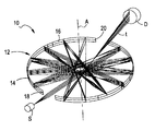
- FIG. 1 of the drawings there is shown a schematic representation of an exemplary embodiment of an improved absorption spectroscopy apparatus 10 constructed in accordance with the present invention.
- the apparatus includes a fluid sample cell 12 having an annular side wall 14 coaxially arranged about an axis “A” of the cell.
- the side wall 14 includes a radially inwardly facing light reflective surface 16 .
- the light reflective surface 16 is preferably polished metal. If a higher reflectivity of the surface 16 is desirable, the surface can be coated with one or more layers of a reflective material such as gold, other metallic layers or a highly reflective dielectric coating, in order to enhance the reflectivity thereof.
- the cell 14 also includes an energy inlet port 18 at one given location in the side wall and an energy outlet port 20 at another given location in the side wall.
- the cell 12 preferably also includes opposing, flat end walls, which together with the curved side wall form an enclosed cell.
- the end walls can includes sample inlet and outlet ports that are used to bring fluid samples into the interior cavity and remove the samples from the cell.
- the sample inlet and outlet ports are connected to suitable conduits for delivering fluid samples from a continually operating process or the like.
- an absorption spectroscopy apparatus constructed in accordance with the present invention has particular utility in monitoring the content of fluid, such as a gas or liquid, which is passing through a pipe or the like, and that the present apparatus is useful in providing continuous analyses of the contents of gases passing through the pipe.
- the present invention can be used in many applications including, but not limited to, as a gas analyzer, a replacement for a “White”, “Wilks” or “Heriot-Watt” cell resonators, as part of a low-cost engine emissions analyzer, as part of a gas (e.g., carbon monoxide) detector for home or commercial use, as part of a gas leak detector, as part of a breath analyzer, and can be made to be used with liquids.
- a gas analyzer e.g., carbon monoxide
- FIG. 1 shows a trace “t” of an energy ray completing multiple passes through the enclosed cavity of the sample cell 12 .
- the light or energy ray is reflected back-and-forth along the inner surface 16 of the side wall until the energy ray is directed through the energy outlet port 20 in the side wall to a detector “D” for reading the energy absorption that has taken place within the cell.
- the light or energy ray After completing a single revolution of reflections, the light or energy ray thereby passes through substantially all of the gas within the cylindrical cell.
- the beam residence time and effective path length of the energy ray in the cell sample area is thereby extended.
- a typical configuration will provided twenty (20) passes of the energy ray across the cell between the energy inlet and outlet ports.
- the energy source “S” can comprises an infrared emitter such as the infrared emitters disclosed U.S. Pat. Nos. 5,838,016 and 6,249,005, and international patent application number PCT/US98/25771 (WO 99/28729), all of which are assigned to the assignee of the present invention and are incorporated herein by reference.
- the inwardly facing reflective surface 16 of the side wall 14 of the cell 12 has a circular profile as viewed on a plan extending perpendicular with the axis “A”.
- the curved side wall can be provided in other profiles, such as elliptical.
- the cell can be provided with an inner, outwardly facing, curved reflective surface coaxially arranged within the inwardly facing reflective surface of the side wall.
- the side wall can be provided with a reflective surface having a curved profile as viewed on a plan extending parallel with the axis “A” of the cell.
- the cell 12 can also be provided with light transmissive windows positioned in the energy inlet and outlet ports 18 , 20 . Suitable light transmissive materials for the window are known to those skilled in the art.
- the light transmissive window in the inlet port can additionally be provided with a coating layer on a surface opposite the surface facing the sample region for reflecting a portion of a light beam.
- the curved side wall 14 of the cell 12 of the present invention has been found to be relatively easy and inexpensive to manufacture.
- the side wall 14 and the end walls are molded, metal stamped or formed using a simple lathe, for example, and secured together in a fluid-tight manner, such as by using bolts and gaskets.
- the inwardly reflective surface 16 of the side wall 14 and inwardly reflective surfaces of the end walls are preferably polished to produce a high reflectivity.
- two or more of such cells 12 can be juxtaposed (e.g., stacked) so as to greatly increase the amount of gas through which the energy passes before it is returned to the detector.
- an intermediate reflector(s) may be employed for directing the energy between cells.
- the apparatus 50 further includes at least one source/detector reflector 22 , 24 that has a curved profile in a plane extending perpendicular to the axis of the cell, and is positioned with respect to the ports 18 , 20 of the cell 12 to reflect energy through the inlet port of the cell and against the predetermined location on the reflective surface 16 of the side wall 14 of the cell, and receive energy from the outlet port 20 .
- the source/detector reflectors 22 , 24 each comprise a segment of a cylinder.
- the curved source/detector reflectors have 22 , 24 been found to efficiently collimate the light beam, as the light from the light source is divergent, and thereby increase the throughput of the apparatus 50 . It has been found that the solid angle of radiation collected from the source “S” is greatly increased using the cylindrical reflectors 22 , 24 .
- extending the end walls of the cell 12 to cover the ends of the cylindrical reflectors 22 , 24 helps to further confine light parallel to the axis “A” of the cell 12 and within the plane of the cell.
- matching the height of the cell 12 i.e., distance along the axis “A” and between the end walls) to the source length permits ideal energy collection.
- the apparatus 50 of FIG. 2 includes separate source and detector reflectors 22 , 24 .
- the reflectors are provided as cylindrical lens 22 , 24 between the source “S” and the inlet port 18 , and between the outlet port 20 and the detector “D”.
- the detector lens 24 is provided with a focal length that is greater than a focal length of the source lens 22 .
- FIG. 3 shows an additional exemplary embodiment of a spectroscopy apparatus 60 constructed in accordance with the present invention.
- the apparatus 60 is similar to the apparatus 50 of FIG. 2 such that similar elements have the same reference characters.
- the apparatus 60 further includes separate source and detector reflectors 26 , 28 comprising mirrors instead of lens.
- the reflectors 26 , 28 each comprise a segment of a cylinder.
- the reflectors 26 , 28 are molded and have polished inwardly-facing reflective surfaces, to simply manufacturing.
- FIGS. 4 and 5 a further exemplary embodiment of an absorption spectroscopy apparatus 70 constructed in accordance with the present invention is shown.
- the apparatus 70 is similar to the apparatus 60 of FIG. 3 such that similar element have the same reference characters.
- the cell 12 of the apparatus 70 includes a single port 18 in the side wall 14 , and the source/detector reflector comprises a single source/detector mirror 30 .
- the mirror 30 helps define a source/detector chamber 32 positioned against the sample cell 12 .
- the end walls 34 of the sample chamber 12 extend over ends of the mirror 30 to help further define the enclosed chamber 32 .
- the light source “S” and the detector “D” are housed within the chamber 32 .
- FIGS. 6 through 8 show another exemplary embodiment of an absorption spectroscopy apparatus 80 constructed in accordance with the present invention.
- the apparatus 80 is similar to the apparatus 70 of FIGS. 4 and 5 , such that similar element have the same reference characters.
- the source/detector chamber 32 is “folded”, or stacked, on the sample cell 12
- the apparatus 80 further includes an intermediate reflector 82 for reflecting energy from the source/detector mirror 30 into the port 18 of the sample cell 12 , and from the port 18 of the sample cell 12 to the source/detector mirror 30 .
- the apparatus 80 also includes three end walls 84 , 86 , 88 , with two of the end walls 84 , 88 defining respectively a sample inlet 90 and a sample outlet 92 .
- the present invention therefore, provides an improved “multi-pass” sample cell that causes light to pass through a very large percentage of a sample contained in the cell.
- the improved sample cell prevents the loss of significant amounts of light through ends of the cell and increases the throughput of the cell.
- the improved cell is compact, robust, and relatively easy to manufacture.
Abstract
Description
Claims (36)
Priority Applications (1)
| Application Number | Priority Date | Filing Date | Title |
|---|---|---|---|
| US10/081,655 US6844553B2 (en) | 2001-02-22 | 2002-02-22 | Absorption spectroscopy apparatus and method |
Applications Claiming Priority (2)
| Application Number | Priority Date | Filing Date | Title |
|---|---|---|---|
| US27078901P | 2001-02-22 | 2001-02-22 | |
| US10/081,655 US6844553B2 (en) | 2001-02-22 | 2002-02-22 | Absorption spectroscopy apparatus and method |
Publications (2)
| Publication Number | Publication Date |
|---|---|
| US20020185603A1 US20020185603A1 (en) | 2002-12-12 |
| US6844553B2 true US6844553B2 (en) | 2005-01-18 |
Family
ID=23032813
Family Applications (1)
| Application Number | Title | Priority Date | Filing Date |
|---|---|---|---|
| US10/081,655 Expired - Fee Related US6844553B2 (en) | 2001-02-22 | 2002-02-22 | Absorption spectroscopy apparatus and method |
Country Status (3)
| Country | Link |
|---|---|
| US (1) | US6844553B2 (en) |
| AU (1) | AU2002306560A1 (en) |
| WO (1) | WO2002068929A2 (en) |
Cited By (4)
| Publication number | Priority date | Publication date | Assignee | Title |
|---|---|---|---|---|
| US20070187607A1 (en) * | 2006-02-03 | 2007-08-16 | Doyle Walter M | Multipass Cell for Gas Analysis Using a Coherent Optical Source |
| US20090059235A1 (en) * | 2007-08-28 | 2009-03-05 | Dongxia Qu | Rotationally Asymmetric Chaotic Optical Multi-Pass Cavity |
| US9052232B2 (en) * | 2012-12-19 | 2015-06-09 | Thermo Scientific Portable Analytical Instruments Inc. | Spheroid sample cell for spectrometer |
| US10948408B2 (en) * | 2019-06-25 | 2021-03-16 | Battelle Memorial Institute | Toroidal multipass absorption device |
Families Citing this family (14)
| Publication number | Priority date | Publication date | Assignee | Title |
|---|---|---|---|---|
| US7307716B2 (en) * | 2004-07-21 | 2007-12-11 | Southwest Sciences Incorporated | Near re-entrant dense pattern optical multipass cell |
| US7477377B2 (en) * | 2004-07-21 | 2009-01-13 | Southwest Sciences Incorporated | Dense pattern optical multipass cell |
| US7215428B2 (en) * | 2005-04-08 | 2007-05-08 | Ion Optics, Inc. | Absorption spectroscopy apparatus and method |
| US7800751B1 (en) | 2006-02-27 | 2010-09-21 | Southwest Sciences Incorporated | Dense pattern multiple pass cells |
| US7777887B2 (en) * | 2007-04-13 | 2010-08-17 | Ion Optics, Inc. | Absorption spectroscopy apparatus and method |
| DE102008001711A1 (en) * | 2008-05-13 | 2009-11-19 | Robert Bosch Gmbh | sensor arrangement |
| GB2514387B (en) * | 2013-05-22 | 2015-08-12 | M Squared Lasers Ltd | Maturation monitoring apparatus and methods |
| US9528876B2 (en) * | 2014-09-29 | 2016-12-27 | Innovative Science Tools, Inc. | Solid state broad band near-infrared light source |
| CN115452724A (en) * | 2015-01-19 | 2022-12-09 | 恩特格里斯公司 | Multi-pass cell assembly and method for monitoring fluid and fluid processing system |
| US9915562B2 (en) * | 2016-08-12 | 2018-03-13 | Abb, Inc. | Method of increasing power within an optical cavity with long path lengths |
| US10161859B2 (en) * | 2016-10-27 | 2018-12-25 | Honeywell International Inc. | Planar reflective ring |
| KR102643353B1 (en) * | 2016-12-06 | 2024-03-07 | 엘지전자 주식회사 | gas sensor |
| WO2019045984A1 (en) * | 2017-09-01 | 2019-03-07 | Instrumentation Laboratory Company | Optical flow cell apparatus and method for reducing deflection of sample chamber |
| CN116940826A (en) * | 2020-12-02 | 2023-10-24 | 12535505加拿大有限公司 | Amplifying multiple absorption spectra |
Citations (14)
| Publication number | Priority date | Publication date | Assignee | Title |
|---|---|---|---|---|
| US3976883A (en) | 1973-05-10 | 1976-08-24 | Honeywell Inc. | Infrared analyzer |
| US4322621A (en) | 1980-05-05 | 1982-03-30 | Honeywell Inc. | Folded path absorption cell gas sensor |
| US4749276A (en) | 1986-01-23 | 1988-06-07 | Mcdonnell Douglas Corporation | Long path absorption cell |
| US5220402A (en) | 1989-06-21 | 1993-06-15 | Harvey C. Nienow | Multiple-path gas-absorption cell |
| US5440143A (en) | 1994-02-25 | 1995-08-08 | On-Line Technologies, Inc. | Folded-path optical analysis gas cell |
| US5459566A (en) | 1994-04-22 | 1995-10-17 | The United States Of America As Represented By The Administrator Of The National Aeronautics And Space Administration | Multiple pass gas absorption cell utilizing a spherical mirror opposite one or more pair of obliquely disposed flat mirrors |
| US5485276A (en) | 1994-09-22 | 1996-01-16 | Spectral Sciences Inc. | Multi-pass optical cell species concentration measurement system |
| US5714759A (en) | 1996-02-23 | 1998-02-03 | Ohmeda Inc. | Optical system with an extended, imaged source |
| US5726752A (en) | 1995-08-07 | 1998-03-10 | Fuji Electric Co., Ltd. | Sample cell of multiple reflection type |
| US5731583A (en) | 1996-02-23 | 1998-03-24 | Ohmeda Inc. | Folded optical path gas analyzer with cylindrical chopper |
| US5818578A (en) | 1995-10-10 | 1998-10-06 | American Air Liquide Inc. | Polygonal planar multipass cell, system and apparatus including same, and method of use |
| US5838016A (en) | 1995-08-03 | 1998-11-17 | Johnson; Edward A. | Infrared radiation filament and method of manufacture |
| WO1999028729A1 (en) | 1997-12-04 | 1999-06-10 | Ion Optics, Inc. | Gas detection apparatus using a combined infrared source and high temperature bolometer |
| US5949537A (en) | 1996-04-18 | 1999-09-07 | American Air Liquide Inc. | In-line cell for absorption spectroscopy |
-
2002
- 2002-02-22 AU AU2002306560A patent/AU2002306560A1/en not_active Abandoned
- 2002-02-22 US US10/081,655 patent/US6844553B2/en not_active Expired - Fee Related
- 2002-02-22 WO PCT/US2002/005190 patent/WO2002068929A2/en not_active Application Discontinuation
Patent Citations (15)
| Publication number | Priority date | Publication date | Assignee | Title |
|---|---|---|---|---|
| US3976883A (en) | 1973-05-10 | 1976-08-24 | Honeywell Inc. | Infrared analyzer |
| US4322621A (en) | 1980-05-05 | 1982-03-30 | Honeywell Inc. | Folded path absorption cell gas sensor |
| US4749276A (en) | 1986-01-23 | 1988-06-07 | Mcdonnell Douglas Corporation | Long path absorption cell |
| US5220402A (en) | 1989-06-21 | 1993-06-15 | Harvey C. Nienow | Multiple-path gas-absorption cell |
| US5440143A (en) | 1994-02-25 | 1995-08-08 | On-Line Technologies, Inc. | Folded-path optical analysis gas cell |
| US5459566A (en) | 1994-04-22 | 1995-10-17 | The United States Of America As Represented By The Administrator Of The National Aeronautics And Space Administration | Multiple pass gas absorption cell utilizing a spherical mirror opposite one or more pair of obliquely disposed flat mirrors |
| US5485276A (en) | 1994-09-22 | 1996-01-16 | Spectral Sciences Inc. | Multi-pass optical cell species concentration measurement system |
| US5838016A (en) | 1995-08-03 | 1998-11-17 | Johnson; Edward A. | Infrared radiation filament and method of manufacture |
| US6249005B1 (en) | 1995-08-03 | 2001-06-19 | Ion Optics, Inc. | Infrared radiation filament and method of manufacture |
| US5726752A (en) | 1995-08-07 | 1998-03-10 | Fuji Electric Co., Ltd. | Sample cell of multiple reflection type |
| US5818578A (en) | 1995-10-10 | 1998-10-06 | American Air Liquide Inc. | Polygonal planar multipass cell, system and apparatus including same, and method of use |
| US5714759A (en) | 1996-02-23 | 1998-02-03 | Ohmeda Inc. | Optical system with an extended, imaged source |
| US5731583A (en) | 1996-02-23 | 1998-03-24 | Ohmeda Inc. | Folded optical path gas analyzer with cylindrical chopper |
| US5949537A (en) | 1996-04-18 | 1999-09-07 | American Air Liquide Inc. | In-line cell for absorption spectroscopy |
| WO1999028729A1 (en) | 1997-12-04 | 1999-06-10 | Ion Optics, Inc. | Gas detection apparatus using a combined infrared source and high temperature bolometer |
Non-Patent Citations (1)
| Title |
|---|
| Copy of International Search Report. |
Cited By (6)
| Publication number | Priority date | Publication date | Assignee | Title |
|---|---|---|---|---|
| US20070187607A1 (en) * | 2006-02-03 | 2007-08-16 | Doyle Walter M | Multipass Cell for Gas Analysis Using a Coherent Optical Source |
| US7446317B2 (en) * | 2006-02-03 | 2008-11-04 | Axiom Analytical, Inc. | Multipass cell for gas analysis using a coherent optical source |
| US20090059235A1 (en) * | 2007-08-28 | 2009-03-05 | Dongxia Qu | Rotationally Asymmetric Chaotic Optical Multi-Pass Cavity |
| US8294898B2 (en) * | 2007-08-28 | 2012-10-23 | Trustees Of Princeton University | Rotationally asymmetric chaotic optical multi-pass cavity |
| US9052232B2 (en) * | 2012-12-19 | 2015-06-09 | Thermo Scientific Portable Analytical Instruments Inc. | Spheroid sample cell for spectrometer |
| US10948408B2 (en) * | 2019-06-25 | 2021-03-16 | Battelle Memorial Institute | Toroidal multipass absorption device |
Also Published As
| Publication number | Publication date |
|---|---|
| US20020185603A1 (en) | 2002-12-12 |
| AU2002306560A1 (en) | 2002-09-12 |
| WO2002068929A2 (en) | 2002-09-06 |
| WO2002068929A3 (en) | 2003-05-08 |
| WO2002068929A9 (en) | 2004-05-27 |
Similar Documents
| Publication | Publication Date | Title |
|---|---|---|
| US6844553B2 (en) | Absorption spectroscopy apparatus and method | |
| EP0634009B1 (en) | Improved diffusion-type gas sample chamber | |
| US7215428B2 (en) | Absorption spectroscopy apparatus and method | |
| US5065025A (en) | Gas sample analysis provided by light pipe radiation structure | |
| CN105403521B (en) | Gas cell assembly and use in absorption spectroscopy | |
| US5414508A (en) | Optical cell and optical detection systems light absorption | |
| US5811812A (en) | Multiple-gas NDIR analyzer | |
| US4730882A (en) | Multiple internal reflectance spectroscopy system | |
| EP2932235B1 (en) | Optical reflectors for spectrometer gas cells | |
| CN100433267C (en) | Monitoring system comprising infrared thermopile detetor | |
| US20080252892A1 (en) | Absorption spectroscopy apparatus and method | |
| EP0801736B1 (en) | Crystal assembly for measuring attenuated total reflection of infrared radiation | |
| US20070007449A1 (en) | Optical analysis device | |
| FI95322B (en) | Spectroscopic measuring sensor for the analysis of media | |
| US10024788B2 (en) | Spectrometer with random beam profiles | |
| US4228352A (en) | Apparatus for measuring the concentration of gases | |
| US10488258B2 (en) | Optical reflectors for spectrometer gas cells | |
| WO2004063725A1 (en) | A gas cell | |
| KR20110057651A (en) | Ndir gas sensor | |
| CN111157470A (en) | Method for simultaneously measuring contents of multi-component gases on line by multiple lasers | |
| US20210123858A1 (en) | Multipass Optical Spectroscopy Cell and Use Thereof | |
| CN210953798U (en) | Reflection type double-tube gas detection device | |
| CN112798536B (en) | Integrated miniature gas absorption tank | |
| WO1992015860A1 (en) | Gas sample analysis provided by light pipe radiation structure | |
| US4606644A (en) | Gas measuring apparatus with means to reduce thermal radiation effects |
Legal Events
| Date | Code | Title | Description |
|---|---|---|---|
| AS | Assignment |
Owner name: ION OPTICS, INC., MASSACHUSETTS Free format text: ASSIGNMENT OF ASSIGNORS INTEREST;ASSIGNOR:DALY, JAMES T.;REEL/FRAME:013551/0434 Effective date: 20020507 |
|
| FEPP | Fee payment procedure |
Free format text: PAYOR NUMBER ASSIGNED (ORIGINAL EVENT CODE: ASPN); ENTITY STATUS OF PATENT OWNER: LARGE ENTITY |
|
| FEPP | Fee payment procedure |
Free format text: PAYOR NUMBER ASSIGNED (ORIGINAL EVENT CODE: ASPN); ENTITY STATUS OF PATENT OWNER: LARGE ENTITY Free format text: PAYER NUMBER DE-ASSIGNED (ORIGINAL EVENT CODE: RMPN); ENTITY STATUS OF PATENT OWNER: LARGE ENTITY Free format text: PAT HOLDER NO LONGER CLAIMS SMALL ENTITY STATUS, ENTITY STATUS SET TO UNDISCOUNTED (ORIGINAL EVENT CODE: STOL); ENTITY STATUS OF PATENT OWNER: LARGE ENTITY |
|
| FPAY | Fee payment |
Year of fee payment: 4 |
|
| FEPP | Fee payment procedure |
Free format text: PAYOR NUMBER ASSIGNED (ORIGINAL EVENT CODE: ASPN); ENTITY STATUS OF PATENT OWNER: LARGE ENTITY Free format text: PAYER NUMBER DE-ASSIGNED (ORIGINAL EVENT CODE: RMPN); ENTITY STATUS OF PATENT OWNER: LARGE ENTITY |
|
| AS | Assignment |
Owner name: ICX TECHNOLOGIES, INC., VIRGINIA Free format text: NUNC PRO TUNC ASSIGNMENT;ASSIGNOR:ION OPTICS, INC.;REEL/FRAME:025066/0727 Effective date: 20100930 |
|
| AS | Assignment |
Owner name: NOMADICS, INC., OKLAHOMA Free format text: NUNC PRO TUNC ASSIGNMENT EFFECTIVE DATE: 01/01/09;ASSIGNOR:ICX TECHNOLOGIES, INC.;REEL/FRAME:025077/0158 Effective date: 20100930 |
|
| FPAY | Fee payment |
Year of fee payment: 8 |
|
| AS | Assignment |
Owner name: FLIR SYSTEMS, INC., OREGON Free format text: NUNC PRO TUNC ASSIGNMENT;ASSIGNOR:NOMADICS, INC.;REEL/FRAME:033032/0720 Effective date: 20140320 |
|
| AS | Assignment |
Owner name: ION OPTICS, INC., MASSACHUSETTS Free format text: ASSIGNMENT OF ASSIGNORS INTEREST;ASSIGNORS:DALY, JAMES T.;BODKIN, WILLIAM ANDREW;SIGNING DATES FROM 20010128 TO 20010630;REEL/FRAME:036161/0970 |
|
| AS | Assignment |
Owner name: FLIR SURVEILLANCE, INC., OREGON Free format text: ASSIGNMENT OF ASSIGNORS INTEREST;ASSIGNOR:FLIR DETECTION, INC.;REEL/FRAME:036901/0536 Effective date: 20151005 Owner name: FLIR DETECTION, INC., OKLAHOMA Free format text: MERGER;ASSIGNOR:NOMADICS, INC.;REEL/FRAME:036901/0511 Effective date: 20131223 |
|
| REMI | Maintenance fee reminder mailed | ||
| LAPS | Lapse for failure to pay maintenance fees | ||
| STCH | Information on status: patent discontinuation |
Free format text: PATENT EXPIRED DUE TO NONPAYMENT OF MAINTENANCE FEES UNDER 37 CFR 1.362 |
|
| FP | Lapsed due to failure to pay maintenance fee |
Effective date: 20170118 |