US6847985B1 - Floating point divide and square root processor - Google Patents
Floating point divide and square root processor Download PDFInfo
- Publication number
- US6847985B1 US6847985B1 US09/927,139 US92713901A US6847985B1 US 6847985 B1 US6847985 B1 US 6847985B1 US 92713901 A US92713901 A US 92713901A US 6847985 B1 US6847985 B1 US 6847985B1
- Authority
- US
- United States
- Prior art keywords
- partial remainder
- result
- during
- quotient
- iteration
- Prior art date
- Legal status (The legal status is an assumption and is not a legal conclusion. Google has not performed a legal analysis and makes no representation as to the accuracy of the status listed.)
- Expired - Fee Related, expires
Links
Images

Classifications
-
- G—PHYSICS
- G06—COMPUTING; CALCULATING OR COUNTING
- G06F—ELECTRIC DIGITAL DATA PROCESSING
- G06F7/00—Methods or arrangements for processing data by operating upon the order or content of the data handled
- G06F7/38—Methods or arrangements for performing computations using exclusively denominational number representation, e.g. using binary, ternary, decimal representation
- G06F7/48—Methods or arrangements for performing computations using exclusively denominational number representation, e.g. using binary, ternary, decimal representation using non-contact-making devices, e.g. tube, solid state device; using unspecified devices
- G06F7/52—Multiplying; Dividing
- G06F7/535—Dividing only
- G06F7/537—Reduction of the number of iteration steps or stages, e.g. using the Sweeny-Robertson-Tocher [SRT] algorithm
- G06F7/5375—Non restoring calculation, where each digit is either negative, zero or positive, e.g. SRT
-
- G—PHYSICS
- G06—COMPUTING; CALCULATING OR COUNTING
- G06F—ELECTRIC DIGITAL DATA PROCESSING
- G06F7/00—Methods or arrangements for processing data by operating upon the order or content of the data handled
- G06F7/38—Methods or arrangements for performing computations using exclusively denominational number representation, e.g. using binary, ternary, decimal representation
- G06F7/48—Methods or arrangements for performing computations using exclusively denominational number representation, e.g. using binary, ternary, decimal representation using non-contact-making devices, e.g. tube, solid state device; using unspecified devices
- G06F7/483—Computations with numbers represented by a non-linear combination of denominational numbers, e.g. rational numbers, logarithmic number system or floating-point numbers
- G06F7/487—Multiplying; Dividing
- G06F7/4873—Dividing
-
- G—PHYSICS
- G06—COMPUTING; CALCULATING OR COUNTING
- G06F—ELECTRIC DIGITAL DATA PROCESSING
- G06F7/00—Methods or arrangements for processing data by operating upon the order or content of the data handled
- G06F7/38—Methods or arrangements for performing computations using exclusively denominational number representation, e.g. using binary, ternary, decimal representation
- G06F7/48—Methods or arrangements for performing computations using exclusively denominational number representation, e.g. using binary, ternary, decimal representation using non-contact-making devices, e.g. tube, solid state device; using unspecified devices
- G06F7/544—Methods or arrangements for performing computations using exclusively denominational number representation, e.g. using binary, ternary, decimal representation using non-contact-making devices, e.g. tube, solid state device; using unspecified devices for evaluating functions by calculation
- G06F7/552—Powers or roots, e.g. Pythagorean sums
- G06F7/5525—Roots or inverse roots of single operands
Definitions
- This invention relates to floating point arithmetic units for a central processing unit (CPU), and particularly to a floating point divide and square root processor that requires minimal space in an integrated circuit (IC).
- CPU central processing unit
- IC integrated circuit
- Floating point divide and square root processors require a considerable physical region of an IC.
- divide and square root functions are usually implemented employing iterative algorithms so that the same hardware is utilized iteratively over multiple cycles to produce the final result.
- each iteration of the algorithm produces either a single bit or multiple bits of the divide or square root result.
- processors that produce multiple bits each iteration can produce the final result in a shorter time period than processors that produce fewer or single bits each iteration.
- the amount of hardware increases with the number of bits produced each iteration. Consequently, processors that produce multiple bits during each iteration require more IC space than processors that produce a single bit.
- operation frequency is reduced.
- IC designers try to design divide and square root processors that strike a compromise between area and speed.
- Radix-4 algorithm Most divide processors use a Radix-4 algorithm that produces up to two quotient bits during each iteration.
- the Radix-4 algorithm is complex, significantly more complex than a Radix-2 algorithm which produces one quotient bit each iteration.
- the Radix-4 algorithm requires more hardware than the Radix-2 algorithm;
- an iterative mantissa calculator calculates a quotient mantissa based on a divisor mantissa and a dividend mantissa or a square-root result mantissa based on an operand mantissa
- the calculator includes at least first and second summing devices and at least first and second selectors. In the divide mode, the summing devices are arranged to calculate respective partial remainders during respective iterations and the selectors are responsive to the partial remainders to select a bit for an accumulated quotient.
- each summing device calculates a respective estimated partial remainder W[j+1] for the next iteration, j+1, as 2*W[j] ⁇ S j+1 *D, where W[j] is the estimated partial remainder for the current iteration calculated during the prior iteration, S j+1 is the selected quotient bit estimated, and D is the respective divisor bit.
- the first and second summing devices operate during a single iteration to generate a partial remainder W[j+ 1 ] and the second selector selects a result bit S j+1 .
- the first summing device calculates 2W[j] ⁇ 2S[j]S j+1 , where W[j] is the partial remainder that was estimated by the second summing device during the prior iteration, S[j] is the accumulated result to the current iteration, and S j+1 is the selected result bit.
- a shift register shifts the value of the accumulated result to generate ⁇ S j+1 2 ⁇ 2 ⁇ (j+1) .
- the second summing device adds the shifted result to the results of the first summing device to generate the partial remainder for the square root mode.
- result adder is responsive to the partial remainder and the accumulated result or quotient to provide the result or quotient mantissa.
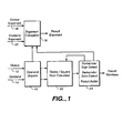
- FIG. 1 is a functional block diagram of a floating point divide and square root processor according to one embodiment of the present invention.
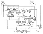
- FIG. 2 is a functional block diagram of divide/square root calculator used in the processor of FIG. 1 .
- the present invention is directed to a divide and square root processor that meets a compromise between area and speed to implement the divide function.
- the square root function is implemented using the same hardware with minimal addition. Simple hardware, and hence low area and high speed, is achieved by using a SRT Radix-2 type algorithm.
- FIG. 1 is a block diagram of the functional unit of a divide and square root processor according to one embodiment of the invention.
- the processor includes an operand unpack 10 that receives the divisor and dividend for a divide operation via busses 12 and 14 , respectively.
- An exponent calculator 16 receives the divisor exponent and dividend exponent via busses 18 and 20 , respectively.
- divisor bus 12 carries the divisor and dividend bus 14 carries the dividend.
- Divisor exponent bus 18 carries the exponent part of the divisor, and dividend exponent 20 carries the exponent part of the dividend.
- dividend bus 14 carries the operand, and dividend exponent bus 20 carries the exponent of the operand.
- Divisor bus 12 and divisor exponent bus 18 are not used for square root operations.
- the resultant exponent is calculated based on the inputs.
- the exponent is adjusted, as required, based on the final mantissa result.
- computation of the resultant exponent is based solely a on the operand (dividend) exponent.
- Divide/square root calculator 22 iteratively computes the mantissa results, 2 bits during each cycle for divide operations and 1 bit during each cycle for square root operations, and accumulates the result in a redundant number format.
- Calculator 22 employs at least two carry-save adders, arranged in a cascaded manner
- each carry-save adder generates a result bit during a respective iteration, so that during each cycle through the carry-save adders at least two result bits are accumulated in a partial remainder.
- the cascaded carry-save adders generate one result bit during each cycle.
- Each carry-save adder in calculator 22 accumulate a partial remainder based on an SRT Radix-2 algorithm. Upon completion of the process by calculator 22 , the partial remainders accumulated through the last cycle are processed by result adder 24 .
- the SRT algorithm is similar to a traditional division algorithm, where the result is computed one digit at a time. At each step a partial remainder is calculated which is used in the next step.
- the SRT division algorithm generates a partial remainder W[j+1] on each iteration of the divide operation, subtracting a multiple of the divisor from the scaled current partial remainder W[j].
- the SRT algorithm is implemented in redundant residual form.
- the carry-save adders compute the partial remainders, with each partial remainder being represented by two numbers, the sum (Ws) and the carry (Wc).
- the real value of the partial remainder is derived from the sum of Ws and Wc.
- the quotient estimate is obtained from the partial remainder.
- the square root algorithm computes one result bit during each cycle. At each iteration a partial remainder is calculated which is used in the next iteration.
- the square root algorithm generates a partial remainder W[j+1] on each iteration of the square root operation. Unlike the divide algorithm where two result bits are generated during the two iterations of each cycle, the square root algorithm generates a single result bit during each cycle.
- next result bits are computed based on the partial remainder of the prior iteration (W[j]).
- the result is accumulated in calculator 22 .
- the accumulated partial remainder is sent to the remainder zero and sign detect portion of block 24 .
- the accumulated result may be adjusted in block 24 based on the input from zero and sign detect functions.
- the remainder zero/sign detect and result adder block 24 receives input in redundant format from the divide/square root calculator 22 and generates a final 2 's compliment value. When calculator 22 outputs partial remainders, the remainder zero/sign detect portion of block 24 performs a zero detect and also checks for the sign bit of the remainder. When the calculator 22 supplies the final result in a redundant format, block 24 produces the final result in binary format.
- FIG. 2 illustrates a more detailed embodiment of divide/square root calculator 22 .
- Calculator 22 uses the SRT Radix-2 algorithm, using redundant quotient digits. While each iteration of the divide generates one bit of the quotient, the divider performs two iterations per cycle, and consequently produces two quotient bits per cycle. In the square root mode, the hardware performs one iteration per cycle, producing one result bit per cycle. The hardware required to perform one iteration is substantially duplicated to produce two quotient bits. Both the quotient and the remainder are kept redundantly within the divide unit and their components are combined subsequently to determine their value.
- divisor D is input through register 100 so that the divisor D and its complement are input to multiplexers 102 and 104 .
- Dividend X is input through register 106 to multiplexer 108 .
- Partial Remainder-Save (PRS) register 110 and Partial Remainder-Carry (PRC) register 112 store the sum (Ws) and carry (Wc) components of partial remainder (W[j ⁇ 1]) that were calculated during the prior iteration (j ⁇ 1).
- W[j ⁇ 1] and the output of multiplexer 102 are input to adder 114 , which provides the current iteration partial remainder consisting of sum (Ws[j]) and carry (Wc[j]) to selector 116 and to multiplexers 108 and 118 .
- multiplexer 104 provides the divisor D and multiplexers 108 and 118 provide the sum (Ws[j]) and carry (Wc[j]) portions of the partial remainder from the prior iteration (j) to adder 120 .
- Multiplexer 108 also supplies the dividend X to adder 120 .
- Adder 120 generates the partial remainder (Ws[j+1] and Wc[j+1]) for iteration (j+1) and supplies these to registers 110 and 112 for use by adder 114 during the next (j+2) iteration.
- Selector 116 receives the partial remainder (Ws[j] and Wc[j]) from adder 114 and selector 122 receives the partial remainder (Ws[j+1] and Wc[j+1]) from adder 120 .
- Selector 116 generates an estimated quotient bit (S j+1 ) for the next iteration (j+1) based on the four most significant bits of Wc and Ws generated by adder 114
- selector 122 generates an estimated quotient bit (S j+ 2) for the following iteration (j+2), based on the four most significant bits of Wc and Ws generated by adder 120 .
- a Radix-R algorithm produces R ⁇ 1 possible quotient bits 0 , 1 , . . . , R ⁇ 1.
- Each iteration of the divide requires an exact calculation of the current remainder to determine the next quotient bit.
- the SRT introduces redundant quotient bits. For instance, in the case of a Radix-2 algorithm, the quotient bits may be ⁇ 1, 0 and 1. With SRT, the remainder does not need to be known to an exact value for each iteration of the divide. Instead, the remainder need only be known within certain ranges. With a small enough error built into the remainder estimation, the quotient bits can be identified from the range which contains the partial remainder.
- the next partial remainder can not be more than the value of the divisor, nor can it be less than ⁇ 1*divisor. Therefore, the absolute value of the next partial remainder must be no greater than the divisor:
- Selectors 116 and 122 examine the four most significant bits Ws and Wc to perform the quotient estimation The following quotient selection logic will keep the partial remainder in bound:
- the quotient selection logic is based on the sum of the four most significant bits of Ws[j]+Wc[j]:
- Shift register 128 accumulates a record (QP) of the number of times a positive divisor was subtracted from the current partial remainder, and register 130 accumulates a record (QN) of the number of times a negative divisor was subtracted from the current partial remainder.
- QP record of the number of times a positive divisor was subtracted from the current partial remainder
- QN record of the number of times a negative divisor was subtracted from the current partial remainder.
- Multiplexer 132 provides an output from registers 128 and 130 to shift circuit 134 , which in turn provides an output to multiplexer 104 .
- Multiplexers 124 and 126 provide outputs to result adder 24 (FIG. 1 ).
- multiplexer 132 and shift circuit 134 are not used in the divide mode, and quotient bit selector 116 is not used in the square-root mode.
- the quotient bit S j+2 (or, for iteration j, S j ) selected by selector 122 is accumulated in registers 128 and 130 and is supplied to multiplexer 102 to generate the ⁇ S j *D part of the recurrence divide equation.
- adder 114 adds 2*W[j ⁇ 1] to ⁇ S j *D to produce the partial remainder W[j] in the form of sum and carry for the current iteration.
- Selector 116 supplies the estimated quotient bit S j+1 to registers 128 and 130 for the next (j+1) iteration.
- Adder 114 also supplies the sum and carry portions of the partial remainder of the j iteration to adder 120 for the j+1 iteration.
- Adder 120 generates the partial remainder for the next iteration, which is transferred to registers 110 and 112 for use by adder 114 during the next (j+2) iteration.
- the four most significant digits of the partial remainder from adder 120 are used by selector 122 to provide an estimated quotient bit (S j+2 ) for the j+2 iteration.
- registers 110 , 112 , 128 and 130 are empty, so W 0 is zero. Consequently, S 1 selected by selector 116 is 1.
- adder 120 receives zero-valued, Ws 0 and Ws 1 and generates a partial remainder of ⁇ D.
- the quotient bit S 2 is selected by selector 122 , and the partial remainder and accumulated quotient bits S 0 and S 1 are transferred by multiplexers 124 and 126 to result adder 24 (FIG. 1 ).
- another partial remainder and quotient bits S 2 and S 3 are generated and transferred to the result adder.
- Registers 128 and 130 accumulate a record of the number of times a positive divisor was subtracted from a current partial remainder (QP) and the number of times a negative divisor was subtracted from a current partial remainder (QN).
- multiplexers 124 and 126 are operated first to transfer the accumulated partial remainder from adder 120 to the result adder 24 ( FIG. 1 ) and then to transfer the accumulated quotient components of QP and QN from registers 128 and 130 to result adder 24 .
- Result adder 24 generates the value of the remainder and checks for the sign and zero value.
- a second partial remainder is generated by computing W[1]+D, where W[1] is the partial remainder after the last iteration 1 .
- the sticky bit is set based on the sign and the value of the two remainders.
- the sticky bit is an indicator of floating point precision.
- the final quotient is calculated in result adder 24 by subtracting QN from QP and adding a possible carry-in value. Since QN is stored in register 130 in 1's complement form as ⁇ overscore (QN) ⁇ , it can be added to QP. Hence, the quotient is calculated as QP+ ⁇ overscore (QN) ⁇ +carry-in.
- the carry-in is 1 if the first remainder of the divide is 0 or positive. Otherwise, the quotient must be corrected one smaller by using a carry-in of 0.
- single precision result is 26 bits (24 bits of fraction plus a guard and round bit) with the remainder determining the sticky bit.
- the double precision result is 55 its (53 bits of fraction plus a guard and round bit) with the remainder determining the sticky bit.
- the square root algorithm is similar to the divide algorithm using the same quotient select logic but with a different partial remainder calculation.
- the requirement for the quotient select is also to guaranty the partial remainder is bounded.
- the operand range is [0.5, 2], so that if the exponent of the floating point number is an odd number the mantissa may be right-shifted one bit to change the exponent to an even number.
- adders 114 and 120 are only adding a zero to the partial remainder.
- ⁇ [2QP[j]+2 ⁇ (j+1) ] is computed by shifter 134 and is supplied to adder 120 by multiplexer 104 .
- Adder 120 adds ⁇ [2QP[j]+2 ⁇ (j+1) ] to the result from adder 114 to derive W[j+1].
- Shifter circuit 134 shifts the input ‘1’ one bit to the left and forces the ⁇ (j+1) bit position to binary ‘ ⁇ 1’.
- the one bit shift effectively provides ⁇ 2QP[j] where S j+1 is ‘1’ or ⁇ 2QN[j] where S j+1 is ‘ ⁇ 1’.
- the force of a ‘1’ at the ⁇ (j+1) bit position effectively adds ⁇ 2 ⁇ (j+1) to the shifted result.
- shifter 134 shifts the partial remainder left by one-bit to ‘1010000000’, and forces a ‘1’ at the ⁇ 6 bit position ⁇ (j+1), resulting in the mantissa of the partial remainder of ‘1010010000’.
- the result is summed with Ws[j] and Wc[j] by adder 120 to derive Ws[j+1] and Wc[j+1] which are stored in registers 110 and 112 for use as Ws[j] and Wc[j], respectively, during the next iteration.
- Selector 122 selects the estimated result S j+1 , which is inserted into registers 128 and 130 as QP and ⁇ overscore (QN) ⁇ for the next iteration.
- the result of selector 116 is not used for square root function. Since both adders 114 and 120 are used to compute one iteration of square root, only one result bit is generated each cycle through the circuit.
- the result bit is estimated using the same logic as described in the divider section. The result is maintained in identical fashion and shifted into shift registers 128 and 130 , one bit at a time.
- multiplexers 124 and 126 are operated first to transfer the accumulated partial remainder from adder 120 to the result adder 24 ( FIG. 1 ) and then to transfer the accumulated values of QP and QN from registers 128 and 130 to result adder 24 .
- the result adder generates the value of the remainder and checks for the sign and zero value.
- a second partial remainder is generated by computing W[1]+(2)S ⁇ 2 ⁇ (j+1) , where S is the accumulated result to the last iteration and W[1] is the partial remainder after the last iteration 1 .
- the sticky bit is set based on the sign and the value of the two remainders.
- the accumulated result components are transferred after transfer of the accumulated partial remainder.
- the final result is calculated in result adder 24 by subtracting QN from QP as: QP+ ⁇ overscore (QN) ⁇ +carry-in.
- the carry-in is 1 if the first remainder of the divide is 0 or positive. Otherwise, the result must be corrected one smaller by using a carry-in of 0.
- single precision result is 26 bits (24 bits of fraction plus a guard and round bit) with the remainder determining the sticky bit.
- the double precision result is 55 bits (53 bits of fraction plus a guard and round bit) with the remainder determining the sticky bit.
- the initial partial remainder W[0] is calculated by adder 120 while adder 114 is bypassed.
- the mantissa calculator 22 calculates the mantissa to transfer the partial remainder from adder 120 .
- the accumulated quotient or result bits are then transferred from registers 128 and 130 .
- the result bits are accumulated for operation on adder 120 , and the partial remainder is transferred to result adder 24 .
- the partial remainder is employed by result adder 24 to generate the resulting mantissa and establish the final value of the exponent in accordance with traditional divide and square root algorithms.
- the present invention thus provides an improved floating point divide and square root processor in which the square root algorithm is mapped to the divide algorithm hardware over plural divide operations. Hence, during each cycle, the processor provides plural quotient bits in the divide mode and a single result bit in the square root mode.
- the divide and square root algorithms share a common result prediction logic. The final corrective step in the square root result is performed based on the partial remainder.
- the processor is small in size for reasonable performance and may be used for high frequency operation. While the invention is described herein as employing a Radix-2 algorithm, high performance may be achieved by duplicating the hardware or employing a higher radix algorithm. Nevertheless, use of Radix-2 algorithm permits simpler testing of the divide and square root processor, compared to multiplication-based and Radix-4-based processors.
Abstract
Description
-
- The algorithms that implement divide and square root functions are often similar. To conserve space on the IC, designers try to utilize as much of the divide hardware as possible in the implementation of the square root functions. However, these techniques have not been altogether successful. More recently, designers have implemented the divide function using the multiplier array of the arithmetic unit of the CPU, providing additional support for square root. However, the multiplier array also consumes a large amount of area on the IC, and can be frequency limited, so little is gained with this approach. Accordingly, there is a need for a divide and square root processor with improved spatial requirements.
W[j+1]=2*W[j]−S j+1 *D,
where W[j]is the partial remainder of jth iteration, D is the divisor, Sj+1 is the quotient bit for the (j+1)th iteration, and W[j+1] is the new partial remainder for the (j+1)th iteration. The SRT division algorithm generates a partial remainder W[j+1] on each iteration of the divide operation, subtracting a multiple of the divisor from the scaled current partial remainder W[j].
W[j+1]=2*W[j]−2S[j]S j+1 −S j+1 2·2−(j+1),
where W[j] is the partial remainder estimated for the j-th iteration, S[j] is the accumulated result to the j-th iteration, Sj+1 is the result bit for the (j+1)th iteration, and W[j+1) is the new partial remainder for the (j+1)th iteration. The square root algorithm generates a partial remainder W[j+1] on each iteration of the square root operation. Unlike the divide algorithm where two result bits are generated during the two iterations of each cycle, the square root algorithm generates a single result bit during each cycle.
| If 0 ≦ ˜2W[j] ≦ 3, | then Sj+1 = 1 | ||
| If ˜2W[j] = −1, | then Sj+1 = 0 | ||
| If −5 ≦ ˜2W[j] ≦ −2, | then Sj+1 = −1 | ||
The four bits of −2W[j] for quotient estimation are the four integer bits, i.e. three integer bits and one fraction bit of −W[j], represented as Y3 Y2 YL.Y0
-
- Magnitude of the quotient: Qm=!(P2&P1&P0)
- Sign of the quotient:
| Qs = P3{circumflex over ( )}(G2|P2&G1|P2&G1|P2&P1&G0) |
| Carry propagation | Pi = Ci{circumflex over ( )}Si | ||
| Carry generation | Gi = Ci&Si | ||
| Qm | Qs | Sj+1 |
| 0 | x | 0 |
| 1 | 0 | 1 |
| 1 | 1 | −1 |
Here, Ci and Si are the carry and sum part of each bit in −W[j].
-
- Initially j=0, S0=1, and W[0]=X−D,
- 1. Quotient estimation based on partial remainder W[j]: Sj+1=Qsel (W [j])
- 2. Calculate next partial remainder:
W[j+1]=2*W [j]−S j+1 *D - 3. Iteratively repeat steps 1 and 2 until all the quotient bits are generated.
| TABLE 1 |
| Quotient bit representation |
| Quotient | |||||
| Value | QP | QN | {overscore (QN)} | ||
| 1 | 1 | 0 | 1 | ||
| 0 | 0 | 0 | 1 | ||
| −1 | 0 | 1 | 0 | ||
-
- Initially j=0, S0=1, and W[0]=X−1
- 1. Quotient estimation based on W[j]:
S j+1 =Qsel (W [j]) - 2. Calculate next partial remainder W[j+1]:
W[j+1]=2W[j]−2S[j]Sj+1−Sj+1 2·2−(j+1) - 3. Iteratively repeat steps 1 and 2 until all quotient bits are generated, where W[j] is the partial remainder at step j, Sj+1 is the estimated result for step j+1, w[j+1] is the partial remainder at step j+1 and S[j] is the accumulated result to step j.
W[j+1]=2Wc[j]+2Ws[j]+2QN[j]−[2QP[j]+2−(j+1)].
In this case,
W[j+1]=2Wc[j]+2Ws[j]+2QP[j]−[2QN[j]+2−(j+1)]
In this case,
Claims (17)
Priority Applications (1)
| Application Number | Priority Date | Filing Date | Title |
|---|---|---|---|
| US09/927,139 US6847985B1 (en) | 2001-08-10 | 2001-08-10 | Floating point divide and square root processor |
Applications Claiming Priority (1)
| Application Number | Priority Date | Filing Date | Title |
|---|---|---|---|
| US09/927,139 US6847985B1 (en) | 2001-08-10 | 2001-08-10 | Floating point divide and square root processor |
Publications (1)
| Publication Number | Publication Date |
|---|---|
| US6847985B1 true US6847985B1 (en) | 2005-01-25 |
Family
ID=34063681
Family Applications (1)
| Application Number | Title | Priority Date | Filing Date |
|---|---|---|---|
| US09/927,139 Expired - Fee Related US6847985B1 (en) | 2001-08-10 | 2001-08-10 | Floating point divide and square root processor |
Country Status (1)
| Country | Link |
|---|---|
| US (1) | US6847985B1 (en) |
Cited By (42)
| Publication number | Priority date | Publication date | Assignee | Title |
|---|---|---|---|---|
| US20030115235A1 (en) * | 2001-11-22 | 2003-06-19 | Tariq Kurd | Circuitry and method for performing non-arithmetic operations |
| US20030126175A1 (en) * | 2001-11-22 | 2003-07-03 | Tariq Kurd | Circuitry for carrying out square root and division operations |
| US20030149713A1 (en) * | 2001-11-22 | 2003-08-07 | Tariq Kurd | Circuitry for carrying out an arithmetic operation |
| US20030154228A1 (en) * | 2001-11-22 | 2003-08-14 | Tariq Kurd | Circuitry for carrying out a square root operation |
| US20030187900A1 (en) * | 2001-11-21 | 2003-10-02 | Samsung Electronics Co., Ltd. | Apparatus and method for calculation of divisions and square roots |
| US20060004995A1 (en) * | 2004-06-30 | 2006-01-05 | Sun Microsystems, Inc. | Apparatus and method for fine-grained multithreading in a multipipelined processor core |
| US20060004989A1 (en) * | 2004-06-30 | 2006-01-05 | Sun Microsystems, Inc. | Mechanism for selecting instructions for execution in a multithreaded processor |
| US20060005051A1 (en) * | 2004-06-30 | 2006-01-05 | Sun Microsystems, Inc. | Thread-based clock enabling in a multi-threaded processor |
| US20060004988A1 (en) * | 2004-06-30 | 2006-01-05 | Jordan Paul J | Single bit control of threads in a multithreaded multicore processor |
| US20060020831A1 (en) * | 2004-06-30 | 2006-01-26 | Sun Microsystems, Inc. | Method and appratus for power throttling in a multi-thread processor |
| US20060179092A1 (en) * | 2005-02-10 | 2006-08-10 | Schmookler Martin S | System and method for executing fixed point divide operations using a floating point multiply-add pipeline |
| US7178005B1 (en) | 2004-06-30 | 2007-02-13 | Sun Microsystems, Inc. | Efficient implementation of timers in a multithreaded processor |
| US7185178B1 (en) | 2004-06-30 | 2007-02-27 | Sun Microsystems, Inc. | Fetch speculation in a multithreaded processor |
| US7216216B1 (en) | 2004-06-30 | 2007-05-08 | Sun Microsystems, Inc. | Register window management using first pipeline to change current window and second pipeline to read operand from old window and write operand to new window |
| US7343474B1 (en) | 2004-06-30 | 2008-03-11 | Sun Microsystems, Inc. | Minimal address state in a fine grain multithreaded processor |
| US7353364B1 (en) | 2004-06-30 | 2008-04-01 | Sun Microsystems, Inc. | Apparatus and method for sharing a functional unit execution resource among a plurality of functional units |
| US7370243B1 (en) | 2004-06-30 | 2008-05-06 | Sun Microsystems, Inc. | Precise error handling in a fine grain multithreaded multicore processor |
| US7373489B1 (en) | 2004-06-30 | 2008-05-13 | Sun Microsystems, Inc. | Apparatus and method for floating-point exception prediction and recovery |
| US7383403B1 (en) | 2004-06-30 | 2008-06-03 | Sun Microsystems, Inc. | Concurrent bypass to instruction buffers in a fine grain multithreaded processor |
| US7426630B1 (en) | 2004-06-30 | 2008-09-16 | Sun Microsystems, Inc. | Arbitration of window swap operations |
| US7434000B1 (en) | 2004-06-30 | 2008-10-07 | Sun Microsystems, Inc. | Handling duplicate cache misses in a multithreaded/multi-core processor |
| US7437538B1 (en) | 2004-06-30 | 2008-10-14 | Sun Microsystems, Inc. | Apparatus and method for reducing execution latency of floating point operations having special case operands |
| US20090006509A1 (en) * | 2007-06-28 | 2009-01-01 | Alaaeldin Amin | High-radix multiplier-divider |
| US7478225B1 (en) | 2004-06-30 | 2009-01-13 | Sun Microsystems, Inc. | Apparatus and method to support pipelining of differing-latency instructions in a multithreaded processor |
| US7533248B1 (en) | 2004-06-30 | 2009-05-12 | Sun Microsystems, Inc. | Multithreaded processor including a functional unit shared between multiple requestors and arbitration therefor |
| US7702887B1 (en) | 2004-06-30 | 2010-04-20 | Sun Microsystems, Inc. | Performance instrumentation in a fine grain multithreaded multicore processor |
| US20100115494A1 (en) * | 2008-11-03 | 2010-05-06 | Gorton Jr Richard C | System for dynamic program profiling |
| US20100146220A1 (en) * | 2008-12-04 | 2010-06-10 | Panchenko Maksim V | Efficient program instrumentation for memory profiling |
| US7747771B1 (en) | 2004-06-30 | 2010-06-29 | Oracle America, Inc. | Register access protocol in a multihreaded multi-core processor |
| US7774393B1 (en) | 2004-06-30 | 2010-08-10 | Oracle America, Inc. | Apparatus and method for integer to floating-point format conversion |
| US7861063B1 (en) | 2004-06-30 | 2010-12-28 | Oracle America, Inc. | Delay slot handling in a processor |
| US7941642B1 (en) | 2004-06-30 | 2011-05-10 | Oracle America, Inc. | Method for selecting between divide instructions associated with respective threads in a multi-threaded processor |
| US8024719B2 (en) | 2008-11-03 | 2011-09-20 | Advanced Micro Devices, Inc. | Bounded hash table sorting in a dynamic program profiling system |
| US8037250B1 (en) | 2004-12-09 | 2011-10-11 | Oracle America, Inc. | Arbitrating cache misses in a multithreaded/multi-core processor |
| US8095778B1 (en) | 2004-06-30 | 2012-01-10 | Open Computing Trust I & II | Method and system for sharing functional units of a multithreaded processor |
| US8225034B1 (en) | 2004-06-30 | 2012-07-17 | Oracle America, Inc. | Hybrid instruction buffer |
| US20160147503A1 (en) * | 2014-11-21 | 2016-05-26 | Arm Limited | Data processing apparatus having combined divide-square root circuitry |
| US9983850B2 (en) | 2015-07-13 | 2018-05-29 | Samsung Electronics Co., Ltd. | Shared hardware integer/floating point divider and square root logic unit and associated methods |
| US10152303B2 (en) * | 2016-12-13 | 2018-12-11 | Arm Limited | Partial square root calculation |
| US20180364983A1 (en) * | 2017-06-14 | 2018-12-20 | Arm Limited | Square root digit recurrence |
| US10223073B2 (en) | 2016-11-03 | 2019-03-05 | Samsung Electronics Co., Ltd | Radix 16 PD table implemented with a radix 4 PD table |
| US10706101B2 (en) | 2016-04-14 | 2020-07-07 | Advanced Micro Devices, Inc. | Bucketized hash tables with remap entries |
Citations (3)
| Publication number | Priority date | Publication date | Assignee | Title |
|---|---|---|---|---|
| US5404324A (en) * | 1993-11-01 | 1995-04-04 | Hewlett-Packard Company | Methods and apparatus for performing division and square root computations in a computer |
| US5870323A (en) * | 1995-07-05 | 1999-02-09 | Sun Microsystems, Inc. | Three overlapped stages of radix-2 square root/division with speculative execution |
| US6108682A (en) * | 1998-05-14 | 2000-08-22 | Arm Limited | Division and/or square root calculating circuit |
-
2001
- 2001-08-10 US US09/927,139 patent/US6847985B1/en not_active Expired - Fee Related
Patent Citations (3)
| Publication number | Priority date | Publication date | Assignee | Title |
|---|---|---|---|---|
| US5404324A (en) * | 1993-11-01 | 1995-04-04 | Hewlett-Packard Company | Methods and apparatus for performing division and square root computations in a computer |
| US5870323A (en) * | 1995-07-05 | 1999-02-09 | Sun Microsystems, Inc. | Three overlapped stages of radix-2 square root/division with speculative execution |
| US6108682A (en) * | 1998-05-14 | 2000-08-22 | Arm Limited | Division and/or square root calculating circuit |
Cited By (59)
| Publication number | Priority date | Publication date | Assignee | Title |
|---|---|---|---|---|
| US20030187900A1 (en) * | 2001-11-21 | 2003-10-02 | Samsung Electronics Co., Ltd. | Apparatus and method for calculation of divisions and square roots |
| US7809784B2 (en) | 2001-11-21 | 2010-10-05 | Samsung Electronics Co., Ltd. | Apparatus and method for calculation of divisions and square roots |
| US20070118584A1 (en) * | 2001-11-21 | 2007-05-24 | Samsung Electronics Co., Ltd. | Apparatus and method for calculation of divisions and square roots |
| US7185040B2 (en) * | 2001-11-21 | 2007-02-27 | Samsung Electronics Co., Ltd. | Apparatus and method for calculation of divisions and square roots |
| US7174357B2 (en) | 2001-11-22 | 2007-02-06 | Stmicroelectronics Limited | Circuitry for carrying out division and/or square root operations requiring a plurality of iterations |
| US20030126175A1 (en) * | 2001-11-22 | 2003-07-03 | Tariq Kurd | Circuitry for carrying out square root and division operations |
| US20030149713A1 (en) * | 2001-11-22 | 2003-08-07 | Tariq Kurd | Circuitry for carrying out an arithmetic operation |
| US20030154228A1 (en) * | 2001-11-22 | 2003-08-14 | Tariq Kurd | Circuitry for carrying out a square root operation |
| US7464129B2 (en) * | 2001-11-22 | 2008-12-09 | Stmicroelectronics Limited | Circuitry for carrying out a square root operation |
| US20030115235A1 (en) * | 2001-11-22 | 2003-06-19 | Tariq Kurd | Circuitry and method for performing non-arithmetic operations |
| US7395296B2 (en) | 2001-11-23 | 2008-07-01 | Stmicroelectronics Limited | Circuitry and method for performing non-arithmetic operations |
| US7437538B1 (en) | 2004-06-30 | 2008-10-14 | Sun Microsystems, Inc. | Apparatus and method for reducing execution latency of floating point operations having special case operands |
| US7676655B2 (en) | 2004-06-30 | 2010-03-09 | Sun Microsystems, Inc. | Single bit control of threads in a multithreaded multicore processor |
| US8769246B2 (en) | 2004-06-30 | 2014-07-01 | Open Computing Trust I & II | Mechanism for selecting instructions for execution in a multithreaded processor |
| US7185178B1 (en) | 2004-06-30 | 2007-02-27 | Sun Microsystems, Inc. | Fetch speculation in a multithreaded processor |
| US7216216B1 (en) | 2004-06-30 | 2007-05-08 | Sun Microsystems, Inc. | Register window management using first pipeline to change current window and second pipeline to read operand from old window and write operand to new window |
| US20060020831A1 (en) * | 2004-06-30 | 2006-01-26 | Sun Microsystems, Inc. | Method and appratus for power throttling in a multi-thread processor |
| US7330988B2 (en) | 2004-06-30 | 2008-02-12 | Sun Microsystems, Inc. | Method and apparatus for power throttling in a multi-thread processor |
| US7343474B1 (en) | 2004-06-30 | 2008-03-11 | Sun Microsystems, Inc. | Minimal address state in a fine grain multithreaded processor |
| US7353364B1 (en) | 2004-06-30 | 2008-04-01 | Sun Microsystems, Inc. | Apparatus and method for sharing a functional unit execution resource among a plurality of functional units |
| US7370243B1 (en) | 2004-06-30 | 2008-05-06 | Sun Microsystems, Inc. | Precise error handling in a fine grain multithreaded multicore processor |
| US7373489B1 (en) | 2004-06-30 | 2008-05-13 | Sun Microsystems, Inc. | Apparatus and method for floating-point exception prediction and recovery |
| US7383403B1 (en) | 2004-06-30 | 2008-06-03 | Sun Microsystems, Inc. | Concurrent bypass to instruction buffers in a fine grain multithreaded processor |
| US20060004988A1 (en) * | 2004-06-30 | 2006-01-05 | Jordan Paul J | Single bit control of threads in a multithreaded multicore processor |
| US7401206B2 (en) | 2004-06-30 | 2008-07-15 | Sun Microsystems, Inc. | Apparatus and method for fine-grained multithreading in a multipipelined processor core |
| US7426630B1 (en) | 2004-06-30 | 2008-09-16 | Sun Microsystems, Inc. | Arbitration of window swap operations |
| US7434000B1 (en) | 2004-06-30 | 2008-10-07 | Sun Microsystems, Inc. | Handling duplicate cache misses in a multithreaded/multi-core processor |
| US20060005051A1 (en) * | 2004-06-30 | 2006-01-05 | Sun Microsystems, Inc. | Thread-based clock enabling in a multi-threaded processor |
| US8225034B1 (en) | 2004-06-30 | 2012-07-17 | Oracle America, Inc. | Hybrid instruction buffer |
| US20060004989A1 (en) * | 2004-06-30 | 2006-01-05 | Sun Microsystems, Inc. | Mechanism for selecting instructions for execution in a multithreaded processor |
| US8095778B1 (en) | 2004-06-30 | 2012-01-10 | Open Computing Trust I & II | Method and system for sharing functional units of a multithreaded processor |
| US7478225B1 (en) | 2004-06-30 | 2009-01-13 | Sun Microsystems, Inc. | Apparatus and method to support pipelining of differing-latency instructions in a multithreaded processor |
| US7523330B2 (en) | 2004-06-30 | 2009-04-21 | Sun Microsystems, Inc. | Thread-based clock enabling in a multi-threaded processor |
| US7533248B1 (en) | 2004-06-30 | 2009-05-12 | Sun Microsystems, Inc. | Multithreaded processor including a functional unit shared between multiple requestors and arbitration therefor |
| US7178005B1 (en) | 2004-06-30 | 2007-02-13 | Sun Microsystems, Inc. | Efficient implementation of timers in a multithreaded processor |
| US7702887B1 (en) | 2004-06-30 | 2010-04-20 | Sun Microsystems, Inc. | Performance instrumentation in a fine grain multithreaded multicore processor |
| US7941642B1 (en) | 2004-06-30 | 2011-05-10 | Oracle America, Inc. | Method for selecting between divide instructions associated with respective threads in a multi-threaded processor |
| US7890734B2 (en) | 2004-06-30 | 2011-02-15 | Open Computing Trust I & II | Mechanism for selecting instructions for execution in a multithreaded processor |
| US7747771B1 (en) | 2004-06-30 | 2010-06-29 | Oracle America, Inc. | Register access protocol in a multihreaded multi-core processor |
| US7774393B1 (en) | 2004-06-30 | 2010-08-10 | Oracle America, Inc. | Apparatus and method for integer to floating-point format conversion |
| US20060004995A1 (en) * | 2004-06-30 | 2006-01-05 | Sun Microsystems, Inc. | Apparatus and method for fine-grained multithreading in a multipipelined processor core |
| US7861063B1 (en) | 2004-06-30 | 2010-12-28 | Oracle America, Inc. | Delay slot handling in a processor |
| US8037250B1 (en) | 2004-12-09 | 2011-10-11 | Oracle America, Inc. | Arbitrating cache misses in a multithreaded/multi-core processor |
| US20080275931A1 (en) * | 2005-02-10 | 2008-11-06 | International Business Machines Corporation | Executing Fixed Point Divide Operations Using a Floating Point Multiply-Add Pipeline |
| US20060179092A1 (en) * | 2005-02-10 | 2006-08-10 | Schmookler Martin S | System and method for executing fixed point divide operations using a floating point multiply-add pipeline |
| US8429217B2 (en) | 2005-02-10 | 2013-04-23 | International Business Machines Corporation | Executing fixed point divide operations using a floating point multiply-add pipeline |
| US20090006509A1 (en) * | 2007-06-28 | 2009-01-01 | Alaaeldin Amin | High-radix multiplier-divider |
| US8024719B2 (en) | 2008-11-03 | 2011-09-20 | Advanced Micro Devices, Inc. | Bounded hash table sorting in a dynamic program profiling system |
| US20100115494A1 (en) * | 2008-11-03 | 2010-05-06 | Gorton Jr Richard C | System for dynamic program profiling |
| US20100146220A1 (en) * | 2008-12-04 | 2010-06-10 | Panchenko Maksim V | Efficient program instrumentation for memory profiling |
| US8478948B2 (en) | 2008-12-04 | 2013-07-02 | Oracle America, Inc. | Method and system for efficient tracing and profiling of memory accesses during program execution |
| US20160147503A1 (en) * | 2014-11-21 | 2016-05-26 | Arm Limited | Data processing apparatus having combined divide-square root circuitry |
| US9785407B2 (en) * | 2014-11-21 | 2017-10-10 | Arm Limited | Data processing apparatus having combined divide-square root circuitry |
| US9983850B2 (en) | 2015-07-13 | 2018-05-29 | Samsung Electronics Co., Ltd. | Shared hardware integer/floating point divider and square root logic unit and associated methods |
| US10706101B2 (en) | 2016-04-14 | 2020-07-07 | Advanced Micro Devices, Inc. | Bucketized hash tables with remap entries |
| US10223073B2 (en) | 2016-11-03 | 2019-03-05 | Samsung Electronics Co., Ltd | Radix 16 PD table implemented with a radix 4 PD table |
| US10152303B2 (en) * | 2016-12-13 | 2018-12-11 | Arm Limited | Partial square root calculation |
| US20180364983A1 (en) * | 2017-06-14 | 2018-12-20 | Arm Limited | Square root digit recurrence |
| US10809980B2 (en) * | 2017-06-14 | 2020-10-20 | Arm Limited | Square root digit recurrence |
Similar Documents
| Publication | Publication Date | Title |
|---|---|---|
| US6847985B1 (en) | Floating point divide and square root processor | |
| Obermann et al. | Division algorithms and implementations | |
| JP3761977B2 (en) | Floating-point multiplier with reduced critical path by using delay matching technology and its operation method | |
| US6240433B1 (en) | High accuracy estimates of elementary functions | |
| JP3689183B2 (en) | Accurate and effective sticky bit calculation for accurate floating-point division / square root operations | |
| Pineiro et al. | Algorithm and architecture for logarithm, exponential, and powering computation | |
| US6360241B1 (en) | Computer method and apparatus for division and square root operations using signed digit | |
| USRE39385E1 (en) | Method and apparatus for performing mathematical functions using polynomial approximation and a rectangular aspect ratio multiplier | |
| JPH02196328A (en) | Floating point computing apparatus | |
| US7921149B2 (en) | Division and square root arithmetic unit | |
| JPH04227535A (en) | Apparatus for performing division | |
| US5184318A (en) | Rectangular array signed digit multiplier | |
| Hickmann et al. | A parallel IEEE P754 decimal floating-point multiplier | |
| WO2022170809A1 (en) | Reconfigurable floating point multiply-accumulate operation unit and method suitable for multi-precision calculation | |
| Bruguera | Low latency floating-point division and square root unit | |
| Parhami | Computing with logarithmic number system arithmetic: Implementation methods and performance benefits | |
| US8019805B1 (en) | Apparatus and method for multiple pass extended precision floating point multiplication | |
| Erle et al. | Decimal floating-point multiplication | |
| Nannarelli | Tunable floating-point for energy efficient accelerators | |
| Bruguera | Radix-64 floating-point divider | |
| US5278782A (en) | Square root operation device | |
| Gerwig et al. | High performance floating-point unit with 116 bit wide divider | |
| US5818745A (en) | Computer for performing non-restoring division | |
| US20090006509A1 (en) | High-radix multiplier-divider | |
| Ushasree et al. | VLSI implementation of a high speed single precision floating point unit using verilog |
Legal Events
| Date | Code | Title | Description |
|---|---|---|---|
| AS | Assignment |
Owner name: LSI LOGIC CORPORATION, CALIFORNIA Free format text: ASSIGNMENT OF ASSIGNORS INTEREST;ASSIGNORS:GUPTA, GAGAN V.;YU, MENGCHEN;REEL/FRAME:012067/0536;SIGNING DATES FROM 20010727 TO 20010806 |
|
| FEPP | Fee payment procedure |
Free format text: PAYOR NUMBER ASSIGNED (ORIGINAL EVENT CODE: ASPN); ENTITY STATUS OF PATENT OWNER: LARGE ENTITY |
|
| FPAY | Fee payment |
Year of fee payment: 4 |
|
| FPAY | Fee payment |
Year of fee payment: 8 |
|
| AS | Assignment |
Owner name: DEUTSCHE BANK AG NEW YORK BRANCH, AS COLLATERAL AG Free format text: PATENT SECURITY AGREEMENT;ASSIGNORS:LSI CORPORATION;AGERE SYSTEMS LLC;REEL/FRAME:032856/0031 Effective date: 20140506 |
|
| AS | Assignment |
Owner name: LSI CORPORATION, CALIFORNIA Free format text: CHANGE OF NAME;ASSIGNOR:LSI LOGIC CORPORATION;REEL/FRAME:033102/0270 Effective date: 20070406 |
|
| AS | Assignment |
Owner name: AVAGO TECHNOLOGIES GENERAL IP (SINGAPORE) PTE. LTD Free format text: ASSIGNMENT OF ASSIGNORS INTEREST;ASSIGNOR:LSI CORPORATION;REEL/FRAME:035390/0388 Effective date: 20140814 |
|
| AS | Assignment |
Owner name: AGERE SYSTEMS LLC, PENNSYLVANIA Free format text: TERMINATION AND RELEASE OF SECURITY INTEREST IN PATENT RIGHTS (RELEASES RF 032856-0031);ASSIGNOR:DEUTSCHE BANK AG NEW YORK BRANCH, AS COLLATERAL AGENT;REEL/FRAME:037684/0039 Effective date: 20160201 Owner name: LSI CORPORATION, CALIFORNIA Free format text: TERMINATION AND RELEASE OF SECURITY INTEREST IN PATENT RIGHTS (RELEASES RF 032856-0031);ASSIGNOR:DEUTSCHE BANK AG NEW YORK BRANCH, AS COLLATERAL AGENT;REEL/FRAME:037684/0039 Effective date: 20160201 |
|
| AS | Assignment |
Owner name: BANK OF AMERICA, N.A., AS COLLATERAL AGENT, NORTH CAROLINA Free format text: PATENT SECURITY AGREEMENT;ASSIGNOR:AVAGO TECHNOLOGIES GENERAL IP (SINGAPORE) PTE. LTD.;REEL/FRAME:037808/0001 Effective date: 20160201 Owner name: BANK OF AMERICA, N.A., AS COLLATERAL AGENT, NORTH Free format text: PATENT SECURITY AGREEMENT;ASSIGNOR:AVAGO TECHNOLOGIES GENERAL IP (SINGAPORE) PTE. LTD.;REEL/FRAME:037808/0001 Effective date: 20160201 |
|
| REMI | Maintenance fee reminder mailed | ||
| LAPS | Lapse for failure to pay maintenance fees | ||
| AS | Assignment |
Owner name: AVAGO TECHNOLOGIES GENERAL IP (SINGAPORE) PTE. LTD., SINGAPORE Free format text: TERMINATION AND RELEASE OF SECURITY INTEREST IN PATENTS;ASSIGNOR:BANK OF AMERICA, N.A., AS COLLATERAL AGENT;REEL/FRAME:041710/0001 Effective date: 20170119 Owner name: AVAGO TECHNOLOGIES GENERAL IP (SINGAPORE) PTE. LTD Free format text: TERMINATION AND RELEASE OF SECURITY INTEREST IN PATENTS;ASSIGNOR:BANK OF AMERICA, N.A., AS COLLATERAL AGENT;REEL/FRAME:041710/0001 Effective date: 20170119 |
|
| STCH | Information on status: patent discontinuation |
Free format text: PATENT EXPIRED DUE TO NONPAYMENT OF MAINTENANCE FEES UNDER 37 CFR 1.362 |
|
| FP | Lapsed due to failure to pay maintenance fee |
Effective date: 20170125 |