US6854343B2 - Torque sensor for electric power-assisted steering systems - Google Patents

Torque sensor for electric power-assisted steering systems Download PDF

Info

Publication number
US6854343B2
US6854343B2 US10/165,878 US16587802A US6854343B2 US 6854343 B2 US6854343 B2 US 6854343B2 US 16587802 A US16587802 A US 16587802A US 6854343 B2 US6854343 B2 US 6854343B2
Authority
US
United States
Prior art keywords
carrier
shaft
movement
sensor
sensor according
Prior art date
Legal status (The legal status is an assumption and is not a legal conclusion. Google has not performed a legal analysis and makes no representation as to the accuracy of the status listed.)
Expired - Lifetime, expires
Application number
US10/165,878
Other versions
US20030024325A1 (en
Inventor
Nouhad Bachnak
Stefan Stross
Current Assignee (The listed assignees may be inaccurate. Google has not performed a legal analysis and makes no representation or warranty as to the accuracy of the list.)
TE Connectivity Germany GmbH
Original Assignee
Tyco Electronics AMP GmbH
Priority date (The priority date is an assumption and is not a legal conclusion. Google has not performed a legal analysis and makes no representation as to the accuracy of the date listed.)
Filing date
Publication date
Application filed by Tyco Electronics AMP GmbH filed Critical Tyco Electronics AMP GmbH
Assigned to TYCO ELECTRONICS AMP GMBH reassignment TYCO ELECTRONICS AMP GMBH ASSIGNMENT OF ASSIGNORS INTEREST (SEE DOCUMENT FOR DETAILS). Assignors: BACHNAK, NOUHAD, STROSS, STEFAN
Publication of US20030024325A1 publication Critical patent/US20030024325A1/en
Application granted granted Critical
Publication of US6854343B2 publication Critical patent/US6854343B2/en
Assigned to TE CONNECTIVITY GERMANY GMBH reassignment TE CONNECTIVITY GERMANY GMBH CHANGE OF NAME (SEE DOCUMENT FOR DETAILS). Assignors: TYCO ELECTRONICS AMP GMBH
Adjusted expiration legal-status Critical
Expired - Lifetime legal-status Critical Current

Links

Images

Classifications

    • GPHYSICS
    • G01MEASURING; TESTING
    • G01LMEASURING FORCE, STRESS, TORQUE, WORK, MECHANICAL POWER, MECHANICAL EFFICIENCY, OR FLUID PRESSURE
    • G01L5/00Apparatus for, or methods of, measuring force, work, mechanical power, or torque, specially adapted for specific purposes
    • G01L5/22Apparatus for, or methods of, measuring force, work, mechanical power, or torque, specially adapted for specific purposes for measuring the force applied to control members, e.g. control members of vehicles, triggers
    • G01L5/221Apparatus for, or methods of, measuring force, work, mechanical power, or torque, specially adapted for specific purposes for measuring the force applied to control members, e.g. control members of vehicles, triggers to steering wheels, e.g. for power assisted steering
    • GPHYSICS
    • G01MEASURING; TESTING
    • G01LMEASURING FORCE, STRESS, TORQUE, WORK, MECHANICAL POWER, MECHANICAL EFFICIENCY, OR FLUID PRESSURE
    • G01L3/00Measuring torque, work, mechanical power, or mechanical efficiency, in general
    • G01L3/02Rotary-transmission dynamometers
    • G01L3/04Rotary-transmission dynamometers wherein the torque-transmitting element comprises a torsionally-flexible shaft
    • G01L3/10Rotary-transmission dynamometers wherein the torque-transmitting element comprises a torsionally-flexible shaft involving electric or magnetic means for indicating

Definitions

  • the invention relates to a sensor for detecting the torque on a shaft such as a steering shaft.
  • Torque sensors for steering shafts are already known.
  • DE 198 34 897 C1 discloses a sensor of this type used in power-assisted steering systems of modern motor vehicles to measure the forces acting on the steering assembly. The measured values obtained in this way are then supplied as controlled variables to a control unit which calculates a signal for a preferably electric or electrohydraulic power-assisted steering system.
  • These systems typically operate such that when the steering actuating force is below a predetermined torque threshold, power assist is minimized so the driver has to apply most of the steering force. Mechanical feedback is thus imparted to the driver. Above the predetermined torque threshold, the control unit provides power assistance and therefore uniform steering actuating force, so the steering actuating force to be applied by the driver is always within a comfortable range.
  • the “spongy driving sensation” frequently criticised previously in power-assisted steering systems can therefore be avoided.
  • the sensor shown in DE 198 34 897 C1 is used to detect the rotational forces in a portion of the steering shaft so that the forces introduced into the steering shaft are transmitted by a torsion bar having a measuring cell.
  • the steering force introduced therefore causes torsion which is detected by the measuring cell and measured, for example, as a strain by strain gauges (DMS).
  • DMS strain by strain gauges
  • a torsional angle limit is provided in the known sensor and this limits the difference in the twisting angle between the two portions of the steering shaft connected the sensor, so that malfunctioning of the measuring cell, for example by overloading and rupture of the torsion bar, does not lead to complete failure of the steering assembly.
  • sensors based on DMS and optical sensors are used in the automotive industry for torque measurement based on the measuring principle of evaluating torsion.
  • twisting of a torsion bar causes extension or compression of regions of its periphery and a resultant change in the resistance of the DMS. This change in resistance is evaluated and converted into a torque measurement.
  • transmission of the signals from the DMS to the electronic evaluation device involves contact so that a special coil spring including a cable and a housing for cable guidance about the steering shaft is required for this purpose.
  • Optical torque sensors have two masks which twist relative to one another when a torque is applied to the torsion bar.
  • the light source and the receiver are secured to the housing. Relative twisting of the masks with respect to one another causes the receiver to detect a relatively large luminous flux and accordingly gives off a proportionally large signal current. While signal transmission is contactless in the optical sensors, the measuring arrangement is sensitive to strong vibrations that as occur in vehicles.
  • the invention provides a sensor having a disc-shaped movement converter being mechanically connected to a first portion of a shaft such that a torsion in the shaft or a torsion bar produces an angular movement of the movement converter.
  • a carrier surrounds the shaft in the form of a sleeve and is floatingly mounted thereon.
  • One end of the carrier is directed toward the movement converter which is mechanically connected thereto in such a way that the twisting angle movement of the movement converter is converted into forces acting on the carrier with a helical line of action.
  • the other end of the carrier is designed as a connecting piece and cooperates with a movement guide rigidly connected to the second portion of the shaft in such a way that the carrier cannot move helically but only linearly in the axial direction on the shaft.
  • a displacement sensor is provided so that the relative axial position of the carrier can be detected to determined the torque of the shaft by converting the twisting angle movement into an axial translation movement of the carrier.
  • the arrangement of this invention converts the rotational movement caused by the torque, into a translation movement namely travel of the carrier.
  • This allows the torque on a torsion bar or on a torsion shaft to be detected using contactless position sensors such as displacement sensors, which operate on an inductive or magnetic field basis, for example Hall, PLCD or differential throttle sensors.
  • FIG. 1 is a lateral section of a sensor according to the invention
  • FIG. 2 is a cross sectional view of the sensor taken along the line X—X of FIG. 1 ,
  • FIG. 3 is a perspective view of the movement converter
  • FIG. 4 is a perspective view of the carrier
  • FIG. 5 is a perspective view of the movement guide of the sensor
  • FIG. 6 is a partially sectional perspective view of the sensor
  • FIG. 7 is a perspective view of the sensor from a different viewpoint to FIG. 6 .
  • FIG. 1 shows a sectional side view of a sensor substantially consisting of the two portions 1 and 2 of a steering shaft, the movement converter 4 , the carrier 5 , the movement guide 6 and the displacement sensor element 8 .
  • a steering wheel (not shown) of a motor vehicle is connected to the portion 2 .
  • the carrier 5 surrounding the shaft 1 and 2 like a sleeve is floatingly mounted with a fit 11 on the shaft 1 and 2 .
  • the carrier 5 can consequently be moved laterally, in other words along an axis of the shaft 1 and 2 .
  • the relative lateral position of the carrier 5 with respect to a measuring device arranged outside of the shaft 1 and 2 , in particular a displacement sensor element 8 is evaluated for the measurement of the torque.
  • a magnet 7 for example, can be arranged in a defined position on the carrier 5 for interaction with the displacement sensors.
  • FIGS. 3 to 5 showing three essential individual components of the sensor, each in perspective view.
  • the disc-shaped movement converter 4 is shown in FIG. 3 with a central aperture provided for fastening to the first portion 1 of the shaft.
  • three recesses 9 are uniformly distributed over the periphery.
  • One respective side of each recess 9 is designed as an oblique and bent-in or helical running face 14 .
  • the carrier 5 in FIG. 4 consists of the central sleeve-like portion 19 formed with an extension 15 at one end into which the movement converter 4 can be fitted in such a way that the pins 10 engage in the recesses 9 .
  • the other end of the carrier 5 is designed as a connecting piece 16 comprising elongate extensions 17 projecting in the axial direction and guided in corresponding grooves 18 of the movement guide 6 ( FIG. 7 ) shown in FIG. 5 .
  • the two portions 1 and 2 of the shaft are connected to one another merely by means of the torsion bar 3 .
  • the torsion bar 3 twists about a maximum of approximately +/ ⁇ 5°.
  • the twisting or angular motion of the torsion bar 3 is linearly proportional to the torque applied thereto.
  • the portions 1 and 2 adjoining one another at the partition 12 are, as shown in FIG. 1 , designed in such a way that the two portions have respective claws which engage complementary grooves.
  • This construction acts as a torsion angle limit and is described in detail in the above-mentioned DE 198 34 897 C1.
  • the movement converter 4 is rigidly connected to the portion 1 of the steering column and the movement guide 6 is rigidly connected to the portion 2 of the steering column 2 and has at least one guide groove 18 .
  • the magnet 7 is in turn rigidly connected to the carrier 5 .
  • the carrier 5 is floatingly mounted with a fit 11 on the steering column 1 and 2 , the fit 11 serving for precise movement guidance.
  • the pins 10 are located in the carrier 5 on the running faces 14 of the movement converter 4 and are biased by a spring 13 against this running face 14 .
  • the pins 10 glide along the running faces 14 and accordingly attempt to helically move the carrier 5 as a whole, i.e. to rotate and laterally displace it simultaneously.
  • the rotational movement of the carrier 5 is eliminated by the movement guide 6 which is rigidly connected to the portion 2 of the steering column. Movement is only possible in the axial direction, so that the angular movement of the torsion bar 3 is converted into a displacement of the magnet 7 .
  • the position of the magnet 7 relative to the displacement sensor element 8 is evaluated by the electronic device and the torque consequently determined.
  • the output signal is linearly proportional to the lateral displacement or travel of the magnet 7 .
  • the torsion bar 3 can have a thickness of approximately 5 mm at the point of taper.
  • the thickness of the movement converter disc 4 is approximately 10 mm, of which approximately 5 mm are available for the screwing movement.
  • the effective travel depends on the diameter of the movement converter disc 4 and on the pitch of the slightly helical running face 14 . With a diameter of approximately 45 mm travel of the carrier 5 of for example approximately +/ ⁇ 2.5 mm results.
  • the constructional design can also be configured differently from that illustrated with the same functional principle.
  • the spring 13 for example, can be removed if the pins 10 are forcibly guided in a groove instead of in the recess 9 in both directions of movement. Because of the integration of the movement guide 6 and the movement converter 4 in the steering column 1 and 2 , the number of components can be reduced and the mechanism designed more compactly.
  • the torque sensor can also be attached to the pinion shaft to measure the torque on the steering assembly.
  • the advantages over known DMS measurement consist in the contactless transmission of the signals and in the omission of a coil spring.
  • the robust, vibration-insensitive design is advantageous in comparison with optical sensors, and is particularly useful when using a PLCD (permanent linear magnet contactless displacement) sensor.
  • the invention provides an inexpensive alternative to the above-described known sensors.
  • the movement converter and/or the movement guide can be integrated in the shaft.
  • the movement converter comprises at least one trench-like recess at its periphery, the recess being designed at least at one trench side as a running face extending slightly helically with respect to the axial direction, and in that the end of the carrier directed toward the movement converter is widened in such a way that a respective radially inwardly arranged pin engages from the outside in the recess of the movement converter, the guide means provided causing the pin to rest on the running face.
  • An embodiment of the sensor according to the invention in which a spring is arranged between movement converter and carrier and with the aid of which the pin is pressed against the running face is particularly well suited to this purpose.
  • a further particularly advantageous embodiment of the sensor using a displacement sensor based on a magnet is provided in that non-magnetic partitions are provided between the carrier with the magnet and the displacement sensor element, through which partitions the sensor can be controlled, and this is a substantial advantage in particular in conjunction with steering or gearing housings.
  • the applications of the sensor according to the invention are not limited to torque measurements in steering assemblies. It can also be provided in other applications functioning on the basis of a torsion bar. In particular in relatively short shafts, for example in household appliances, the sensor can also be attached without torsion bar, directly to a torsion shaft, the two portions 1 and 2 simply being provided by the opposing ends of the one-piece torsion shaft.

Abstract

Torsion in a shaft with two portions or a torsion bar caused by a torque is initially converted into an angular movement of a disc-shaped movement converter fastened to the first portion. A carrier surrounding the shaft as a sleeve is fastened to the second portion and converts the angular movement into an axial translation movement of the carrier which can be detected by a contactless displacement sensor.

Description

FIELD OF THE INVENTION
The invention relates to a sensor for detecting the torque on a shaft such as a steering shaft.
DESCRIPTION OF THE PRIOR ART
Torque sensors for steering shafts are already known. For example, DE 198 34 897 C1 discloses a sensor of this type used in power-assisted steering systems of modern motor vehicles to measure the forces acting on the steering assembly. The measured values obtained in this way are then supplied as controlled variables to a control unit which calculates a signal for a preferably electric or electrohydraulic power-assisted steering system. These systems typically operate such that when the steering actuating force is below a predetermined torque threshold, power assist is minimized so the driver has to apply most of the steering force. Mechanical feedback is thus imparted to the driver. Above the predetermined torque threshold, the control unit provides power assistance and therefore uniform steering actuating force, so the steering actuating force to be applied by the driver is always within a comfortable range. The “spongy driving sensation” frequently criticised previously in power-assisted steering systems can therefore be avoided.
The sensor shown in DE 198 34 897 C1 is used to detect the rotational forces in a portion of the steering shaft so that the forces introduced into the steering shaft are transmitted by a torsion bar having a measuring cell. The steering force introduced therefore causes torsion which is detected by the measuring cell and measured, for example, as a strain by strain gauges (DMS). For safety reasons, a torsional angle limit is provided in the known sensor and this limits the difference in the twisting angle between the two portions of the steering shaft connected the sensor, so that malfunctioning of the measuring cell, for example by overloading and rupture of the torsion bar, does not lead to complete failure of the steering assembly.
In particular, sensors based on DMS and optical sensors are used in the automotive industry for torque measurement based on the measuring principle of evaluating torsion.
With sensors based on DMS, twisting of a torsion bar causes extension or compression of regions of its periphery and a resultant change in the resistance of the DMS. This change in resistance is evaluated and converted into a torque measurement. However, transmission of the signals from the DMS to the electronic evaluation device involves contact so that a special coil spring including a cable and a housing for cable guidance about the steering shaft is required for this purpose.
Optical torque sensors, on the other hand, have two masks which twist relative to one another when a torque is applied to the torsion bar. The light source and the receiver are secured to the housing. Relative twisting of the masks with respect to one another causes the receiver to detect a relatively large luminous flux and accordingly gives off a proportionally large signal current. While signal transmission is contactless in the optical sensors, the measuring arrangement is sensitive to strong vibrations that as occur in vehicles.
What is needed is an improved contactless but inexpensive torque sensor that is adaptable to the high vibration environment of a vehicle.
SUMMARY OF THE INVENTION
The invention provides a sensor having a disc-shaped movement converter being mechanically connected to a first portion of a shaft such that a torsion in the shaft or a torsion bar produces an angular movement of the movement converter.
A carrier surrounds the shaft in the form of a sleeve and is floatingly mounted thereon. One end of the carrier is directed toward the movement converter which is mechanically connected thereto in such a way that the twisting angle movement of the movement converter is converted into forces acting on the carrier with a helical line of action. The other end of the carrier is designed as a connecting piece and cooperates with a movement guide rigidly connected to the second portion of the shaft in such a way that the carrier cannot move helically but only linearly in the axial direction on the shaft.
A displacement sensor is provided so that the relative axial position of the carrier can be detected to determined the torque of the shaft by converting the twisting angle movement into an axial translation movement of the carrier.
The arrangement of this invention converts the rotational movement caused by the torque, into a translation movement namely travel of the carrier. This allows the torque on a torsion bar or on a torsion shaft to be detected using contactless position sensors such as displacement sensors, which operate on an inductive or magnetic field basis, for example Hall, PLCD or differential throttle sensors.
BRIEF DESCRIPTION OF THE DRAWINGS
The invention will now be described by way of example with reference to the accompanying figures of which:
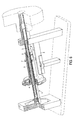
FIG. 1 is a lateral section of a sensor according to the invention,
FIG. 2 is a cross sectional view of the sensor taken along the line X—X of FIG. 1,
FIG. 3 is a perspective view of the movement converter,
FIG. 4 is a perspective view of the carrier,
FIG. 5 is a perspective view of the movement guide of the sensor,
FIG. 6 is a partially sectional perspective view of the sensor,
FIG. 7 is a perspective view of the sensor from a different viewpoint to FIG. 6.
DETAILED DESCRIPTION OF THE PREFERRED EMBODIMENT
FIG. 1 shows a sectional side view of a sensor substantially consisting of the two portions 1 and 2 of a steering shaft, the movement converter 4, the carrier 5, the movement guide 6 and the displacement sensor element 8. A steering wheel (not shown) of a motor vehicle is connected to the portion 2. The carrier 5 surrounding the shaft 1 and 2 like a sleeve is floatingly mounted with a fit 11 on the shaft 1 and 2. The carrier 5 can consequently be moved laterally, in other words along an axis of the shaft 1 and 2. The relative lateral position of the carrier 5 with respect to a measuring device arranged outside of the shaft 1 and 2, in particular a displacement sensor element 8, is evaluated for the measurement of the torque. A magnet 7, for example, can be arranged in a defined position on the carrier 5 for interaction with the displacement sensors.
Reference is now made to FIGS. 3 to 5 showing three essential individual components of the sensor, each in perspective view. The disc-shaped movement converter 4 is shown in FIG. 3 with a central aperture provided for fastening to the first portion 1 of the shaft. In addition, three recesses 9 are uniformly distributed over the periphery. One respective side of each recess 9 is designed as an oblique and bent-in or helical running face 14.
The carrier 5 in FIG. 4 consists of the central sleeve-like portion 19 formed with an extension 15 at one end into which the movement converter 4 can be fitted in such a way that the pins 10 engage in the recesses 9. The other end of the carrier 5 is designed as a connecting piece 16 comprising elongate extensions 17 projecting in the axial direction and guided in corresponding grooves 18 of the movement guide 6 (FIG. 7) shown in FIG. 5.
Reference will now be made to FIG. 1 for further explanation and, in particular, the operation of the sensor resulting from the cooperation of the individual components. The two portions 1 and 2 of the shaft are connected to one another merely by means of the torsion bar 3. During a steering process the torsion bar 3 twists about a maximum of approximately +/−5°. The twisting or angular motion of the torsion bar 3 is linearly proportional to the torque applied thereto.
The portions 1 and 2 adjoining one another at the partition 12 are, as shown in FIG. 1, designed in such a way that the two portions have respective claws which engage complementary grooves. This construction acts as a torsion angle limit and is described in detail in the above-mentioned DE 198 34 897 C1.
The movement converter 4 is rigidly connected to the portion 1 of the steering column and the movement guide 6 is rigidly connected to the portion 2 of the steering column 2 and has at least one guide groove 18. The magnet 7 is in turn rigidly connected to the carrier 5.
The carrier 5 is floatingly mounted with a fit 11 on the steering column 1 and 2, the fit 11 serving for precise movement guidance. At one end the pins 10 are located in the carrier 5 on the running faces 14 of the movement converter 4 and are biased by a spring 13 against this running face 14. Upon twisting of the torsion bar 3 the pins 10 glide along the running faces 14 and accordingly attempt to helically move the carrier 5 as a whole, i.e. to rotate and laterally displace it simultaneously. However, at the other end of the carrier 5 the rotational movement of the carrier 5 is eliminated by the movement guide 6 which is rigidly connected to the portion 2 of the steering column. Movement is only possible in the axial direction, so that the angular movement of the torsion bar 3 is converted into a displacement of the magnet 7.
The position of the magnet 7 relative to the displacement sensor element 8 is evaluated by the electronic device and the torque consequently determined. With a linear position sensor having a permanent magnet, the output signal is linearly proportional to the lateral displacement or travel of the magnet 7.
For example, the torsion bar 3 can have a thickness of approximately 5 mm at the point of taper. The thickness of the movement converter disc 4 is approximately 10 mm, of which approximately 5 mm are available for the screwing movement. The effective travel depends on the diameter of the movement converter disc 4 and on the pitch of the slightly helical running face 14. With a diameter of approximately 45 mm travel of the carrier 5 of for example approximately +/−2.5 mm results.
The constructional design can also be configured differently from that illustrated with the same functional principle. The spring 13 for example, can be removed if the pins 10 are forcibly guided in a groove instead of in the recess 9 in both directions of movement. Because of the integration of the movement guide 6 and the movement converter 4 in the steering column 1 and 2, the number of components can be reduced and the mechanism designed more compactly.
The torque sensor can also be attached to the pinion shaft to measure the torque on the steering assembly.
The advantages over known DMS measurement consist in the contactless transmission of the signals and in the omission of a coil spring. The robust, vibration-insensitive design is advantageous in comparison with optical sensors, and is particularly useful when using a PLCD (permanent linear magnet contactless displacement) sensor.
With regard to cost-efficiency the invention provides an inexpensive alternative to the above-described known sensors. In many applications the movement converter and/or the movement guide can be integrated in the shaft.
The mechanical connection between movement converter and the carrier can be made in different ways depending on the circumstances. In a relatively inexpensive design, the movement converter comprises at least one trench-like recess at its periphery, the recess being designed at least at one trench side as a running face extending slightly helically with respect to the axial direction, and in that the end of the carrier directed toward the movement converter is widened in such a way that a respective radially inwardly arranged pin engages from the outside in the recess of the movement converter, the guide means provided causing the pin to rest on the running face.
An embodiment of the sensor according to the invention in which a spring is arranged between movement converter and carrier and with the aid of which the pin is pressed against the running face is particularly well suited to this purpose.
A further particularly advantageous embodiment of the sensor using a displacement sensor based on a magnet is provided in that non-magnetic partitions are provided between the carrier with the magnet and the displacement sensor element, through which partitions the sensor can be controlled, and this is a substantial advantage in particular in conjunction with steering or gearing housings.
By using this mechanism it is possible to place the control magnets of a sensor on the steering column while the sensor element itself and the electronic evaluation device can be attached to the car body.
The applications of the sensor according to the invention are not limited to torque measurements in steering assemblies. It can also be provided in other applications functioning on the basis of a torsion bar. In particular in relatively short shafts, for example in household appliances, the sensor can also be attached without torsion bar, directly to a torsion shaft, the two portions 1 and 2 simply being provided by the opposing ends of the one-piece torsion shaft.

Claims (20)

1. A Sensor for detecting the torque on a shaft having two coaxially arranged portions, the first and second portions being connected by a torsion bar so that a torque acting on the shaft can be evaluated by the twisting of the torsion bar, the sensor comprising:
a disc-shaped movement converter being connected to the first portion of the shaft such that a torsion in the torsion bar produces an angular movement of the movement converter,
a carrier surrounding the shaft and being floatingly mounted thereon with a fit, a first end of the carrier being directed toward the movement converter and mechanically connected thereto in such a way that the angular movement of the movement converter is converted into helical forces acting on the carrier, a second end of the carrier is located to be in cooperation with a movement guide being mechanically connected to the second portion of the shaft in such a way that the carrier cannot move helically but only linearly in the axial direction on the shaft, and
a displacement sensor positioned adjacent the carrier so that the torque of the shaft can be determined by the angular movement converted into an axial translation movement of the carrier.
2. The sensor according to claim 1, wherein the movement converter has at least one recess along its periphery, the at least one recess having a running face extending slightly helically with respect to the axial direction.
3. The sensor according to claim 2 wherein the first end of the carrier comprises a radially inwardly arranged pin which engages the running face of the movement converter.
4. The sensor according to claim 3, further comprising a spring being arranged between movement converter and carrier and biased against the running face.
5. The sensor according to claim 3 wherein the recess in the movement converter is formed as a groove in which the pin can be forcibly guided in both directions of torsion and rotational movement.
6. The sensor according to claim 5 further comprising three recesses being uniformly distributed over the periphery of the movement converter.
7. The sensor according to claim 6 wherein the movement converter is integral with the shaft.
8. The sensor according to claim 6 wherein the movement guide is integral with the shaft.
9. The sensor according to claim 8 wherein the connecting piece comprises elongate extensions extending in the axial direction and guided in corresponding grooves in the movement guide.
10. The sensor according to claim 9 wherein the displacement sensor includes a displacement element positioned external the shaft and a magnet arranged on the carrier and mechanically connected thereto.
11. The sensor according to claim 9 further comprising a PLCD sensor or a Hall sensor arranged on the carrier to measure linear motion of the carrier relative to the shaft.
12. The sensor according to claim 9 further comprising a differential throttle sensor arranged on the carrier to measure linear motion of the carrier relative to the shaft.
13. The sensor according to claim 10 further comprising non-magnetic partitions provided between the carrier with the magnet and the displacement sensor element.
14. A Sensor for detecting the torque on a shaft having coaxial first and second portions, the first and second portions being connected by a torsion bar so that a torque acting on the shaft can be evaluated by the twisting of the torsion bar, the sensor comprising:
a disc-shaped movement converter having a plurality of helical running faces and being connected to the first portion of the shaft such that a torsion in the torsion bar produces an angular movement of the movement converter,
a movement guide connected to the second portion of the shaft;
a carrier mounted surrounding the shaft and axially gloating thereon, a first end of the carrier being connected to the helical running faces of the movement converter, converting the angular movement of the movement converter into helical forces acting on the carrier, a second end of the carrier cooperating with the movement guide to limit the carrier to linearly motion in the axial direction on the shaft, and
a displacement sensor positioned adjacent the carrier so that the torque of the shaft can be determined by the angular movement converted into an axial translation movement of the carrier.
15. The sensor according to claim 14 wherein the first end of the carrier comprises a radially inwardly arranged pin which engages the running face of the movement converter.
16. The sensor according to claim 15, further comprising a spring being arranged between the movement converter and the carrier and biased against the running face.
17. The sensor according to claim 16 further comprising three recesses being uniformly distributed over the periphery of the movement converter.
18. The sensor according to claim 14 wherein the displacement sensor includes a displacement element positioned external the shaft and a magnet arranged on the carrier and mechanically connected thereto.
19. The sensor according to claim 14 further comprising a PLCD sensor or a Hall sensor arranged on the carrier to measure linear motion of the carrier relative to the shaft.
20. The sensor according to claim 14 further comprising a differential throttle sensor arranged on the carrier to measure linear motion of the carrier relative to the shaft.
US10/165,878 2001-06-29 2002-06-10 Torque sensor for electric power-assisted steering systems Expired - Lifetime US6854343B2 (en)

Applications Claiming Priority (2)

Application Number Priority Date Filing Date Title
EP01115949 2001-06-29
EP01115949.8 2001-06-29

Publications (2)

Publication Number Publication Date
US20030024325A1 US20030024325A1 (en) 2003-02-06
US6854343B2 true US6854343B2 (en) 2005-02-15

Family

ID=8177906

Family Applications (1)

Application Number Title Priority Date Filing Date
US10/165,878 Expired - Lifetime US6854343B2 (en) 2001-06-29 2002-06-10 Torque sensor for electric power-assisted steering systems

Country Status (3)

Country Link
US (1) US6854343B2 (en)
AT (1) ATE314632T1 (en)
DE (1) DE60208268T2 (en)

Cited By (2)

* Cited by examiner, † Cited by third party
Publication number Priority date Publication date Assignee Title
US20090293639A1 (en) * 2008-04-11 2009-12-03 Katy Schmeisser Torque Sensor
US20110167920A1 (en) * 2008-07-14 2011-07-14 Continental Teves Ag & Co. Ohg Torque sensor arrangement with rotational angle index detection

Citations (10)

* Cited by examiner, † Cited by third party
Publication number Priority date Publication date Assignee Title
US4228591A (en) * 1976-02-12 1980-10-21 Maag Gear Wheel & Machine Co. Ltd. Measurement sensing devices
US4577716A (en) * 1984-06-21 1986-03-25 Peter Norton Servo steering system
US5232417A (en) * 1990-04-25 1993-08-03 Viscodrive Gmbh Differential drive
US5233906A (en) * 1991-05-24 1993-08-10 A. E. Bishop & Associates Mechanical centering mechanism for rotary valve power steering system
US5712563A (en) * 1994-06-13 1998-01-27 Honda Giken Kogyo Kabushiki Kaisha Steering torque sensor utilizing a displacement detector having a pulse power supply
US5824255A (en) * 1994-10-28 1998-10-20 The Boeing Company Honeycomb core forming process
DE19834897C1 (en) 1998-08-03 1999-10-21 Mannesmann Vdo Ag Torque sensor manufacturing method e.g. for automobile servo steering torque sensor
US6318188B1 (en) * 1999-06-01 2001-11-20 Mitsubishi Denki Kabushiki Kaisha Torque detector
US6364050B1 (en) * 1999-01-15 2002-04-02 Trw Lucas Varity Electric Steering Ltd. Electrical power assisted steering assemblies
US6513394B1 (en) * 1998-07-24 2003-02-04 Siemens Vdo Automotive Ag Torque sensor

Patent Citations (10)

* Cited by examiner, † Cited by third party
Publication number Priority date Publication date Assignee Title
US4228591A (en) * 1976-02-12 1980-10-21 Maag Gear Wheel & Machine Co. Ltd. Measurement sensing devices
US4577716A (en) * 1984-06-21 1986-03-25 Peter Norton Servo steering system
US5232417A (en) * 1990-04-25 1993-08-03 Viscodrive Gmbh Differential drive
US5233906A (en) * 1991-05-24 1993-08-10 A. E. Bishop & Associates Mechanical centering mechanism for rotary valve power steering system
US5712563A (en) * 1994-06-13 1998-01-27 Honda Giken Kogyo Kabushiki Kaisha Steering torque sensor utilizing a displacement detector having a pulse power supply
US5824255A (en) * 1994-10-28 1998-10-20 The Boeing Company Honeycomb core forming process
US6513394B1 (en) * 1998-07-24 2003-02-04 Siemens Vdo Automotive Ag Torque sensor
DE19834897C1 (en) 1998-08-03 1999-10-21 Mannesmann Vdo Ag Torque sensor manufacturing method e.g. for automobile servo steering torque sensor
US6364050B1 (en) * 1999-01-15 2002-04-02 Trw Lucas Varity Electric Steering Ltd. Electrical power assisted steering assemblies
US6318188B1 (en) * 1999-06-01 2001-11-20 Mitsubishi Denki Kabushiki Kaisha Torque detector

Cited By (4)

* Cited by examiner, † Cited by third party
Publication number Priority date Publication date Assignee Title
US20090293639A1 (en) * 2008-04-11 2009-12-03 Katy Schmeisser Torque Sensor
US8109156B2 (en) * 2008-04-11 2012-02-07 Liebnerr-Aerospace Lindenberg GmbH Torque sensor
US20110167920A1 (en) * 2008-07-14 2011-07-14 Continental Teves Ag & Co. Ohg Torque sensor arrangement with rotational angle index detection
US8607650B2 (en) * 2008-07-14 2013-12-17 Continental Teves Ag & Co. Ohg Torque sensor arrangement with rotational angle index detection

Also Published As

Publication number Publication date
DE60208268T2 (en) 2006-08-31
ATE314632T1 (en) 2006-01-15
US20030024325A1 (en) 2003-02-06
DE60208268D1 (en) 2006-02-02

Similar Documents

Publication Publication Date Title
US7555963B2 (en) Torque sensor
US10895278B2 (en) Apparatus for limiting rotation of steering wheel
EP1291264B1 (en) Apparatus and method for detecting absolute position
JP5440754B2 (en) Torque detector, electric power steering apparatus, and method of manufacturing torque detector
KR101098117B1 (en) Torque Sensor and Electronic Power Steering Apparatus Having Same
JPH03223635A (en) Steering-torque detecting apparatus
KR102105190B1 (en) Shift-by-wire device and shift method usig tehreof
KR20130063231A (en) Pinion sensor assembly and pinion sensor cover assembly and electric power steering apparatus having the same
JP3861778B2 (en) Torque sensor, electric power steering apparatus using the torque sensor, and method for manufacturing the electric power steering apparatus
EP3671157B1 (en) Torque sensor and steering device
US5027915A (en) Electric power steering system
KR101549815B1 (en) Torque Sensor of Electronic Power Steering Apparatus
EP1271120B1 (en) Torque sensor for electronic power-assisted steering systems
US11427250B2 (en) Rotary sensor assembly and rear wheel steering system including the same
US6854343B2 (en) Torque sensor for electric power-assisted steering systems
JP2000055751A (en) Sensor and manufacture thereof with rotary angle limitation equipment for detecting rotary torque
EP0205812B1 (en) Torque transducer coupling
EP1905672B1 (en) Electric power steering system
JPH08225083A (en) Steering assembly and method thereof
JP2000095120A (en) Support structure of pinion shaft in electrically-driven power steering system
CN113574355A (en) Steering torque sensor assembly
KR102660337B1 (en) Steer by wire steering apparatus
KR20120139968A (en) Torque sensor system and electric power steering apparatus having the same
KR100469075B1 (en) Torque detecting apparatus of torsion bar for steering system
US20240025478A1 (en) Steering assembly, vehicle and method for determining a steering torque of a steering system

Legal Events

Date Code Title Description
AS Assignment

Owner name: TYCO ELECTRONICS AMP GMBH, GERMANY

Free format text: ASSIGNMENT OF ASSIGNORS INTEREST;ASSIGNORS:BACHNAK, NOUHAD;STROSS, STEFAN;REEL/FRAME:013400/0232

Effective date: 20020826

STCF Information on status: patent grant

Free format text: PATENTED CASE

CC Certificate of correction
FPAY Fee payment

Year of fee payment: 4

FPAY Fee payment

Year of fee payment: 8

AS Assignment

Owner name: TE CONNECTIVITY GERMANY GMBH, GERMANY

Free format text: CHANGE OF NAME;ASSIGNOR:TYCO ELECTRONICS AMP GMBH;REEL/FRAME:036617/0856

Effective date: 20150630

FPAY Fee payment

Year of fee payment: 12