US6863667B2 - Ocular fixation and stabilization device for ophthalmic surgical applications - Google Patents
Ocular fixation and stabilization device for ophthalmic surgical applications Download PDFInfo
- Publication number
- US6863667B2 US6863667B2 US09/772,539 US77253901A US6863667B2 US 6863667 B2 US6863667 B2 US 6863667B2 US 77253901 A US77253901 A US 77253901A US 6863667 B2 US6863667 B2 US 6863667B2
- Authority
- US
- United States
- Prior art keywords
- applanation
- ring
- eye
- lens
- gripper
- Prior art date
- Legal status (The legal status is an assumption and is not a legal conclusion. Google has not performed a legal analysis and makes no representation as to the accuracy of the status listed.)
- Expired - Lifetime, expires
Links
Images


Classifications
-
- A—HUMAN NECESSITIES
- A61—MEDICAL OR VETERINARY SCIENCE; HYGIENE
- A61F—FILTERS IMPLANTABLE INTO BLOOD VESSELS; PROSTHESES; DEVICES PROVIDING PATENCY TO, OR PREVENTING COLLAPSING OF, TUBULAR STRUCTURES OF THE BODY, e.g. STENTS; ORTHOPAEDIC, NURSING OR CONTRACEPTIVE DEVICES; FOMENTATION; TREATMENT OR PROTECTION OF EYES OR EARS; BANDAGES, DRESSINGS OR ABSORBENT PADS; FIRST-AID KITS
- A61F9/00—Methods or devices for treatment of the eyes; Devices for putting-in contact lenses; Devices to correct squinting; Apparatus to guide the blind; Protective devices for the eyes, carried on the body or in the hand
- A61F9/007—Methods or devices for eye surgery
- A61F9/008—Methods or devices for eye surgery using laser
- A61F9/009—Auxiliary devices making contact with the eyeball and coupling in laser light, e.g. goniolenses
-
- A—HUMAN NECESSITIES
- A61—MEDICAL OR VETERINARY SCIENCE; HYGIENE
- A61B—DIAGNOSIS; SURGERY; IDENTIFICATION
- A61B17/00—Surgical instruments, devices or methods, e.g. tourniquets
- A61B17/30—Surgical pincettes without pivotal connections
- A61B2017/306—Surgical pincettes without pivotal connections holding by means of suction
-
- A—HUMAN NECESSITIES
- A61—MEDICAL OR VETERINARY SCIENCE; HYGIENE
- A61F—FILTERS IMPLANTABLE INTO BLOOD VESSELS; PROSTHESES; DEVICES PROVIDING PATENCY TO, OR PREVENTING COLLAPSING OF, TUBULAR STRUCTURES OF THE BODY, e.g. STENTS; ORTHOPAEDIC, NURSING OR CONTRACEPTIVE DEVICES; FOMENTATION; TREATMENT OR PROTECTION OF EYES OR EARS; BANDAGES, DRESSINGS OR ABSORBENT PADS; FIRST-AID KITS
- A61F9/00—Methods or devices for treatment of the eyes; Devices for putting-in contact lenses; Devices to correct squinting; Apparatus to guide the blind; Protective devices for the eyes, carried on the body or in the hand
- A61F9/007—Methods or devices for eye surgery
- A61F9/008—Methods or devices for eye surgery using laser
- A61F2009/00844—Feedback systems
- A61F2009/00846—Eyetracking
-
- A—HUMAN NECESSITIES
- A61—MEDICAL OR VETERINARY SCIENCE; HYGIENE
- A61F—FILTERS IMPLANTABLE INTO BLOOD VESSELS; PROSTHESES; DEVICES PROVIDING PATENCY TO, OR PREVENTING COLLAPSING OF, TUBULAR STRUCTURES OF THE BODY, e.g. STENTS; ORTHOPAEDIC, NURSING OR CONTRACEPTIVE DEVICES; FOMENTATION; TREATMENT OR PROTECTION OF EYES OR EARS; BANDAGES, DRESSINGS OR ABSORBENT PADS; FIRST-AID KITS
- A61F9/00—Methods or devices for treatment of the eyes; Devices for putting-in contact lenses; Devices to correct squinting; Apparatus to guide the blind; Protective devices for the eyes, carried on the body or in the hand
- A61F9/007—Methods or devices for eye surgery
- A61F9/008—Methods or devices for eye surgery using laser
Definitions
- the present invention relates to an interface device for ophthalmic laser surgery and, more particularly, an interface apparatus used to stabilize the eye of a patient with respect to a laser beam during ophthalmic surgery, and to reconfigure the cornea for precision laser interaction.
- Ophthalmic surgery is a precision operation and requires a very precise coupling between the surgical tool (i.e., the laser beam) and the region to be disturbed (i.e., a portion of the patient's eye).
- the surgical tool i.e., the laser beam
- the region to be disturbed i.e., a portion of the patient's eye.
- Even a very small movement of the eye with respect to the intended focal point of the laser beam can not only lead to non-optimal results, but might even result in permanent damage to non-renewable tissue within the eye, leading to precisely the opposite result than that desired.
- eye movement is often the result of autonomic reflex, it should be understood that there must be some means of stabilizing the position of a patient's eye with respect to an incident laser beam in order to avoid the intolerable consequence of relative movement.
- the major technique used to compensate for relative eye motion with respect to an incident laser beam has been to have the patient focus on a stationary target. This involves providing a visual target to the eye undergoing surgery, and requiring that the patient retain focused on the perceived target feature. While this technique has provided some small benefit, it places all of the burden of minimizing relative motion upon the patient, and does not allow for any gross autonomic reflex motions, e.g., as when the patient might be startled. In this technique, the target provides optical interface, while the patient's conscious responses provide the feedback mechanism.
- An additional technique involves the use of an optical eye tracking apparatus, whereby a selected eye feature is targeted for monitoring by an optical device, and as the targeted feature displaces as the result of eye movement, its displacement is characterized and fed into the incident laser beam control apparatus as a compensation signal.
- This second technique offers a substantial improvement over the first, particularly when it is implemented in addition to a patient-driven target focusing mechanism.
- Such systems are inordinately expensive since a second, completely independent optical path must be provided between a patient's eye and a surgical apparatus in order to accommodate the eye tracking apparatus.
- Further expense and complexity is incurred when it is considered that an eye tracking apparatus requires an additional software component in order to be operative, which software component must be integrated into a laser delivery system. Considerations of interoperability must be met as well as the provision for an automatic shutdown of the laser system in the event of the loss of target feature lock.
- a simple mechanical system if properly designed, is able to best meet the imperatives of interfacing a laser delivery system with a target object. If the goal is to minimize relative analog motion, an analog stabilization device would necessarily offer the most advantageous solution.
- certain mechanical stabilization devices have been proposed, particularly, a corneal applanation device which is the subject of U.S. patent application Ser. No. 09/172,819, filed Oct. 15, 1998 and commonly owned by the assignee of the present invention, the entire contents of which are expressly incorporated herein by reference.
- Such a mechanical device directly couples a patient's eye to the laser's delivery system being affixed to both the laser and the anterior surface of a patient's cornea.
- the corneal coupling in these devices, is typically implemented by lowering an applanation fixture over the anterior surface of the cornea under pressure. It is assumed in these forms of devices that pressure applied normal to the corneal surface will restrict conventional motion of the cornea thereby stabilizing the eye along a major access normal to the device.
- the laser beam For ophthalmic laser procedures where eye tissue is to be photodisrupted, it is extremely important for the laser beam to be properly focused to a specific focal spot in the tissue that is to be effected. Not only is it extremely important to have good focal definition, but also that the focal point have the proper dimensionality (i.e., the correct spot diameter and shape). In order to accommodate this, it is necessary for the laser beam to be as free from aberrations as possible.
- the spherical geometry of the cornea introduces optical aberrations as a result of its shape, which are separate and distinct from aberrations introduced by the laser's own optical system. Significantly, these corneal induced aberrations distort the definition of the focal spot of a laser beam as the beam is focused to a position within corneal tissue.
- spherical aberration which relates to points on the optical axis of the laser beam
- coma which relates to points that are off-axis
- Spherical aberration and coma are similar to one another in that they both arise from a failure to image or focus optical ray traces onto the same point.
- Spherical aberration relates to a distortion that can be characterized as radial in nature, with some radial directions being stretched while other radial directions are shrunk, converting thereby, an ideally circular spot into an elliptical spot.
- Coma distortion implies an elongation along one radius a circle, resulting in a “comet-like” shape. Accordingly, any structure which interfaces between a curved, anterior surface of the cornea and laser delivery system must be applanatic in nature.
- an applanatic lens is one which is free from both spherical aberration and coma.
- applanatic refraction at the anterior surface of the cornea can be effectively accomplished by flattening the anterior surface.
- the beam will be free of aberrations (other than chromatic) which would otherwise result from an interface with the cornea's native spherical anterior surface.
- a simple mechanical interface device that is able to stabilize the eye against relative motion with respect to a laser beam used for ophthalmic surgical procedures without relying on secondary mechanical considerations, such as surface tension, friction, or the like.
- Such a device should be able to present an optical feature to an incident laser beam in a stable, well characterized location, such that the beam is able to interact with the feature without regard to opto/electronic feedback mechanisms.
- a device should applanate the eye during surgery while reducing inter-ocular pressure during the surgical procedure.
- Such a device should be easy for a clinician to affix, as well as being simple and cost effective to manufacture and use.
- An interface device is adapted to couple a patient's eye to a surgical laser system.
- the interface comprises an attachment ring which overlays the anterior surface of the eye.
- a lens cone defines a first plane surface and is coupled to a delivery tip of the surgical laser such that the delivery tip is positionally referenced to the first plane surface.
- a gripper includes a first receptacle for receiving the attachment ring, and further includes a central orifice for receiving the lens cone,. The gripper stabilizes the relative positions of the lens cone and the attachment ring when the cone and ring are received within the gripper.
- the lens cone includes an apex ring coupled to the first plane surface
- An applanation lens is disposed at a distal end of the apex ring, and is positioned in a second plane, parallel to the first plane such that the delivery tip is positionally referenced to the second plane.
- the applanation lens further includes an anterior surface and an applanation surface configured to contact the eye and applanate the anterior surface of the eye upon application of a pressure.
- the applanation surface defines the second plane, such that the delivery tip is positionally referenced to the applanation surface and thereby to the applanated surface of the eye.
- the gripper includes a pair of expandable jaws, the jaws expanding a diameter of the central orifice when opened and contracting a diameter of the central orifice when allowed to relax.
- a pair of opposed lever handles are coupled to the jaws, the lever handles applying an opening pressure to the jaws when the opposed handles are squeezed together.
- the gripper central orifice defines an inner diameter, the inner diameter sized to be smaller than the outer diameter of the apex ring, the gripper central orifice expandable to an inner diameter sufficient to receive the apex ring upon application of opening pressure to the lever handles, wherein the jaws engage an outer surface of the apex ring upon relaxation of opening pressure applied to the lever handles.
- the gripper thereby retaining the apex ring and the lens cone in a generally fixed relationship with respect to the gripper.
- a flexible attachment ring is adapted to interface between an anterior surface of a patient's eye and an applanation lens.
- the attachment ring includes a flexible annular outer shroud, the shroud engaging the surface of the eye when in proximity thereto, the shroud defining an outer wall surface.
- the attachment ring further includes an interior annular wall surface, the interior wall surface concentrically disposed with respect to the outer shroud, and engaging the surface of the eye when in proximity thereto.
- An annular suction cavity is defined by the outer and interior wall surfaces and a fluid communication channel is coupled between the suction cavity and a vacuum source.
- a suction is communicated to the annular suction channel thereby engaging the attachment ring to the eye.
- a surface of the attachment ring, which is juxtaposed to a surface of the eye is provided with protrusions which apply a frictional force to the eye, thereby retaining the attachment ring in proximity with the eye.
- the vacuum source is provided as a spring loaded syringe, coupled to the attachment ring by tubing.
- the syringe develops an internal vacuum which is communicated to the suction cavity by the tubing.
- the ocular pressure developed against an eye does not exceed approximately 60 mm Hg and preferably falls within the range of from approximately 20 mm Hg to approximately 50 mm Hg.
- a method for applanating an anterior surface of a patient's eye and coupling the eye to a surgical laser system includes providing an interface which includes a central orifice, and is characterized by top and bottom surfaces.
- a suction ring is removably coupled to the bottom surface of the interface and the interface is positioned over an operative area of an eye, such that the suction ring comes into proximate contact with the surface of the eye.
- a suction is applied to the suction ring which stabilizes the position of the interface relative to the operative area of the eye.
- An applanation lens is positioned in proximate contact with the operative area of the eye and coupled to the interface, thereby stabilizing the position of the lens relative to the operative area of the eye.
- FIG. 1 is an exploded, perspective illustration of the component portions of an ocular stabilization and applanation device in accordance with the present invention
- FIG. 2 is a simplified, top plan view of the gripper/interface structure suitable for use in connection with the ocular stabilization and applanation device of FIG. 1 ;
- FIG. 3 is a simplified, side view of the gripper/interface structure suitable for use in connection with the ocular stabilization and applanation device of FIG. 1 ;
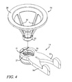
- FIG. 4 is a perspective illustration of a lens cone, interfacing with a gripper/interface structure, and incorporating an applanation lens in accordance with the invention
- FIG. 5 is a simplified, cross-sectional illustration of an attachment ring, suitable for use in connection with the ocular stabilization and applanation device of FIG. 1 ;
- FIG. 6 is a simplified, cross-sectional illustration of the attachment ring of FIG. 5 , illustrating the coupling of the attachment ring to the anterior surface of a patient's eye, and indicating applanation of the corneal surface;
- FIG. 7 is a simplified, cross-sectional illustration of a first embodiment of an applanation lens disposed within an attachment ring;
- FIG. 8 is a simplified cross-sectional illustration of the ocular stabilization and applanation device of FIG. 1 , showing operation of the device to applanate the corneal surface of an eye.
- FIG. 9 is a simplified, cross-sectional illustration of a second embodiment of an applanation lens disposed within an attachment ring;
- FIG. 10 is a simplified, semi-schematic illustration of the top surface of a gripper/interface device and showing radial alignment guides, in accordance with the present invention.
- the present invention is directed to a mechanical apparatus that performs the functions of coupling the anterior surface of a target eye to a surgical laser and applanating said eye.
- the apparatus is termed mechanical because it directly couples the mechanical surface of an operative target, such as human corneal tissue, to a mechanical fixture of a surgical laser system, such as the distal tip of a laser beam's delivery system.
- an operative target such as human corneal tissue
- a mechanical fixture of a surgical laser system such as the distal tip of a laser beam's delivery system.
- an illustrative ocular fixation and applanation device is shown in an exploded, perspective view, and is generally indicated at 10 .
- the ocular fixation and applanation device (referred to herein as simply an applanation device or alternatively, a patient interface) is an apparatus that attaches to a human eye and holds (fixes) the eye in all three axes (x, y and z) from translational and rotational movement with respect to the incident beam of a laser surgical device.
- the applanation device allows for the cornea of the eye to be applanated by a lens (laser optic) for efficient ophthalmic surgery.
- the applanation device grips, holds or affixes the eye to the applanation lens, or laser optic, during a laser surgical procedure, so as to minimize or preclude differential motion of the human eye with respect to the laser optical path during the laser procedure.
- the applanation device 10 is comprised of a number of component parts that may be disposable (i.e., used once and discarded) and/or re-usable.
- the applanation device 10 suitably comprises an ocular attachment ring 12 , by means of which the applanation device 10 is coupled to the eye, a gripper fixture 14 , a lens cone fixture 16 and an applanation lens 18 , which in combination with the lens cone 16 is used to applanate a patient's cornea and establish an appropriate optical path alignment between the cornea and a laser optical path.
- the component parts of the applanation device 10 are illustrated in exploded view, and are intended to be collapsed vertically, such that each of the individual portions of the device are in mechanical engagement with appropriate other portions, such that the completed device is provided in a generally unitary structure.
- the devices' component parts are permanently affixed to one another: indeed, the component parts are separable and interchangeable at will.
- the applanation device 10 is intended to form a single composite interface structure between a human cornea and a surgical laser once the component parts have been aligned with a patient's eye and with respect to the laser delivery system, as will be described in detail below.
- the attachment ring 12 forms the mechanical interface between the anterior surface of a human cornea and the remaining structure of the applanation device.
- the attachment ring 12 is constructed of a flexible, hypoallergenic material such as rubber, hypoallergenic plastic, silicone, or the like.
- the attachment ring 12 is substantially annular in shape, having a generally smooth exterior surface and a highly articulated and functional inner surface, as will be described in greater detail below. Being annular in shape, the attachment ring 12 necessarily defines an outer diameter (OD) and inner diameter (ID), with the inner diameter circumscribing a central target opening 13 .
- the absolute value of its outer diameter is not particularly relevant to practice the principles of the present invention, but the value of the inner diameter is suitably chosen such that when the attachment ring 12 is placed over a patient's eye, the attachment ring's central opening, defined by the inner diameter, completely circumscribes a sufficient area of corneal tissue such that a surgical laser procedure may be completely performed within the exposed area without having to displace the attachment ring.
- the attachment ring 12 is disposed and retained within an appropriately shaped female-type receptacle provided in the underside of the gripper/interface structure 14 . Since the attachment ring 12 is constructed of a flexible material, the female receptacle of the gripper structure 14 need only have an ID of a dimension slightly smaller than the OD of the attachment ring, such that the attachment ring may fit within the receptacle and be held in place by compressive force.
- the gripper/interface structure 14 of the exemplary embodiment of FIG. 1 is detailed in the top plan view illustration of FIG. 2 and the side view illustration of FIG. 3 .
- the gripper/interface 14 functions much like a clothes pin, and is constructed with a gripper portion 19 , overlaying a receiver portion 20 that is designed to receive and contain the attachment ring 12 within a central opening 21 that passes through both the gripper portion and the receiver portion.
- the gripper portion 19 is constructed as a lever, characterized by two lever handles 22 and 24 separated by a closure spacing 25 . As the lever handles are squeezed together, the closure spacing 25 closes and a deformation force is transmitted to two jaws 26 and 27 surrounding the central opening 21 .
- the receiver portion 20 is disposed below the jaws of the gripper portion and lays in a plane parallel to that of the gripper portion.
- the receiver portion is cantilevered forward from the space between the lever handles and the jaws and is separated from the gripper jaws by a slight spacing.
- the receiver portion is substantially annular in shape with the central opening 21 extending therethrough.
- attachment ring 12 allows the attachment ring 12 to be maintained within the central opening portion of the receiving portion, when the gripper jaws are opened.
- the gripper jaws may be opened to receive, for example, the lens cone, without disturbing or displacing the attachment ring.
- the lens cone fixture 16 is suitably constructed as an open-sided truncated cone-like structure, with an open, annular base ring 28 affixed to an open, cylindrical apex ring 30 by a set of support struts 32 which extend between the base ring 28 and the apex ring 30 .
- the base ring 28 is larger than the apex ring 30 thereby giving the lens cone 16 its characteristic truncated cone-like shape.
- the apex ring 30 will be understood to comprise an inner diameter (ID) and an outer diameter (OD), wherein the OD is dimensioned such that it is only slightly larger than the ID of the central opening portion 21 of the gripper portion 19 of the gripper/interface structure 14 .
- the lens cone structure 16 is constructed of a substantially rigid material such as a rigid, extruded plastic, aluminum, or the like, such that the OD of the apex ring 30 would not be expected to substantially deform under pressure, particularly not under the compression forces applied by the jaws of the gripper.
- the lens cone fixture 16 would not precisely fit into the ID of the central opening 21 of the gripper/interface structure 14 under normal circumstances.
- that force is applied to the remainder of the structure, causing the jaws 26 and 27 to open and the interior diameter of central opening 21 to increase in consequence.
- the OD of the apex ring 30 of the lens cone structure 16 is able to then be inserted into the central opening 21 of the gripper/interface structure 14 and, when pressure is released on the lever handles 22 and 24 , the jaws 26 and 27 close upon the apex ring 30 thereby grasping the apex ring and establishing a fixed relationship between the lens cone 16 and the gripper/interface structure 14 .
- the gripper/interface structure 14 is in geometric engagement with the attachment ring 12 , and since the attachment ring 12 is coupled to corneal tissue, it should be understood that the lens cone fixture 16 is now held in a particular spatial relationship (alignment) with the surface of the cornea.
- the apex ring 30 defines a receptacle for receiving and retaining an applanation lens 18 . It is the intention of the invention to place the applanation lens 18 in proximate contact with a human cornea, and since it is the function of the attachment ring 12 to mechanically interface with a human eye, it should be understood that the gripper/interface structure 14 functions to provide an alignment and coupling interface between the lens cone fixture, including the applanation lens 18 , and the attachment ring 12 , and thereby the patient's eye.
- the base ring portion 28 of the lens cone fixture 16 is adapted to be affixed to the distal end of a laser optical delivery system, such that the delivery system need only be concerned with focusing an incident laser beam at a particular point in space.
- the surface of the applanation lens in contact with corneal tissue (the applanation surface) is disposed at a specific distance from the interface between the base ring and the laser delivery system, such that the anterior corneal surface, or at least that portion in contact with the applanation lens, is at a known specific distance from the laser delivery tip.
- the surface of the cornea now resides along a plane at a distance known to the laser.
- FIG. 5 illustrates the attachment ring alone
- FIG. 6 illustrates the attachment ring as it would be applied to the anterior surface of a patient's eye.
- the attachment ring 12 it is the function of the attachment ring 12 to provide a primary interface with an operative target, such as a human eye, and a laser delivery system.
- the operative target is represented as the corneal portion 34 a of a human eye 34 in the exemplary embodiment of FIG. 6 , and to which the attachment ring 12 is illustrated as being affixed.
- FIG. 6 illustrates the corneal portion 34 a of a human eye 34
- the attachment ring 12 is illustrated as having an interior and exterior portion, the exterior portion of which is characterized by a lower skirt 36 which functions as a shroud that comes into intimate contact with the anterior portion of the human eye 34 .
- the shroud 36 has a relatively thin cross-section and is deformable so as to establish and maintain conformal contact with the anterior corneal surface.
- the shroud or skirt portion 36 extends upwardly into a crown surface 38 which maintains a substantially uniform ID against deformations of the lower shroud portion 36 in response to pressure against the shroud portion by the human eye.
- the attachment ring 12 further includes an interior, annular ring member 40 which is disposed on and protrudes outwardly from the interior surface of the attachment ring.
- the annular ring member 40 protrudes outwardly in a direction normal to the interior surface of the attachment ring, on its top surface, but is formed with a bottom surface that includes an upwardly extending cavity 42 , with the cavity formed between a bottom portion of the annular ring member 40 and a proximate portion of the interior surface of the attachment ring 12 .
- the cavity 42 formed by the shape of the annular ring member 40 defines an annular cavity, with its opening pointing towards the bottom, shroud or skirt portion of the attachment ring.
- the attachment ring 12 further includes an attachment fitting 44 which extends, in a radial direction, from the exterior surface of the attachment ring.
- the attachment fitting 44 includes a central orifice 46 , disposed along its entire length, and which passes through the material of the attachment ring's skirt portion 36 , such that a communication path is opened between the annular channel 42 , at one end, and the distal end of the attachment fitting 44 .
- the attachment fitting 44 might be constructed of the same material as the attachment ring, indeed the entire apparatus might be formed or molded as single piece.
- the attachment fitting 44 might be a separate small piece of plastic, metal, or some other material that is coupled to the attachment ring 12 at any stage in the manufacturing or assembly process of the applanation device 10 .
- the attachment fitting 44 were to be constructed from the same pliant, flexible rubber, silicone or plastic material as the attachment ring, a suitable female receptacle can be provided on the underside of the gripper structure 14 in proximity to and extending from the central opening 21 thereof.
- the attachment fixture 44 is also press-fit into its corresponding female receptacle, thereby orienting and retaining the entire attachment ring structure within the gripper 14 , by compressive force.
- attachment fixture 44 might be accessed by inserting one side of a male-to-male fitting coupler 45 ( FIG. 1 ) into the central orifice 46 and coupling the other side to a length of small diameter, medical grade tubing.
- the tubing is then coupled to a vacuum source which, in turn, is then able to apply a vacuum to the annular channel 42 through the attachment fixture 44 .
- attachment ring 12 may be configured with projections, such as “teeth”, “bumps”, or some such other gripping or friction inducing structure, that would serve to attach the attachment ring to the eye without the need for suction.
- the ocular attachment ring 12 is placed around the limbus of a patient's eye 34 , such that its lower, skirt portion 36 surrounds the anterior surface of the cornea 34 a , thereby leaving free optical access to the cornea 34 a .
- a slight compressive force is applied to the attachment ring, thereby deforming the skirt portion 36 in an outwardly direction, such that it tends to conform to the shape of the corneal surface.
- a slight vacuum is developed by a vacuum source or suction pump and coupled to the attachment ring through the attachment fitting 44 .
- the attachment fitting 44 As suction is applied to the attachment fitting 44 , its internal orifice 46 couples the suction to the annular channel 42 which is now sealed-off from the external ambient environment by corneal contact with the skirt portion 36 (forming one side of the channel) and a contact edge 50 of the annular ring member 40 (forming the other surface of the channel). A vacuum is thereby developed within the annular channel 42 which, in turn, couples the attachment ring 12 to the corneal surface 34 a , thereby fixing the eye to the attachment ring which, when it is itself coupled to the rest of the structure, as will be described in greater detail below, fixes the eye against relative movement.
- the attachment ring 12 is affixed to the gripper structure 14 , prior to the attachment ring's being coupled to an eye.
- the gripper is not shown as being already attached to the attachment ring in order that the particular structural and functional details of the attachment ring may be shown simply and without regard to additional and potentially confusing structure.
- two corneal surface shapes are depicted in the illustrated embodiment of FIG. 6 , a rounded surface 34 a , indicating the normal shape of the cornea, and a flattened surface 34 b indicating the effects of applanating the corneal surface.
- the gripper/ring structure is affixed to the eye 34 , the structure surrounds the limbus, leaving the corneal area open to access.
- the corneal surface remains substantially rounded, at this point, and is only contoured or flattened after introduction of the applanation cone 16 into the gripper and contact is made between the applanation lens 18 and the cornea 34 a .
- the applanated corneal surface 34 b then takes on a shape imposed by the shape of the contact surface (applanation surface) of the applanation lens.
- the vacuum or suction developed by the vacuum source or suction pump is transmitted to the attachment fitting 44 by small-bore tubing.
- the suction might be applied by coupling the tip of a syringe to the attachment fitting 44 and by introducing a vacuum in the body of the syringe. That vacuum is transmitted to the attachment ring by a small-bore tubing, a blunt canula, or the like. All that is required is that a vacuum (partial or otherwise) be formed within the annular channel 42 such that it is able to provide a coupling force between the attachment ring and the corneal surface.
- the lens cone 16 affords similar functionality to the attachment ring 12 , in that the lens cone 16 provides the primary interface and attachment between the applanation device ( 10 of FIG. 1 ) and the delivery tip of a surgical laser system.
- the base ring 28 is rigidly coupled to the laser delivery system. Attachment between the two structures may be made in a number of ways, while remaining within the scope of the invention.
- the base ring 28 may be provided with slot-shaped cutouts which are mated with retaining pins provided on the delivery system, with the base ring being inserted over the pins and rotated in order to create an interlock.
- the base ring can be screwed into place on the delivery tip or, the delivery tip might be provided with rotatable “dogs” which are rotated into place over the base ring 28 thereby securing the base ring into position.
- the means by which the base ring and thus the lens cone 16 are affixed to the delivery tip is not particularly material to practice the principals of the invention. All that is required is that the lens cone 16 be affixed to the delivery tip such that it is incapable of independent relative movement with respect to the delivery tip.
- the base ring has a top surface defining a generally horizontal plane (an x, y plane).
- the delivery tip is provided with a similar planar surface which is mated with the planar base ring surface. An x, y plane defining one aspect of ocular applanation is thereby established.
- the lens cone's apex ring 30 extends downwardly away from the base ring 28 and is held in a particular spatial relationship by struts 32 , extending between the apex ring 30 and the base ring 28 .
- the base ring 30 is a substantially cylindrical structure with outer and inner wall surfaces and with a wall thickness sufficient to support reasonable rigidity under compressive stress.
- An applanation lens 18 is disposed within the apex ring 30 and has an OD substantially the same as the ID of the apex ring such that it fits into the apex ring and rests against the ring's interior wall surface.
- the applanation lens 18 is then bonded into place forming a generally unitary structure with the lens cone 16 .
- the applanation lens 18 is formed with an anterior surface 64 and an applanation surface 66 . It is to be appreciated that both the anterior surface 64 and the applanation surface 66 are substantially flat and substantially parallel to one another.
- the applanation lens 18 is suitably constructed from a quartz silicate glass or an optical quality plastic chosen for its transmission characteristics of light at the particular wavelength delivered by the laser system under consideration.
- Manufacture of the lens cone involves bonding and alignment of the applanation lens 18 to the apex ring 30 . Both of these operations (bonding and alignment) are performed at substantially the same time.
- the lens cone 16 is placed in registration with an alignment and bonding fixture, termed a “golden pedestal”.
- the golden pedestal has a horizontal alignment plane (an x, y plane) which is positioned parallel to the x, y plane defining the base ring 28 .
- An applanation lens 18 is positioned on the golden pedestal such that its parallel anterior and applanation surfaces lie in the x, y plane defined by the pedestal and, thus the base ring.
- the lens cone is lowered over the lens until the lens is positioned within the apex ring portion, all the while maintaining the relationship between the various x, y planes.
- a suitable glue such as a UV curing cement
- the applanation lens is established in a specific x, y plane and at a specific z distance from the base ring, itself established in a specific x, y plane and at a specific z distance from the delivery tip of a surgical laser.
- a known spatial relationship between the laser and the applanation surface of the applanation lens is thereby defined.
- the lower, contact, or applanation, surface of the applanation lens is disposed in space in a particular relationship with the laser delivery tip.
- the contact surface provides a reference surface from which the laser system is able to compute a depth of focus characteristic. Since the position of the contact surface is known, with respect to the delivery tip, so too is the position of the applanated corneal surface. It is, therefore, a relatively straightforward matter to focus a laser beam to any point within the cornea. One needs only to calculate the focal point with respect to the contact surface of the lens, in order that the same focal point be obtained within the eye.
- Aligning the lens into position with respect to the lens cone structure by use of a “golden pedestal” allows alignment tolerances which are substantially tighter than those currently obtainable by conventional microkeratome techniques.
- Conventional microkeratomes typically exhibit off-plane errors in the range of about +/ ⁇ 30 to +/ ⁇ 40 microns. This alignment error leads to planar tilt in the corneal flap, and to potentially dangerous flap thickness variations. For example, if a flap were created with a 30 to 40 micron error, in the positive thickness direction, there exists the possibility that the remaining corneal bed would not be sufficiently thick to safely conduct a laser ablation procedure. Instead the cornea would tend to bulge outward, in response, leading to a less than optimum surface shape being presented for subsequent laser surface ablation. Indeed, it is the very scale of microkeratome depth uncertainty that contributes to the significant percentage of conventional laser surgery failures.
- the “golden pedestal” registration and alignment system allows for planar (in both the x, y plane and the z direction) alignment tolerances no greater than that of a conventional microkeratome, i.e., in the range of about +/ ⁇ 30 microns, and preferably in the range of about +/ ⁇ 10 microns. This is measured with respect to both the planar “tilt” and the z position of the applanation surface of the applanation lens with respect to the defined plane of the base ring and, therefore, with respect to the laser's delivery tip.
- the applanation surface is devised to be co-planar with the anterior surface of the cornea, thereby defining a corneal surface which is mathematically calculable and precise with respect to the laser delivery tip: the x,y plane of the corneal surface is known and the z distance from the tip to the surface is also known.
- a precise cut may be made within the corneal material without concern for potentially dangerous depth variation.
- FIG. 8 an exemplary embodiment of the complete ocular fixation device 10 , as it would be attached to a human eye, is illustrated in cross-sectional form.
- the lens cone 16 is coupled to the attachment ring 12 , thereby coupling a patient's eye 34 to the laser delivery system, by interfacing the two structures together by the gripper/interface 14 .
- the apex ring 30 has an OD sized just slightly larger than the ID of the gripper's annular mating portion 20 , such that the apex ring 30 can be inserted into the central opening 21 of the gripper 14 , when the jaws of the gripper are opened.
- the apex ring is inserted into the central opening, pressure released on the gripping structures 22 and 24 thereby allowing the jaws to relax and to close around and grip the apex ring 30 securely within the gripper's central opening.
- the applanation surface of the applanation lens makes contact with a presented portion of the anterior surface of the cornea 34 b .
- the applanation surface of the lens makes contact with the cornea and applies a pressure to the cornea such that when the lens cone is fully lowered into position, the corneal anterior surface 34 b and the applanation surface 66 of the lens are in intimate contact with one another over a substantial portion of the applanation surface.
- the corneal surface to conform to the shape of the applanation surface of the lens.
- the cornea may be formed as a concave or convex surface, depending only on the shape of the contact surface of the applanation lens.
- the attachment ring 12 is placed around the limbus of the eye, i.e., centered about the cornea and the pupillary aperture.
- the gripper 14 has been previously affixed to the attachment ring 12 , such that positioning the ring with respect to the eye also positions the eye with respect to the gripper's central opening, with the pupillary aperture generally centered within the gripper's opening. Suction is then applied to the ring in order to attach the ring onto the eye.
- the attachment ring 12 With the eye so presented and held in place by the attachment ring 12 , it becomes a relatively simple matter to lower the lens cone and applanation lens into proximate contact with the cornea, and retain the lens cone, and particularly the applanation lens, in position by fixing the apex ring with the gripper.
- the gripper is opened to receive the cone assembly which is then lowered into the attachment ring. Simultaneously, the contact surface (applanation surface) of the lens contacts the corneal surface thereby applanating the cornea.
- the gripper is then closed, thereby clamping the cone assembly in position and fixing the lens relative to the applanated cornea.
- the eye is held to the gripper by the attachment ring, while the applanation lens is held to the eye by the gripper.
- the applanation device is substantially rigidly coupled to the laser delivery system, thus the plane of the applanation surface 66 is characterizable in space with respect to any given focal point of an incident laser beam.
- the applanation lens 18 is able to “float” in the “z” direction due to the flexibility of the skirt portion of the attachment ring.
- the applanation lens 18 is therefore able to accommodate variously shaped corneal surfaces without placing undue pressure on the eye.
- the applanation lens 18 is secured against lateral motion and is accurately disposed in a stable “x,y” plane with respect to the eye.
- the applanation lens need not be affixed to the apex ring by a “golden pedestal” approach.
- sufficient alignment of the lens 18 to the plane of the base ring 28 can be accomplished by machining the apex ring 30 to include a retaining lip 31 disposed around the bottom edge of the apex ring.
- the applanation lens is inserted into the apex ring from the top, and allowed to rest against the retaining lip 31 .
- the lens is now bonded into position using a suitable glue, such as a UV curing cement.
- the retaining lip 31 might be provided as an annular structure circumscribing the interior wall of the apex ring.
- the lens is inserted from the bottom until its anterior surface rests against the interior lip, at which position it is bonded into place. All that is required in any retaining embodiment, is that the lens be positioned with respect to the lens cone structure such that its alignment in the x, y plane and in the z direction is at least within an approximately +/ ⁇ 30 micron range. In other words, the applanation surface (and therefore the surface of the eye) must be mathematically definable with regard to a laser delivery system to within about +/ ⁇ 30 microns.
- the lens might not be affixed to the lens cone structure prior to the device being assembled on a patient's eye.
- the applanation lens might be provided as a separate component from the lens cone structure.
- the applanation lens is constructed as a shallow dish, with sides extending vertically upwards and having an OD such that it may be press-fit within the interior of the annular attachment ring. As the attachment ring and applanation lens combination is fixed to the corneal surface, the applanation lens is able to partially applanate the corneal surface in order to improve alignment.
- the attachment ring may or may not be fitted within its appropriate receptacle in the gripper structure.
- the attachment ring either with or without the applanation lens included, might be first affixed on the patient's eye and the gripper structure lowered over the attachment ring, or, alternatively, the attachment ring, either with or without the applanation lens included, is press fit into its appropriate receptacle on the gripper structure and the entire composite placed over the surface of the patient's eye. In this particular instance, care must be taken to precisely manufacture the bottom surface of the apex ring, since this is the portion of the lens cone which now contacts the applanation lens.
- the lens cone is lowered into position into the central opening of the gripper and the jaws of the gripper are allowed to relax, thereby grasping and retaining the lens cone in position.
- final applanation takes place as the applanation lens is either further pressurized against the corneal surface by movement of the lens cone (if the lens is provided as a separate structure) or as the lens is moved into contact with the corneal surface, allowing cone pressure to applanate (if the lens is provided within the lens cone's apex ring).
- ocular pressure developed by the applanation process will not exceed approximately 60 mmHg, and will preferably be in the range of about 40 to 50 mm Hg.
- the lens cone might be secured to the gripper in a number of ways, in addition to being gripped by compressive jaws.
- the attachment ring might have a communication channel provided between the suction chamber and its interior surface. Accordingly, as the apex ring of the lens cone is lowered into engagement with the attachment ring, a suction is established between the attachment ring and the lens cone's apex ring thereby securing the lens cone to the attachment ring.
- suction involves a relatively simple application of force between the lens cone and attachment ring
- suction or vacuum
- the upper portion of the attachment ring might be provided with thin, magnetic material that attracts the lens cone's apex ring and provides for secured docking of the lens cone within the attachment ring.
- the gripper might be provided with a suction manifold disposed around the central opening and the apex ring provided with a flange that overlays manifold openings. As the lens cone is lowered into position, and the flange covers the manifold openings, suction is applied thereby securing the lens cone to the gripper structure.
- the present invention has been described, above, primarily with regard to aligning of the structure in relation to a human eye in the “z” dimension, while retaining the eye against relative motion along an “x, y” plane. It is also desirable to ensure proper alignment of the structure with regard to the central access of the eye, i.e., allow the structure to centrate about the pupil, such that the iris/pupil is positioned substantially in the center of the central opening of the attachment ring.
- the top surface of the gripper 14 (top being the surface opposite that in proximity with the eye) is provided with a set of alignment marks, or fiduciaries, radially disposed about the gripper's central opening 21 , on the upper surface of each jaw 26 and 27 and surrounding the central opening 21 .
- the fiduciaries are radially disposed and, if extended towards the center of the opening, aligned such that they will cross at the opening centrum or axis.
- the alignment marks allow a clinician to judge the central placement of an eye in relation to the opening and eases the clinician's task in accurately positioning the attachment ring/gripper structure with respect to the ocular centrum, before the lens cone is lowered into position for applanation.
- the already aligned gripper laterally aligns the lens, in turn, to the eye. If the structure is appropriately aligned such that the eye is substantially centered within the central opening, a nominal relationship will be established between a laser delivery system and the structural features of an eye in all directions (i.e., x, y, z). This simple mechanical approach obviates the need for complex, highly sophisticated eye following and tracking mechanisms.
- any appropriate laser medium might be used to deliver the incident laser beam without regard to the particular form and shape of the delivery system.
- the gripper structure need not be a unitary structure, for example, but may indeed be hinged in a central portion and the gripper jaws opened and closed in response to spring tension and compression made between the gripper handles.
- the applanation lens need not be provided with a substantially flat applanation surface. Depending on the ophthalmic procedure intended to be carried out by the laser system, the lens's applanation surface may be concave or convex in accordance with an appropriate mathematically derived curvature, without departing from the scope and spirit of the invention.
Abstract
Description
Claims (20)
Priority Applications (7)
| Application Number | Priority Date | Filing Date | Title |
|---|---|---|---|
| US09/772,539 US6863667B2 (en) | 2001-01-29 | 2001-01-29 | Ocular fixation and stabilization device for ophthalmic surgical applications |
| US09/896,429 US6899707B2 (en) | 2001-01-29 | 2001-06-29 | Applanation lens and method for ophthalmic surgical applications |
| US10/865,165 US7018376B2 (en) | 2001-01-29 | 2004-06-10 | Ocular fixation and stabilization device for ophthalmic surgical applications |
| US11/277,477 US7371230B2 (en) | 2001-01-29 | 2006-03-24 | Ocular fixation and stabilization device for ophthalmic surgical applications |
| US11/948,433 US20080071254A1 (en) | 2001-01-29 | 2007-11-30 | Ophthalmic interface apparatus and system and method of interfacing a surgical laser with an eye |
| US13/230,590 US20120016349A1 (en) | 2001-01-29 | 2011-09-12 | Hybrid ophthalmic interface apparatus and method of interfacing a surgical laser with an eye |
| US13/649,849 US8568394B2 (en) | 2001-01-29 | 2012-10-11 | Ophthalmic interface apparatus and system and method of interfacing a surgical laser with an eye |
Applications Claiming Priority (1)
| Application Number | Priority Date | Filing Date | Title |
|---|---|---|---|
| US09/772,539 US6863667B2 (en) | 2001-01-29 | 2001-01-29 | Ocular fixation and stabilization device for ophthalmic surgical applications |
Related Child Applications (2)
| Application Number | Title | Priority Date | Filing Date |
|---|---|---|---|
| US09/896,429 Continuation-In-Part US6899707B2 (en) | 2001-01-29 | 2001-06-29 | Applanation lens and method for ophthalmic surgical applications |
| US10/865,165 Division US7018376B2 (en) | 2001-01-29 | 2004-06-10 | Ocular fixation and stabilization device for ophthalmic surgical applications |
Publications (2)
| Publication Number | Publication Date |
|---|---|
| US20020103481A1 US20020103481A1 (en) | 2002-08-01 |
| US6863667B2 true US6863667B2 (en) | 2005-03-08 |
Family
ID=25095410
Family Applications (3)
| Application Number | Title | Priority Date | Filing Date |
|---|---|---|---|
| US09/772,539 Expired - Lifetime US6863667B2 (en) | 2001-01-29 | 2001-01-29 | Ocular fixation and stabilization device for ophthalmic surgical applications |
| US10/865,165 Expired - Lifetime US7018376B2 (en) | 2001-01-29 | 2004-06-10 | Ocular fixation and stabilization device for ophthalmic surgical applications |
| US11/277,477 Expired - Lifetime US7371230B2 (en) | 2001-01-29 | 2006-03-24 | Ocular fixation and stabilization device for ophthalmic surgical applications |
Family Applications After (2)
| Application Number | Title | Priority Date | Filing Date |
|---|---|---|---|
| US10/865,165 Expired - Lifetime US7018376B2 (en) | 2001-01-29 | 2004-06-10 | Ocular fixation and stabilization device for ophthalmic surgical applications |
| US11/277,477 Expired - Lifetime US7371230B2 (en) | 2001-01-29 | 2006-03-24 | Ocular fixation and stabilization device for ophthalmic surgical applications |
Country Status (1)
| Country | Link |
|---|---|
| US (3) | US6863667B2 (en) |
Cited By (84)
| Publication number | Priority date | Publication date | Assignee | Title |
|---|---|---|---|---|
| US20040225284A1 (en) * | 2001-01-29 | 2004-11-11 | Webb R. Kyle | Ocular fixation and stabilization device for ophthalmic surgical applications |
| US20050143718A1 (en) * | 2004-12-02 | 2005-06-30 | Sie Ag Surgical Instrument Engineering | Method for surgical treatment of a patient's eye by means of a laser |
| US20070093796A1 (en) * | 2005-10-24 | 2007-04-26 | Intralase Corp. | Disposable patient interface |
| US20070093795A1 (en) * | 2005-10-21 | 2007-04-26 | Markus Melcher | Cornea contact system |
| US20070173794A1 (en) * | 2006-01-20 | 2007-07-26 | Frey Rudolph W | System and method for treating the structure of the human lens with a laser |
| US20070185475A1 (en) * | 2006-01-20 | 2007-08-09 | Frey Rudolph W | System and method for providing the shaped structural weakening of the human lens with a laser |
| US20080058841A1 (en) * | 2006-09-05 | 2008-03-06 | Kurtz Ronald M | System and method for marking corneal tissue in a transplant procedure |
| US20080058777A1 (en) * | 2006-09-05 | 2008-03-06 | Intralase Corp. | System and method for resecting corneal tissue using non-continuous initial incisions |
| WO2008030698A2 (en) | 2006-09-05 | 2008-03-13 | Amo Development, Llc | System and method for resecting corneal tissue |
| US20080091224A1 (en) * | 2006-07-11 | 2008-04-17 | Refocus Group, Inc. | Apparatus and method for securing ocular tissue |
| US20080089481A1 (en) * | 2006-10-16 | 2008-04-17 | Oraya Therapeutics, Inc. | Portable orthovoltage radiotherapy |
| US20080212738A1 (en) * | 2006-12-13 | 2008-09-04 | Oraya Therapeutics, Inc. | Orthovoltage radiotherapy |
| US20080287927A1 (en) * | 2004-12-02 | 2008-11-20 | Sie Ag Surgical Instrument Engineering | Protective device for ophthalmic laser treatment |
| US20090069794A1 (en) * | 2007-09-10 | 2009-03-12 | Kurtz Ronald M | Apparatus, Systems And Techniques For Interfacing With An Eye In Laser Surgery |
| US20090131921A1 (en) * | 2007-09-06 | 2009-05-21 | Lensx Lasers, Inc. | Precise Targeting of Surgical Photodisruption |
| US20090137988A1 (en) * | 2007-11-02 | 2009-05-28 | Lensx Lasers, Inc | Methods And Apparatus For Improved Post-Operative Ocular Optical Performance |
| US20090137993A1 (en) * | 2007-09-18 | 2009-05-28 | Kurtz Ronald M | Methods and Apparatus for Integrated Cataract Surgery |
| US20090137991A1 (en) * | 2007-09-18 | 2009-05-28 | Kurtz Ronald M | Methods and Apparatus for Laser Treatment of the Crystalline Lens |
| US20090143772A1 (en) * | 2007-09-05 | 2009-06-04 | Kurtz Ronald M | Laser-Induced Protection Shield in Laser Surgery |
| US20090149840A1 (en) * | 2007-09-06 | 2009-06-11 | Kurtz Ronald M | Photodisruptive Treatment of Crystalline Lens |
| US20090149841A1 (en) * | 2007-09-10 | 2009-06-11 | Kurtz Ronald M | Effective Laser Photodisruptive Surgery in a Gravity Field |
| US20090161827A1 (en) * | 2007-12-23 | 2009-06-25 | Oraya Therapeutics, Inc. | Methods and devices for detecting, controlling, and predicting radiation delivery |
| US20090161826A1 (en) * | 2007-12-23 | 2009-06-25 | Oraya Therapeutics, Inc. | Methods and devices for orthovoltage ocular radiotherapy and treatment planning |
| US20090163898A1 (en) * | 2007-06-04 | 2009-06-25 | Oraya Therapeutics, Inc. | Method and device for ocular alignment and coupling of ocular structures |
| US20090171327A1 (en) * | 2007-09-06 | 2009-07-02 | Lensx Lasers, Inc. | Photodisruptive Laser Treatment of the Crystalline Lens |
| US20090177189A1 (en) * | 2008-01-09 | 2009-07-09 | Ferenc Raksi | Photodisruptive laser fragmentation of tissue |
| US20090182311A1 (en) * | 2008-01-11 | 2009-07-16 | Oraya Therapeutics, Inc. | System and method for positioning and stabilizing an eye |
| US20090234335A1 (en) * | 2006-03-17 | 2009-09-17 | Amo Manufacturing Usa, Llc | Intrastromal refractive correction systems and methods |
| US20100004641A1 (en) * | 2006-01-20 | 2010-01-07 | Frey Rudolph W | System and apparatus for delivering a laser beam to the lens of an eye |
| US20100022994A1 (en) * | 2008-07-25 | 2010-01-28 | Frey Rudolph W | Liquid filled index matching device for ophthalmic laser procedures |
| US20100042079A1 (en) * | 2008-07-25 | 2010-02-18 | Frey Rudolph W | Method and System for Removal and Replacement of Lens Material fron the Lens of an Eye |
| US20100130966A1 (en) * | 2008-11-21 | 2010-05-27 | Advanced Medical Optics, Inc. | Apparatus, System and Method for Precision Depth Measurement |
| US20110190741A1 (en) * | 2008-08-25 | 2011-08-04 | Thomas Deisinger | Coupling of an eye to a laser device |
| US20110202044A1 (en) * | 2010-02-18 | 2011-08-18 | Ilya Goldshleger | Optical Coherence Tomographic System for Ophthalmic Surgery |
| US20120016349A1 (en) * | 2001-01-29 | 2012-01-19 | Amo Development, Llc. | Hybrid ophthalmic interface apparatus and method of interfacing a surgical laser with an eye |
| US8265364B2 (en) | 2010-02-05 | 2012-09-11 | Alcon Lensx, Inc. | Gradient search integrated with local imaging in laser surgical systems |
| US8382745B2 (en) | 2009-07-24 | 2013-02-26 | Lensar, Inc. | Laser system and method for astigmatic corrections in association with cataract treatment |
| US8398238B1 (en) | 2011-08-26 | 2013-03-19 | Alcon Lensx, Inc. | Imaging-based guidance system for ophthalmic docking using a location-orientation analysis |
| US8398236B2 (en) | 2010-06-14 | 2013-03-19 | Alcon Lensx, Inc. | Image-guided docking for ophthalmic surgical systems |
| US20130090634A1 (en) * | 2011-10-06 | 2013-04-11 | James Carlton Loden | Corneal incision using a surgical laser |
| US8459794B2 (en) | 2011-05-02 | 2013-06-11 | Alcon Lensx, Inc. | Image-processor-controlled misalignment-reduction for ophthalmic systems |
| US8465478B2 (en) | 2009-07-24 | 2013-06-18 | Lensar, Inc. | System and method for performing LADAR assisted procedures on the lens of an eye |
| US8556425B2 (en) | 2010-02-01 | 2013-10-15 | Lensar, Inc. | Purkinjie image-based alignment of suction ring in ophthalmic applications |
| US8568394B2 (en) | 2001-01-29 | 2013-10-29 | Amo Development Llc | Ophthalmic interface apparatus and system and method of interfacing a surgical laser with an eye |
| USD694890S1 (en) | 2010-10-15 | 2013-12-03 | Lensar, Inc. | Laser system for treatment of the eye |
| USD695408S1 (en) | 2010-10-15 | 2013-12-10 | Lensar, Inc. | Laser system for treatment of the eye |
| US8617146B2 (en) | 2009-07-24 | 2013-12-31 | Lensar, Inc. | Laser system and method for correction of induced astigmatism |
| US8758332B2 (en) | 2009-07-24 | 2014-06-24 | Lensar, Inc. | Laser system and method for performing and sealing corneal incisions in the eye |
| US8801186B2 (en) | 2010-10-15 | 2014-08-12 | Lensar, Inc. | System and method of scan controlled illumination of structures within an eye |
| US20140275751A1 (en) * | 2013-03-15 | 2014-09-18 | Abbott Medical Optics Inc. | Collagen-based ophthalmic interface for laser ophthalmic surgery |
| WO2014149774A2 (en) | 2013-03-15 | 2014-09-25 | Amo Development Llc. | System and method for ophthalmic laser surgery employing eye tracking without eye docking |
| WO2014149625A1 (en) | 2013-03-15 | 2014-09-25 | Amo Development Llc | Systems and methods for providing anatomical flap centration for an ophthalmic laser treatment system |
| US8845624B2 (en) | 2010-06-25 | 2014-09-30 | Alcon LexSx, Inc. | Adaptive patient interface |
| US8863749B2 (en) | 2011-10-21 | 2014-10-21 | Optimedica Corporation | Patient interface for ophthalmologic diagnostic and interventional procedures |
| US8939967B2 (en) | 2011-08-03 | 2015-01-27 | Alcon Lensx, Inc. | Patient interface defogger |
| US20150094805A1 (en) * | 2006-07-11 | 2015-04-02 | Refocus Group, Inc. | Scleral prosthesis for treating presbyopia and other eye disorders and related devices and methods |
| US9023016B2 (en) | 2011-12-19 | 2015-05-05 | Alcon Lensx, Inc. | Image processor for intra-surgical optical coherence tomographic imaging of laser cataract procedures |
| US9044302B2 (en) | 2011-10-21 | 2015-06-02 | Optimedica Corp. | Patient interface for ophthalmologic diagnostic and interventional procedures |
| US9044304B2 (en) | 2011-12-23 | 2015-06-02 | Alcon Lensx, Inc. | Patient interface with variable applanation |
| US9066784B2 (en) | 2011-12-19 | 2015-06-30 | Alcon Lensx, Inc. | Intra-surgical optical coherence tomographic imaging of cataract procedures |
| US9089401B2 (en) | 2011-05-06 | 2015-07-28 | Alcon Lensx, Inc. | Adjusting ophthalmic docking system |
| AU2013206830B2 (en) * | 2006-07-11 | 2015-09-24 | Refocus Group, Inc. | Scleral prosthesis for treating presbyopia and other eye disorders and related devices and methods |
| US9237967B2 (en) * | 2011-10-21 | 2016-01-19 | Optimedica Corporation | Patient interface for ophthalmologic diagnostic and interventional procedures |
| US9265458B2 (en) | 2012-12-04 | 2016-02-23 | Sync-Think, Inc. | Application of smooth pursuit cognitive testing paradigms to clinical drug development |
| US9351879B2 (en) | 2010-09-02 | 2016-05-31 | Optimedica Corporation | Patient interface for ophthalmologic diagnostic and interventional procedures |
| US9375349B2 (en) | 2006-01-20 | 2016-06-28 | Lensar, Llc | System and method for providing laser shot patterns to the lens of an eye |
| US9380976B2 (en) | 2013-03-11 | 2016-07-05 | Sync-Think, Inc. | Optical neuroinformatics |
| US9398979B2 (en) | 2013-03-11 | 2016-07-26 | Technolas Perfect Vision Gmbh | Dimensional compensator for use with a patient interface |
| AU2015264864B2 (en) * | 2006-07-11 | 2016-09-29 | Refocus Group, Inc. | Scleral prosthesis for treating presbyopia and other eye disorders and related devices and methods |
| US9492322B2 (en) | 2009-11-16 | 2016-11-15 | Alcon Lensx, Inc. | Imaging surgical target tissue by nonlinear scanning |
| US9532708B2 (en) | 2010-09-17 | 2017-01-03 | Alcon Lensx, Inc. | Electronically controlled fixation light for ophthalmic imaging systems |
| US9545338B2 (en) | 2006-01-20 | 2017-01-17 | Lensar, Llc. | System and method for improving the accommodative amplitude and increasing the refractive power of the human lens with a laser |
| US9603744B2 (en) | 2012-11-09 | 2017-03-28 | Technolas Perfect Vision Gmbh | Adaptable patient interface |
| US9622913B2 (en) | 2011-05-18 | 2017-04-18 | Alcon Lensx, Inc. | Imaging-controlled laser surgical system |
| US9724238B2 (en) | 2012-11-30 | 2017-08-08 | Amo Development, Llc | Ophthalmic interface apparatus, method of interfacing a surgical laser with an eye, and support ring for use with a suction ring |
| US10028654B2 (en) | 2013-03-15 | 2018-07-24 | Amo Development, Llc | System and method for eye orientation |
| WO2019079380A1 (en) | 2017-10-19 | 2019-04-25 | Amo Development, Llc | Medication-coated patient interface device for ophthalmic laser surgery |
| US10335315B2 (en) | 2013-02-01 | 2019-07-02 | Alcon Lensx, Inc. | Bi-radial patient interface |
| US10463541B2 (en) | 2011-03-25 | 2019-11-05 | Lensar, Inc. | System and method for correcting astigmatism using multiple paired arcuate laser generated corneal incisions |
| US10568764B2 (en) | 2013-03-14 | 2020-02-25 | Amo Development, Llc | System and methods for depth detection in laser-assisted ophthalmic procedures |
| RU2722976C2 (en) * | 2015-06-29 | 2020-06-05 | ЯНУНТС ХОЛДИНГ УГ (хафтунгсбешренкт) | Purkinje measurer and automatic evaluation method |
| US10799394B2 (en) | 2016-04-05 | 2020-10-13 | Amo Development, Llc | Patient interface device for laser eye surgery having light guiding structure for illuminating eye |
| WO2022238926A1 (en) | 2021-05-14 | 2022-11-17 | Amo Development, Llc | Patient interface device for ophthalmic surgical laser system |
| US11571333B2 (en) | 2020-05-18 | 2023-02-07 | Refocus Group, Inc. | Apparatus and method for securing ocular tissue and providing surgical tool positioning points |
Families Citing this family (71)
| Publication number | Priority date | Publication date | Assignee | Title |
|---|---|---|---|---|
| US9603741B2 (en) | 2000-05-19 | 2017-03-28 | Michael S. Berlin | Delivery system and method of use for the eye |
| US8679089B2 (en) | 2001-05-21 | 2014-03-25 | Michael S. Berlin | Glaucoma surgery methods and systems |
| ATE377404T1 (en) | 2000-05-19 | 2007-11-15 | Michael S Berlin | LASER APPLICATION SYSTEM AND METHOD FOR USE IN THE EYE |
| US6899707B2 (en) * | 2001-01-29 | 2005-05-31 | Intralase Corp. | Applanation lens and method for ophthalmic surgical applications |
| US6992765B2 (en) * | 2002-10-11 | 2006-01-31 | Intralase Corp. | Method and system for determining the alignment of a surface of a material in relation to a laser beam |
| US7556378B1 (en) * | 2003-04-10 | 2009-07-07 | Tsontcho Ianchulev | Intraoperative estimation of intraocular lens power |
| EP1486185B1 (en) | 2003-06-10 | 2006-09-27 | SIE AG, Surgical Instrument Engineering | Opthalmological device for ablation of eye tissue |
| DE10334110A1 (en) * | 2003-07-25 | 2005-02-17 | Carl Zeiss Meditec Ag | Apparatus and method for forming curved cut surfaces in a transparent material |
| DE10353264B4 (en) * | 2003-11-14 | 2022-07-07 | Carl Zeiss Meditec Ag | Adapter for coupling a laser processing device to an object |
| US7402159B2 (en) * | 2004-03-01 | 2008-07-22 | 20/10 Perfect Vision Optische Geraete Gmbh | System and method for positioning a patient for laser surgery |
| US7883505B2 (en) | 2004-04-20 | 2011-02-08 | Wavetec Vision Systems, Inc. | Integrated surgical microscope and wavefront sensor |
| DE102005001249A1 (en) * | 2005-01-11 | 2006-07-20 | Carl Zeiss Meditec Ag | Safety mechanism for a laser treatment device |
| US7189225B2 (en) * | 2005-05-09 | 2007-03-13 | Rosen Robert S | Device for conjunctival/scleral compression to constrict superficial blood flow and method of use |
| US7744614B2 (en) * | 2005-06-15 | 2010-06-29 | Krishna Imports, Incorporated | Corneal excision or scoring device |
| EP2277481B1 (en) | 2006-04-11 | 2013-04-03 | WaveLight GmbH | Laser arrangement for ophthalmic surgery |
| ES2367315T3 (en) * | 2006-07-04 | 2011-11-02 | Wavelight Gmbh | ELEMENT OF CONTACT WITH THE IMPROVED EYE. |
| KR101351863B1 (en) * | 2006-07-11 | 2014-01-15 | 리포쿠스 그룹 인코포레이티드 | Screral prosthesis for treating presbyopia and other eye disorders and related devices and methods |
| US7927344B2 (en) * | 2006-10-13 | 2011-04-19 | Burba Thomas A | Eye positioner |
| WO2008098206A1 (en) * | 2007-02-09 | 2008-08-14 | Altiva Corporation | Dynamic stabilization device |
| US20170360609A9 (en) | 2007-09-24 | 2017-12-21 | Ivantis, Inc. | Methods and devices for increasing aqueous humor outflow |
| US7594729B2 (en) | 2007-10-31 | 2009-09-29 | Wf Systems, Llc | Wavefront sensor |
| CA2717441A1 (en) | 2008-03-05 | 2009-09-11 | Ivantis, Inc. | Methods and apparatus for treating glaucoma |
| MX2010014009A (en) * | 2008-06-20 | 2011-05-03 | Walvelight Gmbh | Device for cutting a tissue part with focussed laser radiation. |
| WO2010054268A2 (en) | 2008-11-06 | 2010-05-14 | Wavetec Vision Systems, Inc. | Optical angular measurement system for ophthalmic applications and method for positioning of a toric intraocular lens with increased accuracy |
| US20130041354A1 (en) * | 2009-02-26 | 2013-02-14 | Amo Development, Llc. | Registering oct or other eye measurement system with a femtosecond flap cut or other laser surgical treatment using a common patient interface |
| US8641488B1 (en) * | 2009-06-18 | 2014-02-04 | Buffalo Filter Llc | Intake apparatus and system |
| US8876290B2 (en) | 2009-07-06 | 2014-11-04 | Wavetec Vision Systems, Inc. | Objective quality metric for ocular wavefront measurements |
| AU2010271218B2 (en) | 2009-07-09 | 2017-02-02 | Alcon Inc. | Ocular implants and methods for delivering ocular implants into the eye |
| CN102481171B (en) | 2009-07-09 | 2015-01-28 | 伊万提斯公司 | Single operator device for delivering an ocular implant |
| WO2011008609A1 (en) | 2009-07-14 | 2011-01-20 | Wavetec Vision Systems, Inc. | Ophthalmic surgery measurement system |
| WO2011008606A1 (en) * | 2009-07-14 | 2011-01-20 | Wavetec Vision Systems, Inc. | Determination of the effective lens position of an intraocular lens using aphakic refractive power |
| CA2774536C (en) * | 2009-09-18 | 2017-12-12 | Amo Development, Llc | Registration of corneal flap with ophthalmic measurement and/or treatment data for lasik and other procedures |
| WO2011151812A1 (en) | 2010-05-10 | 2011-12-08 | Ramot At Tel-Aviv University Ltd. | System for treating glaucoma by directing electromagnetic energy to the limbal area of an eye |
| US11771596B2 (en) | 2010-05-10 | 2023-10-03 | Ramot At Tel-Aviv University Ltd. | System and method for treating an eye |
| PT2621427T (en) * | 2010-09-30 | 2017-01-17 | Wavelight Gmbh | Interface unit for positioning an irradiation object relative to a radiation source |
| US8858581B2 (en) * | 2010-09-30 | 2014-10-14 | Wavelight Gmbh | Interface unit for positioning an object to be irradiated in relation to a radiation source |
| US20120283557A1 (en) | 2011-05-05 | 2012-11-08 | Berlin Michael S | Methods and Apparatuses for the Treatment of Glaucoma using visible and infrared ultrashort laser pulses |
| US9259354B2 (en) | 2011-06-09 | 2016-02-16 | KeLoTec, Inc. | Laser delivery system for eye surgery |
| US8657776B2 (en) | 2011-06-14 | 2014-02-25 | Ivantis, Inc. | Ocular implants for delivery into the eye |
| WO2013052578A2 (en) * | 2011-10-05 | 2013-04-11 | The Regents Of The University Of Colorado, A Body Corporate | Intraocular manipulator and related methods |
| WO2013059719A2 (en) * | 2011-10-21 | 2013-04-25 | Optimedica Corporation | Patient interface for ophthalmologic diagnostic and interventional procedures |
| US8663150B2 (en) | 2011-12-19 | 2014-03-04 | Ivantis, Inc. | Delivering ocular implants into the eye |
| US9358156B2 (en) | 2012-04-18 | 2016-06-07 | Invantis, Inc. | Ocular implants for delivery into an anterior chamber of the eye |
| US20130345682A1 (en) * | 2012-06-21 | 2013-12-26 | Markus Hailmann | Corneal Contact System |
| US9072462B2 (en) | 2012-09-27 | 2015-07-07 | Wavetec Vision Systems, Inc. | Geometric optical power measurement device |
| US10617558B2 (en) | 2012-11-28 | 2020-04-14 | Ivantis, Inc. | Apparatus for delivering ocular implants into an anterior chamber of the eye |
| US9795509B2 (en) * | 2013-03-15 | 2017-10-24 | Amo Development, Llc | Hybrid ophthalmic interface apparatus |
| CH708619A1 (en) * | 2013-09-26 | 2015-03-31 | Ziemer Ophthalmic Systems Ag | Patient interface for ophthalmic optical therapeutic and diagnostic device. |
| EP2913036A1 (en) | 2014-02-28 | 2015-09-02 | Nidek co., Ltd. | Ophthalmic laser surgery apparatus, and eyeball fixing portion movement unit and eyeball fixing unit used in the same |
| US9925088B2 (en) * | 2014-06-06 | 2018-03-27 | Janssen Biotech, Inc. | Sub-retinal tangential needle catheter guide and introducer |
| US10709547B2 (en) | 2014-07-14 | 2020-07-14 | Ivantis, Inc. | Ocular implant delivery system and method |
| US20200306086A1 (en) * | 2015-03-16 | 2020-10-01 | Jeannette M. A. da Silva Curiel | Method and apparatus for inserting an implant in the cornea of the eye |
| GB2537355A (en) * | 2015-04-08 | 2016-10-19 | Paul Aviram David | Device for measuring intra ocular pressure |
| EP4265231A3 (en) | 2015-08-14 | 2023-12-20 | Alcon Inc. | Ocular implant with pressure sensor |
| NL2015446B1 (en) * | 2015-09-16 | 2017-04-03 | Crea Ip B V | Vitrectomy lens ring. |
| WO2017106517A1 (en) | 2015-12-15 | 2017-06-22 | Ivantis, Inc. | Ocular implant and delivery system |
| US10219948B2 (en) | 2016-02-24 | 2019-03-05 | Perfect Ip, Llc | Ophthalmic laser treatment system and method |
| EP3439569B1 (en) * | 2016-04-07 | 2023-01-04 | Lensar, Inc. | Patient interface device for laser methods and systems |
| US11039746B1 (en) * | 2016-04-29 | 2021-06-22 | Drug Delivery Company, Llc | Non-sliding and non-sutured contact lens system for ophthalmic procedures |
| CA3234380A1 (en) | 2016-08-19 | 2018-02-22 | Levity Products, Inc. | External catheter stabilizer |
| US10779990B2 (en) | 2017-02-17 | 2020-09-22 | EyeMDengineering LLC | Ophthalmic incisional procedure instrument and method |
| CA3079702A1 (en) * | 2017-12-12 | 2019-06-20 | Alcon Inc. | Patient interface for ophthalmic surgery |
| ES1211339Y (en) * | 2018-04-10 | 2018-07-20 | Lamarca Mateu Jose | Device for ophthalmic surgery |
| JP7454243B2 (en) | 2018-07-02 | 2024-03-22 | ベルキン ヴィジョン リミテッド | System for direct selective laser trabeculoplasty |
| MX2021007545A (en) | 2018-12-21 | 2021-08-11 | Levity Products Inc | External catheter stabilizer. |
| US20220175582A1 (en) | 2020-12-03 | 2022-06-09 | Amo Development, Llc | Corneal marker tools for ophthalmic procedures |
| AU2022205382A1 (en) | 2021-01-11 | 2023-06-22 | Alcon Inc. | Systems and methods for viscoelastic delivery |
| CN116897031A (en) * | 2021-01-26 | 2023-10-17 | 莱特布尔医疗有限公司 | Eye platform and surgical tool |
| CN112995479A (en) * | 2021-02-26 | 2021-06-18 | 南昌欧菲光电技术有限公司 | Clamp, calibration equipment and calibration system |
| CN114848292B (en) * | 2022-04-19 | 2023-12-05 | 南京朔视科技开发有限公司 | Interface unit for fixing eyeballs |
| US20230363948A1 (en) | 2022-05-10 | 2023-11-16 | Amo Development, Llc | Patient interface device for ophthalmic surgical laser system employing a cap for lens cone handling |
Citations (11)
| Publication number | Priority date | Publication date | Assignee | Title |
|---|---|---|---|---|
| US5009660A (en) * | 1989-09-15 | 1991-04-23 | Visx, Incorporated | Gas purging, eye fixation hand piece |
| US5174254A (en) | 1990-12-28 | 1992-12-29 | J. Eberspacher | Coolant circuit with a heater for a vehicle engine |
| US5336215A (en) * | 1993-01-22 | 1994-08-09 | Intelligent Surgical Lasers | Eye stabilizing mechanism for use in ophthalmic laser surgery |
| US5549632A (en) * | 1992-10-26 | 1996-08-27 | Novatec Laser Systems, Inc. | Method and apparatus for ophthalmic surgery |
| US5556417A (en) | 1994-03-23 | 1996-09-17 | Eyefix, Inc. | Luminescent eye fixation device |
| US5997559A (en) * | 1997-08-06 | 1999-12-07 | Anton Meyer & Co. Ag | Microkeratome for performing lasik surgery |
| US6247473B1 (en) * | 1999-02-18 | 2001-06-19 | Third Millenium Trust | System and method for testing the neuroprotective or neuroregenerative effects of drugs |
| US6373571B1 (en) * | 1999-03-11 | 2002-04-16 | Intralase Corp. | Disposable contact lens for use with an ophthalmic laser system |
| US6436113B1 (en) * | 2000-09-18 | 2002-08-20 | Thomas A. Burba | Eye positioner |
| US6623476B2 (en) * | 1998-10-15 | 2003-09-23 | Intralase Corp. | Device and method for reducing corneal induced aberrations during ophthalmic laser surgery |
| US6676653B2 (en) * | 1999-03-11 | 2004-01-13 | Intralase Corp. | Device and method for removing gas and debris during the photodisruption of stromal tissue |
Family Cites Families (14)
| Publication number | Priority date | Publication date | Assignee | Title |
|---|---|---|---|---|
| US5807379A (en) * | 1983-11-17 | 1998-09-15 | Visx, Incorporated | Ophthalmic method and apparatus for laser surgery of the cornea |
| CA1284823C (en) * | 1985-10-22 | 1991-06-11 | Kenneth K. York | Systems and methods for creating rounded work surfaces by photoablation |
| US6325792B1 (en) * | 1991-11-06 | 2001-12-04 | Casimir A. Swinger | Ophthalmic surgical laser and method |
| US5984916A (en) * | 1993-04-20 | 1999-11-16 | Lai; Shui T. | Ophthalmic surgical laser and method |
| US5171254A (en) * | 1991-11-19 | 1992-12-15 | Sher Neal A | Eye fixation device |
| US5359373A (en) * | 1992-01-24 | 1994-10-25 | The Trustees Of Columbia University In The City Of New York | High resolution contact lens structure in combination with a microscope objective |
| US5282088A (en) * | 1992-10-19 | 1994-01-25 | Mark Davidson | Aplanatic microlens and method for making same |
| US5984915A (en) * | 1997-10-08 | 1999-11-16 | Trimedyne, Inc. | Percutaneous laser treatment |
| US6140630A (en) * | 1998-10-14 | 2000-10-31 | Micron Technology, Inc. | Vcc pump for CMOS imagers |
| US6254595B1 (en) * | 1998-10-15 | 2001-07-03 | Intralase Corporation | Corneal aplanation device |
| AU6612900A (en) | 1999-12-17 | 2001-06-25 | Corning Incorporated | Femtosecond laser writing of glass, including borosilicate, sulfide, and lead glasses |
| US6899707B2 (en) * | 2001-01-29 | 2005-05-31 | Intralase Corp. | Applanation lens and method for ophthalmic surgical applications |
| US6863667B2 (en) * | 2001-01-29 | 2005-03-08 | Intralase Corp. | Ocular fixation and stabilization device for ophthalmic surgical applications |
| US20050143718A1 (en) * | 2004-12-02 | 2005-06-30 | Sie Ag Surgical Instrument Engineering | Method for surgical treatment of a patient's eye by means of a laser |
-
2001
- 2001-01-29 US US09/772,539 patent/US6863667B2/en not_active Expired - Lifetime
-
2004
- 2004-06-10 US US10/865,165 patent/US7018376B2/en not_active Expired - Lifetime
-
2006
- 2006-03-24 US US11/277,477 patent/US7371230B2/en not_active Expired - Lifetime
Patent Citations (11)
| Publication number | Priority date | Publication date | Assignee | Title |
|---|---|---|---|---|
| US5009660A (en) * | 1989-09-15 | 1991-04-23 | Visx, Incorporated | Gas purging, eye fixation hand piece |
| US5174254A (en) | 1990-12-28 | 1992-12-29 | J. Eberspacher | Coolant circuit with a heater for a vehicle engine |
| US5549632A (en) * | 1992-10-26 | 1996-08-27 | Novatec Laser Systems, Inc. | Method and apparatus for ophthalmic surgery |
| US5336215A (en) * | 1993-01-22 | 1994-08-09 | Intelligent Surgical Lasers | Eye stabilizing mechanism for use in ophthalmic laser surgery |
| US5556417A (en) | 1994-03-23 | 1996-09-17 | Eyefix, Inc. | Luminescent eye fixation device |
| US5997559A (en) * | 1997-08-06 | 1999-12-07 | Anton Meyer & Co. Ag | Microkeratome for performing lasik surgery |
| US6623476B2 (en) * | 1998-10-15 | 2003-09-23 | Intralase Corp. | Device and method for reducing corneal induced aberrations during ophthalmic laser surgery |
| US6247473B1 (en) * | 1999-02-18 | 2001-06-19 | Third Millenium Trust | System and method for testing the neuroprotective or neuroregenerative effects of drugs |
| US6373571B1 (en) * | 1999-03-11 | 2002-04-16 | Intralase Corp. | Disposable contact lens for use with an ophthalmic laser system |
| US6676653B2 (en) * | 1999-03-11 | 2004-01-13 | Intralase Corp. | Device and method for removing gas and debris during the photodisruption of stromal tissue |
| US6436113B1 (en) * | 2000-09-18 | 2002-08-20 | Thomas A. Burba | Eye positioner |
Non-Patent Citations (1)
| Title |
|---|
| Tibor Juhasz, Frieder H. Loesel, Ron M. Kurtz, Christopher Horvath, Josef F. Bille and Gerard Mourou, Corneal Refractive Surgery with Femtosecond Laser, IEEE Journal of Selected Topic in Quantum Electronics, vol. 5, No. 4, Jul./Aug. 1999. |
Cited By (224)
| Publication number | Priority date | Publication date | Assignee | Title |
|---|---|---|---|---|
| US20040225284A1 (en) * | 2001-01-29 | 2004-11-11 | Webb R. Kyle | Ocular fixation and stabilization device for ophthalmic surgical applications |
| US7018376B2 (en) * | 2001-01-29 | 2006-03-28 | Intralase Corp. | Ocular fixation and stabilization device for ophthalmic surgical applications |
| US20060195078A1 (en) * | 2001-01-29 | 2006-08-31 | Intralase Corp. | Ocular Fixation And Stabilization Device For Ophthalmic Surgical Applications |
| US20120016349A1 (en) * | 2001-01-29 | 2012-01-19 | Amo Development, Llc. | Hybrid ophthalmic interface apparatus and method of interfacing a surgical laser with an eye |
| US7371230B2 (en) * | 2001-01-29 | 2008-05-13 | Amo Development, Llc | Ocular fixation and stabilization device for ophthalmic surgical applications |
| US8568394B2 (en) | 2001-01-29 | 2013-10-29 | Amo Development Llc | Ophthalmic interface apparatus and system and method of interfacing a surgical laser with an eye |
| US20050143718A1 (en) * | 2004-12-02 | 2005-06-30 | Sie Ag Surgical Instrument Engineering | Method for surgical treatment of a patient's eye by means of a laser |
| US20080287927A1 (en) * | 2004-12-02 | 2008-11-20 | Sie Ag Surgical Instrument Engineering | Protective device for ophthalmic laser treatment |
| US20070093795A1 (en) * | 2005-10-21 | 2007-04-26 | Markus Melcher | Cornea contact system |
| US7955324B2 (en) | 2005-10-21 | 2011-06-07 | Technolas Perfect Vision Gmbh | Cornea contact system |
| US7611507B2 (en) | 2005-10-24 | 2009-11-03 | Amo Development Llc | Disposable patient interface |
| US20070093796A1 (en) * | 2005-10-24 | 2007-04-26 | Intralase Corp. | Disposable patient interface |
| US9375349B2 (en) | 2006-01-20 | 2016-06-28 | Lensar, Llc | System and method for providing laser shot patterns to the lens of an eye |
| US9180051B2 (en) | 2006-01-20 | 2015-11-10 | Lensar Inc. | System and apparatus for treating the lens of an eye |
| US20070185475A1 (en) * | 2006-01-20 | 2007-08-09 | Frey Rudolph W | System and method for providing the shaped structural weakening of the human lens with a laser |
| US10842675B2 (en) | 2006-01-20 | 2020-11-24 | Lensar, Inc. | System and method for treating the structure of the human lens with a laser |
| US8262646B2 (en) | 2006-01-20 | 2012-09-11 | Lensar, Inc. | System and method for providing the shaped structural weakening of the human lens with a laser |
| US20070173794A1 (en) * | 2006-01-20 | 2007-07-26 | Frey Rudolph W | System and method for treating the structure of the human lens with a laser |
| US9889043B2 (en) | 2006-01-20 | 2018-02-13 | Lensar, Inc. | System and apparatus for delivering a laser beam to the lens of an eye |
| US9545338B2 (en) | 2006-01-20 | 2017-01-17 | Lensar, Llc. | System and method for improving the accommodative amplitude and increasing the refractive power of the human lens with a laser |
| US20100004641A1 (en) * | 2006-01-20 | 2010-01-07 | Frey Rudolph W | System and apparatus for delivering a laser beam to the lens of an eye |
| US20090234335A1 (en) * | 2006-03-17 | 2009-09-17 | Amo Manufacturing Usa, Llc | Intrastromal refractive correction systems and methods |
| US8182471B2 (en) | 2006-03-17 | 2012-05-22 | Amo Manufacturing Usa, Llc. | Intrastromal refractive correction systems and methods |
| US8182472B2 (en) | 2006-03-17 | 2012-05-22 | Amo Manufacturing Usa, Llc. | Intrastromal refractive correction systems and methods |
| US10744031B2 (en) | 2006-07-11 | 2020-08-18 | Refocus Group, Inc. | Apparatus and method for securing ocular tissue |
| AU2013206830B2 (en) * | 2006-07-11 | 2015-09-24 | Refocus Group, Inc. | Scleral prosthesis for treating presbyopia and other eye disorders and related devices and methods |
| AU2015264864B2 (en) * | 2006-07-11 | 2016-09-29 | Refocus Group, Inc. | Scleral prosthesis for treating presbyopia and other eye disorders and related devices and methods |
| US9592152B2 (en) | 2006-07-11 | 2017-03-14 | Refocus Group, Inc. | Apparatus and method for securing ocular tissue |
| US8709029B2 (en) * | 2006-07-11 | 2014-04-29 | Refocus Ocular, Inc. | Apparatus and method for securing ocular tissue |
| US20080091224A1 (en) * | 2006-07-11 | 2008-04-17 | Refocus Group, Inc. | Apparatus and method for securing ocular tissue |
| US9486310B2 (en) * | 2006-07-11 | 2016-11-08 | Refocus Group, Inc. | Scleral prosthesis for treating presbyopia and other eye disorders and related devices and methods |
| US10485653B2 (en) | 2006-07-11 | 2019-11-26 | Refocus Group, Inc. | Scleral prosthesis for treating presbyopia and other eye disorders and related devices and methods |
| US10285804B2 (en) | 2006-07-11 | 2019-05-14 | Refocus Group, Inc. | Scleral prosthesis for treating presbyopia and other eye disorders and related devices and methods |
| US9730785B2 (en) | 2006-07-11 | 2017-08-15 | Refocus Group, Inc. | Scleral prosthesis for treating presbyopia and other eye disorders and related devices and methods |
| US11273028B2 (en) | 2006-07-11 | 2022-03-15 | Refocus Group Inc. | Scleral prosthesis for treating presbyopia and other eye disorders and related devices and methods |
| US20150094805A1 (en) * | 2006-07-11 | 2015-04-02 | Refocus Group, Inc. | Scleral prosthesis for treating presbyopia and other eye disorders and related devices and methods |
| WO2008030719A2 (en) | 2006-09-05 | 2008-03-13 | Amo Development, Llc | System and method for resecting corneal tissue using non-continuous initial incisions |
| WO2008030698A2 (en) | 2006-09-05 | 2008-03-13 | Amo Development, Llc | System and method for resecting corneal tissue |
| US20080058777A1 (en) * | 2006-09-05 | 2008-03-06 | Intralase Corp. | System and method for resecting corneal tissue using non-continuous initial incisions |
| WO2008030718A2 (en) | 2006-09-05 | 2008-03-13 | Amo Development, Llc | System and method for marking corneal tissue in a transplant procedure |
| US20080058841A1 (en) * | 2006-09-05 | 2008-03-06 | Kurtz Ronald M | System and method for marking corneal tissue in a transplant procedure |
| US7887532B2 (en) | 2006-09-05 | 2011-02-15 | Amo Development, Llc. | System and method for resecting corneal tissue using non-continuous initial incisions |
| US20080187098A1 (en) * | 2006-10-16 | 2008-08-07 | Oraya Therapeutics, Inc. | Ocular radiosurgery |
| US8320524B2 (en) | 2006-10-16 | 2012-11-27 | Oraya Therapeutics, Inc. | Orthovoltage radiotherapy |
| US8442185B2 (en) | 2006-10-16 | 2013-05-14 | Oraya Therapeutics, Inc. | Orthovoltage radiosurgery |
| US8995618B2 (en) | 2006-10-16 | 2015-03-31 | Oraya Therapeutics, Inc. | Portable orthovoltage radiotherapy |
| US7535991B2 (en) | 2006-10-16 | 2009-05-19 | Oraya Therapeutics, Inc. | Portable orthovoltage radiotherapy |
| US8611497B2 (en) | 2006-10-16 | 2013-12-17 | Oraya Therapeutics, Inc. | Portable orthovoltage radiotherapy |
| US7564946B2 (en) | 2006-10-16 | 2009-07-21 | Oraya Therapeutics, Inc. | Orthovoltage radiotherapy |
| US8855267B2 (en) | 2006-10-16 | 2014-10-07 | Oraya Therapeutics, Inc. | Orthovoltage radiosurgery |
| US7496174B2 (en) | 2006-10-16 | 2009-02-24 | Oraya Therapeutics, Inc. | Portable orthovoltage radiotherapy |
| US8837675B2 (en) | 2006-10-16 | 2014-09-16 | Oraya Therapeutics, Inc. | Ocular radiosurgery |
| US8189739B2 (en) | 2006-10-16 | 2012-05-29 | Oraya Therapeutics, Inc. | Orthovoltage radiotherapy |
| US8761336B2 (en) | 2006-10-16 | 2014-06-24 | Oraya Therapeutics, Inc. | Orthovoltage radiotherapy |
| US20080192893A1 (en) * | 2006-10-16 | 2008-08-14 | Oraya Therapeutics, Inc. | Orthovoltage radiotherapy |
| US20080187101A1 (en) * | 2006-10-16 | 2008-08-07 | Oraya Therapeutics, Inc. | Orthovoltage radiotherapy |
| US7680245B2 (en) | 2006-10-16 | 2010-03-16 | Oraya Therapeutics, Inc. | Orthovoltage radiotherapy |
| US7680244B2 (en) | 2006-10-16 | 2010-03-16 | Oraya Therapeutics, Inc. | Ocular radiosurgery |
| US20080187102A1 (en) * | 2006-10-16 | 2008-08-07 | Oraya Therapeutics, Inc. | Orthovoltage radiotherapy |
| US20080187099A1 (en) * | 2006-10-16 | 2008-08-07 | Oraya Therapeutics, Inc. | Orthovoltage radiotherapy |
| US8180021B2 (en) | 2006-10-16 | 2012-05-15 | Oraya Therapeutics, Inc. | Orthovoltage radiotherapy |
| US20080187100A1 (en) * | 2006-10-16 | 2008-08-07 | Oraya Therapeutics, Inc. | Orthovoltage radiotherapy |
| US7693258B2 (en) | 2006-10-16 | 2010-04-06 | Oraya Therapeutics, Inc. | Orthovoltage radiotherapy |
| US7693259B2 (en) | 2006-10-16 | 2010-04-06 | Oraya Therapeutics, Inc. | Orthovoltage radiotherapy |
| US7697663B2 (en) | 2006-10-16 | 2010-04-13 | Oraya Therapeutics, Inc. | Orthovoltage radiotherapy |
| US20080181362A1 (en) * | 2006-10-16 | 2008-07-31 | Oraya Therapeutics, Inc. | Orthovoltage radiotherapy |
| US8094779B2 (en) | 2006-10-16 | 2012-01-10 | Oraya Therapeutics, Inc. | Orthovoltage radiotherapy |
| US8073105B2 (en) | 2006-10-16 | 2011-12-06 | Oraya Therapeutics, Inc. | Ocular radiosurgery |
| US20100195794A1 (en) * | 2006-10-16 | 2010-08-05 | Oraya Therapeutics, Inc. | Orthovoltage radiotherapy |
| US8059784B2 (en) | 2006-10-16 | 2011-11-15 | Oraya Therapeutics, Inc. | Portable orthovoltage radiotherapy |
| US20080144771A1 (en) * | 2006-10-16 | 2008-06-19 | Oraya Therapeutics, Inc. | Portable orthovoltage radiotherapy |
| US20100254513A1 (en) * | 2006-10-16 | 2010-10-07 | Oraya Therapeutics, Inc. | Orthovoltage radiotherapy |
| US20100260320A1 (en) * | 2006-10-16 | 2010-10-14 | Oraya Therapeutics, Inc. | Orthovoltage radiotherapy |
| US7822175B2 (en) | 2006-10-16 | 2010-10-26 | Oraya Therapeutics, Inc. | Portable orthovoltage radiotherapy |
| US20080089480A1 (en) * | 2006-10-16 | 2008-04-17 | Oraya Therapeutics, Inc. | Portable orthovoltage radiotherapy |
| US7912178B2 (en) | 2006-10-16 | 2011-03-22 | Oraya Therapeutics, Inc. | Orthovoltage radiotherapy |
| US20080089481A1 (en) * | 2006-10-16 | 2008-04-17 | Oraya Therapeutics, Inc. | Portable orthovoltage radiotherapy |
| US20110170664A1 (en) * | 2006-10-16 | 2011-07-14 | Oraya Therapeutics, Inc. | Orthovoltage radiosurgery |
| US8238517B2 (en) | 2006-12-13 | 2012-08-07 | Oraya Therapeutics, Inc. | Orthovoltage radiotherapy |
| US9272161B2 (en) | 2006-12-13 | 2016-03-01 | Oraya Therapeutics, Inc. | Orthovoltage radiotherapy |
| US20080212738A1 (en) * | 2006-12-13 | 2008-09-04 | Oraya Therapeutics, Inc. | Orthovoltage radiotherapy |
| US7961845B2 (en) | 2006-12-13 | 2011-06-14 | Oraya Therapeutics, Inc. | Orthovoltage radiotherapy |
| US7978818B2 (en) | 2006-12-13 | 2011-07-12 | Oraya Therapeutics, Inc. | Orthovoltage radiotherapy |
| US7978819B2 (en) | 2006-12-13 | 2011-07-12 | Oraya Therapeutics, Inc. | Orthovoltage radiotherapy |
| US8306186B2 (en) | 2006-12-13 | 2012-11-06 | Oraya Therapeutics, Inc. | Orthovoltage radiotherapy |
| US8295437B2 (en) | 2006-12-13 | 2012-10-23 | Oraya Therapeutics, Inc. | Orthovoltage radiotherapy |
| US7620147B2 (en) | 2006-12-13 | 2009-11-17 | Oraya Therapeutics, Inc. | Orthovoltage radiotherapy |
| US20100002837A1 (en) * | 2006-12-13 | 2010-01-07 | Oraya Therapeutics, Inc. | Orthovoltage radiotherapy |
| US20100166148A1 (en) * | 2006-12-13 | 2010-07-01 | Oraya Therapeutics, Inc. | Orthovoltage radiotherapy |
| US8787524B2 (en) | 2006-12-13 | 2014-07-22 | Oraya Therapeutics, Inc. | Orthovoltage radiotherapy |
| US8229073B2 (en) | 2006-12-13 | 2012-07-24 | Oraya Therapeutics, Inc. | Orthovoltage radiotherapy |
| US20100067657A1 (en) * | 2006-12-13 | 2010-03-18 | Oraya Therapeutics, Inc. | Orthovoltage radiotherapy |
| US8229069B2 (en) | 2006-12-13 | 2012-07-24 | Oraya Therapeutics, Inc. | Orthovoltage radiotherapy |
| US20100067658A1 (en) * | 2006-12-13 | 2010-03-18 | Oraya Therapeutics, Inc. | Orthovoltage radiotherapy |
| US20100067656A1 (en) * | 2006-12-13 | 2010-03-18 | Oraya Therapeutics, Inc. | Orthovoltage radiotherapy |
| US20090003525A1 (en) * | 2007-04-09 | 2009-01-01 | Oraya Therapeutics, Inc. | Orthovoltage radiosurgery |
| US8184772B2 (en) | 2007-04-09 | 2012-05-22 | Oraya Therapeutics, Inc. | Orthovoltage radiosurgery |
| US7693260B2 (en) | 2007-04-09 | 2010-04-06 | Oraya Therapeutics, Inc. | Orthovoltage radiosurgery |
| US8457277B2 (en) | 2007-04-09 | 2013-06-04 | Oraya Therapeutics, Inc. | Orthovoltage radiosurgery |
| US7953203B2 (en) | 2007-04-09 | 2011-05-31 | Oraya Therapeutics, Inc. | Orthovoltage radiosurgery |
| US20090022274A1 (en) * | 2007-04-09 | 2009-01-22 | Oraya Therapeutics, Inc. | Orthovoltage radiosurgery |
| US7912179B2 (en) | 2007-04-09 | 2011-03-22 | Oraya Therapeutics, Inc. | Orthovoltage radiosurgery |
| US20090163898A1 (en) * | 2007-06-04 | 2009-06-25 | Oraya Therapeutics, Inc. | Method and device for ocular alignment and coupling of ocular structures |
| US8363783B2 (en) | 2007-06-04 | 2013-01-29 | Oraya Therapeutics, Inc. | Method and device for ocular alignment and coupling of ocular structures |
| US8630388B2 (en) | 2007-06-04 | 2014-01-14 | Oraya Therapeutics, Inc. | Method and device for ocular alignment and coupling of ocular structures |
| US8923479B2 (en) | 2007-06-04 | 2014-12-30 | Oraya Therapeutics, Inc. | Method and device for ocular alignment and coupling of ocular structures |
| US8764736B2 (en) | 2007-09-05 | 2014-07-01 | Alcon Lensx, Inc. | Laser-induced protection shield in laser surgery |
| US20090143772A1 (en) * | 2007-09-05 | 2009-06-04 | Kurtz Ronald M | Laser-Induced Protection Shield in Laser Surgery |
| US9044303B2 (en) | 2007-09-06 | 2015-06-02 | Alcon Lensx, Inc. | Precise targeting of surgical photodisruption |
| US9456925B2 (en) | 2007-09-06 | 2016-10-04 | Alcon Lensx, Inc. | Photodisruptive laser treatment of the crystalline lens |
| US8764737B2 (en) | 2007-09-06 | 2014-07-01 | Alcon Lensx, Inc. | Precise targeting of surgical photodisruption |
| US9408749B2 (en) | 2007-09-06 | 2016-08-09 | Alcon Lensx, Inc. | Precise targeting of surgical photodisruption |
| US20090171327A1 (en) * | 2007-09-06 | 2009-07-02 | Lensx Lasers, Inc. | Photodisruptive Laser Treatment of the Crystalline Lens |
| US20090149840A1 (en) * | 2007-09-06 | 2009-06-11 | Kurtz Ronald M | Photodisruptive Treatment of Crystalline Lens |
| US20090131921A1 (en) * | 2007-09-06 | 2009-05-21 | Lensx Lasers, Inc. | Precise Targeting of Surgical Photodisruption |
| WO2009036098A3 (en) * | 2007-09-10 | 2009-05-07 | Lensx Lasers Inc | Apparatus, systems and techniques for interfacing with an eye in laser surgery |
| DE112008002446T5 (en) | 2007-09-10 | 2010-06-24 | LenSx Lasers, Inc., Aliso Viejo | Devices, systems and techniques for coupling with an eye in laser surgery |
| US9504609B2 (en) | 2007-09-10 | 2016-11-29 | Alcon Lensx, Inc. | Apparatus, systems and techniques for interfacing with an eye in laser surgery |
| US20090069794A1 (en) * | 2007-09-10 | 2009-03-12 | Kurtz Ronald M | Apparatus, Systems And Techniques For Interfacing With An Eye In Laser Surgery |
| US20090149841A1 (en) * | 2007-09-10 | 2009-06-11 | Kurtz Ronald M | Effective Laser Photodisruptive Surgery in a Gravity Field |
| US20090137993A1 (en) * | 2007-09-18 | 2009-05-28 | Kurtz Ronald M | Methods and Apparatus for Integrated Cataract Surgery |
| US20090137991A1 (en) * | 2007-09-18 | 2009-05-28 | Kurtz Ronald M | Methods and Apparatus for Laser Treatment of the Crystalline Lens |
| US20090137988A1 (en) * | 2007-11-02 | 2009-05-28 | Lensx Lasers, Inc | Methods And Apparatus For Improved Post-Operative Ocular Optical Performance |
| US7792249B2 (en) | 2007-12-23 | 2010-09-07 | Oraya Therapeutics, Inc. | Methods and devices for detecting, controlling, and predicting radiation delivery |
| US8503609B2 (en) | 2007-12-23 | 2013-08-06 | Oraya Therapeutics, Inc. | Methods and devices for detecting, controlling, and predicting radiation delivery |
| US9025727B2 (en) | 2007-12-23 | 2015-05-05 | Oraya Therapeutics, Inc. | Methods and devices for orthovoltage ocular radiotherapy and treatment planning |
| US8494116B2 (en) | 2007-12-23 | 2013-07-23 | Oraya Therapeutics, Inc. | Methods and devices for orthovoltage ocular radiotherapy and treatment planning |
| US20090161827A1 (en) * | 2007-12-23 | 2009-06-25 | Oraya Therapeutics, Inc. | Methods and devices for detecting, controlling, and predicting radiation delivery |
| US7801271B2 (en) | 2007-12-23 | 2010-09-21 | Oraya Therapeutics, Inc. | Methods and devices for orthovoltage ocular radiotherapy and treatment planning |
| US8848869B2 (en) | 2007-12-23 | 2014-09-30 | Oraya Therapeutics, Inc. | Methods and devices for detecting, controlling, and predicting radiation delivery |
| US20110081000A1 (en) * | 2007-12-23 | 2011-04-07 | Oraya Therapeutics, Inc. | Methods and devices for detecting, controlling, and predicting radiation delivery |
| US20110081001A1 (en) * | 2007-12-23 | 2011-04-07 | Oraya Therapeutics, Inc. | Methods and devices for orthovoltage ocular radiotherapy and treatment planning |
| US20090161826A1 (en) * | 2007-12-23 | 2009-06-25 | Oraya Therapeutics, Inc. | Methods and devices for orthovoltage ocular radiotherapy and treatment planning |
| US9427356B2 (en) | 2008-01-09 | 2016-08-30 | Alcon Lensx, Inc. | Photodisruptive laser fragmentation of tissue |
| US20090177189A1 (en) * | 2008-01-09 | 2009-07-09 | Ferenc Raksi | Photodisruptive laser fragmentation of tissue |
| US11026838B2 (en) | 2008-01-09 | 2021-06-08 | Alcon Inc. | Photodisruptive laser fragmentation of tissue |
| US20090182310A1 (en) * | 2008-01-11 | 2009-07-16 | Oraya Therapeutics, Inc. | System and method for performing an ocular irradiation procedure |
| US8506558B2 (en) | 2008-01-11 | 2013-08-13 | Oraya Therapeutics, Inc. | System and method for performing an ocular irradiation procedure |
| US20090182311A1 (en) * | 2008-01-11 | 2009-07-16 | Oraya Therapeutics, Inc. | System and method for positioning and stabilizing an eye |
| US8512236B2 (en) | 2008-01-11 | 2013-08-20 | Oraya Therapeutics, Inc. | System and method for positioning and stabilizing an eye |
| US20090182312A1 (en) * | 2008-01-11 | 2009-07-16 | Oraya Therapeutics, Inc. | Device and assembly for positioning and stabilizing an eye |
| US8920406B2 (en) | 2008-01-11 | 2014-12-30 | Oraya Therapeutics, Inc. | Device and assembly for positioning and stabilizing an eye |
| US20100042079A1 (en) * | 2008-07-25 | 2010-02-18 | Frey Rudolph W | Method and System for Removal and Replacement of Lens Material fron the Lens of an Eye |
| US20100022994A1 (en) * | 2008-07-25 | 2010-01-28 | Frey Rudolph W | Liquid filled index matching device for ophthalmic laser procedures |
| US8480659B2 (en) | 2008-07-25 | 2013-07-09 | Lensar, Inc. | Method and system for removal and replacement of lens material from the lens of an eye |
| US8708491B2 (en) | 2008-07-25 | 2014-04-29 | Lensar, Inc. | Method and system for measuring an eye |
| US8500723B2 (en) * | 2008-07-25 | 2013-08-06 | Lensar, Inc. | Liquid filled index matching device for ophthalmic laser procedures |
| US20110190741A1 (en) * | 2008-08-25 | 2011-08-04 | Thomas Deisinger | Coupling of an eye to a laser device |
| US8852175B2 (en) | 2008-11-21 | 2014-10-07 | Amo Development Llc | Apparatus, system and method for precision depth measurement |
| US9462943B2 (en) | 2008-11-21 | 2016-10-11 | Amo Development, Llc | Apparatus, system and method for precision depth measurement |
| US20100130966A1 (en) * | 2008-11-21 | 2010-05-27 | Advanced Medical Optics, Inc. | Apparatus, System and Method for Precision Depth Measurement |
| EP3146893A2 (en) | 2008-11-21 | 2017-03-29 | AMO Development, LLC | Apparatus, system and method for precision depth measurement |
| US8758332B2 (en) | 2009-07-24 | 2014-06-24 | Lensar, Inc. | Laser system and method for performing and sealing corneal incisions in the eye |
| US8382745B2 (en) | 2009-07-24 | 2013-02-26 | Lensar, Inc. | Laser system and method for astigmatic corrections in association with cataract treatment |
| US8617146B2 (en) | 2009-07-24 | 2013-12-31 | Lensar, Inc. | Laser system and method for correction of induced astigmatism |
| US8465478B2 (en) | 2009-07-24 | 2013-06-18 | Lensar, Inc. | System and method for performing LADAR assisted procedures on the lens of an eye |
| US9492322B2 (en) | 2009-11-16 | 2016-11-15 | Alcon Lensx, Inc. | Imaging surgical target tissue by nonlinear scanning |
| US8556425B2 (en) | 2010-02-01 | 2013-10-15 | Lensar, Inc. | Purkinjie image-based alignment of suction ring in ophthalmic applications |
| US8265364B2 (en) | 2010-02-05 | 2012-09-11 | Alcon Lensx, Inc. | Gradient search integrated with local imaging in laser surgical systems |
| US20110202044A1 (en) * | 2010-02-18 | 2011-08-18 | Ilya Goldshleger | Optical Coherence Tomographic System for Ophthalmic Surgery |
| US8414564B2 (en) | 2010-02-18 | 2013-04-09 | Alcon Lensx, Inc. | Optical coherence tomographic system for ophthalmic surgery |
| EP2579827B1 (en) | 2010-06-14 | 2015-07-22 | Alcon LenSx, Inc. | Image-guided docking for ophthalmic surgical systems |
| US8398236B2 (en) | 2010-06-14 | 2013-03-19 | Alcon Lensx, Inc. | Image-guided docking for ophthalmic surgical systems |
| US8845624B2 (en) | 2010-06-25 | 2014-09-30 | Alcon LexSx, Inc. | Adaptive patient interface |
| US9301878B2 (en) | 2010-06-25 | 2016-04-05 | Alcon Lensx, Inc. | Adaptive patient interface |
| US10456296B2 (en) | 2010-09-02 | 2019-10-29 | Optimedica Corporation | Patient interface for ophthalmologic diagnostic and interventional procedures |
| US9351879B2 (en) | 2010-09-02 | 2016-05-31 | Optimedica Corporation | Patient interface for ophthalmologic diagnostic and interventional procedures |
| US10004639B2 (en) | 2010-09-02 | 2018-06-26 | Optimedica Corporation | Patient interface for ophthalmologic diagnostic and interventional procedures |
| US9532708B2 (en) | 2010-09-17 | 2017-01-03 | Alcon Lensx, Inc. | Electronically controlled fixation light for ophthalmic imaging systems |
| USD695408S1 (en) | 2010-10-15 | 2013-12-10 | Lensar, Inc. | Laser system for treatment of the eye |
| USD694890S1 (en) | 2010-10-15 | 2013-12-03 | Lensar, Inc. | Laser system for treatment of the eye |
| US8801186B2 (en) | 2010-10-15 | 2014-08-12 | Lensar, Inc. | System and method of scan controlled illumination of structures within an eye |
| US10463541B2 (en) | 2011-03-25 | 2019-11-05 | Lensar, Inc. | System and method for correcting astigmatism using multiple paired arcuate laser generated corneal incisions |
| US8459794B2 (en) | 2011-05-02 | 2013-06-11 | Alcon Lensx, Inc. | Image-processor-controlled misalignment-reduction for ophthalmic systems |
| US9089401B2 (en) | 2011-05-06 | 2015-07-28 | Alcon Lensx, Inc. | Adjusting ophthalmic docking system |
| US9622913B2 (en) | 2011-05-18 | 2017-04-18 | Alcon Lensx, Inc. | Imaging-controlled laser surgical system |
| US8939967B2 (en) | 2011-08-03 | 2015-01-27 | Alcon Lensx, Inc. | Patient interface defogger |
| US8398238B1 (en) | 2011-08-26 | 2013-03-19 | Alcon Lensx, Inc. | Imaging-based guidance system for ophthalmic docking using a location-orientation analysis |
| US10722400B2 (en) * | 2011-09-12 | 2020-07-28 | Amo Development, Llc | Hybrid ophthalmic interface apparatus and method of interfacing a surgical laser with an eye |
| US20180049917A1 (en) * | 2011-09-12 | 2018-02-22 | Amo Development, Llc | Hybrid ophthalmic interface apparatus and method of interfacing a surgical laser with an eye |
| US20130090634A1 (en) * | 2011-10-06 | 2013-04-11 | James Carlton Loden | Corneal incision using a surgical laser |
| US9895263B2 (en) | 2011-10-21 | 2018-02-20 | Optimedica Corporation | Patient interface for ophthalmologic diagnostic and interventional procedures |
| US9451880B2 (en) | 2011-10-21 | 2016-09-27 | Optimedica Corporation | Patient interface for ophthalmologic diagnostic and interventional procedures |
| US11602459B2 (en) | 2011-10-21 | 2023-03-14 | Amo Development, Llc | Patient interface for ophthalmologic diagnostic and interventional procedures |
| US9636257B2 (en) | 2011-10-21 | 2017-05-02 | Optimedica Corporation | Patient interface for ophthalmologic diagnostic and interventional procedures |
| US9642748B2 (en) | 2011-10-21 | 2017-05-09 | Optimedica Corporation | Patient interface for ophthalmologic diagnostic and interventional procedures |
| US10905592B2 (en) | 2011-10-21 | 2021-02-02 | Amo Development, Llc | Patient interface for ophthalmologic diagnostic and interventional procedures |
| US9044302B2 (en) | 2011-10-21 | 2015-06-02 | Optimedica Corp. | Patient interface for ophthalmologic diagnostic and interventional procedures |
| US9789004B2 (en) * | 2011-10-21 | 2017-10-17 | Optimedica Corporation | Patient interface for ophthalmologic diagnostic and interventional procedures |
| US20180000646A1 (en) * | 2011-10-21 | 2018-01-04 | Optimedica Corporation | Patient interface for ophthalmologic diagnostic and interventional procedures |
| US10660794B2 (en) | 2011-10-21 | 2020-05-26 | Amo Development, Llc | Patient interface for ophthalmologic diagnostic and interventional procedures |
| US8863749B2 (en) | 2011-10-21 | 2014-10-21 | Optimedica Corporation | Patient interface for ophthalmologic diagnostic and interventional procedures |
| US9237967B2 (en) * | 2011-10-21 | 2016-01-19 | Optimedica Corporation | Patient interface for ophthalmologic diagnostic and interventional procedures |
| US9968486B2 (en) | 2011-10-21 | 2018-05-15 | Optimedica Corporation | Patient interface for opthalmologic diagnostic and interventional procedures |
| US9987166B2 (en) * | 2011-10-21 | 2018-06-05 | Optimedica Corporation | Patient interface for ophthalmologic diagnostic and interventional procedures |
| US10434013B2 (en) | 2011-10-21 | 2019-10-08 | Optimedica Corporation | Patient interface for ophthalmologic diagnostic and interventional procedures |
| US10206818B2 (en) | 2011-10-21 | 2019-02-19 | Optimedica Corporation | Patient interface for ophthalmologic diagnostic and interventional procedures |
| US9456927B2 (en) | 2011-12-19 | 2016-10-04 | Alcon Lensx, Inc. | Image processor for intra-surgical optical coherence tomographic imaging of laser cataract procedures |
| US9456926B2 (en) | 2011-12-19 | 2016-10-04 | Alcon Lensx, Inc. | Intra-surgical optical coherence tomographic imaging of cataract procedures |
| US9023016B2 (en) | 2011-12-19 | 2015-05-05 | Alcon Lensx, Inc. | Image processor for intra-surgical optical coherence tomographic imaging of laser cataract procedures |
| US9066784B2 (en) | 2011-12-19 | 2015-06-30 | Alcon Lensx, Inc. | Intra-surgical optical coherence tomographic imaging of cataract procedures |
| US9044304B2 (en) | 2011-12-23 | 2015-06-02 | Alcon Lensx, Inc. | Patient interface with variable applanation |
| US9603744B2 (en) | 2012-11-09 | 2017-03-28 | Technolas Perfect Vision Gmbh | Adaptable patient interface |
| US9724238B2 (en) | 2012-11-30 | 2017-08-08 | Amo Development, Llc | Ophthalmic interface apparatus, method of interfacing a surgical laser with an eye, and support ring for use with a suction ring |
| US9265458B2 (en) | 2012-12-04 | 2016-02-23 | Sync-Think, Inc. | Application of smooth pursuit cognitive testing paradigms to clinical drug development |
| US10335315B2 (en) | 2013-02-01 | 2019-07-02 | Alcon Lensx, Inc. | Bi-radial patient interface |
| US9380976B2 (en) | 2013-03-11 | 2016-07-05 | Sync-Think, Inc. | Optical neuroinformatics |
| US9398979B2 (en) | 2013-03-11 | 2016-07-26 | Technolas Perfect Vision Gmbh | Dimensional compensator for use with a patient interface |
| US10568764B2 (en) | 2013-03-14 | 2020-02-25 | Amo Development, Llc | System and methods for depth detection in laser-assisted ophthalmic procedures |
| US11076990B2 (en) | 2013-03-15 | 2021-08-03 | Amo Development, Llc | System and method for ophthalmic laser surgery employing eye tracking without eye docking |
| EP3900684A1 (en) | 2013-03-15 | 2021-10-27 | AMO Development, LLC | System and method for ophthalmic laser surgery employing eye tracking without eye docking |
| WO2014149625A1 (en) | 2013-03-15 | 2014-09-25 | Amo Development Llc | Systems and methods for providing anatomical flap centration for an ophthalmic laser treatment system |
| US10863899B2 (en) | 2013-03-15 | 2020-12-15 | Amo Development, Llc | System and method for eye orientation |
| US10028654B2 (en) | 2013-03-15 | 2018-07-24 | Amo Development, Llc | System and method for eye orientation |
| WO2014149774A2 (en) | 2013-03-15 | 2014-09-25 | Amo Development Llc. | System and method for ophthalmic laser surgery employing eye tracking without eye docking |
| EP4088695A2 (en) | 2013-03-15 | 2022-11-16 | AMO Development LLC | Systems for providing anatomical flap centration for an ophthalmic laser treatment system |
| US20140275751A1 (en) * | 2013-03-15 | 2014-09-18 | Abbott Medical Optics Inc. | Collagen-based ophthalmic interface for laser ophthalmic surgery |
| RU2722976C2 (en) * | 2015-06-29 | 2020-06-05 | ЯНУНТС ХОЛДИНГ УГ (хафтунгсбешренкт) | Purkinje measurer and automatic evaluation method |
| US10799394B2 (en) | 2016-04-05 | 2020-10-13 | Amo Development, Llc | Patient interface device for laser eye surgery having light guiding structure for illuminating eye |
| US11369518B2 (en) | 2016-04-05 | 2022-06-28 | Amo Development, Inc. | Patient interface device for laser eye surgery |
| WO2019079380A1 (en) | 2017-10-19 | 2019-04-25 | Amo Development, Llc | Medication-coated patient interface device for ophthalmic laser surgery |
| US11744732B2 (en) | 2017-10-19 | 2023-09-05 | Amo Development, Llc | Medication-coated patient interface device for ophthalmic laser surgery |
| US11571333B2 (en) | 2020-05-18 | 2023-02-07 | Refocus Group, Inc. | Apparatus and method for securing ocular tissue and providing surgical tool positioning points |
| WO2022238926A1 (en) | 2021-05-14 | 2022-11-17 | Amo Development, Llc | Patient interface device for ophthalmic surgical laser system |
Also Published As
| Publication number | Publication date |
|---|---|
| US20020103481A1 (en) | 2002-08-01 |
| US20040225284A1 (en) | 2004-11-11 |
| US7371230B2 (en) | 2008-05-13 |
| US20060195078A1 (en) | 2006-08-31 |
| US7018376B2 (en) | 2006-03-28 |
Similar Documents
| Publication | Publication Date | Title |
|---|---|---|
| US6863667B2 (en) | Ocular fixation and stabilization device for ophthalmic surgical applications | |
| US10722400B2 (en) | Hybrid ophthalmic interface apparatus and method of interfacing a surgical laser with an eye | |
| US6899707B2 (en) | Applanation lens and method for ophthalmic surgical applications | |
| US11590025B2 (en) | Hybrid ophthalmic interface apparatus | |
| US20170325997A1 (en) | Ophthalmic interface apparatus, method of interfacing a surgical laser with an eye, and support ring for use with a suction ring | |
| US8623001B2 (en) | Contact glass for ophthalmologic surgery | |
| US7927344B2 (en) | Eye positioner | |
| US6623476B2 (en) | Device and method for reducing corneal induced aberrations during ophthalmic laser surgery | |
| US20130060254A1 (en) | Eye manipulator | |
| US20170340201A1 (en) | Device and method for fixing a relative geometric position of an eye | |
| US20230363948A1 (en) | Patient interface device for ophthalmic surgical laser system employing a cap for lens cone handling |
Legal Events
| Date | Code | Title | Description |
|---|---|---|---|
| AS | Assignment |
Owner name: INTRALASE CORPORATION, CALIFORNIA Free format text: ASSIGNMENT OF ASSIGNORS INTEREST;ASSIGNORS:BROWNELL, MICHAEL F.;HORVATH, CHRISTOPHER;JUHASZ, TIBOR;AND OTHERS;REEL/FRAME:011799/0273;SIGNING DATES FROM 20010125 TO 20010202 |
|
| STCF | Information on status: patent grant |
Free format text: PATENTED CASE |
|
| FEPP | Fee payment procedure |
Free format text: PAT HOLDER NO LONGER CLAIMS SMALL ENTITY STATUS, ENTITY STATUS SET TO UNDISCOUNTED (ORIGINAL EVENT CODE: STOL); ENTITY STATUS OF PATENT OWNER: LARGE ENTITY |
|
| AS | Assignment |
Owner name: BANK OF AMERICA, N.A., AS ADMINISTRATIVE AGENT, NO Free format text: INTELLECTUAL PROPERTY SECURITY AGREEMENT;ASSIGNOR:INTRALASE CORP.;REEL/FRAME:019501/0208 Effective date: 20070402 |
|
| AS | Assignment |
Owner name: AMO DEVELOPMENT, LLC, CALIFORNIA Free format text: CHANGE OF NAME;ASSIGNOR:INTRALASE CORP.;REEL/FRAME:020309/0349 Effective date: 20080101 |
|
| AS | Assignment |
Owner name: AMO DEVELOPMENT, LLC, CALIFORNIA Free format text: CORRECTIVE ASSIGNMENT TO CORRECT THE U.S. PATENT NO. 5466233 WAS INCORRECTLY ASSIGNED TO AMO DEVELOPMENT, LLC PREVIOUSLY RECORDED ON REEL 020309 FRAME 0349;ASSIGNOR:INTRALASE CORP.;REEL/FRAME:020679/0026 Effective date: 20080101 |
|
| FPAY | Fee payment |
Year of fee payment: 4 |
|
| REMI | Maintenance fee reminder mailed | ||
| AS | Assignment |
Owner name: AMO DEVELOPMENT, LLC, FORMERLY INTRALASE CORP., CA Free format text: RELEASE BY SECURED PARTY;ASSIGNOR:BANK OF AMERICA, N.A. AS ADMINISTRATIVE AGENT;REEL/FRAME:022320/0483 Effective date: 20090225 |
|
| FPAY | Fee payment |
Year of fee payment: 8 |
|
| FPAY | Fee payment |
Year of fee payment: 12 |