US6865403B1 - Method and system for simplified control of a subscriber terminal - Google Patents
Method and system for simplified control of a subscriber terminal Download PDFInfo
- Publication number
- US6865403B1 US6865403B1 US09/724,004 US72400400A US6865403B1 US 6865403 B1 US6865403 B1 US 6865403B1 US 72400400 A US72400400 A US 72400400A US 6865403 B1 US6865403 B1 US 6865403B1
- Authority
- US
- United States
- Prior art keywords
- subscriber terminal
- action
- voice
- activated
- status
- Prior art date
- Legal status (The legal status is an assumption and is not a legal conclusion. Google has not performed a legal analysis and makes no representation as to the accuracy of the status listed.)
- Expired - Lifetime, expires
Links
Images


Classifications
-
- H—ELECTRICITY
- H04—ELECTRIC COMMUNICATION TECHNIQUE
- H04M—TELEPHONIC COMMUNICATION
- H04M1/00—Substation equipment, e.g. for use by subscribers
- H04M1/60—Substation equipment, e.g. for use by subscribers including speech amplifiers
- H04M1/6033—Substation equipment, e.g. for use by subscribers including speech amplifiers for providing handsfree use or a loudspeaker mode in telephone sets
- H04M1/6041—Portable telephones adapted for handsfree use
- H04M1/6075—Portable telephones adapted for handsfree use adapted for handsfree use in a vehicle
-
- H—ELECTRICITY
- H04—ELECTRIC COMMUNICATION TECHNIQUE
- H04B—TRANSMISSION
- H04B1/00—Details of transmission systems, not covered by a single one of groups H04B3/00 - H04B13/00; Details of transmission systems not characterised by the medium used for transmission
- H04B1/38—Transceivers, i.e. devices in which transmitter and receiver form a structural unit and in which at least one part is used for functions of transmitting and receiving
- H04B1/3827—Portable transceivers
- H04B1/3833—Hand-held transceivers
Definitions
- the invention relates to telecommunications services and more particularly to interactions between subscriber terminals and network entities such as voice-activated dialing platforms.
- a telecommunication network may provide a variety of services for users of the network.
- One such service is a voice-activated-dialing (VAD) service, according to which a user may call into a special network entity (e.g., a VAD server) and speak a name or number to be dialed, and the network entity may then initiate the call (or cause the call to be initiated).
- VAD voice-activated-dialing
- a user operating a subscriber terminal may dial the telephone number of a VAD server and may then speak a phrase so as to initiate a call.
- the user may, for example, speak the phrase, “Call John Smith.”
- the VAD server may consult a stored contact list associated with the user to determine the telephone number or other network address of John Smith, and the VAD server may then initiate (or cause to be initiated) a call to that number of address.
- the VAD server may itself place a call to John Smith and may then tic that call together with the user's call, via a conference bridge.
- the VAD server may signal to a telecommunications switch in a way that instructs the switch to set up a call with John Smith and to connect the call with the user.
- the switch may, for instance, apply well known ISUP signaling techniques to accomplish this call setup.
- the user might call the VAD server and then speak the phrase “Dial 555-1234.”
- the VAD server may recognize the word “Dial” and the succeeding digits and may then responsively initiate a call to those digits and connect the call to the user.
- a VAD server may employ a speech-recognition module, which is typically arranged to receive speech signals and to recognize speech patterns in the signals by comparison to predefined speech patterns stored in a reference database.
- the speech patterns stored in the reference database may represent the most common phrases encountered in a given language, for instance, and therefore represent the phrases that are likely to be detected in speech signals received from users.
- the subscriber terminal that a user employs to contact a VAD server or other such entity could take any of a variety of forms.
- the subscriber terminal could be a landline terminal (e.g., fixed telephone) or a wireless terminal (e.g., a cellular telephone or other mobile station).
- the subscriber terminal will be arranged to access a telecommunications network, e.g., via a local switch, which may then function to couple the subscriber terminal with the VAD server.
- a mobile station may communicate via an air interface with a base transceiver substation (BTS) at the core of a cell, and the BTS may then convey signals from the mobile station to a base station controller (BSC) and in turn to a mobile switching center (MSC).
- BTS base transceiver substation
- MSC mobile switching center
- the MSC may set up and establish a call path between the mobile station and a port on the VAD server.
- a wireless subscriber terminal will usually include a user interface including a numeric keypad, a “Talk” (or “Send”) button, an “End” button, and other controls. Separate controls are thus typically provided to enable a user to initiate calls, place calls and/or activate various subscriber services. Modem wireless subscriber terminals also usually include an alphanumeric display suitable for displaying digits that a user is dialing and for displaying a variety of information and messages.
- a mobile station can be mounted or otherwise provided in a vehicle, such as a car, truck, aircraft, sea vessel or other entity arranged to be controlled by and to transport a human.
- a vehicle such as a car, truck, aircraft, sea vessel or other entity arranged to be controlled by and to transport a human.
- in-car cellular telephones have become commonplace. While driving a car, a person can therefore initiate and receive calls on a cellular telephone.
- One such call may be a call to a VAD server, for example.
- a wireless subscriber terminal while driving a car or other vehicle can sometimes be dangerous.
- the subscriber terminal requires the user to press a variety of keys (e.g., a sequence of keys) to accomplish a variety of functions (e.g., to dial a telephone number)
- the user may be forced to look at the subscriber terminal to find the appropriate keys.
- the user may be forced to hold the terminal in one hand, thus leaving only the user's other hand to control the vehicle.
- a driver can lose control of the vehicle, which can lead to injury.
- a hands free unit may include a microphone and speaker (or may employ the existing speaker system in the vehicle), and the unit may then include a connector configured to be connected to cellular telephone (e.g., by sitting the telephone in a cradle).
- the connector typically provides a power source to the telephone and includes audio line-in and line-out functions so as to facilitate feeding speech signals from the microphone to the telephone and feeding speech signals from the telephone to the speaker.
- a method and system for simplifying the use of a wireless subscriber terminal, such as in establishing or releasing connections with or through a VAD server for instance.
- a module is provided in communication with a wireless subscriber terminal.
- the control module preferably includes a simple button or other such actuator, which a user may readily engage (selectively, i.e., when the user wants to do so) in order to cause the wireless subscriber terminal to carry out various predefined functions such as to place a call, to terminate a call, or to answer a call.
- One such predefined function may be to initiate a call to a VAD server.
- the control module preferably includes or is coupled to a microphone and speaker and is arranged to facilitate hands-free operation of the wireless subscriber terminal.
- the simple actuator may, for instance, be positioned near the microphone, so as to be viewed as functionally conjoined with the microphone.
- a user may engage the actuator of the control module, which may cause the wireless subscriber terminal to call a VAD server.
- the user may then speak dialing commands into the microphone so as to cause the VAD server to initiate a specified call.
- the effect(s) of engaging the actuator may vary depending on various factors or a combination of factors, such as (i) how long the actuator is engaged and (ii) the current state of the wireless subscriber terminal—e.g., whether the terminal is currently connected in a call, with whom the terminal is currently connected in a call, whether the terminal is receiving an incoming call, and so forth.
- engaging the actuator may cause the terminal to dial digits (e.g., a feature code or a toll-free telephone number (or other such telephone number) for instance) suitable for establishing a dial-up connection over a telecommunications network to the VAD server.
- digits e.g., a feature code or a toll-free telephone number (or other such telephone number) for instance
- engaging the actuator for an extended period of time (such as over a second for instance) may cause the terminal to dial its “End” key so as to terminate the call.
- the terminal is receiving an incoming call (e.g., it is ringing), then engaging the actuator may cause the terminal to dial its “Talk” key so as to answer the call.
- engaging the actuator may cause the terminal to send a feature code or other predefined signal to the VAD server that causes the VAD server to terminate the current call but to retain the VAD server's connection with the terminal, so that the user may readily make another call.
- FIG. 1 is a block diagram of a system for implementing an exemplary embodiment of the present invention
- FIG. 2 a is a perspective diagram of a hands-free unit according to an exemplary embodiment of the present invention.
- FIG. 2 b is a perspective diagram of the hands-free unit of FIG. 2 a;
- FIG. 2 c is another perspective diagram of the hands-free unit of FIG. 2 a;
- FIG. 3 is a perspective diagram of another hands-free unit according to an exemplary embodiment of the present invention.
- FIG. 4 is a is a flowchart of the operation of the system of FIG. 1 according to an exemplary embodiment of the present invention.
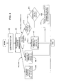
- FIG. 1 provides a block diagram of a system for implementing an exemplary embodiment of the present invention. It should be understood that the many of the elements described and illustrated throughout this specification are functional in nature and may be embodied in one or more physical entities or may take other forms beyond those described or depicted.
- the system shown in FIG. 1 includes a hands-free unit 102 , a telephone interface module (TIM) 104 and a wireless subscriber terminal 106 .
- the wireless subscriber terminal 106 (which may be a cellular telephone, a personal digital assistant, or any other type of wireless communication device for instance) is shown coupled to a wireless communications network 108 (such as a cellular radio-frequency network for instance), which includes or is coupled with (directly or through one or more other networks or communication paths) a VAD server 124 .
- a wireless communications network 108 such as a cellular radio-frequency network for instance
- An exemplary hands-free unit 102 may include a microphone 112 , a single actuator (or, equivalently, “control”) 114 , and a switch 116 .
- the TIM 104 may in turn include an audio processing module 120 , a debounce module 118 , and a controller 122 .
- the actuator may be coupled with the switch.
- the microphone 112 may be coupled to the audio processing module 120
- the switch 116 may be coupled to the debounce module 118 .
- the debounce module 118 may in turn be coupled with the controller 122 .
- both the audio processing module 120 and the controller 122 may be coupled with the wireless subscriber terminal 106 .
- the interfaces linking together the various components of the hands-free unit 102 , the TIM 104 and the terminal 106 may be wired or wireless.
- one or more of the interfaces may use shielded twisted pair wire (for audio connections) and a stranded copper wire (for all other connections).
- one or more of the interfaces may be wireless interfaces facilitating communication between entities according to the well known Bluetooth recommendation for short-range wireless communications.
- the hands-free unit 102 , TIM 104 , and terminal 106 are all situated in a vehicle (such as, for instance, a car, truck, plane or ship), although the arrangement could just as well be in any other location such as an office, home, or on a person's body (e.g., as a portable hands-free unit).
- the hands-free unit (or one or more of its constituent parts) is preferably situated in close proximity to a user (such as a driver for instance), so that the user's voice can be readily picked up by the microphone and so that the user can readily engage the actuator.
- the actuator can be mounted onto the vehicle dashboard, or the actuator id may be provided as a foot pedal. Other examples are possible as well.
- a typical vehicle will include a speaker 10 , to which the audio processing module 120 of the TIM may be coupled, so as to facilitate emitting audio signals for the user to hear.
- the speaker could just as well be a headphone or earphone or other device that functions to emit audio signals for a user to hear.
- the speaker could be coupled to the TIM or to another entity via a wired or wireless interface.
- the microphone 112 of hands-free unit 102 may be any type of microphone that functions to capture human speech or other audio signals.
- the microphone 112 preferably functions to capture the human speech, to convert the speech into an analog electrical signal, and to send the analog electrical signal to the audio processing module 120 of TIM 104 .
- the signal from the microphone may be provided to the audio processing module 120 via a wired or wireless transmission or by any other means.
- the actuator 114 can take any of a variety of forms as well. Preferably, however, the actuator should be easy for a user to operate, without unduly distracting the user.
- some examples of types of actuators include (i) a pushbutton switch or pedal, (ii) a heat-activated switch, (iii) a touch-sensitive pad, and (iv) a rotary dial.
- the actuator may have a number of preset positions or states (recognizing that an actuator without moving parts may not have “positions” but may have only “states” in relation to an underlying state machine or controller), such as “in” (e.g., on) and “out” (e.g., off) for instance. Other examples are possible as well.
- the control takes the form of a spring-loaded pushbutton device that works in combination with switch 116 to open or close a electrical circuit.
- a user may causes the switch 116 to be closed, which may consequently cause an electrical signal to be sent (via a wired or wireless connection) from a signal source to the controller 122 of the TIM 104 or may otherwise cause the controller 122 to detect that the actuator was engaged.
- the electrical signal may effectively indicate a characteristic of the actuation. For instance, if the electrical signal lasts for a particular duration, the signal may indicate that the user engaged the actuator for that duration.
- the audio processing module 120 of the TIM 104 may function to convert an analog electrical signal provided from the microphone 112 into a digital electrical signal, which the TIM 104 may then provide to the wireless subscriber terminal 106 for transmission into network 108 .
- the audio processing module 120 may function to convert a digital signal provided from the wireless subscriber terminal 106 into an analog electrical signal, which the audio processing unit may then provide to speaker 110 to be emitted for a user to hear.
- the debounce module 118 may function to clean the electrical signal provided from switch 116 .
- the resulting electrical signal may contain spikes or other undesirable characteristics.
- the debounce module 118 may function by means well known to those skilled in the art to remove the spikes and other undesirable characteristics, so as to present a substantially “clean” electrical signal to the controller 122 .
- the controller 122 may also take any of a variety of forms.
- the controller may comprise a microprocessor, a memory and various sets of machine language instructions (defining “routines”, “programs” or “program logic”) stored in the memory and executable by the microprocessor to carry out various functions described herein.
- the memory which may comprise volatile memory (e.g., RAM) and/or non-volatile memory (Flash), may serve to store data, such as indications of the state of subscriber terminal 106 (such as whether the terminal is on or off, whether the terminal is engaged in a call, and, if so, with whom the terminal is currently connected), indications of numbers or other digits or characters to have the terminal dial in particular instances, and a message set defining signals that can be sent to the wireless subscriber terminal so as to cause the subscriber terminal to carry out various functions.
- the application program interface (API) or other data maintained by controller in memory can be modified or updated through a download from a server on wireless network 108 via terminal 106 .
- API application program interface
- the controller 122 may thus receive an actuation signal from the debounce module 118 .
- the controller may interpret the actuation signal as simply an indication that the actuator has been engaged.
- the controller may analyze the actuation signal and thereby determine that the signal lasted for at least a predefined duration, such as 1.5 seconds, for instance, which may cause the controller to conclude that the actuator has been engaged for at least that predefined duration.
- the actuation signal may carry other possibly more specific information, which the controller 122 may be programmed to recognize.
- the controller 122 is preferably arranged to determine or to know the status of the wireless subscriber terminal at any given moment.
- the coupling between terminal 106 and controller 122 may carry signals indicating that the terminal is (i) powered on, (ii) currently engaged in a call, (iii) currently ringing—i.e., receiving an incoming call—, or any other particular state.
- the controller 122 may either have access to this status information via that coupling, and/or the controller 122 may store the status information in its memory for access when it needs it.
- Communications including status information, between the wireless subscriber terminal 106 and the controller 122 may utilize a data signaling and control (DTC) protocol.
- DTC data signaling and control
- an open DTC protocol such as the AT communications protocol may be used, and, in particular, the command set within that protocol.
- the protocol may be an open, non-proprietary protocol or a proprietary protocol.
- Other examples and types of protocols are possible.
- status information may be communicated between the wireless subscriber terminal 106 and the controller 122 using a packet of data that is, for example, one byte long. Other formats may be used to communicate status information, as well.
- the controller 122 may programmatically analyze the actuation signal and may note the status of the wireless subscriber terminal. In the exemplary embodiment, the controller may determine an action for the wireless subscriber terminal to take, based on a combination of (i) information derived from the actuation signals and (ii) the status of the subscriber terminal.
- the action to be taken may itself take a variety of forms. By way of example, the action may be: (i) simulate dialing of a specified sequence of digits and/or characters, (ii) simulate dialing of the “Talk” key, or (iii) simulate dialing of the “End” key.
- the controller 122 then preferably sends a signal to the wireless subscriber terminal providing an instruction for the wireless subscriber terminal to take the designated action.
- the instruction signal may take any form (such as a code or series of codes for instance), as long as the subscriber terminal understands the meaning of the code (as a directive indicative of the action to be taken) and can therefore act responsively.
- the code may, for example, be a one-byte-long packet. Other data structures and other lengths are possible.
- the wireless subscriber terminal receives the instruction, it then responsively carries out the action indicated. For example, if the instruction is to dial the “*” digit, then the wireless subscriber terminal preferably acts as if a user had manually dialed the “*” digit.
- the action to be taken by the wireless subscriber terminal may have various effects, depending on the state of the terminal, the state of an entity with which the terminal is currently communicating (if any), and the state of subscriber profiles in the network for instance. For example, if the terminal is currently engaged in a call with another entity, then (i) if the action is dialing the “End” button, then the call may be terminated just as if the user had manually pressed the “End” button, and (ii) if the action is dialing a sequence of digits, then the digits would be received by the other entity and the result of dialing the digits may therefore depend on the configuration or state of the other entity.
- the terminal may answer the call, just as if the user had manually pressed the “Talk” button, while (ii) if the action is pressing a sequence of digits followed by the “Talk” button, then the terminal may initiate a call based on the dialed digits, just as if the user had manually dialed the digits.
- Other examples are possible as well.
- the VAD server has access to an authorization database, indicating the identities of subscriber terminals that have subscribed to VAD service.
- the database may be keyed to mobile identification numbers (i.e., directory numbers) of subscriber terminals or any other information.
- the VAD server preferably includes a processor, a memory, and a set of machine language instructions and data stored in the memory and executable by the processor to carry out various functions described herein. For instance, aside from being able to recognize and act upon speech signals from a user, the VAD server may be programmed to recognize various tones (such as dual-tone-modulated-frequency (DTMF) tones) and to take predefined actions in response.
- DTMF dual-tone-modulated-frequency
- a “**” tone sequence i.e., the tones that would result if a user pressed the “*” key twice
- a “**” tone sequence may mean that the VAD server should disconnect a call that is currently in progress.
- a local serving system e.g., an MSC and/or visitor location register (VLR)
- a central controller e.g., a service control point (SCP) or home location register (HLR)
- VAD server which may be embodied in a service node (SN) or intelligent peripheral (IP) for instance
- the profile may indicate that, when the switch receives the sole dialed digit “*” from a subscriber terminal, the switch should connect the terminal to the VAD server.
- the switch may indicate that, when the switch receives the sole dialed digit “*” from a subscriber terminal, the switch should connect the terminal to the VAD server.
- Other examples are possible as well.
- Table 1 provides examples of actuation signals, states of the terminal, responsive actions taken by the wireless subscriber terminal at the controller's instruction, and possible results of those actions in accordance with an exemplary embodiment of the invention.
- the examples provided in this table are illustrative only, and other examples are possible as well.
- VAD server recognizes the “**” sequence as a request to disconnect the current call that the VAD server had connected for the terminal and to allow the user to speak another command. VAD server does so.
- Hands-free unit 214 includes a push button control 216 and a microphone 218 .
- the hands-free unit 214 may itself include the TIM.
- the hands-free unit may then be coupled to a wireless device 202 via a cable 210 and connector 208 .
- the connector 208 may have an end portion 206 that can be inserted into a corresponding receptacle 204 in the wireless device.
- the hands-free unit 214 may have a clip 220 .
- the clip 220 may be used to connect the hands-free unit 214 to a person's clothes or to another entity.
- FIG. 3 in turn shows another embodiment of an exemplary hands-free unit 318 .
- the hands-free unit 318 includes a rotary dial 324 and a microphone 320 .
- the hands-free unit may include the TIM and may be coupled to a wireless device (not shown) via a cable 326 and a connector (not shown).
- a flowchart depicting an exemplary operation of the system shown in FIG. 1 is provided.
- the steps illustrated and described are meant only to be examples of possible functions.
- a user may press a button or otherwise engage an actuator.
- the TIM then determines the state of the wireless device.
- the wireless device may be in one of the following three states: (i) powered on but idle, (ii) powered on, idle, and receiving an incoming call, or (iii) powered on and connected to a call. Other examples of states are possible, depending, for instance, on the type of wireless device at issue.
- the TIM sends a respective command sequence to the wireless device, causing the wireless device to dial the VAD server.
- the command sequence may, for instance, cause the wireless device to dial a feature code that the telecommunications network may convert into a directory number of a port at the VAD server, or it may cause the wireless device to dial a telephone number (such as a toll free number for instance) that will similarly amount to initiation of a call to the VAD server.
- the command “sequence” may be one or more digits and may take other forms and include other information as well.
- the TIM determines that the wireless device is on, idle and receiving an incoming call, then, at step 408 , the TIM issues a command to the wireless device to answer the call, and the wireless device would do so accordingly. Still alternatively, if the TIM determines that the wireless device is on and connected to a call, then, at step 410 the TIM determines whether the actuation signal indicates that the user engaged the actuator for at least some predefined duration. If so, then, at step 412 , the TIM issues a command to the wireless device to terminate the call (whether or not the call was placed through the VAD server), and the wireless device acts accordingly.
- the TIM determines whether the current call is connected via the VAD) server (by reference to state information stored in the TIM controller's memory). If so, then, at step 416 , the TIM issues a command to the wireless device to send a signal to the VAD server that will instruct the VAD server to terminate the current call but to stay connected with the wireless device so as to allow the user to initiate another VAD-based call.
- Communications, including status information, between the wireless subscriber terminal and the TIM may utilize a data signaling and control (DTC) protocol.
- DTC data signaling and control
- an open DTC protocol such as the AT communications protocol may be used, and, in particular, the command set within that protocol.
- the protocol may be an open, non-proprietary protocol or a proprietary protocol. Other examples and types of protocols are possible.
Abstract
Description
| TABLE 1 | |||
| Actuation | Terminal State | Terminal Action | Result |
| One press | On and idle | Dial “*” and then “Talk” | Telecom network connects the call to |
| (and in a given | (which the service | the VAD server or other such predefined | |
| service area) | area recognizes as a | entity. VAD server may then query the | |
| feature code) | terminal for an authorization code, | ||
| which the TIM controller may | |||
| responsively cause the terminal to dial | |||
| out. | |||
| One press | On an idle | Dial 1-800-xxx-xxxx | Telecom network connects the call to |
| (and out of the | and then “Talk” | the VAD server or other such predefined | |
| given service | entity. VAD server may then query the | ||
| area) | terminal for an authorization code, | ||
| which the TIM controller may | |||
| responsively cause the terminal to dial | |||
| out. | |||
| Press and hold | In call | Dial “End” | Terminal disconnects the call in |
| progress. | |||
| One press | Idle and ringing | Dial “Talk” | Terminal answers the incoming call. |
| One press | In VAD call | Dial “**” sequence | VAD server recognizes the “**” |
| sequence as a request to disconnect | |||
| the current call that the VAD server had | |||
| connected for the terminal and to allow | |||
| the user to speak another command. | |||
| VAD server does so. | |||
Claims (22)
Priority Applications (2)
| Application Number | Priority Date | Filing Date | Title |
|---|---|---|---|
| US09/724,004 US6865403B1 (en) | 2000-11-28 | 2000-11-28 | Method and system for simplified control of a subscriber terminal |
| US10/213,710 US7242966B1 (en) | 2000-11-28 | 2002-08-05 | Personal telematics device |
Applications Claiming Priority (1)
| Application Number | Priority Date | Filing Date | Title |
|---|---|---|---|
| US09/724,004 US6865403B1 (en) | 2000-11-28 | 2000-11-28 | Method and system for simplified control of a subscriber terminal |
Related Child Applications (1)
| Application Number | Title | Priority Date | Filing Date |
|---|---|---|---|
| US10/213,710 Continuation-In-Part US7242966B1 (en) | 2000-11-28 | 2002-08-05 | Personal telematics device |
Publications (1)
| Publication Number | Publication Date |
|---|---|
| US6865403B1 true US6865403B1 (en) | 2005-03-08 |
Family
ID=34218211
Family Applications (2)
| Application Number | Title | Priority Date | Filing Date |
|---|---|---|---|
| US09/724,004 Expired - Lifetime US6865403B1 (en) | 2000-11-28 | 2000-11-28 | Method and system for simplified control of a subscriber terminal |
| US10/213,710 Expired - Lifetime US7242966B1 (en) | 2000-11-28 | 2002-08-05 | Personal telematics device |
Family Applications After (1)
| Application Number | Title | Priority Date | Filing Date |
|---|---|---|---|
| US10/213,710 Expired - Lifetime US7242966B1 (en) | 2000-11-28 | 2002-08-05 | Personal telematics device |
Country Status (1)
| Country | Link |
|---|---|
| US (2) | US6865403B1 (en) |
Cited By (12)
| Publication number | Priority date | Publication date | Assignee | Title |
|---|---|---|---|---|
| EP0463951A2 (en) * | 1990-06-25 | 1992-01-02 | National Institute Of Genetics | Parallel information display system |
| US20030087675A1 (en) * | 1992-04-13 | 2003-05-08 | Koninklijke Philips Electronics N.V. | Speech recognition system for electronic switches in a non-wireline communications network |
| US20030190018A1 (en) * | 2002-04-03 | 2003-10-09 | Bleile Leonard George | Apparatus, method, media and signals for controlling a wireless communication appliance |
| US20040204072A1 (en) * | 2002-05-10 | 2004-10-14 | Wei Han | Apparatus and method for quick control of portable phone infrared transmission |
| US20050219062A1 (en) * | 2004-04-05 | 2005-10-06 | Van Bosch James A | Programmable foot switch useable in a communications user interface in a vehicle |
| US20060188117A1 (en) * | 2005-02-21 | 2006-08-24 | Kim Han-Il | Method of outputting audio signal for the hard-of-hearing and mobile communication terminal using the method |
| US20070072642A1 (en) * | 2005-09-27 | 2007-03-29 | Tita Kangas | Mobile communication terminal and method |
| US20080075065A1 (en) * | 2006-09-15 | 2008-03-27 | Plantronics, Inc. | Wireless VoIP headset with call origination capability |
| US20080232556A1 (en) * | 2007-03-20 | 2008-09-25 | Avaya Technology Llc | Keyword Alerting in Conference Calls |
| US7466800B1 (en) * | 2001-09-06 | 2008-12-16 | At&T Intellectual Property I, L.P. | Method and system of voice activated dialing using an intelligent peripheral in an advance intelligent network |
| US20110142221A1 (en) * | 2009-12-15 | 2011-06-16 | At&T Intellectual Property I, L.P. | System and method for automated group calling service based on key words |
| CN111866823A (en) * | 2019-04-26 | 2020-10-30 | 深圳市三诺声智联股份有限公司 | Wireless earphone charging equipment, interaction method and storage device |
Families Citing this family (25)
| Publication number | Priority date | Publication date | Assignee | Title |
|---|---|---|---|---|
| US20060217967A1 (en) * | 2003-03-20 | 2006-09-28 | Doug Goertzen | System and methods for storing and presenting personal information |
| JP4270031B2 (en) * | 2004-06-09 | 2009-05-27 | 株式会社デンソー | In-vehicle information registration / disclosure system, in-vehicle device and portable device |
| US7310521B2 (en) * | 2005-01-18 | 2007-12-18 | General Motors Corporation | Method to reduce modem call establishment time to a telematics unit |
| US20090191937A1 (en) * | 2007-06-04 | 2009-07-30 | Global Gaming Group, Inc. | Electronic gaming device and system with configurable multi-lingual audio and other player preference options |
| US20090215513A1 (en) * | 2008-02-25 | 2009-08-27 | Aruze Gaming America, Inc. | Gaming Machine. Gaming System with Interactive Feature and Control Method Thereof |
| US9412130B2 (en) | 2009-08-19 | 2016-08-09 | Allstate Insurance Company | Assistance on the go |
| US9659301B1 (en) | 2009-08-19 | 2017-05-23 | Allstate Insurance Company | Roadside assistance |
| US9384491B1 (en) | 2009-08-19 | 2016-07-05 | Allstate Insurance Company | Roadside assistance |
| US10453011B1 (en) | 2009-08-19 | 2019-10-22 | Allstate Insurance Company | Roadside assistance |
| US9070243B1 (en) | 2009-08-19 | 2015-06-30 | Allstate Insurance Company | Assistance on the go |
| US8787977B2 (en) | 2010-04-08 | 2014-07-22 | General Motors Llc | Method of controlling dialing modes in a vehicle |
| US8965696B2 (en) | 2012-06-05 | 2015-02-24 | Apple Inc. | Providing navigation instructions while operating navigation application in background |
| US9111380B2 (en) | 2012-06-05 | 2015-08-18 | Apple Inc. | Rendering maps |
| US10176633B2 (en) | 2012-06-05 | 2019-01-08 | Apple Inc. | Integrated mapping and navigation application |
| US10156455B2 (en) | 2012-06-05 | 2018-12-18 | Apple Inc. | Context-aware voice guidance |
| US9886794B2 (en) | 2012-06-05 | 2018-02-06 | Apple Inc. | Problem reporting in maps |
| US9418672B2 (en) | 2012-06-05 | 2016-08-16 | Apple Inc. | Navigation application with adaptive instruction text |
| US9997069B2 (en) | 2012-06-05 | 2018-06-12 | Apple Inc. | Context-aware voice guidance |
| US9482296B2 (en) | 2012-06-05 | 2016-11-01 | Apple Inc. | Rendering road signs during navigation |
| US20140179222A1 (en) * | 2012-12-21 | 2014-06-26 | Vishal Chaudhary | Method and system for effective and efficient service support |
| USD833896S1 (en) * | 2017-02-14 | 2018-11-20 | Tomtom Telematics B.V. | Telematics device |
| US10154145B1 (en) * | 2017-11-03 | 2018-12-11 | Republic Wireless, Inc. | Virtual telephony assistant |
| US11348170B2 (en) | 2018-03-27 | 2022-05-31 | Allstate Insurance Company | Systems and methods for identifying and transferring digital assets |
| US11748817B2 (en) | 2018-03-27 | 2023-09-05 | Allstate Insurance Company | Systems and methods for generating an assessment of safety parameters using sensors and sensor data |
| US10638309B1 (en) * | 2019-08-05 | 2020-04-28 | General Motors Llc | System and method to alter a telematics unit phone number |
Citations (12)
| Publication number | Priority date | Publication date | Assignee | Title |
|---|---|---|---|---|
| US5584052A (en) * | 1992-11-16 | 1996-12-10 | Ford Motor Company | Integrated microphone/pushbutton housing for voice activated cellular phone |
| US5794163A (en) * | 1993-07-27 | 1998-08-11 | Spectralink Corporation | Headset for hands-free wireless telephone |
| US5915228A (en) * | 1995-07-21 | 1999-06-22 | Sony Corporation | Terminal apparatus, radio communication terminal, and information input method |
| US6035217A (en) * | 1997-10-29 | 2000-03-07 | Sony Corporation Of Japan | One button cellular phone, system, and method for use |
| US6128514A (en) * | 1997-01-31 | 2000-10-03 | Bellsouth Corporation | Portable radiotelephone for automatically dialing a central voice-activated dialing system |
| US6240303B1 (en) * | 1998-04-23 | 2001-05-29 | Motorola Inc. | Voice recognition button for mobile telephones |
| US6377825B1 (en) * | 2000-02-18 | 2002-04-23 | Cellport Systems, Inc. | Hands-free wireless communication in a vehicle |
| US6449497B1 (en) * | 1998-03-10 | 2002-09-10 | Qualcomm Incorporated | System and method for use of feature codes in a wireless communication device |
| US6453169B1 (en) * | 1997-02-28 | 2002-09-17 | Qualcomm Incorporated | Portable radiotelephone with multiple function power key |
| US6459911B1 (en) * | 1998-09-30 | 2002-10-01 | Nec Corporation | Portable telephone equipment and control method therefor |
| US6519463B2 (en) * | 1996-02-28 | 2003-02-11 | Tendler Cellular, Inc. | Location based service request system |
| US6549790B1 (en) * | 1999-01-27 | 2003-04-15 | Telefonaktiebolaget Lm Ericsson (Publ) | Portable telecommunication apparatus for multiple audio accessories |
Family Cites Families (2)
| Publication number | Priority date | Publication date | Assignee | Title |
|---|---|---|---|---|
| US5912949A (en) * | 1996-11-05 | 1999-06-15 | Northern Telecom Limited | Voice-dialing system using both spoken names and initials in recognition |
| US6144723A (en) * | 1998-03-24 | 2000-11-07 | Nortel Networks Corporation | Method and apparatus for providing voice assisted call management in a telecommunications network |
-
2000
- 2000-11-28 US US09/724,004 patent/US6865403B1/en not_active Expired - Lifetime
-
2002
- 2002-08-05 US US10/213,710 patent/US7242966B1/en not_active Expired - Lifetime
Patent Citations (12)
| Publication number | Priority date | Publication date | Assignee | Title |
|---|---|---|---|---|
| US5584052A (en) * | 1992-11-16 | 1996-12-10 | Ford Motor Company | Integrated microphone/pushbutton housing for voice activated cellular phone |
| US5794163A (en) * | 1993-07-27 | 1998-08-11 | Spectralink Corporation | Headset for hands-free wireless telephone |
| US5915228A (en) * | 1995-07-21 | 1999-06-22 | Sony Corporation | Terminal apparatus, radio communication terminal, and information input method |
| US6519463B2 (en) * | 1996-02-28 | 2003-02-11 | Tendler Cellular, Inc. | Location based service request system |
| US6128514A (en) * | 1997-01-31 | 2000-10-03 | Bellsouth Corporation | Portable radiotelephone for automatically dialing a central voice-activated dialing system |
| US6453169B1 (en) * | 1997-02-28 | 2002-09-17 | Qualcomm Incorporated | Portable radiotelephone with multiple function power key |
| US6035217A (en) * | 1997-10-29 | 2000-03-07 | Sony Corporation Of Japan | One button cellular phone, system, and method for use |
| US6449497B1 (en) * | 1998-03-10 | 2002-09-10 | Qualcomm Incorporated | System and method for use of feature codes in a wireless communication device |
| US6240303B1 (en) * | 1998-04-23 | 2001-05-29 | Motorola Inc. | Voice recognition button for mobile telephones |
| US6459911B1 (en) * | 1998-09-30 | 2002-10-01 | Nec Corporation | Portable telephone equipment and control method therefor |
| US6549790B1 (en) * | 1999-01-27 | 2003-04-15 | Telefonaktiebolaget Lm Ericsson (Publ) | Portable telecommunication apparatus for multiple audio accessories |
| US6377825B1 (en) * | 2000-02-18 | 2002-04-23 | Cellport Systems, Inc. | Hands-free wireless communication in a vehicle |
Cited By (25)
| Publication number | Priority date | Publication date | Assignee | Title |
|---|---|---|---|---|
| EP0463951A2 (en) * | 1990-06-25 | 1992-01-02 | National Institute Of Genetics | Parallel information display system |
| EP0463951A3 (en) * | 1990-06-25 | 1993-08-04 | Fujitsu Limited | Parallel information display system |
| US20030087675A1 (en) * | 1992-04-13 | 2003-05-08 | Koninklijke Philips Electronics N.V. | Speech recognition system for electronic switches in a non-wireline communications network |
| US7551944B2 (en) * | 1992-04-13 | 2009-06-23 | Nuance Communications, Inc. | Speech recognition system for electronic switches in a non-wireline communications network |
| US7466800B1 (en) * | 2001-09-06 | 2008-12-16 | At&T Intellectual Property I, L.P. | Method and system of voice activated dialing using an intelligent peripheral in an advance intelligent network |
| US7162228B2 (en) * | 2002-04-03 | 2007-01-09 | Embedded Systems Products Inc. | Apparatus, method, media and signals for controlling a wireless communication appliance |
| US20030190018A1 (en) * | 2002-04-03 | 2003-10-09 | Bleile Leonard George | Apparatus, method, media and signals for controlling a wireless communication appliance |
| US20040204072A1 (en) * | 2002-05-10 | 2004-10-14 | Wei Han | Apparatus and method for quick control of portable phone infrared transmission |
| WO2005101866A1 (en) * | 2004-04-05 | 2005-10-27 | Motorola, Inc. | Programmable foot switch useable in a communications user interface in a vehicle |
| US7245898B2 (en) | 2004-04-05 | 2007-07-17 | Motorola, Inc. | Programmable foot switch useable in a communications user interface in a vehicle |
| US20050219062A1 (en) * | 2004-04-05 | 2005-10-06 | Van Bosch James A | Programmable foot switch useable in a communications user interface in a vehicle |
| US20060188117A1 (en) * | 2005-02-21 | 2006-08-24 | Kim Han-Il | Method of outputting audio signal for the hard-of-hearing and mobile communication terminal using the method |
| US8284975B2 (en) | 2005-02-21 | 2012-10-09 | Pantech Co., Ltd. | Method of outputting audio signal and mobile communication terminal using the method |
| US7738669B2 (en) * | 2005-02-21 | 2010-06-15 | Pantech&Curitel Communications, Inc. | Method of outputting audio signal for the hard-of-hearing and mobile communication terminal using the method |
| US20100208923A1 (en) * | 2005-02-21 | 2010-08-19 | Pantech Co. Ltd. | Method of outputting audio signal and mobile communication terminal using the method |
| US20070072642A1 (en) * | 2005-09-27 | 2007-03-29 | Tita Kangas | Mobile communication terminal and method |
| US7555311B2 (en) * | 2005-09-27 | 2009-06-30 | Nokia Corporation | Mobile communication terminal and method |
| US20080075065A1 (en) * | 2006-09-15 | 2008-03-27 | Plantronics, Inc. | Wireless VoIP headset with call origination capability |
| US20080232556A1 (en) * | 2007-03-20 | 2008-09-25 | Avaya Technology Llc | Keyword Alerting in Conference Calls |
| US8059807B2 (en) * | 2007-03-20 | 2011-11-15 | Avaya, Inc. | Keyword alerting in conference calls |
| US9112979B2 (en) | 2007-03-20 | 2015-08-18 | Avaya Inc. | Keyword alerting in conference calls |
| US9112978B2 (en) | 2007-03-20 | 2015-08-18 | Avaya Inc. | Keyword alerting in conference calls |
| US20110142221A1 (en) * | 2009-12-15 | 2011-06-16 | At&T Intellectual Property I, L.P. | System and method for automated group calling service based on key words |
| CN111866823A (en) * | 2019-04-26 | 2020-10-30 | 深圳市三诺声智联股份有限公司 | Wireless earphone charging equipment, interaction method and storage device |
| CN111866823B (en) * | 2019-04-26 | 2023-10-13 | 深圳市三诺声智联股份有限公司 | Wireless earphone charging equipment, interaction method and storage medium |
Also Published As
| Publication number | Publication date |
|---|---|
| US7242966B1 (en) | 2007-07-10 |
Similar Documents
| Publication | Publication Date | Title |
|---|---|---|
| US6865403B1 (en) | Method and system for simplified control of a subscriber terminal | |
| EP0554625B1 (en) | Cordless telephone arrangement | |
| US5864763A (en) | Digital wireless telephone system interface for analog telecommunications equipment | |
| JPH08500952A (en) | Memory dialing method for cellular phones | |
| WO1999038307A9 (en) | Voice enhanced phone card | |
| US6256611B1 (en) | Controlling a telecommunication service and a terminal | |
| EP1414224A3 (en) | Mobile communication terminal provided with handsfree function and controlling method thereof | |
| JPH098953A (en) | Telephone system and communication equipment | |
| KR950007091B1 (en) | The voice dialing method of cellular phone | |
| KR100606154B1 (en) | System and method for fixing subscriber based ring-back-tone sound source | |
| US20030181223A1 (en) | System and method for voice activated dialing | |
| KR100539887B1 (en) | option handling method of ring back tone signal service | |
| WO2004075521A1 (en) | Method and system for shortend dialing service based on telecommunication network | |
| KR20030003841A (en) | Operation control method in remote mobile phone | |
| KR100648351B1 (en) | Method for automatic dialing an extention telephone number in a mobile communication system | |
| KR200249938Y1 (en) | A voice-cognizable hands-free apparatus with an interrupt-generator by setting of a portable telephone | |
| KR200323834Y1 (en) | ACR(Auto Call Router) for Mobile Phone | |
| KR100241729B1 (en) | Method of answer for call | |
| KR100798372B1 (en) | Apparatus and method for remote phone call | |
| KR100504456B1 (en) | Method for automatically acknowledging/sending area number of handset | |
| KR100228019B1 (en) | Voice paging service method using voice activated dialing service | |
| JPH06217366A (en) | Message transmission system to busy subscriber in cellular telephone system | |
| JP2000324250A (en) | Method and circuit device for connecting mobile radio telephone to communication network for fixed network telephone | |
| JPH11252237A (en) | Device and method for remotely responding to individually stored telephone number | |
| EP1090517A1 (en) | Method and system for call redirection |
Legal Events
| Date | Code | Title | Description |
|---|---|---|---|
| AS | Assignment |
Owner name: SPRINT CORPORATION, MISSOURI Free format text: ASSIGNMENT OF ASSIGNORS INTEREST;ASSIGNOR:AVERKAMP, JOSEPH;REEL/FRAME:011304/0635 Effective date: 20001128 |
|
| AS | Assignment |
Owner name: SPRINT SPECTRUM L.P., MISSOURI Free format text: REQUEST FOR CORRECTED RECORDATION TO CHANGE THE COMPANY NAME FROM SPRINT CORPORATION TO "SPRINT SPECTRUM L.P." PREVIOUSLY RECORDED ON 11/28/00, REEL/FRAME 011304/0635.;ASSIGNOR:AVERKAMP, JOSEPH;REEL/FRAME:011744/0438 Effective date: 20001128 |
|
| STCF | Information on status: patent grant |
Free format text: PATENTED CASE |
|
| FPAY | Fee payment |
Year of fee payment: 4 |
|
| FPAY | Fee payment |
Year of fee payment: 8 |
|
| FPAY | Fee payment |
Year of fee payment: 12 |
|
| AS | Assignment |
Owner name: DEUTSCHE BANK TRUST COMPANY AMERICAS, NEW YORK Free format text: GRANT OF FIRST PRIORITY AND JUNIOR PRIORITY SECURITY INTEREST IN PATENT RIGHTS;ASSIGNOR:SPRINT SPECTRUM L.P.;REEL/FRAME:041937/0632 Effective date: 20170203 |
|
| AS | Assignment |
Owner name: DEUTSCHE BANK TRUST COMPANY AMERICAS, NEW YORK Free format text: SECURITY AGREEMENT;ASSIGNORS:T-MOBILE USA, INC.;ISBV LLC;T-MOBILE CENTRAL LLC;AND OTHERS;REEL/FRAME:053182/0001 Effective date: 20200401 |
|
| AS | Assignment |
Owner name: SPRINT SPECTRUM L.P., KANSAS Free format text: TERMINATION AND RELEASE OF FIRST PRIORITY AND JUNIOR PRIORITY SECURITY INTEREST IN PATENT RIGHTS;ASSIGNOR:DEUTSCHE BANK TRUST COMPANY AMERICAS;REEL/FRAME:052313/0299 Effective date: 20200401 |
|
| AS | Assignment |
Owner name: SPRINT SPECTRUM LLC, WASHINGTON Free format text: CHANGE OF NAME;ASSIGNOR:SPRINT SPECTRUM L.P.;REEL/FRAME:059044/0022 Effective date: 20210325 |
|
| AS | Assignment |
Owner name: SPRINT SPECTRUM LLC, KANSAS Free format text: RELEASE BY SECURED PARTY;ASSIGNOR:DEUTSCHE BANK TRUST COMPANY AMERICAS;REEL/FRAME:062595/0001 Effective date: 20220822 Owner name: SPRINT INTERNATIONAL INCORPORATED, KANSAS Free format text: RELEASE BY SECURED PARTY;ASSIGNOR:DEUTSCHE BANK TRUST COMPANY AMERICAS;REEL/FRAME:062595/0001 Effective date: 20220822 Owner name: SPRINT COMMUNICATIONS COMPANY L.P., KANSAS Free format text: RELEASE BY SECURED PARTY;ASSIGNOR:DEUTSCHE BANK TRUST COMPANY AMERICAS;REEL/FRAME:062595/0001 Effective date: 20220822 Owner name: SPRINTCOM LLC, KANSAS Free format text: RELEASE BY SECURED PARTY;ASSIGNOR:DEUTSCHE BANK TRUST COMPANY AMERICAS;REEL/FRAME:062595/0001 Effective date: 20220822 Owner name: CLEARWIRE IP HOLDINGS LLC, KANSAS Free format text: RELEASE BY SECURED PARTY;ASSIGNOR:DEUTSCHE BANK TRUST COMPANY AMERICAS;REEL/FRAME:062595/0001 Effective date: 20220822 Owner name: CLEARWIRE COMMUNICATIONS LLC, KANSAS Free format text: RELEASE BY SECURED PARTY;ASSIGNOR:DEUTSCHE BANK TRUST COMPANY AMERICAS;REEL/FRAME:062595/0001 Effective date: 20220822 Owner name: BOOST WORLDWIDE, LLC, KANSAS Free format text: RELEASE BY SECURED PARTY;ASSIGNOR:DEUTSCHE BANK TRUST COMPANY AMERICAS;REEL/FRAME:062595/0001 Effective date: 20220822 Owner name: ASSURANCE WIRELESS USA, L.P., KANSAS Free format text: RELEASE BY SECURED PARTY;ASSIGNOR:DEUTSCHE BANK TRUST COMPANY AMERICAS;REEL/FRAME:062595/0001 Effective date: 20220822 Owner name: T-MOBILE USA, INC., WASHINGTON Free format text: RELEASE BY SECURED PARTY;ASSIGNOR:DEUTSCHE BANK TRUST COMPANY AMERICAS;REEL/FRAME:062595/0001 Effective date: 20220822 Owner name: T-MOBILE CENTRAL LLC, WASHINGTON Free format text: RELEASE BY SECURED PARTY;ASSIGNOR:DEUTSCHE BANK TRUST COMPANY AMERICAS;REEL/FRAME:062595/0001 Effective date: 20220822 Owner name: PUSHSPRING, LLC, WASHINGTON Free format text: RELEASE BY SECURED PARTY;ASSIGNOR:DEUTSCHE BANK TRUST COMPANY AMERICAS;REEL/FRAME:062595/0001 Effective date: 20220822 Owner name: LAYER3 TV, LLC, WASHINGTON Free format text: RELEASE BY SECURED PARTY;ASSIGNOR:DEUTSCHE BANK TRUST COMPANY AMERICAS;REEL/FRAME:062595/0001 Effective date: 20220822 Owner name: IBSV LLC, WASHINGTON Free format text: RELEASE BY SECURED PARTY;ASSIGNOR:DEUTSCHE BANK TRUST COMPANY AMERICAS;REEL/FRAME:062595/0001 Effective date: 20220822 |