US6880545B2 - Dual conveyor jet impingement oven - Google Patents
Dual conveyor jet impingement oven Download PDFInfo
- Publication number
- US6880545B2 US6880545B2 US10/650,422 US65042203A US6880545B2 US 6880545 B2 US6880545 B2 US 6880545B2 US 65042203 A US65042203 A US 65042203A US 6880545 B2 US6880545 B2 US 6880545B2
- Authority
- US
- United States
- Prior art keywords
- heated air
- accordance
- air distribution
- heating apparatus
- disposed
- Prior art date
- Legal status (The legal status is an assumption and is not a legal conclusion. Google has not performed a legal analysis and makes no representation as to the accuracy of the status listed.)
- Expired - Lifetime
Links
- 230000009977 dual effect Effects 0.000 title abstract description 12
- 238000010438 heat treatment Methods 0.000 claims abstract description 96
- 239000012530 fluid Substances 0.000 claims abstract description 23
- 230000007704 transition Effects 0.000 claims description 15
- 235000013305 food Nutrition 0.000 description 18
- 238000010411 cooking Methods 0.000 description 4
- 238000009792 diffusion process Methods 0.000 description 4
- 238000010586 diagram Methods 0.000 description 2
- 230000000694 effects Effects 0.000 description 2
- 235000013410 fast food Nutrition 0.000 description 2
- 239000000463 material Substances 0.000 description 2
- VNWKTOKETHGBQD-UHFFFAOYSA-N methane Chemical compound C VNWKTOKETHGBQD-UHFFFAOYSA-N 0.000 description 2
- 235000013550 pizza Nutrition 0.000 description 2
- 235000014510 cooky Nutrition 0.000 description 1
- 238000001816 cooling Methods 0.000 description 1
- 238000001125 extrusion Methods 0.000 description 1
- 239000000446 fuel Substances 0.000 description 1
- 238000009434 installation Methods 0.000 description 1
- 239000011810 insulating material Substances 0.000 description 1
- 235000012054 meals Nutrition 0.000 description 1
- 238000012986 modification Methods 0.000 description 1
- 230000004048 modification Effects 0.000 description 1
- 239000003345 natural gas Substances 0.000 description 1
- 230000009467 reduction Effects 0.000 description 1
- 238000000926 separation method Methods 0.000 description 1
- 230000003068 static effect Effects 0.000 description 1
Images


Classifications
-
- A—HUMAN NECESSITIES
- A21—BAKING; EDIBLE DOUGHS
- A21B—BAKERS' OVENS; MACHINES OR EQUIPMENT FOR BAKING
- A21B1/00—Bakers' ovens
- A21B1/02—Bakers' ovens characterised by the heating arrangements
- A21B1/24—Ovens heated by media flowing therethrough
- A21B1/245—Ovens heated by media flowing therethrough with a plurality of air nozzles to obtain an impingement effect on the food
Definitions
- This invention relates to ovens for cooking foods, in particular commercial conveyor ovens typically employed in baking foods, such as pizzas and the like. It will, however, be apparent to those skilled in the art that such conveyor ovens are suitable for use in a variety of non-food related applications, and commercial conveyor ovens for non-food related applications are deemed to be within the scope of this invention.
- Impingement ovens are primarily employed in fast food restaurants for rapid cooking of foods such as pizzas, pre-cooked meals, cookies and the like. Such ovens employ heated air streams which impinge directly upon the surface of the food being cooked. Such ovens typically employ an air handling system, which is responsible for the supply and distribution of heated air to the food and a heating chamber or space in which the food is actually cooked. The food is typically transported into and through the heating space by one or more conveyors. To provide for rapid heating, heated air streams are provided to the heating chamber in such a manner whereby the air streams impinge directly on both the top and bottom of the device carrying the food, typically by heated air plenums, disposed above and below the conveyor, having perforated heated air distribution plates through which the heated air is directed onto the food surfaces.
- a major problem associated with conveyor ovens is the exchange of internal hot air with room air due to losses from the conveyor tunnel/heating space.
- a further problem is the low speed of baking certain foods due to low heat transfer.
- Yet a further problem is the limited kitchen space available in fast food restaurants for conveyor ovens capable of meeting the peak demands of their customers.
- a heating apparatus comprising at least one wall enclosing a blower box and forming at least one air inlet opening and at least two air outlet openings and at least one heating section wall defining a heating space adjacent to and in fluid communication with the blower box.
- Two spaced apart pairs of spaced apart heated air distribution plenums are disposed within the heating space and form a return air conduit therebetween, which return air conduit has a return outlet end in fluid communication with the at least one air inlet opening of the blower box.
- Each of the spaced apart heated air distribution plenums includes a heated air inlet opening in fluid communication with the at least two air outlet openings.
- a horizontal heating surface is disposed between each pair of spaced apart heated air distribution plenums and each of the heated air distribution plenums comprises a substantially horizontally disposed, perforated heated air distribution plate facing the horizontal heating surface.
- the horizontal heating surface is typically a porous conveyor for conveying items to be heated, such as food, whereby the heated air streams ejected from the lower of the spaced apart heated air distribution plenums directly impinge onto the bottom surface thereof.
- Incorporated into the heated air distribution plates is a novel jet nozzle design whereby the air streams ejected from the heated air distribution plenums vertically impinge upon the food surface and porous conveyor, which design reduces the exchange of internal heated air with room air, thereby increasing oven uniformity and efficiency.
- FIG. 1 is a schematic diagram showing a simplified plan view of a dual conveyor oven in accordance with one embodiment of this invention
- FIG. 2 is a schematic lateral view of a dual conveyor oven in accordance with one embodiment of this invention.
- FIG. 3 is a perspective view the heating space of a dual conveyor oven in accordance with one embodiment of this invention.
- FIG. 4 is a view of the dual conveyor oven shown in FIG. 2 taken along the line IV—IV;
- FIG. 5 is a view of the dual conveyor oven shown in FIG. 2 taken along the line V—V;
- FIG. 6 is a diagram showing turning vanes for directing air flow from an air supply blower output into a dual conveyor oven in accordance with one embodiment of this invention
- FIG. 7 is a partial perspective view of a heated air distribution plate in a dual conveyor oven in accordance with one embodiment of this invention.
- FIG. 8 is a view of a portion of a heated air distribution plate looking in the direction of flow of heated air within the heated air distribution plenum of a dual conveyor oven in accordance with one embodiment of this invention.
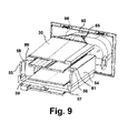
- FIG. 9 is a perspective view of a portion of the interior of a dual conveyor oven in accordance with one embodiment of this invention.
- dual conveyor oven 10 comprises a blower box 47 defined by a blower box back wall 15 , blower box sidewalls 13 and blower box front wall 22 disposed opposite blower box back wall 15 .
- air plenum 14 Disposed within blower box 47 is air plenum 14 having plenum sidewalls 45 .
- insulating material 46 Disposed between plenum sidewalls 45 and blower box sidewalls 13 is an insulating material 46 .
- a heating space defined by front wall 11 , oppositely disposed back wall 12 and side walls 23 .
- back wall 12 of the heating space and blower box front wall 22 may be formed as a single wall, common to both the heating space and blower box 47 .
- blowers 18 and 19 Disposed within air plenum 14 are two blowers 18 and 19 , each of which comprises a motor, 17 and 16 , respectively, external to air plenum 14 .
- Each motor 16 , 17 comprises a drive shaft 27 , 28 which is oriented parallel to the direction of air flow from air plenum 14 into the heating space as indicated by arrow 29 .
- Each blower 18 , 19 has a blower outlet 21 in fluid communication with heated air distribution system 20 disposed within the heating space.
- blower diameter be as large as possible. This is achieved by the diagonal positioning of the blowers within air plenum 14 .
- one problem encountered with ovens of this design is the left to right (or right to left) variation in airflow caused by the left to right (or left to right) momentum created by the blowers. This causes left to right (or right to left) asymmetry of air velocities within the heating space. This problem is addressed in accordance with one embodiment of this invention by modification of the transitioning conduit between the blower outlets and the heated air distribution plenums as described herein below.
- 90° elbow transition section or conduit 60 Connected to blower outlet 21 of each of blowers 18 , 19 is a 90° elbow transition section or conduit 60 , only one of which is shown in FIG. 1 for the sake of clarity, which 90° elbow transition section provides a conduit for fluid communication between blower outlets 21 and heated air distribution system 20 .
- Disposed within 90° elbow transition section 60 in accordance with one preferred embodiment of this invention is at least one turning vane 61 , 62 shown in FIG. 6 .
- the use of turning vanes 61 , 62 in the 90° elbow transition section results in improved aerodynamics, producing reduced airflow resistance and improved, more uniform air distribution within heated air distribution system 20 .
- FIG. 2 As suggested by FIG. 2 and as more clearly depicted in FIG.
- blower motors 16 , 17 and blowers 18 , 19 are positioned diagonally with respect to each other. Such relative positioning enables the use of larger size blowers for a given size air plenum 14 which, in turn, can produce higher amounts of heat transfer.
- burner tube 34 disposed within air plenum 14 is a burner tube 34 which extends along substantially the entire distance between blower box sidewalls 13 of blower box 47 and is the heat exchange means by which heat is transferred to the air flowing into blowers 18 , 19 by which it is transmitted into heated air distribution system 20 .
- burner tube 34 Disposed within burner tube 34 is a burner 26 , typically fueled by a gaseous fuel, preferably natural gas, which produces a flame within burner tube 34 , thereby providing the heat source for burner tube 34 .
- Heated air distribution system 20 in accordance with one embodiment of this invention as shown in FIG. 2 comprises two spaced apart pairs of spaced apart first and second heated air distribution plenums 30 , 31 and 32 , 33 . Between the spaced apart pairs of spaced apart heated air distribution plenums is formed a return air conduit 24 having a return air outlet 25 in fluid communication with air plenum 14 , which return air conduit 24 comprises sidewalls 54 , 55 extending between the two spaced apart pairs of spaced apart heated air distribution plenums 30 , 31 and 32 , 33 , as shown in FIGS. 3 and 9 .
- Each of the heated air distribution plenums 30 , 31 , 32 and 33 comprises a substantially horizontally oriented, heated air distribution plate 49 , 50 , 51 and 52 , each of which heated air distribution plates is disposed on the side of the heated air distribution plenum facing the opposed heated air distribution plenum of the corresponding pair of spaced apart heated air distribution plenums. That is, heated air distribution plate 49 of the top lower conveyor heated air distribution plenum 32 is oriented to face heated air distribution plate 50 of the bottom lower conveyor heated air distribution plenum 33 .
- Each heated air distribution plate 65 forms a plurality of heated air distribution openings 66 through which heated air, indicated by arrows 70 , as shown in FIG.
- heated air distribution plenums 30 , 31 , 32 and 33 introduced into heated air distribution plenums 30 , 31 , 32 and 33 through heated air distribution plenum inlet openings 35 , 36 , 37 and 38 , respectively, as shown in FIG. 4 , is distributed, as indicated by arrows 71 , onto a food product disposed on conveyors 53 disposed between the heated air distribution plenums of each pair of spaced apart heated air distribution plenums.
- a flow diverter 40 Disposed between the heated air distribution plenum inlet openings of each pair of openings 35 , 36 and 37 , 38 is a flow diverter 40 having an arcuate profile whereby heated air from blowers 18 , 19 is split between the heated air distribution plenums of each spaced apart pair of heated air distribution plenums 30 , 31 and 32 , 33 .
- each heated air distribution plenum, 30 , 31 , 32 and 33 is vertically tapered, with the widest portion oriented toward air plenum 14 .
- return air conduit 24 conveys air from the front wall 11 of the heating space at the corners of the return air conduit 24 into air plenum 14 such that the air is diffused horizontally to the full width of air plenum 14 and the full height of the vertical distance between the spaced apart pairs of spaced apart heated air distribution plenums 30 , 31 and 32 , 33 .
- the return air enters return air conduit 24 through return air inlet openings 56 , 57 , 58 and 59 disposed at the corners of return air conduit 24 proximate front wall 11 as shown in FIGS. 3 and 9 .
- the ends of sidewalls 54 , 55 disposed proximate front wall 11 are provided with inwardly oriented convex profiles 80 , 81 , as shown in FIG. 9 .
- Hot spots in the air plenum occur if parts of the burner tube 34 are not cooled due to a lack of air velocity over those parts of the burner tube. Such hot spots create cooking non-uniformities and non-uniform aerodynamics at the blower inlets, reducing blower efficiency.
- the return air conduit 24 with its sidewalls serving to diffuse air to the full width of the air plenum 14 , eliminates stagnant spots therein, thereby reducing poor inlet characteristics for the blowers.
- Disposed adjacent to the outer walls of the top upper heated air distribution plenum 30 and the bottom lower heated air distribution plenum 33 are secondary air return conduits 41 , 42 , 43 and 44 , as shown in FIG. 4 , having an opening 75 , as shown in FIG. 3 , through which a portion of the heated air from between each pair of heated air distribution plenums 30 , 31 and 32 , 33 is returned to air plenum 14 .
- Secondary return air from secondary air return conduits 41 , 42 , 43 and 44 forms air jets upon entering air plenum 14 , which impact against the blower box back wall 15 , creating rotary air patterns that are superimposed on the substantially horizontal flow of return air flowing into air plenum 14 from return air conduit 24 , causing the air to be blown back across burner tube 34 to be heated before entering the blower inlets.
- the blower inlets are disposed at approximately the same height as burner tube 34 so that undesirable inlet effects that can reduce airflow and efficiency are minimized.
- FIGS. 7 and 8 show portions of a heated air distribution plate 65 used for producing substantially vertical air jets in accordance with one embodiment of this invention. As shown, each of the openings 66 of heated air distribution plate 65 , which may be disposed on either face or side of the plate, that is, facing either the material to be heated or facing the interior of the heated air distribution plenum, is surrounded by a nozzle which is asymmetrical in terms of nozzle length.
- Each nozzle has a section 67 oriented towards the front of the heating space which is longer in length than a section 68 disposed opposite section 67 . It will be apparent to those skilled in the art that section 68 may have zero length and, as such, is deemed to be within the scope of this invention.
- each blower provides air to one of the pairs of spaced apart heated air distribution plenums 30 , 31 and 32 , 33 .
- a diffusion transition 85 disposed between the 90 degree elbow 60 and the heated air distribution plenums is a diffusion transition 85 to enable distribution of the heated air across the entire width of the heated air distribution plenums.
- the wide angle of diffusion causes separation at the ends of the diffusion transition, thereby causing lower air velocities at the rear corners of the heating space.
- These spots of low air velocity are substantially eliminated by the disposition of guide vanes 90 within the diffusion transition 85 , as shown in FIG. 9 .
- guide vanes 90 improve the left to right baking uniformity, improve aerodynamics, reduce pressur drop and increase airflow and heat transfer coeeficients.
Abstract
Description
Claims (32)
Priority Applications (1)
| Application Number | Priority Date | Filing Date | Title |
|---|---|---|---|
| US10/650,422 US6880545B2 (en) | 2003-08-28 | 2003-08-28 | Dual conveyor jet impingement oven |
Applications Claiming Priority (1)
| Application Number | Priority Date | Filing Date | Title |
|---|---|---|---|
| US10/650,422 US6880545B2 (en) | 2003-08-28 | 2003-08-28 | Dual conveyor jet impingement oven |
Publications (2)
| Publication Number | Publication Date |
|---|---|
| US20050045173A1 US20050045173A1 (en) | 2005-03-03 |
| US6880545B2 true US6880545B2 (en) | 2005-04-19 |
Family
ID=34217156
Family Applications (1)
| Application Number | Title | Priority Date | Filing Date |
|---|---|---|---|
| US10/650,422 Expired - Lifetime US6880545B2 (en) | 2003-08-28 | 2003-08-28 | Dual conveyor jet impingement oven |
Country Status (1)
| Country | Link |
|---|---|
| US (1) | US6880545B2 (en) |
Cited By (30)
| Publication number | Priority date | Publication date | Assignee | Title |
|---|---|---|---|---|
| US20080216812A1 (en) * | 2007-03-10 | 2008-09-11 | Dougherty Carl J | Compact conveyor oven |
| US20080264402A1 (en) * | 2007-04-30 | 2008-10-30 | Bramhall Marcus E | Ovens having a cold air return baffle and methods for circulating air in an oven |
| US20090001068A1 (en) * | 2007-06-28 | 2009-01-01 | Bramhall Marcus E | Apparatus and methods for cooling an oven conveyor motor |
| US20090045191A1 (en) * | 2006-02-21 | 2009-02-19 | Rf Dynamics Ltd. | Electromagnetic heating |
| US20090236334A1 (en) * | 2006-07-10 | 2009-09-24 | Rf Dynamics Ltd | Food preparation |
| US20090236335A1 (en) * | 2006-02-21 | 2009-09-24 | Rf Dynamics Ltd. | Food preparation |
| US20100115785A1 (en) * | 2006-02-21 | 2010-05-13 | Bora Appliances Limited | Drying apparatus and methods and accessories for use therewith |
| WO2010135693A1 (en) * | 2009-05-22 | 2010-11-25 | Merrychef Limited | Radial jet air impingement nozzle, oven and method |
| US7994962B1 (en) | 2007-07-17 | 2011-08-09 | Drosera Ltd. | Apparatus and method for concentrating electromagnetic energy on a remotely-located object |
| US20110198343A1 (en) * | 2008-11-10 | 2011-08-18 | Rf Dynamics Ltd. | Device and method for heating using rf energy |
| US8389916B2 (en) | 2007-05-21 | 2013-03-05 | Goji Limited | Electromagnetic heating |
| US8733236B2 (en) | 2011-09-20 | 2014-05-27 | Ovention, Inc. | Matchbox oven |
| US20140199446A1 (en) * | 2013-01-11 | 2014-07-17 | Star Manufacturing International, Inc. | Split-Belt Conveyor Toaster |
| US20150150269A1 (en) * | 2012-08-01 | 2015-06-04 | Frito-Lay North America, Inc. | Continuous process and apparatus for making a pita chip |
| US9131543B2 (en) | 2007-08-30 | 2015-09-08 | Goji Limited | Dynamic impedance matching in RF resonator cavity |
| US9215756B2 (en) | 2009-11-10 | 2015-12-15 | Goji Limited | Device and method for controlling energy |
| US9288997B2 (en) | 2011-03-31 | 2016-03-22 | Ovention, Inc. | Matchbox oven |
| US9326639B2 (en) | 2011-03-31 | 2016-05-03 | Ovention, Inc. | Oven having a rotating door |
| US9372006B2 (en) | 2013-05-06 | 2016-06-21 | Ovention, Inc. | Compact oven |
| WO2016126843A1 (en) * | 2015-02-05 | 2016-08-11 | Frito-Lay North America, Inc. | An improved continuous process and apparatus for making a pita chip |
| US9480364B2 (en) | 2011-03-31 | 2016-11-01 | Ovention, Inc. | Oven having an H-shaped rotating door |
| US9677774B2 (en) | 2015-06-08 | 2017-06-13 | Alto-Shaam, Inc. | Multi-zone oven with variable cavity sizes |
| US9879865B2 (en) | 2015-06-08 | 2018-01-30 | Alto-Shaam, Inc. | Cooking oven |
| US10088172B2 (en) | 2016-07-29 | 2018-10-02 | Alto-Shaam, Inc. | Oven using structured air |
| US10337745B2 (en) | 2015-06-08 | 2019-07-02 | Alto-Shaam, Inc. | Convection oven |
| US10674570B2 (en) | 2006-02-21 | 2020-06-02 | Goji Limited | System and method for applying electromagnetic energy |
| US10890336B2 (en) | 2015-06-08 | 2021-01-12 | Alto-Shaam, Inc. | Thermal management system for multizone oven |
| US11118787B2 (en) | 2015-09-23 | 2021-09-14 | John Bean Technologies Corporation | Impingement oven |
| US11266152B2 (en) * | 2016-03-09 | 2022-03-08 | Dmp Enterprises Pty Ltd | Conveyer-type oven |
| US20220395139A1 (en) * | 2021-06-15 | 2022-12-15 | Jiangmen City Xinhui Henglong Innovative Housewares Co., Ltd. | Toaster |
Families Citing this family (1)
| Publication number | Priority date | Publication date | Assignee | Title |
|---|---|---|---|---|
| CN113729040B (en) * | 2021-09-22 | 2022-08-05 | 安徽小精灵食品有限公司 | Egg yolk crisp baking equipment convenient for discharging and working method thereof |
Citations (10)
| Publication number | Priority date | Publication date | Assignee | Title |
|---|---|---|---|---|
| US4753215A (en) * | 1987-01-14 | 1988-06-28 | Lincoln Foodservice Products, Inc. | Burner for low profile inpingement oven |
| US4757800A (en) * | 1987-01-14 | 1988-07-19 | Lincoln Foodservice Products, Inc. | Air flow system for a low profile impingement oven |
| US5131841A (en) * | 1989-09-22 | 1992-07-21 | Patentsmith Ii, Inc. | Balanced air return convection oven |
| US5423248A (en) | 1989-09-22 | 1995-06-13 | Patentsmith Corporation | Air circulator for impingement heat transfer apparatus |
| US5584237A (en) | 1994-12-12 | 1996-12-17 | Zesto Inc. | Heated air-circulating oven |
| US5832812A (en) | 1997-02-25 | 1998-11-10 | Wolfe; Ronald Dale | Dual conveyer oven |
| US6192877B1 (en) | 1996-11-29 | 2001-02-27 | Zesto Food Equipment Manufacturing Inc. | Blown air distributor for a convection oven |
| US6526961B1 (en) * | 2000-07-10 | 2003-03-04 | Lincoln Foodservice Products, Inc | Conveyor oven |
| US6539934B2 (en) | 2001-03-22 | 2003-04-01 | Zesto Food Equipment Manufacturing Inc. | Multiconveyor convection oven |
| US6592364B2 (en) | 2001-11-30 | 2003-07-15 | David Zapata | Apparatus, method and system for independently controlling airflow in a conveyor oven |
-
2003
- 2003-08-28 US US10/650,422 patent/US6880545B2/en not_active Expired - Lifetime
Patent Citations (10)
| Publication number | Priority date | Publication date | Assignee | Title |
|---|---|---|---|---|
| US4753215A (en) * | 1987-01-14 | 1988-06-28 | Lincoln Foodservice Products, Inc. | Burner for low profile inpingement oven |
| US4757800A (en) * | 1987-01-14 | 1988-07-19 | Lincoln Foodservice Products, Inc. | Air flow system for a low profile impingement oven |
| US5131841A (en) * | 1989-09-22 | 1992-07-21 | Patentsmith Ii, Inc. | Balanced air return convection oven |
| US5423248A (en) | 1989-09-22 | 1995-06-13 | Patentsmith Corporation | Air circulator for impingement heat transfer apparatus |
| US5584237A (en) | 1994-12-12 | 1996-12-17 | Zesto Inc. | Heated air-circulating oven |
| US6192877B1 (en) | 1996-11-29 | 2001-02-27 | Zesto Food Equipment Manufacturing Inc. | Blown air distributor for a convection oven |
| US5832812A (en) | 1997-02-25 | 1998-11-10 | Wolfe; Ronald Dale | Dual conveyer oven |
| US6526961B1 (en) * | 2000-07-10 | 2003-03-04 | Lincoln Foodservice Products, Inc | Conveyor oven |
| US6539934B2 (en) | 2001-03-22 | 2003-04-01 | Zesto Food Equipment Manufacturing Inc. | Multiconveyor convection oven |
| US6592364B2 (en) | 2001-11-30 | 2003-07-15 | David Zapata | Apparatus, method and system for independently controlling airflow in a conveyor oven |
Cited By (69)
| Publication number | Priority date | Publication date | Assignee | Title |
|---|---|---|---|---|
| US8207479B2 (en) | 2006-02-21 | 2012-06-26 | Goji Limited | Electromagnetic heating according to an efficiency of energy transfer |
| US10674570B2 (en) | 2006-02-21 | 2020-06-02 | Goji Limited | System and method for applying electromagnetic energy |
| US11057968B2 (en) | 2006-02-21 | 2021-07-06 | Goji Limited | Food preparation |
| US10492247B2 (en) | 2006-02-21 | 2019-11-26 | Goji Limited | Food preparation |
| US9167633B2 (en) | 2006-02-21 | 2015-10-20 | Goji Limited | Food preparation |
| US9078298B2 (en) | 2006-02-21 | 2015-07-07 | Goji Limited | Electromagnetic heating |
| US20090045191A1 (en) * | 2006-02-21 | 2009-02-19 | Rf Dynamics Ltd. | Electromagnetic heating |
| US9040883B2 (en) | 2006-02-21 | 2015-05-26 | Goji Limited | Electromagnetic heating |
| US8941040B2 (en) | 2006-02-21 | 2015-01-27 | Goji Limited | Electromagnetic heating |
| US20100006564A1 (en) * | 2006-02-21 | 2010-01-14 | Rf Dynamics Ltd. | Electromagnetic heating |
| US20100115785A1 (en) * | 2006-02-21 | 2010-05-13 | Bora Appliances Limited | Drying apparatus and methods and accessories for use therewith |
| US9872345B2 (en) | 2006-02-21 | 2018-01-16 | Goji Limited | Food preparation |
| US20110017728A1 (en) * | 2006-02-21 | 2011-01-27 | Rf Dynamics Ltd. | Electromagnetic heating |
| US10080264B2 (en) | 2006-02-21 | 2018-09-18 | Goji Limited | Food preparation |
| US20110154836A1 (en) * | 2006-02-21 | 2011-06-30 | Eran Ben-Shmuel | Rf controlled freezing |
| US8839527B2 (en) | 2006-02-21 | 2014-09-23 | Goji Limited | Drying apparatus and methods and accessories for use therewith |
| US8759729B2 (en) | 2006-02-21 | 2014-06-24 | Goji Limited | Electromagnetic heating according to an efficiency of energy transfer |
| US11729871B2 (en) | 2006-02-21 | 2023-08-15 | Joliet 2010 Limited | System and method for applying electromagnetic energy |
| US20090236335A1 (en) * | 2006-02-21 | 2009-09-24 | Rf Dynamics Ltd. | Food preparation |
| US8653482B2 (en) | 2006-02-21 | 2014-02-18 | Goji Limited | RF controlled freezing |
| US11523474B2 (en) | 2006-02-21 | 2022-12-06 | Goji Limited | Electromagnetic heating |
| US20090236334A1 (en) * | 2006-07-10 | 2009-09-24 | Rf Dynamics Ltd | Food preparation |
| US8113190B2 (en) * | 2007-03-10 | 2012-02-14 | Turbochef Technologies, Inc. | Compact conveyor oven |
| US20080216812A1 (en) * | 2007-03-10 | 2008-09-11 | Dougherty Carl J | Compact conveyor oven |
| US20080267750A1 (en) * | 2007-04-30 | 2008-10-30 | Bramhall Marcus E | Methods for moving ovens, and ovens having means for releasably attaching to a plurality of casters |
| US20080264623A1 (en) * | 2007-04-30 | 2008-10-30 | Bramhall Marcus E | Ovens, finger ducts therefor, and methods for distributing air in a finger duct |
| US20080264407A1 (en) * | 2007-04-30 | 2008-10-30 | Bramhall Marcus E | Ovens, burner tube assemblies, and methods for delivering air to a gas power burner |
| US20080264402A1 (en) * | 2007-04-30 | 2008-10-30 | Bramhall Marcus E | Ovens having a cold air return baffle and methods for circulating air in an oven |
| US8389916B2 (en) | 2007-05-21 | 2013-03-05 | Goji Limited | Electromagnetic heating |
| US20090001068A1 (en) * | 2007-06-28 | 2009-01-01 | Bramhall Marcus E | Apparatus and methods for cooling an oven conveyor motor |
| US7994962B1 (en) | 2007-07-17 | 2011-08-09 | Drosera Ltd. | Apparatus and method for concentrating electromagnetic energy on a remotely-located object |
| US9131543B2 (en) | 2007-08-30 | 2015-09-08 | Goji Limited | Dynamic impedance matching in RF resonator cavity |
| US11129245B2 (en) | 2007-08-30 | 2021-09-21 | Goji Limited | Dynamic impedance matching in RF resonator cavity |
| US8492686B2 (en) | 2008-11-10 | 2013-07-23 | Goji, Ltd. | Device and method for heating using RF energy |
| US11653425B2 (en) | 2008-11-10 | 2023-05-16 | Joliet 2010 Limited | Device and method for controlling energy |
| US20110198343A1 (en) * | 2008-11-10 | 2011-08-18 | Rf Dynamics Ltd. | Device and method for heating using rf energy |
| US9374852B2 (en) | 2008-11-10 | 2016-06-21 | Goji Limited | Device and method for heating using RF energy |
| US10687395B2 (en) | 2008-11-10 | 2020-06-16 | Goji Limited | Device for controlling energy |
| WO2010135693A1 (en) * | 2009-05-22 | 2010-11-25 | Merrychef Limited | Radial jet air impingement nozzle, oven and method |
| US20110126818A1 (en) * | 2009-05-22 | 2011-06-02 | Merrychef Limited | Radial jet air impingement nozzle, oven and method |
| US10999901B2 (en) | 2009-11-10 | 2021-05-04 | Goji Limited | Device and method for controlling energy |
| US9609692B2 (en) | 2009-11-10 | 2017-03-28 | Goji Limited | Device and method for controlling energy |
| US9215756B2 (en) | 2009-11-10 | 2015-12-15 | Goji Limited | Device and method for controlling energy |
| US10405380B2 (en) | 2009-11-10 | 2019-09-03 | Goji Limited | Device and method for heating using RF energy |
| US9288997B2 (en) | 2011-03-31 | 2016-03-22 | Ovention, Inc. | Matchbox oven |
| US9642374B2 (en) | 2011-03-31 | 2017-05-09 | Ovention, Inc. | Matchbox oven |
| US9326639B2 (en) | 2011-03-31 | 2016-05-03 | Ovention, Inc. | Oven having a rotating door |
| US9480364B2 (en) | 2011-03-31 | 2016-11-01 | Ovention, Inc. | Oven having an H-shaped rotating door |
| US9974312B2 (en) | 2011-03-31 | 2018-05-22 | Ovention, Inc. | Oven having a rotating door |
| US9681773B2 (en) | 2011-03-31 | 2017-06-20 | Ovention, Inc. | Oven having an H-shaped rotating door |
| US8746134B2 (en) | 2011-09-20 | 2014-06-10 | Ovention, Inc. | Matchbox oven |
| US9730552B2 (en) | 2011-09-20 | 2017-08-15 | Ovention, Inc. | Oven cavity temperature lowering by forced air |
| US8733236B2 (en) | 2011-09-20 | 2014-05-27 | Ovention, Inc. | Matchbox oven |
| US9723951B2 (en) | 2011-09-20 | 2017-08-08 | Ovention, Inc. | Matchbox oven with heat sink temperature control |
| US20150150269A1 (en) * | 2012-08-01 | 2015-06-04 | Frito-Lay North America, Inc. | Continuous process and apparatus for making a pita chip |
| US20140199446A1 (en) * | 2013-01-11 | 2014-07-17 | Star Manufacturing International, Inc. | Split-Belt Conveyor Toaster |
| US9372006B2 (en) | 2013-05-06 | 2016-06-21 | Ovention, Inc. | Compact oven |
| WO2016126843A1 (en) * | 2015-02-05 | 2016-08-11 | Frito-Lay North America, Inc. | An improved continuous process and apparatus for making a pita chip |
| US10088173B2 (en) | 2015-06-08 | 2018-10-02 | Alto-Shaam, Inc. | Low-profile multi-zone oven |
| US10890336B2 (en) | 2015-06-08 | 2021-01-12 | Alto-Shaam, Inc. | Thermal management system for multizone oven |
| US9677774B2 (en) | 2015-06-08 | 2017-06-13 | Alto-Shaam, Inc. | Multi-zone oven with variable cavity sizes |
| US10337745B2 (en) | 2015-06-08 | 2019-07-02 | Alto-Shaam, Inc. | Convection oven |
| US9879865B2 (en) | 2015-06-08 | 2018-01-30 | Alto-Shaam, Inc. | Cooking oven |
| US11754294B2 (en) | 2015-06-08 | 2023-09-12 | Alto-Shaam, Inc. | Thermal management system for multizone oven |
| US11118787B2 (en) | 2015-09-23 | 2021-09-14 | John Bean Technologies Corporation | Impingement oven |
| US11266152B2 (en) * | 2016-03-09 | 2022-03-08 | Dmp Enterprises Pty Ltd | Conveyer-type oven |
| US10088172B2 (en) | 2016-07-29 | 2018-10-02 | Alto-Shaam, Inc. | Oven using structured air |
| US20220395139A1 (en) * | 2021-06-15 | 2022-12-15 | Jiangmen City Xinhui Henglong Innovative Housewares Co., Ltd. | Toaster |
| US11771263B2 (en) * | 2021-06-15 | 2023-10-03 | Jiangmen City Xinhui Henglong Innovative Housewares Co., Ltd. | Toaster |
Also Published As
| Publication number | Publication date |
|---|---|
| US20050045173A1 (en) | 2005-03-03 |
Similar Documents
| Publication | Publication Date | Title |
|---|---|---|
| US6880545B2 (en) | Dual conveyor jet impingement oven | |
| US4757800A (en) | Air flow system for a low profile impingement oven | |
| US4753215A (en) | Burner for low profile inpingement oven | |
| US6691698B2 (en) | Cooking oven having curved heat exchanger | |
| US5655511A (en) | Gas fired convection oven | |
| US6320165B1 (en) | Impingement oven airflow devices and methods | |
| EP0120075B1 (en) | High efficiency impingement heating and cooling apparatus | |
| US3581679A (en) | Oven apparatus | |
| KR100479251B1 (en) | Conveyor oven | |
| US6539934B2 (en) | Multiconveyor convection oven | |
| US9320284B2 (en) | Conveyor oven with split flow scroll | |
| CN101589283B (en) | Impinging air ovens having high mass flow orifices | |
| US5361749A (en) | Gas fired convection oven | |
| JPH04228019A (en) | Air supply system for low impingement oven, and cooling system for oven control circuit | |
| JPH033126B2 (en) | ||
| US5421316A (en) | Conveyor oven with improved air flow | |
| US6712064B2 (en) | Cooking oven with improved heat distribution manifold system | |
| US20030051721A1 (en) | Cooking oven damper system for regulating upper and lower flow paths | |
| US5222309A (en) | Apparatus for transferring thermal energy | |
| JPS608594Y2 (en) | hot air heater |
Legal Events
| Date | Code | Title | Description |
|---|---|---|---|
| AS | Assignment |
Owner name: GAS RESEARCH INSTITUTE, ILLINOIS Free format text: ASSIGNMENT OF ASSIGNORS INTEREST;ASSIGNORS:HEBER, ALBERT J.;VASAN, LAXMINARASIMHAN;COLE, JAMES T.;REEL/FRAME:014448/0525;SIGNING DATES FROM 20030823 TO 20030827 |
|
| AS | Assignment |
Owner name: GAS TECHNOLOGY INSTITUTE, ILLINOIS Free format text: ASSIGNMENT OF ASSIGNORS INTEREST;ASSIGNOR:GAS RESEARCH INSTITUTE;REEL/FRAME:017448/0282 Effective date: 20060105 |
|
| FPAY | Fee payment |
Year of fee payment: 4 |
|
| AS | Assignment |
Owner name: AVANTEC, LLC, KENTUCKY Free format text: ASSIGNMENT OF ASSIGNORS INTEREST;ASSIGNOR:GAS TECHNOLOGY INSTITUTE;REEL/FRAME:022259/0867 Effective date: 20090114 |
|
| AS | Assignment |
Owner name: AVANTEC, LLC, KENTUCKY Free format text: CORRECTIVE ASSIGNMENT TO CORRECT THE THE LEGAL NAME OF THE ASSIGNOR PREVIOUSLY RECORDED ON REEL 022259 FRAME 0867;ASSIGNOR:INSTITUTE OF GAS TECHNOLOGY DBA GAS TECHNOLOGY INSTITUTE;REEL/FRAME:022320/0982 Effective date: 20090114 |
|
| FEPP | Fee payment procedure |
Free format text: PETITION RELATED TO MAINTENANCE FEES GRANTED (ORIGINAL EVENT CODE: PMFG); ENTITY STATUS OF PATENT OWNER: SMALL ENTITY Free format text: PAT HOLDER NO LONGER CLAIMS SMALL ENTITY STATUS, ENTITY STATUS SET TO UNDISCOUNTED (ORIGINAL EVENT CODE: STOL); ENTITY STATUS OF PATENT OWNER: SMALL ENTITY Free format text: PETITION RELATED TO MAINTENANCE FEES FILED (ORIGINAL EVENT CODE: PMFP); ENTITY STATUS OF PATENT OWNER: SMALL ENTITY |
|
| REMI | Maintenance fee reminder mailed | ||
| LAPS | Lapse for failure to pay maintenance fees | ||
| REIN | Reinstatement after maintenance fee payment confirmed | ||
| FP | Lapsed due to failure to pay maintenance fee |
Effective date: 20130419 |
|
| PRDP | Patent reinstated due to the acceptance of a late maintenance fee |
Effective date: 20131221 |
|
| FPAY | Fee payment |
Year of fee payment: 8 |
|
| SULP | Surcharge for late payment | ||
| REMI | Maintenance fee reminder mailed | ||
| FEPP | Fee payment procedure |
Free format text: PETITION RELATED TO MAINTENANCE FEES FILED (ORIGINAL EVENT CODE: PMFP); ENTITY STATUS OF PATENT OWNER: SMALL ENTITY Free format text: PAYOR NUMBER ASSIGNED (ORIGINAL EVENT CODE: ASPN); ENTITY STATUS OF PATENT OWNER: SMALL ENTITY Free format text: PETITION RELATED TO MAINTENANCE FEES GRANTED (ORIGINAL EVENT CODE: PMFG); ENTITY STATUS OF PATENT OWNER: SMALL ENTITY Free format text: PAT HOLDER CLAIMS SMALL ENTITY STATUS, ENTITY STATUS SET TO SMALL (ORIGINAL EVENT CODE: LTOS); ENTITY STATUS OF PATENT OWNER: SMALL ENTITY |
|
| LAPS | Lapse for failure to pay maintenance fees | ||
| REIN | Reinstatement after maintenance fee payment confirmed | ||
| FP | Lapsed due to failure to pay maintenance fee |
Effective date: 20170419 |
|
| PRDP | Patent reinstated due to the acceptance of a late maintenance fee |
Effective date: 20170621 |
|
| FPAY | Fee payment |
Year of fee payment: 12 |
|
| STCF | Information on status: patent grant |
Free format text: PATENTED CASE |
|
| SULP | Surcharge for late payment |