US6904347B1 - Human presence detection, identification and tracking using a facial feature image sensing system for airbag deployment - Google Patents
Human presence detection, identification and tracking using a facial feature image sensing system for airbag deployment Download PDFInfo
- Publication number
- US6904347B1 US6904347B1 US09/607,090 US60709000A US6904347B1 US 6904347 B1 US6904347 B1 US 6904347B1 US 60709000 A US60709000 A US 60709000A US 6904347 B1 US6904347 B1 US 6904347B1
- Authority
- US
- United States
- Prior art keywords
- passenger
- infrared
- passenger seat
- airbag
- detector
- Prior art date
- Legal status (The legal status is an assumption and is not a legal conclusion. Google has not performed a legal analysis and makes no representation as to the accuracy of the status listed.)
- Expired - Fee Related, expires
Links
Images


Classifications
-
- B—PERFORMING OPERATIONS; TRANSPORTING
- B60—VEHICLES IN GENERAL
- B60R—VEHICLES, VEHICLE FITTINGS, OR VEHICLE PARTS, NOT OTHERWISE PROVIDED FOR
- B60R21/00—Arrangements or fittings on vehicles for protecting or preventing injuries to occupants or pedestrians in case of accidents or other traffic risks
- B60R21/01—Electrical circuits for triggering passive safety arrangements, e.g. airbags, safety belt tighteners, in case of vehicle accidents or impending vehicle accidents
- B60R21/015—Electrical circuits for triggering passive safety arrangements, e.g. airbags, safety belt tighteners, in case of vehicle accidents or impending vehicle accidents including means for detecting the presence or position of passengers, passenger seats or child seats, and the related safety parameters therefor, e.g. speed or timing of airbag inflation in relation to occupant position or seat belt use
- B60R21/01512—Passenger detection systems
- B60R21/0153—Passenger detection systems using field detection presence sensors
- B60R21/01538—Passenger detection systems using field detection presence sensors for image processing, e.g. cameras or sensor arrays
-
- B—PERFORMING OPERATIONS; TRANSPORTING
- B60—VEHICLES IN GENERAL
- B60R—VEHICLES, VEHICLE FITTINGS, OR VEHICLE PARTS, NOT OTHERWISE PROVIDED FOR
- B60R21/00—Arrangements or fittings on vehicles for protecting or preventing injuries to occupants or pedestrians in case of accidents or other traffic risks
- B60R21/01—Electrical circuits for triggering passive safety arrangements, e.g. airbags, safety belt tighteners, in case of vehicle accidents or impending vehicle accidents
- B60R21/015—Electrical circuits for triggering passive safety arrangements, e.g. airbags, safety belt tighteners, in case of vehicle accidents or impending vehicle accidents including means for detecting the presence or position of passengers, passenger seats or child seats, and the related safety parameters therefor, e.g. speed or timing of airbag inflation in relation to occupant position or seat belt use
- B60R21/01512—Passenger detection systems
- B60R21/0153—Passenger detection systems using field detection presence sensors
- B60R21/01534—Passenger detection systems using field detection presence sensors using electromagneticwaves, e.g. infrared
-
- B—PERFORMING OPERATIONS; TRANSPORTING
- B60—VEHICLES IN GENERAL
- B60R—VEHICLES, VEHICLE FITTINGS, OR VEHICLE PARTS, NOT OTHERWISE PROVIDED FOR
- B60R21/00—Arrangements or fittings on vehicles for protecting or preventing injuries to occupants or pedestrians in case of accidents or other traffic risks
- B60R21/01—Electrical circuits for triggering passive safety arrangements, e.g. airbags, safety belt tighteners, in case of vehicle accidents or impending vehicle accidents
- B60R21/015—Electrical circuits for triggering passive safety arrangements, e.g. airbags, safety belt tighteners, in case of vehicle accidents or impending vehicle accidents including means for detecting the presence or position of passengers, passenger seats or child seats, and the related safety parameters therefor, e.g. speed or timing of airbag inflation in relation to occupant position or seat belt use
- B60R21/01512—Passenger detection systems
- B60R21/01552—Passenger detection systems detecting position of specific human body parts, e.g. face, eyes or hands
Definitions
- This invention relates generally to a sensing system for deploying an airbag and, more particularly, to a sensing system that uses reflected, non-visible, near-infrared radiation to detect human facial features to determine a person's position relative to an airbag for proper airbag deployment.
- Future airbag deployment systems will be able to identify and track a person in the passenger seat of the vehicle. Based on this information, the system will provide signals whether to fire the airbag, fire the airbag at low velocity or fire the airbag at normal high velocity during a crash event, depending on whether a person is seated in the passenger seat, the size of the person and the position of the person relative to the airbag deployment door. In one example, if a person is detected in the passenger seat, and is some small distance (for example, within three inches) from the airbag door, then the airbag does not fire during a crash event. If a person is detected in the passenger seat, and is close (for example, between three and eight inches) to the airbag door, the airbag is fired at a lower velocity during a crash even. If the person is detected in the passenger seat, and far enough away (for example, more than eight inches) from the airbag door, then the airbag is fired at normal high velocity during a crash event.
- Present passenger sensing systems typically include ultrasonic, weight, infrared and/or electromagnetic sensors to detect a passenger for airbag deployment.
- Ultrasonic sensing systems sense the motion of objects within the passenger seat area and determine whether the object is moving closer or farther away from the sensor location. However, ultrasonic sensors don't identify the nature of the object, and thus can't tell if it is a person or some other object, such as a bag of groceries. Similar to ultrasonic sensors, microwave sensors employed in active doppler radar systems can track objects, but cannot identify human presence. Weight sensors identify objects in the passenger seat based on applied pressure, but don't consider the passenger's location relative to the airbag. Passive IR sensors acquire thermal images of the passenger seat, but these systems are very costly. Present active IR sensors sense the relative location of the passenger relative to the airbag, but cannot identify human presence. Electromagnetic systems include LC resonant circuits where body capacitance is used to detect presence and identify objects, but these systems can not track the objects.
- U.S. Pat. No. 5,835,613 issued to Breed et al., Nov. 10, 1998, discloses a vehicle interior monitoring system that claims to identify, locate and monitor persons in the passenger compartment of the vehicle.
- the monitoring system employs infrared emitters that illuminate the interior of the vehicle, and charge couple device (CCD) arrays that detect the radiation. Outputs from the CCD arrays are analyzed by computational devices that employ pattern recognition algorithms to classify, identify or locate the content or objects in the passenger seat.
- the pattern recognition system for determining vehicle occupants disclosed in the '613 patent employs complicated software that must learn the shape of an individual in all kinds of lighting situations under various conditions.
- pattern recognition in this manner is limited in its ability to track the individual as he or she moves around in the passenger seat. Further, the ability to identify and track humans by general pattern recognition is questionably unreliable. Pattern recognition cannot identify who the person is, only detect an object's shape.
- a vehicle occupant airbag deployment system that detects the presence of an object in the passenger seat of a vehicle, verifies that it is a person, tracks the person's location and provides a signal for no fire, soft fire, or hard fire of the airbag depending on the location and/or size of the person during a crash event.
- the airbag deployment system employs short wavelength infrared emitters that emit an infrared signal towards the passenger seat of the vehicle, and an infrared detector, such as a CMOS sensor used as a video signal array, that receives reflected infrared illumination from objects in the seat.
- Processing circuitry including face recognition software, is employed to detect a human face to provide the necessary reliable detection identification, and tracking of the person.
- the system prevents the airbag from firing if the passenger seat is not occupied by a person, prevents the airbag from firing if a person is detected, but is too close to the airbag, and provides a soft fire if a person is detected, but is within a soft fire range of the airbag. Also, if the person is a child or small female, the system can prevent airbag firing.
- FIG. 1 is a side, cut-away, plan view of a person in the passenger seat of a vehicle in connection with an image sensing system for airbag deployment, according to an embodiment of the present invention
- FIG. 2 is a perspective view of a video camera and LED illuminator unit employed in the airbag deployment system of the present invention
- FIG. 3 is a graph with wavelength on the horizontal axis and luminous energy on the vertical axis showing the luminance curve for sunlight;
- FIG. 4 is a representation of camera orientation and position parameters with respect to the center and normal of the airbag door
- FIG. 5 is a block diagram of the airbag deployment system of the present invention.
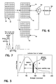
- FIG. 6 is a schematic diagram depicting a frame differencing technique used in the airbag deployment system of the present invention.
- FIG. 7 is a timing diagram for the frame differencing technique of the invention.
- a technique for detecting, identifying and tracking a person in the passenger seat of a vehicle is disclosed.
- the identification and tracking of the person is determined by face recognition software, in particular, software that recognizes and tracks the person's eyes and other facial features. Tracking can take place that way at many head angles and poses.
- the software algorithm would use calibrated face and feature separation to estimate range. The tracking of a localized area on the human face allows more image frames to be acquired per second, permitting more frequent tracking of the person. The more frequent tracking of the facial features will prevent acquiring a blurry image because the image is updated more frequently.
- Various software is known in the art that processes data from video data patterns received from an object being analyzed, and determines whether the object has a face.
- such software includes the Visionics Face-It software, well known to those skilled in the art.
- the present invention is not limited to any particular facial feature mapping function, but can include any known algorithm, suitable for the purposes described herein, for recognizing facial features, whether it be two-dimensional or three-dimensional, that are then also to be used for ranging functions, as well.
- ranging algorithms are used in combination with the know face recognition software.
- the present invention employs infrared radiation reflected off of objects in the passenger side of the passenger compartment of a vehicle that is received by an electronic video camera.
- the video camera generates the electrical signals and image used by the face recognition software to determine the presence identify and tracking of the person.
- FIG. 1 is a cut-away, side, plan view of the passenger side compartment 10 of a vehicle 12 .
- a person 16 is shown in the passenger seat 18 , where the person 16 is moving forward during a crash event.
- An airbag pillow 20 is shown being deployed through an airbag door 24 housed in an instrument panel 22 during the crash event.
- FIG. 2 is a perspective view of the unit 26 removed from the vehicle 12 .
- the unit 26 includes a cluster 28 of IR LEDs 30 .
- a plurality of LEDs 30 is provided to generate the necessary intensity for daylight operation.
- the cluster 28 emits a beam of IR radiation towards the person 16 that is reflected therefrom back towards the unit 26 .
- a video camera 34 is provided in the unit 26 to receive the reflected radiation from the person 16 .
- the video camera 34 is used by way of a non-limiting example in that any detector that detects infrared radiation suitable for the purposes described herein can be used.
- a filter 36 is provided over the camera 34 to filter out radiation that is not within the desirable infrared range.
- the filter 36 can be any filter suitable for the purposes described herein, such as a TiO 2 filter or a polarizing filter.
- the filter layers and thickness can be chosen to transmit the IR image to the detector, but to reflect the visible image away from the detector.
- the polarizing filter can be used to reduce visible light to the detector using electro-optical polarization that passes the IR wavelengths, but strongly attenuates the non-IR wavelengths.
- FIG. 3 shows the luminance curve for sunlight, where the filter 36 passes infrared radiation in the 40 nm bandpass window.
- the filter 36 provides some protection against sunlight that may affect the operation of the airbag deployment system, and recognition of the face of the person 16 .
- a single camera is used to acquire and monitor the range of the person 16 .
- the software employed to perform this function utilizes two separate locations on the occupant's face to provide the ranging. In a preferred embodiment, it is the person's eyes that are detected to provide the triangulation for ranging purposes. However, as will be appreciated by those skilled in the art, other facial features of the person 16 can also be used, such as the person's ears, etc.
- the software algorithm allows the person's head size to be determined so that both eyes do not need to be in view to track the person after he has been acquired. Additionally, the software can be used to view other parts of the person's body, such as the person's torso, in combination with the facial feature or head size detection.
- a database can be used to store specific information, such as eye-to-eye separation, about a person, so that the software can particularly identify that person. This is important, in one example, so that the system can identify children and fifth-percent females, and inhibit air bag firing for these people, as required by government mandated regulations. Also, being able to specifically identify a person improves the ranging accuracy of the system because the system knows that person's eye separation or other specific facial features.
- FIG. 4 is a representation of the camera orientation and position parameters with respect to the center and normal of the airbag door 24 .
- the three parameters that must be estimated in the vehicle for ranging according to the invention after the camera and Visionics Face-It software are calibrated include two position offsets and one angular offset.
- the two position offsets are the lateral offset of the camera 34 with respect to the center of the airbag ( ⁇ Y), measured laterally and perpendicularly to the normal vector out of the center of the airbag door 24 , and the front or back offset ( ⁇ X) of the camera 34 with respect to the center of the airbag door 24 , measured along an axis parallel to the normal out of the center of the airbag door 24 .
- the angular parameter is the azimuth offset ( ⁇ ) between the optical axis of the camera 34 and the normal vector coming out of the center of the airbag 20 . Only two of these parameters, ⁇ X and ⁇ , are used in the modified monocular distance equation.
- a calibration procedure can be used to determine ⁇ Y, ⁇ X and ⁇ .
- calibrating with a large number of points would not require a model for estimating that is described herein.
- the cost of making the large number of measurements necessary for a brute force calibration and the possibility that out of range operation of the camera 34 or software might occur unnoticed with brute force calibration must be considered before using that approach.
- the approach used herein uses a small number of calibration tests in order to form a model for interpolation.
- x - ⁇ ⁇ ⁇ X + ⁇ eye_separation ⁇ _distance tan ⁇ ( ⁇ left_eye + ⁇ ) - tan ⁇ ( ⁇ rt_eye + ⁇ ⁇ ⁇ ⁇ ) ⁇ ( 6 )
- the calibration table consists of a lookup table of the SDK determined eye coordinate as a pixel value linked to the associated ray slope, as viewed in the camera coordinate system. Equation (6) can be simplified in terms of ray slopes (tangents of singular angles), so that the calibration table can be used directly to determine the eye to airbag distance from monocular operation.
- tan ⁇ ( a + b ) tan ⁇ ( a ) + tan ⁇ ( b ) 1 - tan ⁇ ( a ) ⁇ tan ⁇ ( b ) ( 7 ) and applying this identify to equation (6), leaves the modified monocular equation in a form that can be used by direct look up of tangent/slopes from the calibration lookup table. This equation is given in equation (8) below.
- FIG. 5 is a block diagram of an imaging system 50 of the invention including a digital signal processor (DSP) 52 .
- the DSP 52 includes the face recognition software and ranging functions that performs the analysis on the image generated by the camera 34 .
- a clock generator 60 provides timing for the various digital devices in the system 50 , and a power management system 62 provides the power.
- the DSP 52 is connected to a CMOS chip 70 including a pixel array 72 that represents the IR detector, such as the camera 34 .
- the pixel array 72 includes 256 ⁇ 256 pixels to provide the desired level of resolution.
- the CMOS chip 70 also includes various elements for timing and control purposes, including state matching logic 74 , clock/timing circuitry 76 , analog conditioning circuit 78 , registers/buffers 80 , on-chip programmable logic circuitry 82 , etc. Additionally, an analog-to-digital converter 84 is also provided to convert the analog signal from the pixel array 72 to a representative digital signal. An on-chip SRAM memory 86 is shown for storage purposes, but can be off-chip as well. The operation of these devices in the system described herein would be apparent to those skilled in the art.
- the infrared LEDs 30 are continuously on to provide the reflected radiation received by the camera 34 .
- typically some kind of filtering or signal processing must be done to correct for the problems caused by direct sunlight on the camera 34 that make it through the filter 36 .
- the system 50 needs to be able to distinguish between shadows caused by sunlight and actual edges of features on the occupant 16 .
- a frame differencing technique is employed that synchronously pulses the LEDs 30 on for a predetermined period of time and a predetermined number of frames of video data, and then off for a predetermined period of time over the same number of frames of video data.
- the frames of data are subtracted from each other so that the frames without IR illumination can be subtracted from the frames with IR illumination, and the background can be eliminated.
- the detector is electronically shuttered synchronously with the pulses to provide exposure control.
- the frame differencing technique described herein is used in conjunction with the infrared pulsing to achieve the desired result. In other words, the frame differencing is synchronized to the infrared pulses.
- the concept of frame differencing is the time-aperture, pixel-level storage of images using natural illumination only and natural illumination with added infrared illumination. Frame differencing allows these images to be subtracted to mitigate the effects of strong visible illumination.
- the set-up includes a neutral density filter that sets the IR illumination, plus worst case background to maximize analog-to-digital converter input. Face recognition requires that the worst case analog-to-digital range for the differenced image be 5 to 6 bits. The visible light would fit within the remaining range allowed by the analog-to-digital converter.
- the image differencing is either performed in the analog domain, where two pixel level capacitors are charged, one at each illumination level, or in the digital domain where a RAM memory of the digitized pixel output is taken at each illumination.
- the frame differencing acts to subtract out the illumination effects of the visible illumination, and to improve the image contrast.
- the frame differencing function can be performed in the acquisition/high bandwidth generation mode or in the narrow bandwidth track mode using pulsed LED illumination.
- the number of the electrons from the pulsed IR light source must be 10 times greater than the photon noise of the ambient illumination.
- the noise of the ambient illumination is the square root of two times the number of electrons within the sun intensity, because two image frames are being acquired for every one IR image received.
- FIG. 6 is a representation of how the frame differencing is performed in the camera 34 , according to one embodiment of the present invention.
- FIG. 7 is a signal timing line showing the operation of the frame differencing technique of the invention.
- a pixel array 90 in the camera 34 receives radiation from the scene for a predetermined time period (10 ⁇ s) during a pulse of IR from the LEDs 30 . At this time, the pixel array 90 receives ambient light and infrared light. The charge stored by each pixel or photodiode 92 in the array 90 is then transferred to a charge storage site 94 made up of a plurality of capacitors, one capacitor 96 for each pixel 92 .
- the pixel array 90 detects just the ambient light for the same time period.
- the charge received by the pixel array 90 at this time period is stored in a capacitor storage site 98 , having capacitors 100 .
- An electronic shutter is employed in the detector to open and close at the appropriate time synchronously with the pulses of IR radiation for the operation described herein.
- the two storage sites 94 and 98 are summed in a summation amplifier 102 .
- the difference between the two storage sites 94 and 98 is then digitized by an analog-to-digital converter 104 , and represents the frame of data where the ambient light has been removed.
- the readout of data takes about 10 ms, then at the next time period, the next pulse from the cluster 28 occurs.
- the complete frame differencing process can be performed on a single chip in CMOS where the pixel array 90 and the storage sites 94 and 98 are together. In an alternate embodiment, the frame differencing is performed at a different time period at an off-chip site, where the storage sites 94 and 98 are RAM.
- the frame differencing technique of the invention can be described in the following manner.
- the variables are defined as ambient illumination I(x,y), direct ambient illumination T(x,y), scene reflectance R(x,y), and modulated source as L when on, and O when off.
- the response of the camera 34 is proportional to the product of reflectance and illumination.
- L must be much greater than the photon noise on I.
- I is made as small as possible by using a narrow bandpass filter aligned in frequency to L.
- the raw sampling rate has to be twice the requirement set by the object tracking because two frames are differenced to get one frame to supply the face recognition software.
- the LEDs 30 have to be much faster.
- the IR radiation source has to be modulated such that all emission is during the time when all detectors are active. If the integration times of all pixels in the detector are not aligned, the available time for the source to be ON is reduced by the worst case misalignment.
Abstract
Description
x=−ΔX+ρ sin(θ+Δθ)cos(φ+Δφ) (1)
y=−ΔY+ρ sin(θ+Δθ)sin(φ+Δφ) (2)
This assumes that θ+Δθ is fixed during the calibration. Rearranging equations (1) and (2) yields:
Making eye coordinate readout measurements at fixed x+ΔX, and then taking the slope of the tangent with respect to changes in y yields:
Knowing x and the result on the right side of equation (4), ΔX can be determined. Knowing ΔX, equation (3) and the measured data can be used to determine ΔY. Then, using ΔX and ΔY, equation (3) and the data, Δφ can be determined. Using equation (3), and the fact that:
eye_separation_distance=Yrt
the modified monocular equation follows from equation (6) for defining the objective parameter x, or the eye to airbag distance.
and applying this identify to equation (6), leaves the modified monocular equation in a form that can be used by direct look up of tangent/slopes from the calibration lookup table. This equation is given in equation (8) below.
S(x,y,OFF)=k*(I(x,y)*R(x,y))
S*(x,y,ON)=k*((L+I(x,y))*R(x,y))+T(x,y)
D(x,y)=S(x,y,ON)−S(x,y,OFF)=KL*R(x,y)
This difference scene has much smaller dynamic range than the simple image S(x,y,OFF). The same benefit can be derived by reading out the frame with LED, then reading the frame without LED and subtracting the frames external to the
Claims (49)
Priority Applications (5)
| Application Number | Priority Date | Filing Date | Title |
|---|---|---|---|
| US09/607,090 US6904347B1 (en) | 2000-06-29 | 2000-06-29 | Human presence detection, identification and tracking using a facial feature image sensing system for airbag deployment |
| DE60106134T DE60106134T2 (en) | 2000-06-29 | 2001-06-13 | Face pick-up sensor for person recognition, identification and observation for airbag control |
| EP01113565A EP1167126B1 (en) | 2000-06-29 | 2001-06-13 | Human presence detection, identification and tracking using a facial feature image sensing system for airbag deployment |
| KR10-2001-0034419A KR100440669B1 (en) | 2000-06-29 | 2001-06-18 | Human presence detection, identification and tracking using a facial feature image sensing system for airbag deployment |
| JP2001192769A JP4246410B2 (en) | 2000-06-29 | 2001-06-26 | System and method for deploying an air bag by detecting, identifying and tracking the presence of a human using a facial feature image sensing system |
Applications Claiming Priority (1)
| Application Number | Priority Date | Filing Date | Title |
|---|---|---|---|
| US09/607,090 US6904347B1 (en) | 2000-06-29 | 2000-06-29 | Human presence detection, identification and tracking using a facial feature image sensing system for airbag deployment |
Publications (1)
| Publication Number | Publication Date |
|---|---|
| US6904347B1 true US6904347B1 (en) | 2005-06-07 |
Family
ID=24430762
Family Applications (1)
| Application Number | Title | Priority Date | Filing Date |
|---|---|---|---|
| US09/607,090 Expired - Fee Related US6904347B1 (en) | 2000-06-29 | 2000-06-29 | Human presence detection, identification and tracking using a facial feature image sensing system for airbag deployment |
Country Status (5)
| Country | Link |
|---|---|
| US (1) | US6904347B1 (en) |
| EP (1) | EP1167126B1 (en) |
| JP (1) | JP4246410B2 (en) |
| KR (1) | KR100440669B1 (en) |
| DE (1) | DE60106134T2 (en) |
Cited By (14)
| Publication number | Priority date | Publication date | Assignee | Title |
|---|---|---|---|---|
| US20060175807A1 (en) * | 2005-01-06 | 2006-08-10 | Ryan Miller | Method for crash testing a motor vehicle |
| US20070040365A1 (en) * | 2005-08-22 | 2007-02-22 | Calsonic Kansei Corporation | Vehicle data recorder |
| US20070272837A1 (en) * | 2006-05-29 | 2007-11-29 | Honda Motor Co., Ltd. | Vehicle occupant detection device |
| US20090024309A1 (en) * | 2007-07-16 | 2009-01-22 | Crucs Holdings, Llc | System and method for monitoring vehicles on a roadway |
| US20110218650A1 (en) * | 2007-07-16 | 2011-09-08 | Crucs Holdings, Llc | Systems and methods for automatically changing operational states of appliances |
| US20110267186A1 (en) * | 2010-04-29 | 2011-11-03 | Ford Global Technologies, Llc | Occupant Detection |
| US9091775B1 (en) * | 2013-02-04 | 2015-07-28 | Sierra Innotek, Inc. | Method and apparatus for detecting and locating camera illuminators |
| US9446730B1 (en) * | 2015-11-08 | 2016-09-20 | Thunder Power Hong Kong Ltd. | Automatic passenger airbag switch |
| KR20170040692A (en) | 2015-10-05 | 2017-04-13 | (주)감성과학연구센터 | Method for extracting information of facial movement based on Action Unit |
| KR20170040693A (en) | 2015-10-05 | 2017-04-13 | (주)감성과학연구센터 | Method for extracting Emotional Expression information based on Action Unit |
| US10131309B2 (en) | 2016-05-16 | 2018-11-20 | Hyundai Motor Company | Apparatus and method for controlling airbag |
| DE102017010151A1 (en) | 2017-11-02 | 2019-05-02 | Dräger Safety AG & Co. KGaA | Infrared optical gas measuring device |
| CN109815863A (en) * | 2019-01-11 | 2019-05-28 | 北京邮电大学 | Firework detecting method and system based on deep learning and image recognition |
| US20200300997A1 (en) * | 2019-03-19 | 2020-09-24 | Brose Fahrzeugteile Se & Co. Kommanditgesellschaft, Bamberg | Method for detecting a living being on a seat of a vehicle, detection arrangement and vehicle |
Families Citing this family (14)
| Publication number | Priority date | Publication date | Assignee | Title |
|---|---|---|---|---|
| US7110570B1 (en) | 2000-07-21 | 2006-09-19 | Trw Inc. | Application of human facial features recognition to automobile security and convenience |
| US6856694B2 (en) * | 2001-07-10 | 2005-02-15 | Eaton Corporation | Decision enhancement system for a vehicle safety restraint application |
| ES2279938T3 (en) | 2002-02-02 | 2007-09-01 | Qinetiq Limited | HEAD POSITION SENSOR. |
| DE10238223A1 (en) * | 2002-08-21 | 2004-03-04 | Robert Bosch Gmbh | Method and arrangement for the control of irreversible restraint devices depending on the seating position of a person |
| KR100512864B1 (en) * | 2003-02-11 | 2005-09-06 | 현대모비스 주식회사 | Method for controlling an air-bag system in a vehicle and apparatus thereof |
| US6944527B2 (en) * | 2003-11-07 | 2005-09-13 | Eaton Corporation | Decision enhancement system for a vehicle safety restraint application |
| KR100821924B1 (en) * | 2007-04-19 | 2008-04-16 | 주식회사 현대오토넷 | Passenger head detection system and method thereof |
| KR100862052B1 (en) * | 2007-06-05 | 2008-10-09 | 안상호 | Ir video camera apparatus for smart airbag with active type ir-led and ir distance sensor |
| US10277837B2 (en) | 2013-11-05 | 2019-04-30 | Visteon Global Technologies, Inc. | System and method for monitoring a driver of a vehicle |
| US10829072B2 (en) | 2015-04-10 | 2020-11-10 | Robert Bosch Gmbh | Detection of occupant size and pose with a vehicle interior camera |
| JP6825903B2 (en) | 2016-12-27 | 2021-02-03 | 矢崎総業株式会社 | Driver imager |
| FR3079652B1 (en) * | 2018-03-27 | 2020-04-10 | Valeo Comfort And Driving Assistance | DISTANCE EVALUATION METHOD, ASSOCIATED EVALUATION SYSTEM, AND AIR BAG MANAGEMENT SYSTEM |
| IT201800008074A1 (en) * | 2018-08-13 | 2020-02-13 | Italdesign-Giugiaro SPA | Procedure and system for checking the correct deployment of an airbag device. |
| DE102021210334A1 (en) | 2021-09-17 | 2023-03-23 | Robert Bosch Gesellschaft mit beschränkter Haftung | Method for determining operating parameters for a restraint system in a vehicle |
Citations (10)
| Publication number | Priority date | Publication date | Assignee | Title |
|---|---|---|---|---|
| US4648052A (en) | 1983-11-14 | 1987-03-03 | Sentient Systems Technology, Inc. | Eye-tracker communication system |
| US4720189A (en) | 1986-01-07 | 1988-01-19 | Northern Telecom Limited | Eye-position sensor |
| US5446661A (en) * | 1993-04-15 | 1995-08-29 | Automotive Systems Laboratory, Inc. | Adjustable crash discrimination system with occupant position detection |
| US5482314A (en) * | 1994-04-12 | 1996-01-09 | Aerojet General Corporation | Automotive occupant sensor system and method of operation by sensor fusion |
| US5829782A (en) * | 1993-03-31 | 1998-11-03 | Automotive Technologies International, Inc. | Vehicle interior identification and monitoring system |
| US5835613A (en) * | 1992-05-05 | 1998-11-10 | Automotive Technologies International, Inc. | Optical identification and monitoring system using pattern recognition for use with vehicles |
| US5845000A (en) | 1992-05-05 | 1998-12-01 | Automotive Technologies International, Inc. | Optical identification and monitoring system using pattern recognition for use with vehicles |
| USRE36041E (en) | 1990-11-01 | 1999-01-12 | Massachusetts Institute Of Technology | Face recognition system |
| US6037860A (en) * | 1997-09-20 | 2000-03-14 | Volkswagen Ag | Method and arrangement for avoiding and/or minimizing vehicle collisions in road traffic |
| US6060989A (en) | 1998-10-19 | 2000-05-09 | Lucent Technologies Inc. | System and method for preventing automobile accidents |
Family Cites Families (6)
| Publication number | Priority date | Publication date | Assignee | Title |
|---|---|---|---|---|
| JPH01158579A (en) * | 1987-09-09 | 1989-06-21 | Aisin Seiki Co Ltd | Image recognizing device |
| ES2041850T3 (en) * | 1988-06-03 | 1993-12-01 | Inventio Ag | PROCEDURE AND DEVICE FOR CONTROLLING THE POSITION OF AN AUTOMATIC DOOR. |
| DE19645175A1 (en) * | 1996-11-02 | 1998-05-07 | Telefunken Microelectron | Controlling optical monitoring appliance for seat occupancy of vehicle |
| US5737083A (en) * | 1997-02-11 | 1998-04-07 | Delco Electronics Corporation | Multiple-beam optical position sensor for automotive occupant detection |
| US5927752A (en) * | 1997-05-19 | 1999-07-27 | Brandin; Boerje A. | Apparatus and methods for determining seat occupant parameters prior to deployment of an automobile airbag |
| DE19757595C2 (en) * | 1997-12-23 | 2000-05-11 | Siemens Ag | Method and device for recording a three-dimensional distance image |
-
2000
- 2000-06-29 US US09/607,090 patent/US6904347B1/en not_active Expired - Fee Related
-
2001
- 2001-06-13 DE DE60106134T patent/DE60106134T2/en not_active Expired - Lifetime
- 2001-06-13 EP EP01113565A patent/EP1167126B1/en not_active Expired - Lifetime
- 2001-06-18 KR KR10-2001-0034419A patent/KR100440669B1/en not_active IP Right Cessation
- 2001-06-26 JP JP2001192769A patent/JP4246410B2/en not_active Expired - Fee Related
Patent Citations (11)
| Publication number | Priority date | Publication date | Assignee | Title |
|---|---|---|---|---|
| US4648052A (en) | 1983-11-14 | 1987-03-03 | Sentient Systems Technology, Inc. | Eye-tracker communication system |
| US4720189A (en) | 1986-01-07 | 1988-01-19 | Northern Telecom Limited | Eye-position sensor |
| USRE36041E (en) | 1990-11-01 | 1999-01-12 | Massachusetts Institute Of Technology | Face recognition system |
| US5835613A (en) * | 1992-05-05 | 1998-11-10 | Automotive Technologies International, Inc. | Optical identification and monitoring system using pattern recognition for use with vehicles |
| US5845000A (en) | 1992-05-05 | 1998-12-01 | Automotive Technologies International, Inc. | Optical identification and monitoring system using pattern recognition for use with vehicles |
| US5829782A (en) * | 1993-03-31 | 1998-11-03 | Automotive Technologies International, Inc. | Vehicle interior identification and monitoring system |
| US5446661A (en) * | 1993-04-15 | 1995-08-29 | Automotive Systems Laboratory, Inc. | Adjustable crash discrimination system with occupant position detection |
| US5482314A (en) * | 1994-04-12 | 1996-01-09 | Aerojet General Corporation | Automotive occupant sensor system and method of operation by sensor fusion |
| US5890085A (en) * | 1994-04-12 | 1999-03-30 | Robert Bosch Corporation | Methods of occupancy state determination and computer programs |
| US6037860A (en) * | 1997-09-20 | 2000-03-14 | Volkswagen Ag | Method and arrangement for avoiding and/or minimizing vehicle collisions in road traffic |
| US6060989A (en) | 1998-10-19 | 2000-05-09 | Lucent Technologies Inc. | System and method for preventing automobile accidents |
Non-Patent Citations (1)
| Title |
|---|
| J. Krumm, G. Kirk; "Video Occupant Detection for Air Bag Deployment", Sandia Commercially Valuable Information, SAND97-0408, Feb. 1997, pp. 1-20. |
Cited By (25)
| Publication number | Priority date | Publication date | Assignee | Title |
|---|---|---|---|---|
| US20060175807A1 (en) * | 2005-01-06 | 2006-08-10 | Ryan Miller | Method for crash testing a motor vehicle |
| US7912607B2 (en) * | 2005-01-06 | 2011-03-22 | Honda Motor Co., Ltd. | Method for crash testing a motor vehicle |
| US20110209522A1 (en) * | 2005-01-06 | 2011-09-01 | Honda Motor Co., Ltd. | Method For Crash Testing A Motor Vehicle |
| US8682534B2 (en) * | 2005-01-06 | 2014-03-25 | Honda Motor Co., Ltd. | Method for crash testing a motor vehicle |
| US20070040365A1 (en) * | 2005-08-22 | 2007-02-22 | Calsonic Kansei Corporation | Vehicle data recorder |
| US20070272837A1 (en) * | 2006-05-29 | 2007-11-29 | Honda Motor Co., Ltd. | Vehicle occupant detection device |
| US20090024309A1 (en) * | 2007-07-16 | 2009-01-22 | Crucs Holdings, Llc | System and method for monitoring vehicles on a roadway |
| US20110218650A1 (en) * | 2007-07-16 | 2011-09-08 | Crucs Holdings, Llc | Systems and methods for automatically changing operational states of appliances |
| US8868220B2 (en) | 2007-07-16 | 2014-10-21 | Crucs Holdings, Llc | Systems and methods for automatically changing operational states of appliances |
| US9076331B2 (en) | 2007-07-16 | 2015-07-07 | Crucs Holdings, Llc | System and method to monitor vehicles on a roadway and to control driving restrictions of vehicle drivers |
| US20110267186A1 (en) * | 2010-04-29 | 2011-11-03 | Ford Global Technologies, Llc | Occupant Detection |
| US8836491B2 (en) * | 2010-04-29 | 2014-09-16 | Ford Global Technologies, Llc | Occupant detection |
| US9091775B1 (en) * | 2013-02-04 | 2015-07-28 | Sierra Innotek, Inc. | Method and apparatus for detecting and locating camera illuminators |
| KR20170040692A (en) | 2015-10-05 | 2017-04-13 | (주)감성과학연구센터 | Method for extracting information of facial movement based on Action Unit |
| KR20170040693A (en) | 2015-10-05 | 2017-04-13 | (주)감성과학연구센터 | Method for extracting Emotional Expression information based on Action Unit |
| US9446730B1 (en) * | 2015-11-08 | 2016-09-20 | Thunder Power Hong Kong Ltd. | Automatic passenger airbag switch |
| US9725061B2 (en) * | 2015-11-08 | 2017-08-08 | Thunder Power New Energy Vehicle Development Company Limited | Automatic passenger airbag switch |
| US10358104B2 (en) | 2015-11-08 | 2019-07-23 | Thunder Power New Energy Vehicle Development Company Limited | Automated passenger airbag switch |
| US10131309B2 (en) | 2016-05-16 | 2018-11-20 | Hyundai Motor Company | Apparatus and method for controlling airbag |
| DE102017010151A1 (en) | 2017-11-02 | 2019-05-02 | Dräger Safety AG & Co. KGaA | Infrared optical gas measuring device |
| US11054366B2 (en) | 2017-11-02 | 2021-07-06 | Dräger Safety AG & Co. KGaA | Infrared optical gas-measuring device |
| CN109815863A (en) * | 2019-01-11 | 2019-05-28 | 北京邮电大学 | Firework detecting method and system based on deep learning and image recognition |
| CN109815863B (en) * | 2019-01-11 | 2021-10-12 | 北京邮电大学 | Smoke and fire detection method and system based on deep learning and image recognition |
| US20200300997A1 (en) * | 2019-03-19 | 2020-09-24 | Brose Fahrzeugteile Se & Co. Kommanditgesellschaft, Bamberg | Method for detecting a living being on a seat of a vehicle, detection arrangement and vehicle |
| US11709242B2 (en) * | 2019-03-19 | 2023-07-25 | Brose Fahrzeugteile Se & Co. Kommanditgesellschaft, Bamberg | Method for detecting a living being on a seat of a vehicle, detection arrangement and vehicle |
Also Published As
| Publication number | Publication date |
|---|---|
| JP2002037015A (en) | 2002-02-06 |
| JP4246410B2 (en) | 2009-04-02 |
| DE60106134T2 (en) | 2005-10-20 |
| DE60106134D1 (en) | 2004-11-11 |
| KR20020002220A (en) | 2002-01-09 |
| EP1167126A3 (en) | 2003-05-02 |
| EP1167126A2 (en) | 2002-01-02 |
| EP1167126B1 (en) | 2004-10-06 |
| KR100440669B1 (en) | 2004-07-19 |
Similar Documents
| Publication | Publication Date | Title |
|---|---|---|
| US6810135B1 (en) | Optimized human presence detection through elimination of background interference | |
| US6904347B1 (en) | Human presence detection, identification and tracking using a facial feature image sensing system for airbag deployment | |
| US7110570B1 (en) | Application of human facial features recognition to automobile security and convenience | |
| US6724920B1 (en) | Application of human facial features recognition to automobile safety | |
| EP1816589B1 (en) | Detection device of vehicle interior condition | |
| US11935248B2 (en) | System, device, and methods for detecting and obtaining information on objects in a vehicle | |
| US20040153229A1 (en) | System and method for providing intelligent airbag deployment | |
| US6373557B1 (en) | Method and apparatus for picking up a three-dimensional range image | |
| US7319777B2 (en) | Image analysis apparatus | |
| US20060133653A1 (en) | Security identification system and method | |
| EP1043682A1 (en) | Holographic object position and type sensing system and method | |
| JP2004261598A (en) | Device and method for detecting pupil | |
| WO2021005603A1 (en) | Systems, devices and methods for measuring the mass of objects in a vehicle | |
| GB2374228A (en) | A collision warning device | |
| EP3701603B1 (en) | Vcsel based biometric identification device | |
| Conde et al. | A smart airbag solution based on a high speed CMOS camera system | |
| Klomark | Occupant detection using computer vision | |
| WO2007138025A1 (en) | Electro-optical device for counting persons, or other, based on processing three-dimensional images, and relative method | |
| Federspiel | Emerging CCD-CMOS Technology: An Opportunity for Advanced in Vehicle Safety Sensors | |
| KR20220160168A (en) | Face Identification Heat Detection and Tracking System with multiple cameras | |
| Boverie et al. | SIEMENS ZT KM3 |
Legal Events
| Date | Code | Title | Description |
|---|---|---|---|
| AS | Assignment |
Owner name: TRW INC., CALIFORNIA Free format text: ASSIGNMENT OF ASSIGNORS INTEREST;ASSIGNORS:BERENZ, JOHN J.;MCIVER, GEORG W.;NIESEN, JOSEPH W.;AND OTHERS;REEL/FRAME:010918/0766;SIGNING DATES FROM 20000628 TO 20000629 |
|
| AS | Assignment |
Owner name: TRW INC., CALIFORNIA Free format text: CORRECTIVE ASSIGNMENT TO CORRECT THE NAME OF CONVEYING PARTY "GEORG W. MCIVER" PREVIOUSLY RECORDED ON REEL 010918, FRAME 0766;ASSIGNORS:BERENZ, JOHN J.;MCIVER, GEORGE W.;NIESEN, JOSEPH W.;AND OTHERS;REEL/FRAME:011203/0972;SIGNING DATES FROM 20000628 TO 20000629 |
|
| AS | Assignment |
Owner name: JPMORGAN CHASE BANK, NEW YORK Free format text: THE US GUARANTEE AND COLLATERAL AGREEMENT;ASSIGNOR:TRW AUTOMOTIVE U.S. LLC;REEL/FRAME:014022/0720 Effective date: 20030228 |
|
| FPAY | Fee payment |
Year of fee payment: 4 |
|
| REMI | Maintenance fee reminder mailed | ||
| LAPS | Lapse for failure to pay maintenance fees | ||
| STCH | Information on status: patent discontinuation |
Free format text: PATENT EXPIRED DUE TO NONPAYMENT OF MAINTENANCE FEES UNDER 37 CFR 1.362 |
|
| FP | Lapsed due to failure to pay maintenance fee |
Effective date: 20130607 |