US6910548B2 - Modular speaker construction - Google Patents
Modular speaker construction Download PDFInfo
- Publication number
- US6910548B2 US6910548B2 US10/403,529 US40352903A US6910548B2 US 6910548 B2 US6910548 B2 US 6910548B2 US 40352903 A US40352903 A US 40352903A US 6910548 B2 US6910548 B2 US 6910548B2
- Authority
- US
- United States
- Prior art keywords
- housing
- corner
- inner spline
- panel
- spline
- Prior art date
- Legal status (The legal status is an assumption and is not a legal conclusion. Google has not performed a legal analysis and makes no representation as to the accuracy of the status listed.)
- Expired - Lifetime, expires
Links
Images


Classifications
-
- H—ELECTRICITY
- H04—ELECTRIC COMMUNICATION TECHNIQUE
- H04R—LOUDSPEAKERS, MICROPHONES, GRAMOPHONE PICK-UPS OR LIKE ACOUSTIC ELECTROMECHANICAL TRANSDUCERS; DEAF-AID SETS; PUBLIC ADDRESS SYSTEMS
- H04R1/00—Details of transducers, loudspeakers or microphones
- H04R1/02—Casings; Cabinets ; Supports therefor; Mountings therein
Definitions
- the present invention relates generally to a loudspeaker cabinet, more particularly, the invention relates to a speaker cabinet useful for professional audio equipment that allows for disassembly, servicing and reconfiguration of the speaker as well as ease of mounting.
- Traditional speaker cabinets are generally constructed from six panels (two side panels, a top and a bottom panel, and a front grill and rear panel), such as wooden panels, connected together to form a structural box within which the speaker components are located.
- disassembly for repair, replacement or reconfiguration of the speaker components is cumbersome, if possible at all. Indeed, damage or destruction of the panels is often the case when speaker disassembly is attempted.
- 5,218,176 which, according to the inventor, provides unique acoustical and structural properties and which consists of a porous inner core of rigid urethane foam bonded to fiberglass rovings by means of polyester resin and resin tie blocks. Clearly therefore, the Meyer, Jr. construction does not facilitate ease of disassembly or reconfiguration.
- the present invention provides a speaker housing which comprises a unitary housing skeleton.
- the unitary housing skeleton includes a plurality of corner elements as well as plurality of cross supports. At least one of the pluralities of cross supports extends between two adjacent corner elements to form a speaker housing skeleton.
- the inventive speaker housing skeleton comprises four corner elements or units with cross supports extending between each of the corner elements to thereby define a speaker housing skeleton having top, bottom, front, back, left and right sides.
- Top, bottom, left and right side housing panels can then be attached to the corner elements and front and rear screens or panels (sometimes also referred to as grills or baffles) also attached to the corner elements, in order to form the speaker housing.
- Mounting tabs, for further securing the front and rear panels to the cross supports, are provided to provide for the assembly and disassembly of the speaker and removal and/or interchange of speaker components.
- the corner elements contain integrated slots to facilitate insertion of housing panels, fittings for mounting of front and rear baffles or panels, and external mounting channels for mounting of the speaker.
- Another object of the present invention is the provision of a speaker assembly having a unitary housing framework or skeleton which provides sufficient structural strength to support the external loads placed upon the housing assembly so that side panels are not required to provide structural strength.
- Another object of the present invention is the provision of a speaker housing providing access to the internal components of the speaker for ease of manufacture, maintenance and reconfiguration.
- Still another object of the invention is the provision of a family of speakers having interchangeable components.
- a housing for a loudspeaker which has two side panels, a top panel, a bottom panel, a front panel and a back panel, and which includes a plurality of corner units typically four corner units: two top units and two bottom units), each of the corner units having a first end and a second end and comprising a first inner spline extending therefrom and a second inner spline extending therefrom, the first and second inner splines defining planes offset from each other by an angle of from about 75° and about 105°; and a first outer spline extending therefrom and running generally parallel to the first inner spline and a second outer spline extending therefrom and running generally parallel to the second inner spline, wherein the first inner spline and the first outer spline cooperate to form a first slot sized to receive a top panel or a bottom panel and the second inner spline and the second outer spline
- the inventive corner units further have a fitting at each end thereof, each fitting sized to receive a mounting element for one of the front and back panels.
- the corner units further include at least one (and preferably two) mounting channel(s) extending along the length thereof; when two mounting channels are present, they each defining a plane extending generally orthogonal to each other.
- the inventive speaker housing further comprises a cross support extending between the first inner spline of a first bottom corner unit and the first inner spline of a first top corner unit; a cross support extending between the first inner spline of a second bottom corner unit and the first inner spline of a second top corner unit; a cross support extending from the second inner spline of a first top corner unit and the second inner spline of the second top corner unit; and a cross support extending from the second inner spline of a first bottom corner unit and the second inner spline of the second bottom corner unit.
- the corner units and cross supports combine to form a housing skeleton.
- Two side panels, a top panel and a bottom panel are each engaged in the slots formed by the inner and outer splines of the corner units.
- a front panel (which can be a baffle, grill or screen) is attached to the housing skeleton by a mounting element engaged by the fittings at the front end of the corner units.
- a back panel is attached to the housing skeleton by a mounting element engaged by the fittings at the back end of the corner units.
- FIG. 1 is an exploded view of a speaker housing in accordance with the present invention.
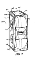
- FIG. 2 is a front perspective view of a speaker housing in accordance with the present invention.
- FIG. 3 is a rear elevation view of the speaker housing of FIG. 2 .
- FIG. 4 is a side elevation view of the speaker housing of FIG. 2 .
- FIG. 5 is a rear perspective view of a speaker housing skeleton in accordance with the present invention.
- FIG. 6 is a perspective view of an alternate embodiment of one of the corner units in accordance with the present invention.
- FIG. 7 is a front plan view of the speaker housing skeleton of FIG. 5 .
- FIG. 8 is a side plan view of the speaker housing skeleton of FIG. 7 .
- FIG. 9 is a bottom plan view of the speaker housing skeleton of FIG. 7 .
- FIG. 10 is a plan view of one of the corner units in accordance with the present invention.
- FIG. 11 is a front perspective view of an alternate embodiment of a speaker housing in accordance with the present invention.
- Housing skeleton 10 comprises a plurality of corner units (also sometimes referred to as corner elements) 20 .
- speaker housing 10 comprises four corner units 20 , one for each of the two top corners of speaker housing skeleton 10 and one for each of the two bottom corners of speaker housing skeleton 10 .
- corner units 20 A and 20 B comprise the upper corners of housing skeleton 10
- corner units 20 C and 20 D comprise the lower corners of housing skeleton 10 .
- FIGS. 2-4 This description is written generally in terms of the speaker configuration shown in FIGS. 2-4 , that is, a generally rectangular speaker; it will be recognized, however, that other speaker configurations, such as that illustrated in FIG. 11 , can also be provided using the speaker housing skeleton 10 concepts taught herein.
- Corner units 20 can be formed of aluminum or other like metal, plastic resins or the like and can be formed by extruding, casting, machining or other like processes familiar to the artisan. Although, as illustrated in FIG. 10 , corner units 20 assume a rounded orientation at 21 A, in fact portion 21 A can be a right angle or other shape as desired.
- corner units 20 each comprise first and second inner arms or splines 22 A and 22 B extending therefrom in different directions.
- First and second inner splines 22 A and 22 B each define a plane which is offset with respect to each other by an angle which can range from about 75° to about 105°; most preferably, inner splines 22 A and 22 B extend from corner units 20 at substantially right angles with respect to each other.
- Corner units 20 further comprise first and second outer arms or splines 24 A and 24 B, which are oriented with respect to inner splines 22 A and 22 B so as run generally parallel thereto and to form a pair of slots running the length of corner units 20 .
- a first slot is formed between splines 22 A and 24 A and a second slot is formed between splines 22 B and 24 B.
- the slots formed between inner splines 22 A and 22 B and outer splines 24 A and 24 B extend in planes offset from each other by an angle of between about 75° and 105°; most preferably, the two slots are orthogonal to each other.
- the slot formed between arms 22 A and 24 A can be referred to as a horizontal slot and the slot formed between arms 22 B and 24 B can be referred to as a vertical slot.
- Corner units 20 further comprises a fitting 26 which can be used for the mounting of a screen, baffle or other front or rear panel of a speaker housing thereto via a screw, rivet, bolt or other like attachment element.
- corner element 20 has a front fitting 26 A at a front end thereof and a rear fitting 26 B at the other end thereof for the attachment of one or more of panels, baffles, grills, screens, etc. to the front and back of speaker housing skeleton 10 , respectively.
- corner units 120 can comprise a fitting 126 which extends the length of corner element 120 and be used for the attachment of front and back panels, etc. in that manner.
- corner units 20 further have formed therein at least one channel 28 , and more preferably, two channels, 28 A and 28 B, as illustrated in FIGS. 5 and 7 .
- Channels 28 A and 28 B are formed to have a cross sectional profile which adopts standard cargo-style locking track dimensions which are an accepted aerospace industry standard and which are commonly used in the speaker rigging hardware industry.
- Channels 28 A and 28 B can be formed into corner units 20 during the extrusion or other formation process or they can be milled into units 20 after formation.
- a plurality of circular hardware attachment points can then be machined into the exterior of channels 28 A and 28 B in any desired location which can be tailored to each specific speaker housings rigging requirements or which can be equally spaced along the entire length of channels 28 A and 28 B. Exemplary of such circular hardware attachment points are illustrated as 228 A and 228 B in FIG. 8 .
- speaker housing skeleton 10 further comprises a plurality of cross supports 30 , which can be denoted as horizontal cross supports 30 A and vertical cross supports 30 B.
- Horizontal cross supports 30 A extend between inner spline 22 A in one of corner units 20 and inner spline 22 A of a horizontally adjacent corner unit 20
- vertical cross supports 30 B extend between inner spline 22 B of one corner unit 20 and inner spline 22 B of a vertically adjacent corner unit 20 .
- cross supports 30 A and 30 B extend between corner units 20 at both the front end and back end of corner units 20 .
- cross supports 30 A, 30 B are attached to inner splines 22 A, 22 B respectively either by welding, by mounting elements such as screws, bolts, rivets, etc. or by any other manner which will reliably secure cross supports 30 A, 30 B to inner splines 22 A, 22 B.
- Additional supports, such as mid-length supports 30 C can also be employed, if desired.
- the horizontal cross supports 30 A can be provided as an integral unit at both the top and bottom of speaker housing skeleton 10 ; likewise, the vertical cross supports 30 B can also be provided as an integral unit at both the left and right sides of speaker housing skeleton 10 . In this way, the structural strength of speaker housing skeleton 10 is even further improved.
- side panels 42 can be engaged in the vertical slots of corner units 20
- top and bottom panels 44 can be engaged in the horizontal slots of corner units 20 .
- These side, top and bottom panels 42 , 44 can be formed of wood, nomex, composites of honeycomb or other materials suitable for acoustic requirements.
- Side, top and bottom panels 42 , 44 may have edges which are thinned for receipt in vertical and horizontal slots, however, that is not necessarily the case.
- Front and rear panels 46 and 48 can then be mounted to fittings 26 and thus held in place to form the front and rear of speaker housing 100 .
- front and rear panels 46 and 48 when secured into place, can also function to hold side panels and top and bottom panels 42 , 44 in place in the horizontal and vertical slots formed in corner units 20 .
- side and top and bottom panels 42 , 44 can be glued in place in the horizontal and vertical slots formed in corner units 20 .
- speaker housing 100 is assembled by placing each of the side panels and top panels 42 , 44 within the horizontal and vertical slots formed in corner units 20 , and then securing the front and rear panels 46 , 48 to corner units 20 with screws, bolts or the like extending into fittings 26 .
- Cross supports 30 are preferably formed from strips of aluminum or other metal having a thickness substantially equal to the thickness of inner splines 22 . Most preferably, cross supports 30 are formed of the same material as is used to form corner units 20 . Cross supports 30 are butted up against the butt ends of inner splines arms 22 and are welded or otherwise joined by conventional techniques. The lines or abutment or weld are finished as smoothly as possible to permit easy access of panels 42 , 44 into the slots formed in corner units 20 .
- Cross supports 30 are designed to be of the thickness compliant with the requirements of load bearing and therefore are generally equal to the thickness to the inner splines 22 of corner units 20 .
- cross supports 30 can be constructed from ⁇ fraction (3/16) ⁇ -inch thick 6061 aluminum alloy.
- a plurality of mounting tabs denoted 50 can be attached, such as by welding, to cross supports 30 .
- Each of mounting tabs 50 has a mounting element, such as a bolt hull 52 or similar mounting element defined therein which can be used for further attachment of front and rear panels 46 , 48 , or of speaker components, such as those illustrated (but not all of which are numbered) in FIG. 1 .
- a speaker housing 100 utilizing the speaker housing skeleton 10 of the present invention is generally manufactured and assembled in the following manner.
- Four corner units 20 are prepared as described hereinabove.
- Cross supports 30 are welded between corner units 20 such that each cross support 30 spans between two corner units 20 and is welded thereto.
- the cross supports 30 and corner units 20 form a unitary structural framework as shown in FIG. 5 .
- top, bottom, left side and right side housing panels 42 , 44 are slid into the slots formed in corner units 20 .
- Panels 42 , 44 and/or the slots may first be coated with glue or other adhesive to promote adhesion.
- Front and back panels 46 , 48 are then detachably attached to speaker housing skeleton 20 by screw, bolts, or other attachment devices which engage fittings 26 .
- the speaker system 200 includes handles 201 , some of which is received in a handle pocket 202 which is mounted in a side panel 42 .
- internal components may include components such as internal port flares, as well as horn perforations, which may also be described as perforated acoustic filters.
- a horn bell can be received through the central most opening of the front panel 46 .
- a horn bell can be attached to horn throat.
- a typical speaker configuration is shown in FIG. 1 .
- a connector plate 210 can be mounted in the rear panel.
- speaker system 200 will recognize that a variety of configurations and components are possible for speaker system 200 .
- Speaker housing 100 provides several major benefits to the overall design philosophy of a speaker system. First, it provides a sufficiently strong structure to meet or exceed the load bearing requirements of the speaker assembly without relying on any of the side, top or bottom panels or other components for additional structural strength. Secondly, it provides a manufacturing jig for complete assembly of the rest of the speaker's components, including providing a gluing jig for the four side, top and bottom panels. Rubber gaskets may also be provided to provide a seal between the front and rear baffles and skeleton 20 . The completed assembly is serviceable and upgradeable due to the nature of this construction methodology which allows the front and rear panels to be removed to access and replace or service internal components.
Abstract
Description
Claims (23)
Priority Applications (3)
| Application Number | Priority Date | Filing Date | Title |
|---|---|---|---|
| US10/403,529 US6910548B2 (en) | 2002-04-05 | 2003-03-31 | Modular speaker construction |
| AU2003226212A AU2003226212A1 (en) | 2002-04-05 | 2003-04-02 | Modular speaker construction |
| PCT/US2003/010125 WO2003086149A2 (en) | 2002-04-05 | 2003-04-02 | Modular speaker construction |
Applications Claiming Priority (3)
| Application Number | Priority Date | Filing Date | Title |
|---|---|---|---|
| US37026702P | 2002-04-05 | 2002-04-05 | |
| US41612102P | 2002-10-04 | 2002-10-04 | |
| US10/403,529 US6910548B2 (en) | 2002-04-05 | 2003-03-31 | Modular speaker construction |
Publications (2)
| Publication Number | Publication Date |
|---|---|
| US20030213642A1 US20030213642A1 (en) | 2003-11-20 |
| US6910548B2 true US6910548B2 (en) | 2005-06-28 |
Family
ID=29424504
Family Applications (1)
| Application Number | Title | Priority Date | Filing Date |
|---|---|---|---|
| US10/403,529 Expired - Lifetime US6910548B2 (en) | 2002-04-05 | 2003-03-31 | Modular speaker construction |
Country Status (3)
| Country | Link |
|---|---|
| US (1) | US6910548B2 (en) |
| AU (1) | AU2003226212A1 (en) |
| WO (1) | WO2003086149A2 (en) |
Cited By (14)
| Publication number | Priority date | Publication date | Assignee | Title |
|---|---|---|---|---|
| US20040238268A1 (en) * | 2003-03-13 | 2004-12-02 | Danley Thomas J. | Sound reproducing apparatus and method for optimizing same |
| US20090022354A1 (en) * | 2007-07-18 | 2009-01-22 | Parker Gary M | Articulated speaker rigging system and method |
| USD735168S1 (en) * | 2013-12-10 | 2015-07-28 | Fugoo Corporation | Jacket for portable speaker |
| USD736745S1 (en) * | 2013-12-10 | 2015-08-18 | Fugoo Corporation | Jacket for portable speaker |
| USD736746S1 (en) * | 2013-12-10 | 2015-08-18 | Fugoo Corporation | Jacket for a portable speaker |
| USD736747S1 (en) * | 2013-12-10 | 2015-08-18 | Fugoo Corporation | Jacket for a portable speaker |
| USD752558S1 (en) | 2015-01-02 | 2016-03-29 | Fugoo Corporation | Jacket for speaker |
| USD753093S1 (en) | 2013-12-10 | 2016-04-05 | Fugoo Corporation | Portable speaker |
| USD763232S1 (en) * | 2014-11-14 | 2016-08-09 | Bose Corporation | Stand |
| US20160234583A1 (en) * | 2015-02-10 | 2016-08-11 | Bose Corporation | Speaker |
| USD772847S1 (en) | 2015-06-15 | 2016-11-29 | David Barrie Manton | Loudspeaker holder |
| USD777150S1 (en) | 2014-11-25 | 2017-01-24 | David Barrie Manton | Loudspeaker holder |
| US9641921B2 (en) | 2014-01-03 | 2017-05-02 | Fugoo Corporation | Speaker core with removable jacket |
| US9794679B2 (en) | 2014-02-14 | 2017-10-17 | Sonic Blocks, Inc. | Modular quick-connect A/V system and methods thereof |
Families Citing this family (12)
| Publication number | Priority date | Publication date | Assignee | Title |
|---|---|---|---|---|
| US7825986B2 (en) | 2004-12-30 | 2010-11-02 | Mondo Systems, Inc. | Integrated multimedia signal processing system using centralized processing of signals and other peripheral device |
| US8880205B2 (en) | 2004-12-30 | 2014-11-04 | Mondo Systems, Inc. | Integrated multimedia signal processing system using centralized processing of signals |
| US7653447B2 (en) | 2004-12-30 | 2010-01-26 | Mondo Systems, Inc. | Integrated audio video signal processing system using centralized processing of signals |
| US8015590B2 (en) | 2004-12-30 | 2011-09-06 | Mondo Systems, Inc. | Integrated multimedia signal processing system using centralized processing of signals |
| US20070076912A1 (en) * | 2005-09-30 | 2007-04-05 | Griffiths Richard D | Audio speaker enclosures |
| US7967104B2 (en) * | 2009-07-03 | 2011-06-28 | Keith Carter | Shippable speaker box |
| US20110000739A1 (en) * | 2009-07-03 | 2011-01-06 | Keith Carter | Shippable speaker box |
| CZ305280B6 (en) * | 2013-08-20 | 2015-07-15 | Martin Olejár | Modular baffle of loudspeaker system |
| US10134295B2 (en) | 2013-09-20 | 2018-11-20 | Bose Corporation | Audio demonstration kit |
| US9997081B2 (en) | 2013-09-20 | 2018-06-12 | Bose Corporation | Audio demonstration kit |
| TWI568276B (en) * | 2014-01-06 | 2017-01-21 | 緯創資通股份有限公司 | Loudspeaker module and thin electronic device haing the same |
| US10645484B2 (en) | 2016-12-23 | 2020-05-05 | Tadeusz Kwolek | Loudspeaker cabinets, systems, and methods of construction |
Citations (12)
| Publication number | Priority date | Publication date | Assignee | Title |
|---|---|---|---|---|
| US1828088A (en) | 1928-10-08 | 1931-10-20 | Benjamin F Lyons | Container construction |
| US4139734A (en) | 1977-04-13 | 1979-02-13 | Kef Electronics Limited | Pivoted loudspeaker enclosure with visual indicator of optimum listening position |
| US4284168A (en) | 1977-08-25 | 1981-08-18 | Braun Aktiengesellschaft | Loudspeaker enclosure |
| US4811403A (en) | 1987-06-10 | 1989-03-07 | U.S. Sound, Inc. | Ultralight loudspeaker enclosures |
| US5218176A (en) * | 1992-04-09 | 1993-06-08 | Meyer Jr Kurt K | Custom featherlight musical speaker enclosures |
| US5627350A (en) | 1995-12-07 | 1997-05-06 | Kang; Shih-Chang | Speaker housing combination |
| US5979591A (en) | 1998-10-06 | 1999-11-09 | Harrison; James B. | Collapsible portable speaker enclosure |
| US5996728A (en) | 1999-04-13 | 1999-12-07 | Eastern Acoustic Works, Inc. | Modular speaker cabinet including an integral rigging system |
| US6035962A (en) | 1999-02-24 | 2000-03-14 | Lin; Chih-Hsiung | Easily-combinable and movable speaker case |
| US6425456B1 (en) | 2000-07-12 | 2002-07-30 | Vector Transworld Corporation | Hollow semicircularly curved loudspeaker enclosure |
| US6513624B2 (en) | 2000-02-03 | 2003-02-04 | C. Ronald Coffin | Loudspeaker enclosure |
| US6571909B1 (en) | 2001-08-31 | 2003-06-03 | Jeffrey Olinger | Loudspeaker enclosure |
-
2003
- 2003-03-31 US US10/403,529 patent/US6910548B2/en not_active Expired - Lifetime
- 2003-04-02 WO PCT/US2003/010125 patent/WO2003086149A2/en not_active Application Discontinuation
- 2003-04-02 AU AU2003226212A patent/AU2003226212A1/en not_active Abandoned
Patent Citations (12)
| Publication number | Priority date | Publication date | Assignee | Title |
|---|---|---|---|---|
| US1828088A (en) | 1928-10-08 | 1931-10-20 | Benjamin F Lyons | Container construction |
| US4139734A (en) | 1977-04-13 | 1979-02-13 | Kef Electronics Limited | Pivoted loudspeaker enclosure with visual indicator of optimum listening position |
| US4284168A (en) | 1977-08-25 | 1981-08-18 | Braun Aktiengesellschaft | Loudspeaker enclosure |
| US4811403A (en) | 1987-06-10 | 1989-03-07 | U.S. Sound, Inc. | Ultralight loudspeaker enclosures |
| US5218176A (en) * | 1992-04-09 | 1993-06-08 | Meyer Jr Kurt K | Custom featherlight musical speaker enclosures |
| US5627350A (en) | 1995-12-07 | 1997-05-06 | Kang; Shih-Chang | Speaker housing combination |
| US5979591A (en) | 1998-10-06 | 1999-11-09 | Harrison; James B. | Collapsible portable speaker enclosure |
| US6035962A (en) | 1999-02-24 | 2000-03-14 | Lin; Chih-Hsiung | Easily-combinable and movable speaker case |
| US5996728A (en) | 1999-04-13 | 1999-12-07 | Eastern Acoustic Works, Inc. | Modular speaker cabinet including an integral rigging system |
| US6513624B2 (en) | 2000-02-03 | 2003-02-04 | C. Ronald Coffin | Loudspeaker enclosure |
| US6425456B1 (en) | 2000-07-12 | 2002-07-30 | Vector Transworld Corporation | Hollow semicircularly curved loudspeaker enclosure |
| US6571909B1 (en) | 2001-08-31 | 2003-06-03 | Jeffrey Olinger | Loudspeaker enclosure |
Cited By (24)
| Publication number | Priority date | Publication date | Assignee | Title |
|---|---|---|---|---|
| US20040238268A1 (en) * | 2003-03-13 | 2004-12-02 | Danley Thomas J. | Sound reproducing apparatus and method for optimizing same |
| US20090022354A1 (en) * | 2007-07-18 | 2009-01-22 | Parker Gary M | Articulated speaker rigging system and method |
| US8126184B2 (en) | 2007-07-18 | 2012-02-28 | Parker Gary M | Articulated speaker rigging system and method |
| USD735168S1 (en) * | 2013-12-10 | 2015-07-28 | Fugoo Corporation | Jacket for portable speaker |
| USD736745S1 (en) * | 2013-12-10 | 2015-08-18 | Fugoo Corporation | Jacket for portable speaker |
| USD736746S1 (en) * | 2013-12-10 | 2015-08-18 | Fugoo Corporation | Jacket for a portable speaker |
| USD736747S1 (en) * | 2013-12-10 | 2015-08-18 | Fugoo Corporation | Jacket for a portable speaker |
| USD821358S1 (en) | 2013-12-10 | 2018-06-26 | Fugoo Corporation | Portable speaker |
| USD753093S1 (en) | 2013-12-10 | 2016-04-05 | Fugoo Corporation | Portable speaker |
| USD777146S1 (en) | 2013-12-10 | 2017-01-24 | Fugoo Corporation | Jacket for portable speaker |
| USD777709S1 (en) | 2013-12-10 | 2017-01-31 | Fugoo Corporation | Jacket for a portable speaker |
| USD766219S1 (en) | 2013-12-10 | 2016-09-13 | Fugoo Corporation | Jacket for a portable speaker |
| USD777147S1 (en) | 2013-12-10 | 2017-01-24 | Fugoo Corporation | Jacket for a portable speaker |
| US9641921B2 (en) | 2014-01-03 | 2017-05-02 | Fugoo Corporation | Speaker core with removable jacket |
| US9668039B2 (en) | 2014-01-03 | 2017-05-30 | Fugoo Corporation | Shock absorbent speaker system |
| US9794679B2 (en) | 2014-02-14 | 2017-10-17 | Sonic Blocks, Inc. | Modular quick-connect A/V system and methods thereof |
| US10034079B2 (en) | 2014-02-14 | 2018-07-24 | Sonic Blocks, Inc. | Modular quick-connect A/V system and methods thereof |
| US11381903B2 (en) | 2014-02-14 | 2022-07-05 | Sonic Blocks Inc. | Modular quick-connect A/V system and methods thereof |
| USD763232S1 (en) * | 2014-11-14 | 2016-08-09 | Bose Corporation | Stand |
| USD777150S1 (en) | 2014-11-25 | 2017-01-24 | David Barrie Manton | Loudspeaker holder |
| USD752558S1 (en) | 2015-01-02 | 2016-03-29 | Fugoo Corporation | Jacket for speaker |
| US9503796B2 (en) * | 2015-02-10 | 2016-11-22 | Bose Corporation | Speaker |
| US20160234583A1 (en) * | 2015-02-10 | 2016-08-11 | Bose Corporation | Speaker |
| USD772847S1 (en) | 2015-06-15 | 2016-11-29 | David Barrie Manton | Loudspeaker holder |
Also Published As
| Publication number | Publication date |
|---|---|
| WO2003086149A2 (en) | 2003-10-23 |
| US20030213642A1 (en) | 2003-11-20 |
| WO2003086149A3 (en) | 2004-01-08 |
| AU2003226212A1 (en) | 2003-10-27 |
Similar Documents
| Publication | Publication Date | Title |
|---|---|---|
| US6910548B2 (en) | Modular speaker construction | |
| US4811403A (en) | Ultralight loudspeaker enclosures | |
| US3949827A (en) | Acoustical panel assembly | |
| US6097829A (en) | Fiber-honeycomb-fiber sandwich speaker diaphragm and method | |
| US6299268B1 (en) | Metallic framework equipped with a progressive tightening corner-piece, in particular for an electrical cabinet | |
| US5082083A (en) | Structure wall mounted speaker assembly | |
| WO2013055814A1 (en) | Truss system with integral channels | |
| US8807269B1 (en) | Loudspeaker enclosure | |
| CN109736502B (en) | Double-layer reinforced ceiling and mounting method thereof | |
| US20100288170A1 (en) | Dual-axis folding table | |
| JP2021521386A (en) | Canopy and compressor equipment or generator equipment with such a canopy | |
| KR200493874Y1 (en) | Easily Assembled Mount and Partition | |
| JP4749853B2 (en) | Assembling desk | |
| US20020185945A1 (en) | Modular drawer system | |
| CN218881271U (en) | Sound insulation aluminum veneer curtain wall | |
| JP2003199867A (en) | Support for game equipment | |
| US20050217543A1 (en) | Tool cabinet fixing and supporting structure | |
| JP2003088718A (en) | Filter frame | |
| RU207910U1 (en) | MOBILE CABIN | |
| CN210839936U (en) | Articulated wall rack device | |
| CN210199729U (en) | Infrared touch screen | |
| CN215132307U (en) | Panel clamping structure of medical tower crane | |
| CN108193805A (en) | Separate frame and partitioning system | |
| CN210917807U (en) | Building acoustic celotex board convenient to concatenation | |
| CN212115840U (en) | Corner die-casting case |
Legal Events
| Date | Code | Title | Description |
|---|---|---|---|
| AS | Assignment |
Owner name: GIBSON GUITAR CORP., TENNESSEE Free format text: ASSIGNMENT OF ASSIGNORS INTEREST;ASSIGNOR:POWELL, MARK H.;REEL/FRAME:014340/0173 Effective date: 20030712 |
|
| AS | Assignment |
Owner name: FLEET CAPITAL CORPORATION, NORTH CAROLINA Free format text: SECURITY AGREEMENT;ASSIGNOR:GIBSON GUITAR CORP.;REEL/FRAME:014438/0246 Effective date: 20030715 Owner name: FLEET CAPITAL CORPORATION,NORTH CAROLINA Free format text: SECURITY AGREEMENT;ASSIGNOR:GIBSON GUITAR CORP.;REEL/FRAME:014438/0246 Effective date: 20030715 |
|
| AS | Assignment |
Owner name: FLEET CAPITAL CORPORATION, AS AGENT, NORTH CAROLIN Free format text: ASSIGNMENT OF ASSIGNORS INTEREST;ASSIGNOR:FLEET CAPITAL CORPORATION;REEL/FRAME:015341/0026 Effective date: 20031217 Owner name: FLEET CAPITAL CORPORATION, AS AGENT,NORTH CAROLINA Free format text: ASSIGNMENT OF ASSIGNORS INTEREST;ASSIGNOR:FLEET CAPITAL CORPORATION;REEL/FRAME:015341/0026 Effective date: 20031217 |
|
| AS | Assignment |
Owner name: FLEET CAPITAL CORPORATION, AS AGENT, NORTH CAROLIN Free format text: THIS IS A CORRECTIVE ASSIGNMENT TO CHANGE OF NATURE OF CONVEYANCE FROM "ASSIGNMENT OF ASSIGNOR'S INTEREST;ASSIGNOR:FLEET CAPITAL CORPORATION, A RHODE ISLAND CORPORATION (SUCCESSOR BY MERGER WITH FLEET CAPITAL CORPORATION, A CONNECTICUT CORPORATION, WHICH WAS FORMERLY KNOWN AS SHAWMUT CAPITAL CORPORATION, A CONNECTICUT CORPORATION).;REEL/FRAME:016814/0940 Effective date: 20031217 Owner name: FLEET CAPITAL CORPORATION, AS AGENT,NORTH CAROLINA Free format text: THIS IS A CORRECTIVE ASSIGNMENT TO CHANGE OF NATURE OF CONVEYANCE FROM "ASSIGNMENT OF ASSIGNOR'S INTEREST;ASSIGNOR:FLEET CAPITAL CORPORATION, A RHODE ISLAND CORPORATION (SUCCESSOR BY MERGER WITH FLEET CAPITAL CORPORATION, A CONNECTICUT CORPORATION, WHICH WAS FORMERLY KNOWN AS SHAWMUT CAPITAL CORPORATION, A CONNECT;REEL/FRAME:016814/0940 Effective date: 20031217 |
|
| AS | Assignment |
Owner name: BANK OF AMERICA, N.A., AS AGENT, GEORGIA Free format text: ASSIGNMENT OF SEC. INTEREST;ASSIGNOR:FLEET CAPITAL CORPORATION;REEL/FRAME:016674/0239 Effective date: 20050729 |
|
| AS | Assignment |
Owner name: AMERICAN CAPITAL FINANCIAL SERVICES, INC., A DELAW Free format text: SECURITY AGREEMENT;ASSIGNOR:GIBSON GUITAR CORPORATION, A DELAWARE CORPORATION;REEL/FRAME:016761/0487 Effective date: 20050818 |
|
| AS | Assignment |
Owner name: GIBSON GUITAR CORP.,TENNESSEE Free format text: RELEASE BY SECURED PARTY;ASSIGNOR:BANK OF AMERICA, N.A., AS AGENT;REEL/FRAME:018757/0450 Effective date: 20061229 Owner name: GIBSON GUITAR CORP., TENNESSEE Free format text: RELEASE BY SECURED PARTY;ASSIGNOR:BANK OF AMERICA, N.A., AS AGENT;REEL/FRAME:018757/0450 Effective date: 20061229 |
|
| AS | Assignment |
Owner name: LASALLE BANK NATIONAL ASSOCIATION, AS AGENT, ILLIN Free format text: SECURITY INTEREST;ASSIGNOR:GIBSON GUITAR CORP.;REEL/FRAME:020218/0516 Effective date: 20061229 Owner name: LASALLE BANK NATIONAL ASSOCIATION, AS AGENT,ILLINO Free format text: SECURITY INTEREST;ASSIGNOR:GIBSON GUITAR CORP.;REEL/FRAME:020218/0516 Effective date: 20061229 |
|
| REMI | Maintenance fee reminder mailed | ||
| LAPS | Lapse for failure to pay maintenance fees | ||
| REIN | Reinstatement after maintenance fee payment confirmed | ||
| FP | Lapsed due to failure to pay maintenance fee |
Effective date: 20090628 |
|
| AS | Assignment |
Owner name: BANK OF AMERICA, NATIONAL ASSOCIATION, NORTH CAROL Free format text: MERGER;ASSIGNOR:LASALLE BANK NATIONAL ASSOCIATION;REEL/FRAME:024850/0903 Effective date: 20081017 |
|
| FEPP | Fee payment procedure |
Free format text: PETITION RELATED TO MAINTENANCE FEES GRANTED (ORIGINAL EVENT CODE: PMFG); ENTITY STATUS OF PATENT OWNER: LARGE ENTITY Free format text: PETITION RELATED TO MAINTENANCE FEES FILED (ORIGINAL EVENT CODE: PMFP); ENTITY STATUS OF PATENT OWNER: LARGE ENTITY |
|
| PRDP | Patent reinstated due to the acceptance of a late maintenance fee |
Effective date: 20110325 |
|
| FPAY | Fee payment |
Year of fee payment: 4 |
|
| STCF | Information on status: patent grant |
Free format text: PATENTED CASE |
|
| SULP | Surcharge for late payment | ||
| AS | Assignment |
Owner name: GIBSON GUITAR CORP., TENNESSEE Free format text: RELEASE BY SECURED PARTY;ASSIGNOR:AMERICAN CAPITAL FINANCIAL SERVICES, INC.;REEL/FRAME:026064/0581 Effective date: 20110323 |
|
| AS | Assignment |
Owner name: GIBSON GUITAR CORP., TENNESSEE Free format text: RELEASE BY SECURED PARTY;ASSIGNOR:BANK OF AMERICA, N.A., AS AGENT;REEL/FRAME:026091/0136 Effective date: 20110325 |
|
| AS | Assignment |
Owner name: BANK OF AMERICA, N.A., AS AGENT, ILLINOIS Free format text: SECURITY AGREEMENT;ASSIGNOR:GIBSON GUITAR CORP.;REEL/FRAME:026113/0001 Effective date: 20110325 |
|
| FPAY | Fee payment |
Year of fee payment: 8 |
|
| AS | Assignment |
Owner name: WELLS FARGO BANK, NATIONAL ASSOCIATION AS COLLATER Free format text: SECURITY AGREEMENT;ASSIGNOR:GIBSON BRANDS, INC.;REEL/FRAME:030922/0936 Effective date: 20130731 |
|
| AS | Assignment |
Owner name: GIBSON GUITAR CORP., TENNESSEE Free format text: RELEASE BY SECURED PARTY;ASSIGNOR:BANK OF AMERICA, N.A.;REEL/FRAME:030939/0119 Effective date: 20130731 |
|
| AS | Assignment |
Owner name: BANK OF AMERICA, N.A., AS AGENT, GEORGIA Free format text: SECOND LIEN INTELLECTUAL PROPERTY SECURITY AGREEMENT;ASSIGNORS:GIBSON BRANDS, INC.;GIBSON INTERNATIONAL SALES LLC;GIBSON PRO AUDIO CORP.;AND OTHERS;REEL/FRAME:030954/0682 Effective date: 20130731 Owner name: BANK OF AMERICA, N.A., AS AGENT, GEORGIA Free format text: SECOND LIEN INTELLECTUAL PROPERTY SECURITY AGREEMENT;ASSIGNORS:GIBSON BRANDS, INC.;GIBSON INTERNATIONAL SALES LLC;GIBSON PRO AUDIO CORP.;AND OTHERS;REEL/FRAME:030983/0692 Effective date: 20130731 |
|
| XAS | Not any more in us assignment database |
Free format text: SECOND LIEN INTELLECTUAL PROPERTY SECURITY AGREEMENT;ASSIGNORS:GIBSON BRANDS, INC.;GIBSON INTERNATIONAL SALES LLC;GIBSON PRO AUDIO CORP.;AND OTHERS;REEL/FRAME:030954/0682 |
|
| AS | Assignment |
Owner name: GIBSON BRANDS, INC., TENNESSEE Free format text: CHANGE OF NAME;ASSIGNOR:GIBSON GUITAR CORP.;REEL/FRAME:031029/0942 Effective date: 20130606 |
|
| FPAY | Fee payment |
Year of fee payment: 12 |
|
| AS | Assignment |
Owner name: WILMINGTON TRUST, NATIONAL ASSOCIATION, AS COLLATE Free format text: ASSIGNMENT OF SECURITY INTEREST;ASSIGNOR:WELLS FARGO BANK, NATIONAL ASSOCIATION, AS COLLATERAL AGENT;REEL/FRAME:039687/0055 Effective date: 20160803 |
|
| AS | Assignment |
Owner name: BANK OF AMERICA, N.A., AS AGENT, GEORGIA Free format text: SECOND LIEN INTELLECTUAL PROPERTY SECURITY AGREEMENT;ASSIGNORS:GIBSON BRANDS, INC.;GIBSON INTERNATIONAL SALES LLC;GIBSON PRO AUDIO CORP.;AND OTHERS;REEL/FRAME:041760/0592 Effective date: 20170215 |
|
| AS | Assignment |
Owner name: CORTLAND CAPITAL MARKET SERVICES LLC, ILLINOIS Free format text: SECURITY INTEREST;ASSIGNOR:GIBSON BRANDS, INC.;REEL/FRAME:046239/0247 Effective date: 20180518 |
|
| AS | Assignment |
Owner name: WELLS FARGO BANK, NATIONAL ASSOCIATION, NEW YORK Free format text: SECURITY INTEREST;ASSIGNOR:GIBSON BRANDS, INC.;REEL/FRAME:047384/0215 Effective date: 20181101 |
|
| AS | Assignment |
Owner name: GIBSON BRANDS, INC., TENNESSEE Free format text: RELEASE BY SECURED PARTY;ASSIGNORS:CORTLAND CAPITAL MARKET SERVICES LLC;WILMINGTON TRUST, NATIONAL ASSOCIATION;BANK OF AMERICA, NA;REEL/FRAME:048841/0001 Effective date: 20181004 |
|
| AS | Assignment |
Owner name: GIBSON BRANDS, INC., TENNESSEE Free format text: RELEASE OF SECURITY INTEREST : RECORDED AT REEL/FRAME - 047384/0215;ASSIGNOR:WELLS FARGO BANK, NATIONAL ASSOCIATION;REEL/FRAME:054823/0016 Effective date: 20201221 |
|
| AS | Assignment |
Owner name: JPMORGAN CHASE BANK, N.A., AS COLLATERAL AGENT, ILLINOIS Free format text: GRANT OF SECURITY INTEREST IN PATENT RIGHTS;ASSIGNOR:GIBSON BRANDS, INC.;REEL/FRAME:054839/0217 Effective date: 20201221 |
|
| AS | Assignment |
Owner name: KKR LOAN ADMINISTRATION SERVICES LLC, NEW YORK Free format text: SECURITY INTEREST;ASSIGNOR:GIBSON BRANDS, INC.;REEL/FRAME:061639/0031 Effective date: 20221006 |