US6911016B2 - Guidewire extension system - Google Patents
Guidewire extension system Download PDFInfo
- Publication number
- US6911016B2 US6911016B2 US09/925,881 US92588101A US6911016B2 US 6911016 B2 US6911016 B2 US 6911016B2 US 92588101 A US92588101 A US 92588101A US 6911016 B2 US6911016 B2 US 6911016B2
- Authority
- US
- United States
- Prior art keywords
- wire
- body member
- guidewire
- view
- guidewire system
- Prior art date
- Legal status (The legal status is an assumption and is not a legal conclusion. Google has not performed a legal analysis and makes no representation as to the accuracy of the status listed.)
- Expired - Fee Related
Links
Images


Classifications
-
- A—HUMAN NECESSITIES
- A61—MEDICAL OR VETERINARY SCIENCE; HYGIENE
- A61M—DEVICES FOR INTRODUCING MEDIA INTO, OR ONTO, THE BODY; DEVICES FOR TRANSDUCING BODY MEDIA OR FOR TAKING MEDIA FROM THE BODY; DEVICES FOR PRODUCING OR ENDING SLEEP OR STUPOR
- A61M25/00—Catheters; Hollow probes
- A61M25/01—Introducing, guiding, advancing, emplacing or holding catheters
- A61M25/09—Guide wires
- A61M25/0905—Guide wires extendable, e.g. mechanisms for extension
-
- A—HUMAN NECESSITIES
- A61—MEDICAL OR VETERINARY SCIENCE; HYGIENE
- A61M—DEVICES FOR INTRODUCING MEDIA INTO, OR ONTO, THE BODY; DEVICES FOR TRANSDUCING BODY MEDIA OR FOR TAKING MEDIA FROM THE BODY; DEVICES FOR PRODUCING OR ENDING SLEEP OR STUPOR
- A61M25/00—Catheters; Hollow probes
- A61M25/01—Introducing, guiding, advancing, emplacing or holding catheters
- A61M25/09—Guide wires
- A61M2025/09058—Basic structures of guide wires
- A61M2025/09083—Basic structures of guide wires having a coil around a core
Definitions
- the invention relates generally to guidewires. More particularly, the invention relates to guidewire extension systems.
- Guidewires are currently utilized in a wide variety of medical procedures. In some situations, it would be desirable to provide a guidewire extension system to effectively extend the overall length of the guidewire.
- the invention is directed to guidewires, and in at least some embodiments, to guidewires for use in percutaneous surgical procedures. More particularly, the invention relates to guidewire extension systems.
- a guidewire system in accordance with the invention includes a first wire having a first end and a second wire having a second end which can be selectively coupled to the first end of the first wire.
- FIG. 1 is a partial plan view of a guidewire system in accordance with an exemplary embodiment of the invention
- FIG. 2 is an enlarged plan view having a first end portion of a first wire and a second end portion of a second wire of the guidewire extension system of FIG. 1 ;
- FIG. 3 is an additional plan view of the first end portion of the first wire and the second end portion of the second wire of FIG. 2 showing the struts of the second wire being deflected inward;
- FIG. 4 is an additional plan view of the first end portion of the first wire and the second end portion of the second wire of FIGS. 2 and 3 , the first end portion of the first wire is coupled to the second end portion of the second wire;
- FIG. 5 is a partial perspective view of another exemplary embodiment of a guidewire extension system showing a first end portion of a first wire and a second end portion of a second wire;
- FIG. 6 is a perspective view of the guidewire extension system of FIG. 6 , showing the first and second wire coupled together;
- FIG. 7 is a plan view illustrating a first end portion of a first wire and a second end portion of a second wire which can form a portion of a guidewire extension system in accordance with another exemplary embodiment of the invention
- FIG. 8 is an additional plan view of the first end portion of the first wire and the second end portion of the second wire of FIG. 7 in a partially coupled position;
- FIG. 9 is an additional plan view of the first end portion of the first wire and the second end portion of the second wire of FIGS. 7 and 8 , in which the first end portion of the first wire is coupled to the second end portion of the second wire;
- FIG. 10 is a partial perspective view of another exemplary embodiment of a guidewire extension system showing a first end portion of a first wire and a second end portion of a second wire;
- FIG. 11 is a plan view of a portion of the guidewire system of FIG. 10 ;
- FIG. 12 is an additional plan view of the guidewire system of FIGS. 10 and 11 showing the wires coupled together;
- FIG. 13 is a partial cross sectional view of a portion of a guidewire system having a first wire and a second wire in accordance with yet another embodiment of the invention.
- FIG. 14 is an additional partial cross sectional view of the guidewire system of FIG. 13 , in which the first wire and the second wire are coupled together;
- FIG. 15 is a partial cross sectional view of a portion of a guidewire system having a first wire and a second wire in accordance with yet another embodiment of the invention.
- FIG. 16 is an additional partial cross sectional view of the guidewire system of FIG. 15 , in which the first wire and the second wire are coupled together;
- FIG. 17 is a partial cross sectional view of a portion of a guidewire system having a first wire and a second wire in accordance with yet another embodiment of the invention.
- FIG. 18 is an additional view of the guidewire system of FIG. 17 , in which the first wire and the second wire are coupled together;
- FIG. 19 is a partial cross sectional view of a portion of a guidewire system having a first wire and a second wire in accordance with yet another embodiment of the invention.
- FIG. 20 is an additional view of the guidewire system of FIG. 19 , in which the first wire and the second wire are coupled together;
- FIG. 21 is a partial cross sectional view of a portion of a guidewire system having a first wire and a second wire in accordance with yet another exemplary embodiment of the invention.
- FIG. 22 is an additional view of the guidewire system of FIG. 21 , in which the first wire and the second wire are coupled together;
- FIG. 23 is a partial cross sectional view of a portion of a guidewire system having a first wire and a second wire in accordance with yet another exemplary embodiment of the invention.
- FIG. 24 is an additional view of the guidewire system of FIG. 23 , in which the first wire and the second wire are coupled together;
- FIG. 25 is a partial cross sectional view of a portion of a guidewire extension system having a first wire and a second wire in accordance with yet another exemplary embodiment of the invention.
- FIG. 26 is a partial cross sectional view of the guidewire system of FIG. 25 , wherein the first wire and the second wire are coupled together;
- FIG. 27 is a partial cross sectional view of a portion of a guidewire extension system having a first wire and a second wire in accordance with yet another exemplary embodiment of the invention.
- FIG. 28 is a partial cross sectional view of the guidewire system of FIG. 27 , wherein the first wire and the second wire are coupled together;
- FIG. 29 is a partial cross sectional view of a portion of a guidewire extension system having a first wire and a second wire in accordance with yet another exemplary embodiment of the invention.
- FIG. 30 is a partial cross sectional view of the guidewire system of FIG. 29 , wherein the first wire and the second wire are coupled together;
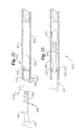
- FIG. 31 is a partial cross sectional view of a portion of a guidewire extension system having a first wire and a second wire in accordance with yet another exemplary embodiment of the invention.
- FIG. 32 is a partial cross sectional view of the guidewire system of FIG. 31 , wherein the first wire and the second wire are coupled together;
- FIG. 33 is a partial cross sectional view of a portion of a guidewire system having a first wire coupled to a second wire in accordance with yet another embodiment of the invention.
- FIG. 34 is an additional view of the guidewire system of FIG. 33 , in which the first wire and the second wire are separated;
- FIG. 35 is a partial cross sectional view of an exemplary embodiment of another invention disclosed herein relating to structure and methods of attaching a coil onto a tube or guidewire, showing an assembly including two different coils;
- FIG. 36 is a partial cross sectional view of an assembly in accordance with the embodiment of FIG. 35 , showing the coils disposed about a cylindrical member;
- FIG. 37 is an additional view of the assembly of FIG. 30 , showing the second coil tightened around the cylindrical member.
- FIG. 1 is a plan view of a guidewire extension system 100 in accordance with an exemplary embodiment of the invention.
- Guidewire system 100 includes a first wire 102 and a second wire 104 .
- First wire 102 comprises a body member 106 having a first end 120 and a second end 119 .
- First wire 102 also includes a distal tip 128 fixed to body member 106 proximate second end 119 .
- a distal sheath 130 is disposed about body member 106 proximate second end 119 .
- the distal sheath 130 is generally fixed in position relative to the body member.
- one end portion 114 of distal sheath 130 is fixed to distal tip 128 and another end portion 116 of distal sheath 130 is fixed to body member 106 of first wire 102 .
- distal sheath 130 has a high level of longitudinal pushability and a high level of lateral flexibility.
- Distal sheath 130 preferably comprises a coil 110 having a plurality of turns 112 .
- Body member 106 of first wire 102 preferably has a generally cylindrical shape.
- Second wire 104 includes a body member 108 having a first end 125 and a second end 126 . Second end 126 of second wire 104 is adapted and configured to be coupled to first end 120 of first wire 102 .
- FIG. 2 is a plan view illustrating first end portion 122 of first wire 102 and a second end portion 121 of second wire 104 in a non-coupled position.
- second wire 104 includes a plurality of struts 134 that extend beyond second end 126 of body member 108 of second wire 104 .
- Each strut 134 includes a proximal portion 136 which is fixed to body member 108 proximate second end 126 and a generally enlarged portion 140 .
- First wire 102 includes a plurality of struts 144 which extend beyond first end 120 of body member 106 of first wire 102 .
- Each strut 144 includes a proximal portion 137 which is fixed to body member 106 proximate first end 120 and a generally enlarged portion 141 .
- Proximal portions 137 define a plurality of apertures 150 .
- apertures 150 are sized to receive generally enlarged portions 140 of struts 134 .
- FIG. 3 is a plan view of the embodiment of FIG. 2 showing first end portion 122 of first wire 102 and second end portion 121 of second wire 104 and wherein struts 134 of second wire 104 have been deflected inward.
- struts 134 are deflected inward and second wire 104 is advanced toward first wire 102 until generally enlarged portions 140 of struts 134 are proximate apertures 150 defined by struts 144 .
- Struts 134 of second wire 104 are then released so that they are free to return to an undeflected state.
- first wire 102 and second wire 104 may become fixed to each other by an intermeshing of struts 144 of first wire 102 and struts 134 of second wire 104 .
- FIG. 4 is a plan view of first end portion 122 of first wire 102 and second end 121 of second wire 104 of FIGS. 2 and 3 .
- First wire 102 and second wire 104 are fixed to each other by an intermeshing of struts 144 of first wire 102 and struts 134 of second wire 104 .
- Generally enlarged portions 140 of struts 134 are disposed within apertures 150 defined by struts 144 .
- FIG. 5 is a partial perspective view of another exemplary embodiment of a guidewire extension system 200 .
- a first end portion 222 of a first wire 202 includes a body member 206 and a second end portion 221 of a second wire 204 includes a body member 208 .
- the first end portion 222 includes a generally hollow tubular portion 230 defining a cavity 232 therein.
- the tubular portion 230 has a tapered end 234 defining an opening 236 in fluid communication with the cavity 232 .
- the tubular portion 230 also defines an opening 237 in fluid communication with the cavity 232 .
- the opening 237 includes a wide portion 238 and a narrow portion 240 and is generally T-shaped.
- the narrow portion 240 is preferably in fluid communication with opening 236 .
- the second end portion 221 includes a recessed portion 242 and a wide portion 244 disposed on the end of the recessed portion 242 .
- the recessed portion 242 is generally annular in shape.
- the recessed portion 242 and the wide portion 244 together form structure 246 that is adapted and configured to mate with the tubular portion 230 to couple the first end portion 222 to the second end portion 221 .
- the structure can be inserted into the cavity 232 through the opening 237 .
- the wide portion 244 fits in to the wide portion 238 , and the recessed portion 242 fits into the narrow portion 240 .
- the wide portion 244 is pulled toward the tapered end 234 .
- the first and second wires are thereby selectively coupled together.
- FIG. 7 is an enlarged partial plan view of another embodiment.
- This embodiment includes a first end portion 322 of a first wire 302 including a body member 306 , and a second end portion 321 of a second wire 304 including a body member 308 .
- the second wire 304 includes a plurality of struts 334 which extend beyond a second end 326 of body member 308 of second wire 304 .
- Each strut 334 includes a proximal portion 336 which is fixed to body member 308 proximate second end 326 and a generally enlarged portion 340 .
- First wire 302 includes an outer surface 352 defining a plurality of apertures 350 .
- Outer surface 352 preferably has a generally cylindrical shape, although other shapes are contemplated.
- each aperture 350 is in fluid communication with a cavity 354 defined by body member 306 of first wire 302 but this is not necessary.
- Outer surface 252 of body member 306 of first wire 302 also defines a plurality of channels 356 .
- Each channel 356 is preferably in fluid communication with a cavity 354 .
- Each aperture 350 and its associated channel 356 form a generally keyhole shaped recess.
- body member 306 includes a tapered portion 358 proximate first end portion 322 .
- Tapered portion 358 preferably has an outer diameter that is less than an outer diameter of struts 334 . In some embodiments, at least a portion of the tapered portion 358 preferably has an outer diameter that is less than an inside diameter of a portion of struts 334 .
- FIG. 8 is a plan view of the embodiment of FIG. 9 , wherein the first end portion 322 of first wire 302 and second end portion 321 of second wire 304 have been urged toward one another and are partially coupled. Struts 334 of second wire 304 deflect outwardly as they ride upon an outer surface of tapered portion 358 .
- FIG. 9 is an additional plan view of FIGS. 7 and 8 wherein the first end portion 322 of first wire 302 and second end portion 321 of second wire 304 have been further urged toward one another and are coupled together.
- the generally enlarged portion 340 of each strut 334 of second wire 304 is disposed within a cavity 354 defined by body member 306 of first wire 302 .
- FIG. 10 is a perspective view of yet another exemplary embodiment of a guidewire system 400 .
- First end portion 422 of a first wire 402 and a second end portion 421 of a first wire 404 are shown.
- a body member 406 of first wire 402 defines a recess 460 , a tapered end portion 458 and a plurality of channels 456 .
- One channel 456 is visible in FIG. 10
- another channel (not visible in FIG. 10 ) is disposed generally opposite of the visible channel 456 .
- the recess 460 has a generally annular shape.
- the wire 404 includes struts 434 which extend beyond an end 426 of a body member 408 of wire 404 .
- Each strut 434 includes a proximal portion 436 which is fixed to body member 408 proximate end 426 and a generally enlarged portion 440 .
- Proximal portion 436 of struts 434 define a plurality of apertures 450 .
- FIG. 11 is a plan view of a portion of the guidewire system 400 shown in FIG. 10 . It can be appreciated that body member 406 of first wire 402 includes a tapered portion 458 proximate first end portion 422 .
- FIG. 12 is a plan view of first end portion 422 of first wire 402 and a second end portion 421 of second wire 404 of FIG. 11 wherein the wires are coupled together.
- First end portion 422 of first wire 402 and second end portion 421 of wire 404 have been urged toward one another.
- a generally enlarged portion 440 of each strut 434 of wire 404 is disposed within the annular recess 460 defined by a body member 406 of first wire 402 .
- each proximal portion 436 of each strut 434 is disposed within one of the channels 456 .
- FIG. 13 is a partial cross sectional view of a portion of a guidewire system 500 in accordance with yet another embodiment of the invention.
- Guidewire system 500 includes a first wire 502 including a first body member 504 having a first end portion 506 and a second wire 508 including a second body member 510 having a second end portion 512 .
- a first tubular member 514 is fixed to first body member 504 of first wire 502 proximate first end portion 506 thereof.
- First tubular member 514 includes a wall 516 defining a lumen 518 and a crimped portion 520 in which an inner diameter of wall 516 is generally reduced.
- a second tubular member 522 is fixed to second body member 510 of second wire 508 proximate second end portion 512 thereof.
- Second tubular member 522 defines a plurality of slots 524 . Slots 524 define a plurality of fingers 526 of second tubular member 522 . It can be appreciated that fingers 526 of second tubular member 522 are
- FIG. 14 is an additional view of guidewire system 500 of FIG. 13 , wherein the second tubular member 522 has been inserted into first tubular member 514 .
- fingers 526 of second tubular member 522 are adapted to seat against crimped portion 520 of first tubular member 514 to limit axial movement of second wire 508 relative to first wire 502 .
- Embodiments of first tubular member 514 are possible in which a crimped portion 520 comprises a plurality of depressions.
- Embodiments of second tubular member 522 are possible in which slots 524 and fingers 526 have a generally helical shape.
- FIG. 15 is a partial cross sectional view of a portion of a guidewire system 501 in accordance with yet another embodiment of the invention.
- Guidewire system 501 includes a first wire 503 including a first body member 505 having a first end portion 507 and a second wire 508 .
- the second wire 508 is substantially the same as second wire 508 shown in FIGS. 13 and 14 , with like reference numerals being used to identify like structures.
- the first wire 503 includes a first tubular member 515 and a second tubular member 517 coupled to the body member 505 proximate the end portion 507 of first wire 503 .
- the second tubular member 517 includes a narrow portion 519 that is adapted to fit within a portion of first tubular member 515 and forms an annulus within first tubular member.
- Narrow portion 519 includes an end surface 521 .
- FIG. 16 is an additional view of the guidewire system 501 of FIG. 15 , wherein the tubular member 522 has been inserted into the tubular members 515 and 517 to couple the two wires 501 and 508 together. It can be appreciated that fingers 526 of the second wire 508 are adapted to seat against the end surface 521 of the first wire 508 to limit the axial movement of the wires 503 and 508 relative to one another.
- FIG. 17 is a partial cross sectional view of a portion of a guidewire system 530 in accordance with yet another embodiment of the invention.
- Guidewire system 530 includes a first wire 532 including a first body member 534 having a first end 536 .
- First body member 534 of first wire 532 includes a first surface 544 and a second surface 546 that define an annular cavity 548 .
- Guidewire system 530 also includes a second wire 538 including a second body member 540 having a second end 542 .
- Second body member 540 of second wire 538 includes a wall 550 defining a lumen 552 and a plurality of flaps 554 extending into lumen 552 .
- FIG. 18 is an additional view of the guidewire system 530 of FIG. 17 wherein the first end 536 of first wire 532 has been inserted into the lumen 552 of the second wire 538 .
- the flaps 554 of second wire 538 are seated against second surface 546 of first wire 532 . Flaps 554 and second surface 546 preferably limit axial movement of second wire 538 relative to first wire 532 .
- FIG. 19 is a partial cross sectional view of a portion of a guidewire system 560 in accordance with yet another embodiment of the invention.
- Guidewire system 560 includes a first wire 562 including a first body member 564 having a first end 566 .
- First body member 564 of first wire 562 includes a first surface 574 and a second surface 576 that define an annular cavity 578 .
- Guidewire system 560 also includes a second wire 568 including a second body member 570 having a second end 572 .
- Second body member 570 of second wire 568 includes a wall 580 defining a lumen 584 and a plurality of arms 582 extending into lumen 584 .
- FIG. 20 is an additional view of the guidewire system 560 of FIG. 19 wherein first end 566 of first wire 562 has been inserted into lumen 584 of second wire 568 .
- the arms 582 of second wire 568 are seated against second surface 576 of first wire 562 .
- Arms 582 and second surface 576 preferably limit axial movement of second wire 568 relative to first wire 562 .
- FIG. 21 is a partial cross sectional view of a portion of a guidewire system 600 in accordance with yet another embodiment of the invention.
- Guidewire system 600 comprises a first wire 602 including a first body member 604 comprising a wall 606 defining a lumen 608 , and an annulus 610 disposed within lumen 608 proximate a first end 612 of first body member 604 .
- Annulus 610 of first wire 602 defines an aperture 622 and a first surface 624 .
- Guidewire system 600 also includes a second wire 614 .
- Second wire 614 includes a second body member 616 having a second end 618 .
- a coil 620 is disposed about second body member 616 of second wire 614 proximate second end 618 of second wire 614 .
- the coil 620 is maintained about second body member 616 by widening portion 617 proximate second end 618 of second wire 614 . It will be understood, however, that the coil 620 can be maintained on the second body member in a broad variety of other ways.
- FIG. 22 is an additional view of the guidewire system 600 of FIG. 21 , wherein the second end 618 of second wire 614 has been inserted into aperture 622 of annulus 610 of first wire 602 . It can be appreciated that coil 620 of second wire 614 may seat against first surface 624 of annulus 610 to limit axial movement of second wire 614 relative to first wire 602 .
- FIG. 23 is a partial cross sectional view of a portion of a guidewire system 601 in accordance with yet another embodiment of the invention.
- Guidewire system 601 comprises a first wire 602 that is substantially the same as the first wire 602 shown in FIGS. 21 and 22 , and therefore includes a first body member 604 comprising a wall 606 defining a lumen 608 , and an annulus 610 disposed within lumen 608 proximate a first end 612 of first body member 604 .
- Annulus 610 of first wire 602 defines an aperture 622 and a first surface 624 .
- Guidewire system 601 also includes a second wire 615 .
- Second wire 615 includes a second body member 619 having a second end 621 .
- a coil 623 is disposed about second body member 619 of second wire 615 proximate second end 621 of second wire 615 .
- the coil 623 is maintained about second body member 619 of second wire 615 by attachment of at least a portion of the coil 623 to the body member.
- FIG. 24 is an additional view of the guidewire system 601 of FIG. 23 .
- second end 621 of second wire 615 has been inserted into aperture 622 of annulus 610 of first wire 602 .
- coil 623 of second wire 615 can seat against first surface 624 of annulus 610 to limit axial movement of second wire 615 relative to first wire 602 .
- FIG. 25 is a partial cross sectional view of a portion of a guidewire system 631 in accordance with yet another embodiment of the invention.
- Guidewire system 631 comprises a first wire 503 that is substantially the same as the first wire 503 shown in FIGS. 15 and 16 , and a second wire 614 that is substantially the same as the second wire 614 shown in FIGS. 21 and 22 , with like reference numerals being used to identify like structure.
- FIG. 26 is an additional view of the guidewire system 631 of FIG. 25 , wherein the second end 618 of second wire 614 has been inserted into tubular members 515 and 517 to couple the wires 503 and 614 together. It can be appreciated that the coil 620 is adapted to seat against the end surface 521 of the first wire 503 to limit the axial movement of second wire 614 relative to first wire 503 .
- FIG. 27 is a partial cross sectional view of a portion of a guidewire system 651 in accordance with yet another embodiment of the invention.
- Guidewire system 651 comprises a first wire 503 that is substantially the same as the first wire 503 shown in FIGS. 15 and 16 , and a second wire 615 that is substantially the same as the second wire 615 shown in FIGS. 23 and 24 , with like reference numerals being used to identify like structure.
- FIG. 28 is an additional view of the guidewire system 651 of FIG. 27 , wherein the second end 621 of second wire 615 has been inserted into tubular members 515 and 517 to couple the wires together. It can be appreciated that the coil 623 is adapted to seat against the end surface 521 of the first wire 503 to limit the axial movement of second wire 615 relative to first wire 503 .
- FIG. 29 is a partial cross sectional view of a portion of a guidewire system 630 in accordance with yet another embodiment of the invention.
- Guidewire system 630 comprises a first wire 632 including a first body member 634 comprising a wall 636 defining a lumen 638 , and a female thread 640 disposed within lumen 638 proximate a first end 646 of first body member 634 .
- Female thread 640 of first wire 632 defines an aperture 642 and a first surface 644 .
- Guidewire system 630 also includes a second wire 648 .
- Second wire 648 includes a second body member 650 having a second end 652 .
- a coil 654 is disposed about second body member 650 of second wire 648 proximate second end 652 .
- at least a portion of the coil 654 is rigidly attached to the body member 650 .
- FIG. 30 is an additional view of the guidewire system 630 of FIG. 29 , wherein the coil 654 of second wire 648 has been threaded through female thread 640 of first wire 632 . It can be appreciated that coil 654 of second wire 648 can set against first surface 644 of female thread 640 to limit axial movement of second wire 648 relative to first wire 632 .
- FIG. 31 is a partial cross sectional view of a portion of a guidewire system 660 in accordance with yet another embodiment of the invention.
- Guidewire system 660 comprises a first wire 662 and a second wire 674 .
- First wire 662 includes a first body member 664 comprising a wall 668 defining a lumen 672 , and a female thread 670 disposed within lumen 672 proximate a first end 686 of first body member 664 .
- Second wire 674 includes a second body member 676 having a second end 678 .
- a male thread 680 is disposed about second body member 676 of second wire 674 proximate second end 678 of second wire 674 .
- Male thread 680 includes a first portion 682 which is adapted to threadingly engage female thread 670 .
- Male thread 680 also includes a second portion 684 which is different from first portion 682 of male thread 680 (e.g., different pitch or different thread size).
- second portion 684 of male thread 680 is adapted to deform when male thread 680 is threaded into female thread 670 .
- FIG. 32 is an additional view of guidewire system 660 of FIG. 21 , wherein the male thread 680 has been threaded into female thread 670 . Also it can be appreciated that second portion 684 of male thread 680 has been deformed. The deformation of second portion 684 of male thread 680 preferably acts to reduce or prevent rotation of female thread 670 relative to male thread 680 .
- FIG. 33 is a partial cross sectional view of a portion of a guidewire system 730 in accordance with yet another embodiment of the invention.
- Guidewire system 730 includes a first wire 732 including a first body member 734 having a first end 736 .
- First body member 734 of first wire 732 includes a zig-zag shaped tip portion 744 .
- First wire 732 also includes a first tubular member 746 which is disposed about zig-zag shaped tip portion 744 and fixed to first body member 734 .
- zigzag shaped tip portion 744 is a bias-able, yet resilient material.
- Guidewire system 730 also includes a second wire 738 including a second body member 740 having a second end 742 and a second tubular member 754 fixed to second body member 740 proximate second end 742 .
- Second tubular member 754 of second wire 738 includes a wall 750 defining a lumen 752 .
- the zigzag shaped tip portion 744 of first wire 732 is disposed within lumen 752 of second tubular member 754 .
- the zig-zag shaped tip portion 744 may be inserted into lumen 752 of second tubular member 754 by straightening it under spring tension and advancing it.
- FIG. 34 is an additional view of the guidewire system 730 of FIG. 33 , wherein the first wire 732 and second wire 738 have been separated from one another.
- FIG. 34 it can be appreciated that once zig-zag shaped tip portion 744 is removed from lumen 752 of second tubular member 754 , it is free to return to an uncompressed position.
- guidewires as disclosed herein in accordance with the invention can be used in conjunction with an intravascular catheter that enables a physician to remotely perform a therapeutic medical procedure.
- catheters include percutaneous transluminal angioplasty (PTA), percutaneous transluminal coronary angioplasty (PTCA), the treatment of intracranial aneurysms in the brain and the like.
- Guidewires are often utilized to assist in advancing the intravascular catheter through the vasculature of a patient.
- a guidewire may be inserted into the vascular system of the patient at an easily accessible location and urged forward through the vasculature until the tip of the guidewire is proximate the target site.
- a proximal end of the guidewire may then be inserted into a guidewire lumen of a catheter.
- the tip of the catheter may be advanced along the length of the guidewire until it reaches the target site.
- the first catheter be removed in a manner which enables the guidewire to remain in place in the blood vessel so that the second catheter can be inserted into the blood vessel over the guidewire.
- the guidewire In order to maintain the position of the guidewire while withdrawing the first catheter, the guidewire typically must be gripped at its proximal end to prevent it from being pulled out of the blood vessel together with the catheter.
- the extension system of at least some embodiments of the invention allow an extension wire to be attached to a proximal end of the guidewire which is already in place in the body. This effectively extends the overall length of the guidewire to that needed for catheter exchange.
- the connection between the guidewire and the extension wire preferably presents low resistance to catheters that are passed over the connection.
Abstract
Description
Claims (6)
Priority Applications (1)
| Application Number | Priority Date | Filing Date | Title |
|---|---|---|---|
| US09/925,881 US6911016B2 (en) | 2001-08-06 | 2001-08-06 | Guidewire extension system |
Applications Claiming Priority (1)
| Application Number | Priority Date | Filing Date | Title |
|---|---|---|---|
| US09/925,881 US6911016B2 (en) | 2001-08-06 | 2001-08-06 | Guidewire extension system |
Publications (2)
| Publication Number | Publication Date |
|---|---|
| US20030028127A1 US20030028127A1 (en) | 2003-02-06 |
| US6911016B2 true US6911016B2 (en) | 2005-06-28 |
Family
ID=25452385
Family Applications (1)
| Application Number | Title | Priority Date | Filing Date |
|---|---|---|---|
| US09/925,881 Expired - Fee Related US6911016B2 (en) | 2001-08-06 | 2001-08-06 | Guidewire extension system |
Country Status (1)
| Country | Link |
|---|---|
| US (1) | US6911016B2 (en) |
Cited By (51)
| Publication number | Priority date | Publication date | Assignee | Title |
|---|---|---|---|---|
| US20060106407A1 (en) * | 2004-11-17 | 2006-05-18 | Mcguckin James F Jr | Rotational thrombectomy wire |
| US20070088367A1 (en) * | 2004-10-22 | 2007-04-19 | Alexander Von Weymarn-Scharli | Device, especially tube or catheter, for at least partially introducing into a body passage |
| US20070123928A1 (en) * | 2005-11-30 | 2007-05-31 | Farnan Robert C | Embolic device delivery system with torque fracture characteristic |
| US20080015471A1 (en) * | 2003-12-05 | 2008-01-17 | Boston Scientific Scimed, Inc. | Elongated medical device for intracorporal use |
| US20090036877A1 (en) * | 2007-08-01 | 2009-02-05 | Boston Scientific Scimed, Inc. | Spring detach joint for delivering a detachable implantable device |
| US20090069709A1 (en) * | 2007-09-06 | 2009-03-12 | Baxano, Inc. | Method, system, and apparatus for neural localization |
| US20090143768A1 (en) * | 2007-04-23 | 2009-06-04 | Interventional & Surgical Innovations, Llc | Guidewire with adjustable stiffness |
| US20090204119A1 (en) * | 2004-10-15 | 2009-08-13 | Bleich Jeffery L | Devices and methods for tissue modification |
| US20100222661A1 (en) * | 2007-10-26 | 2010-09-02 | St. Jude Medical Systems Ab | Joining of sensor guide wire |
| US20100274250A1 (en) * | 2008-07-01 | 2010-10-28 | Wallace Michael P | Tissue modification devices and methods |
| US20100292614A1 (en) * | 2007-10-02 | 2010-11-18 | Cook Incorporated | Medical systems, devices and methods for coupling wire guides |
| US7857813B2 (en) * | 2006-08-29 | 2010-12-28 | Baxano, Inc. | Tissue access guidewire system and method |
| US7918849B2 (en) | 2004-10-15 | 2011-04-05 | Baxano, Inc. | Devices and methods for tissue access |
| US7938830B2 (en) | 2004-10-15 | 2011-05-10 | Baxano, Inc. | Powered tissue modification devices and methods |
| US7963915B2 (en) | 2004-10-15 | 2011-06-21 | Baxano, Inc. | Devices and methods for tissue access |
| US20110224653A1 (en) * | 2008-11-14 | 2011-09-15 | Coloplast A/S | Coupling arrangement for a telescopic device |
| US8048080B2 (en) | 2004-10-15 | 2011-11-01 | Baxano, Inc. | Flexible tissue rasp |
| US20110271904A1 (en) * | 2006-05-04 | 2011-11-10 | Jason Van Sciver | Rotatable support elements for stents |
| US8062325B2 (en) | 2006-07-31 | 2011-11-22 | Codman & Shurtleff, Inc. | Implantable medical device detachment system and methods of using the same |
| US8062298B2 (en) | 2005-10-15 | 2011-11-22 | Baxano, Inc. | Flexible tissue removal devices and methods |
| US8062300B2 (en) | 2006-05-04 | 2011-11-22 | Baxano, Inc. | Tissue removal with at least partially flexible devices |
| US8092456B2 (en) | 2005-10-15 | 2012-01-10 | Baxano, Inc. | Multiple pathways for spinal nerve root decompression from a single access point |
| US8192436B2 (en) | 2007-12-07 | 2012-06-05 | Baxano, Inc. | Tissue modification devices |
| US8257356B2 (en) | 2004-10-15 | 2012-09-04 | Baxano, Inc. | Guidewire exchange systems to treat spinal stenosis |
| US8366720B2 (en) | 2006-07-31 | 2013-02-05 | Codman & Shurtleff, Inc. | Interventional medical device system having an elongation retarding portion and method of using the same |
| US8366712B2 (en) | 2005-10-15 | 2013-02-05 | Baxano, Inc. | Multiple pathways for spinal nerve root decompression from a single access point |
| US8394102B2 (en) | 2009-06-25 | 2013-03-12 | Baxano, Inc. | Surgical tools for treatment of spinal stenosis |
| US8398641B2 (en) | 2008-07-01 | 2013-03-19 | Baxano, Inc. | Tissue modification devices and methods |
| US8419653B2 (en) | 2005-05-16 | 2013-04-16 | Baxano, Inc. | Spinal access and neural localization |
| US8430881B2 (en) | 2004-10-15 | 2013-04-30 | Baxano, Inc. | Mechanical tissue modification devices and methods |
| US8568416B2 (en) | 2004-10-15 | 2013-10-29 | Baxano Surgical, Inc. | Access and tissue modification systems and methods |
| US8613745B2 (en) | 2004-10-15 | 2013-12-24 | Baxano Surgical, Inc. | Methods, systems and devices for carpal tunnel release |
| US8663259B2 (en) | 2010-05-13 | 2014-03-04 | Rex Medical L.P. | Rotational thrombectomy wire |
| US8764779B2 (en) | 2010-05-13 | 2014-07-01 | Rex Medical, L.P. | Rotational thrombectomy wire |
| US8801626B2 (en) | 2004-10-15 | 2014-08-12 | Baxano Surgical, Inc. | Flexible neural localization devices and methods |
| US8845639B2 (en) | 2008-07-14 | 2014-09-30 | Baxano Surgical, Inc. | Tissue modification devices |
| US9023070B2 (en) | 2010-05-13 | 2015-05-05 | Rex Medical, L.P. | Rotational thrombectomy wire coupler |
| US9101386B2 (en) | 2004-10-15 | 2015-08-11 | Amendia, Inc. | Devices and methods for treating tissue |
| US9247952B2 (en) | 2004-10-15 | 2016-02-02 | Amendia, Inc. | Devices and methods for tissue access |
| US9307996B2 (en) | 2005-12-13 | 2016-04-12 | DePuy Synthes Products, Inc. | Detachment actuator for use with medical device deployment systems |
| US9314253B2 (en) | 2008-07-01 | 2016-04-19 | Amendia, Inc. | Tissue modification devices and methods |
| US9387309B2 (en) | 2007-04-23 | 2016-07-12 | Cardioguidance Biomedical, Llc | Guidewire with adjustable stiffness |
| US9456829B2 (en) | 2004-10-15 | 2016-10-04 | Amendia, Inc. | Powered tissue modification devices and methods |
| US20170007402A1 (en) * | 2014-02-18 | 2017-01-12 | Medtentia International Ltd Oy | Medical Device for a Cardiac Valve Implant |
| US9585784B2 (en) | 2011-08-29 | 2017-03-07 | Coloplast A/S | Catheter activation by handle removal |
| US20170087335A1 (en) * | 2013-03-06 | 2017-03-30 | Cook Medical Technologies Llc | System for a wire-lumen free balloon catheter |
| US9795406B2 (en) | 2010-05-13 | 2017-10-24 | Rex Medical, L.P. | Rotational thrombectomy wire |
| US9968762B2 (en) | 2012-08-08 | 2018-05-15 | Cook Medical Technologies Llc | Wire guide with multiple tips |
| US10543344B2 (en) | 2014-08-15 | 2020-01-28 | Jaafer Golzar | Double-ended wire guide and method of use thereof |
| US11202888B2 (en) | 2017-12-03 | 2021-12-21 | Cook Medical Technologies Llc | MRI compatible interventional wireguide |
| US11819430B2 (en) | 2017-11-03 | 2023-11-21 | Ceroflo Limited | Expandable stent and a method for promoting a natural intracranial angiogenesis process, and use of the expandable stent in the method for promoting a natural intracranial angiogenesis process |
Families Citing this family (37)
| Publication number | Priority date | Publication date | Assignee | Title |
|---|---|---|---|---|
| US20040225250A1 (en) | 2003-05-05 | 2004-11-11 | Michael Yablonski | Internal shunt and method for treating glaucoma |
| US7758520B2 (en) * | 2003-05-27 | 2010-07-20 | Boston Scientific Scimed, Inc. | Medical device having segmented construction |
| US7291125B2 (en) | 2003-11-14 | 2007-11-06 | Transcend Medical, Inc. | Ocular pressure regulation |
| JP4722122B2 (en) | 2004-03-17 | 2011-07-13 | クック インコーポレイテッド | Second wire device and mounting procedure |
| US8075497B2 (en) * | 2005-08-25 | 2011-12-13 | Cook Medical Technologies Llc | Wire guide having distal coupling tip |
| US9005138B2 (en) | 2005-08-25 | 2015-04-14 | Cook Medical Technologies Llc | Wire guide having distal coupling tip |
| US7758565B2 (en) * | 2005-10-18 | 2010-07-20 | Cook Incorporated | Identifiable wire guide |
| US8137291B2 (en) * | 2005-10-27 | 2012-03-20 | Cook Medical Technologies Llc | Wire guide having distal coupling tip |
| US7731693B2 (en) * | 2005-10-27 | 2010-06-08 | Cook Incorporated | Coupling wire guide |
| US7811238B2 (en) * | 2006-01-13 | 2010-10-12 | Cook Incorporated | Wire guide having distal coupling tip |
| EP3005996B1 (en) | 2006-01-17 | 2019-12-04 | Novartis Ag | Glaucoma treatment device |
| US7785275B2 (en) * | 2006-01-31 | 2010-08-31 | Cook Incorporated | Wire guide having distal coupling tip |
| US7798980B2 (en) * | 2006-01-31 | 2010-09-21 | Cook Incorporated | Wire guide having distal coupling tip for attachment to a previously introduced wire guide |
| US20070191790A1 (en) * | 2006-02-16 | 2007-08-16 | Cook Incorporated | Wire guide having distal coupling tip |
| US8133190B2 (en) * | 2006-06-22 | 2012-03-13 | Cook Medical Technologies Llc | Weldable wire guide with distal coupling tip |
| ATE543449T1 (en) * | 2006-12-07 | 2012-02-15 | Baxano Inc | DEVICES FOR TISSUE REMOVAL |
| WO2008105756A1 (en) * | 2007-02-26 | 2008-09-04 | Cook Incorporated | Wire guide having distal coupling tip |
| US20080306453A1 (en) * | 2007-06-06 | 2008-12-11 | Cook Incorporated | Coupling wire guide and method for making same |
| US8377122B2 (en) | 2009-01-28 | 2013-02-19 | Transcend Medical, Inc. | Ocular implant with stiffness qualities, methods of implantation and system |
| US9539670B2 (en) | 2010-05-25 | 2017-01-10 | Creganna-Tactx Medical | Joint for tubular materials |
| EP2686056A1 (en) * | 2011-03-15 | 2014-01-22 | Boston Scientific Scimed, Inc. | Multiple guidewire system |
| US8602641B2 (en) * | 2011-10-26 | 2013-12-10 | Temptronic Corporation | Environmental test system and method with in-situ temperature sensing of device under test (DUT) |
| US10085633B2 (en) | 2012-04-19 | 2018-10-02 | Novartis Ag | Direct visualization system for glaucoma treatment |
| US9241832B2 (en) | 2012-04-24 | 2016-01-26 | Transcend Medical, Inc. | Delivery system for ocular implant |
| US9757536B2 (en) * | 2012-07-17 | 2017-09-12 | Novartis Ag | Soft tip cannula |
| WO2014036507A1 (en) * | 2012-08-31 | 2014-03-06 | Volcano Corporation | Mounting structures for components of intravascular devices |
| EP3228286A1 (en) | 2012-09-17 | 2017-10-11 | Novartis AG | Expanding ocular impant devices |
| WO2014078288A1 (en) | 2012-11-14 | 2014-05-22 | Transcend Medical, Inc. | Flow promoting ocular implant |
| US20140316449A1 (en) * | 2013-03-14 | 2014-10-23 | Cardiovascular Systems, Inc. | Devices, systems and methods for a quick load guide wire tool |
| US9901716B2 (en) * | 2013-09-10 | 2018-02-27 | Cook Medical Technologies Llc | Tipless balloon catheter with stiffening member through balloon |
| US10251630B2 (en) | 2015-08-28 | 2019-04-09 | SiteSelect Inc. | Tissue excision device with anchor stability rod and anchor stability rod |
| EP3340889A4 (en) * | 2015-08-28 | 2019-05-08 | Siteselect Inc. | Tissue excision device with anchor stability rod and anchor stability rod |
| CN109789292B (en) * | 2016-10-05 | 2022-11-01 | 祥丰医疗私人有限公司 | Modular vascular catheter |
| US11052229B2 (en) * | 2017-08-15 | 2021-07-06 | Corelink, Llc | Devices and methods for guidewire extension in spinal surgery |
| US11835158B2 (en) * | 2017-12-15 | 2023-12-05 | Viant As&O Holdings, Llc | Mechanical joining of Nitinol tubes |
| US11885442B2 (en) * | 2017-12-15 | 2024-01-30 | Viant As&O Holdings, Llc | Mechanical joining of nitinol tubes |
| WO2023099961A1 (en) * | 2021-12-01 | 2023-06-08 | Petrus Antonius Besselink | Extension system for coupling tubular devices |
Citations (84)
| Publication number | Priority date | Publication date | Assignee | Title |
|---|---|---|---|---|
| US3631848A (en) | 1968-09-04 | 1972-01-04 | Us Catheter & Instr Corp | Extensible catheter |
| EP0160870A2 (en) | 1984-05-04 | 1985-11-13 | Boston Scientific Corporation | Medical retriever device |
| US4700705A (en) * | 1985-08-12 | 1987-10-20 | Intravascular Surgical Instruments, Inc. | Catheter based surgical methods and apparatus therefor |
| EP0313807A1 (en) | 1987-09-21 | 1989-05-03 | Advanced Cardiovascular Systems, Inc. | Extendable guidewire for vascular procedures |
| US4827941A (en) | 1987-12-23 | 1989-05-09 | Advanced Cardiovascular Systems, Inc. | Extendable guidewire for cardiovascular procedures |
| US4875489A (en) | 1987-08-14 | 1989-10-24 | Advanced Cardiovascular Systems, Inc. | Extendable guidewire |
| US4907332A (en) | 1988-01-11 | 1990-03-13 | Advanced Cardiovascular Systems, Inc. | Device for connecting extendable guidewire sections for cardiovascular procedures |
| US4917103A (en) | 1985-09-18 | 1990-04-17 | C. R. Bard, Inc. | Guide wire extension |
| US4922923A (en) | 1985-09-18 | 1990-05-08 | C. R. Bard, Inc. | Method for effecting a catheter exchange |
| EP0367472A2 (en) | 1988-11-02 | 1990-05-09 | Cardiometrics, Inc. | Guide wire assembly |
| EP0383159A1 (en) | 1989-02-14 | 1990-08-22 | Advanced Cardiovascular Systems, Inc. | Extendable guidewire for vascular procedures |
| US4961433A (en) | 1988-11-02 | 1990-10-09 | Cardiometrics, Inc. | Guide wire assembly with electrical functions and male and female connectors for use therewith |
| US5031636A (en) | 1985-09-18 | 1991-07-16 | C. R. Bard, Inc. | Guide wire extension |
| US5109867A (en) | 1991-04-19 | 1992-05-05 | Target Therapeutics | Extendable guidewire assembly |
| US5113872A (en) | 1990-04-18 | 1992-05-19 | Cordis Corporation | Guidewire extension system with connectors |
| US5117838A (en) | 1990-04-18 | 1992-06-02 | Cordis Corporation | Rotating guidewire extension system |
| US5133364A (en) | 1988-06-13 | 1992-07-28 | C. R. Bard, Inc. | Guidewire extension with self-latching detachable connector |
| US5139032A (en) | 1990-04-18 | 1992-08-18 | Cordis Corporation | Fixed balloon on a guidewire extension wire system and kit |
| US5188621A (en) | 1991-08-26 | 1993-02-23 | Target Therapeutics Inc. | Extendable guidewire assembly |
| WO1993003664A2 (en) | 1991-08-21 | 1993-03-04 | Baxter International Inc. | Guidewire extension system |
| US5191888A (en) | 1990-04-18 | 1993-03-09 | Cordis Corporation | Assembly of an extension guidewire and an alignment tool for same |
| US5195540A (en) | 1991-08-12 | 1993-03-23 | Samuel Shiber | Lesion marking process |
| US5195535A (en) | 1990-11-09 | 1993-03-23 | C. R. Bard, Inc. | Detachable guidewire extension |
| WO1993013827A1 (en) | 1992-01-09 | 1993-07-22 | Advanced Cardiovascular Systems, Inc. | Guidewire replacement device |
| WO1993014805A1 (en) | 1992-01-28 | 1993-08-05 | Baxter International, Inc. | Guidewire extension system |
| US5234002A (en) * | 1991-10-11 | 1993-08-10 | Advanced Cardiovascular Systems, Inc. | Catheter exchange system |
| US5247942A (en) | 1992-04-06 | 1993-09-28 | Scimed Life Systems, Inc. | Guide wire with swivel |
| US5267573A (en) | 1992-11-13 | 1993-12-07 | Oakley, Inc. | Guidewire extender |
| USRE34466E (en) | 1987-12-23 | 1993-12-07 | Advanced Cardiovascular Systems, Inc. | Extendable guidewire for cardiovascular procedures |
| US5295492A (en) | 1992-10-09 | 1994-03-22 | C. R. Bard, Inc. | Device for connecting a guidewire to an extension guidewire |
| EP0591945A1 (en) | 1992-10-09 | 1994-04-13 | C.R. Bard, Inc. | Guidewire extension with selflatching detachable connector |
| US5338301A (en) | 1993-08-26 | 1994-08-16 | Cordis Corporation | Extendable balloon-on-a-wire catheter, system and treatment procedure |
| US5339833A (en) | 1991-08-21 | 1994-08-23 | C.R. Bard, Inc. | Swivel exchange guidewire |
| US5341817A (en) | 1992-12-14 | 1994-08-30 | Cordis Corporation | Elongated guidewire for use in dilation procedures |
| EP0397055B1 (en) | 1989-05-11 | 1994-10-05 | Advanced Cardiovascular Systems, Inc. | Dilatation catheter suitable for peripheral arteries |
| WO1994025097A1 (en) | 1993-04-26 | 1994-11-10 | Mallinckrodt Medical, Inc. | Method of joining portions of inflation catheter |
| US5364355A (en) | 1993-06-18 | 1994-11-15 | Advanced Cardiovascular Systems, Inc. | Holding system for coiled intravascular products |
| US5365942A (en) * | 1990-06-04 | 1994-11-22 | C. R. Bard, Inc. | Guidewire tip construction |
| WO1994026343A1 (en) | 1993-05-14 | 1994-11-24 | Schneider (Usa) Inc. | Exchangeable guidewire |
| WO1995008294A1 (en) | 1993-09-24 | 1995-03-30 | Cardiometrics, Inc. | Extension device, assembly thereof, heater for use therewith and method |
| US5404888A (en) | 1992-02-10 | 1995-04-11 | Datascope Investment Corp. | Guide wire extension |
| US5415178A (en) | 1991-08-26 | 1995-05-16 | Target Therapeutics | Extendable guidewire assembly |
| US5421348A (en) | 1993-11-29 | 1995-06-06 | Cordis Corporation | Rotating guidewire extension system with mechanically locking extension wire |
| US5441055A (en) | 1994-06-27 | 1995-08-15 | Cordis Corporation | Guidewire extension wire and connector assembly |
| US5454785A (en) | 1993-04-12 | 1995-10-03 | C. R. Bard, Inc. | Method of withdrawing and exchanging catheters |
| EP0689849A1 (en) | 1994-04-11 | 1996-01-03 | Schneider (Europe) Ag | A docking assembly for the extension of a guidewire |
| JPH0884776A (en) | 1994-09-16 | 1996-04-02 | Nippon Zeon Co Ltd | Method for jointing guide wire and guide wire used therefor, auxiliary tool for jointing and heat-welding apparatus used for the method |
| US5513650A (en) | 1995-02-28 | 1996-05-07 | Medtronic, Inc. | Guidewire extension connector - keyed joint |
| US5542938A (en) | 1992-07-28 | 1996-08-06 | Cordis Corporation | Magnetic guidewire coupling for catheter exchange |
| US5546958A (en) | 1994-03-31 | 1996-08-20 | Lake Region Manufacturing Company, Inc. | Guidewire extension system with tactile connection indication |
| EP0689850B1 (en) | 1994-05-11 | 1996-09-25 | Schneider (Europe) Ag | Docking assembly for the extension of a guidewire |
| WO1996029001A1 (en) | 1995-03-17 | 1996-09-26 | Intelliwire, Inc. | Flexible guide wire with extension capability and guide wire extension for use therewith |
| JPH0951954A (en) | 1995-08-15 | 1997-02-25 | Nippon Zeon Co Ltd | Wire guide fixture and catheter set having the fixture |
| US5693083A (en) * | 1983-12-09 | 1997-12-02 | Endovascular Technologies, Inc. | Thoracic graft and delivery catheter |
| US5701911A (en) | 1996-04-05 | 1997-12-30 | Medtronic, Inc. | Guide wire extension docking system |
| EP0815892A1 (en) | 1996-06-25 | 1998-01-07 | Schneider (Europe) Ag | Docking assembly for the extension of a guidewire |
| JPH1043310A (en) | 1996-08-02 | 1998-02-17 | Terumo Corp | Catheter apparatus |
| WO1998026833A1 (en) | 1996-12-16 | 1998-06-25 | University Of Southern California | Angioplasty catheter |
| US5788653A (en) | 1996-04-03 | 1998-08-04 | Cordis Corporation | Guidewire extension with sliding release mechanism |
| US5792075A (en) | 1995-04-11 | 1998-08-11 | Schneider (Europe) A.G. | Method and apparatus for extending the length of a guide wire |
| US5813996A (en) | 1995-12-21 | 1998-09-29 | Scimed Life Systems, Inc. | Guide wire extension system with magnetic coupling |
| US5813405A (en) | 1990-04-18 | 1998-09-29 | Cordis Corporation | Snap-in connection assembly for extension guidewire system |
| US5827241A (en) | 1995-06-07 | 1998-10-27 | C. R. Bard, Inc. | Rapid exchange guidewire mechanism |
| US5830157A (en) | 1997-05-09 | 1998-11-03 | Merit Medical Systems, Inc. | Guidewire connection guide and method of use |
| US5851192A (en) | 1997-06-24 | 1998-12-22 | Asahi Intecc Co., Ltd. | Connecting structure of the guide wire used for medical treatment |
| US5853375A (en) | 1995-11-29 | 1998-12-29 | Medtronic, Inc. | Guide wire extension peg and hole with 90 degree latch |
| US5897567A (en) * | 1993-04-29 | 1999-04-27 | Scimed Life Systems, Inc. | Expandable intravascular occlusion material removal devices and methods of use |
| JPH11128361A (en) | 1986-01-18 | 1999-05-18 | Terumo Corp | Connecting-type wire |
| JPH11128362A (en) | 1986-01-18 | 1999-05-18 | Terumo Corp | Connecting-type wire for catheter |
| US5980471A (en) | 1997-10-10 | 1999-11-09 | Advanced Cardiovascular System, Inc. | Guidewire with tubular connector |
| US5994667A (en) * | 1997-10-15 | 1999-11-30 | Scimed Life Systems, Inc. | Method and apparatus for laser cutting hollow workpieces |
| US6080117A (en) | 1997-10-16 | 2000-06-27 | Scimed Life Systems, Inc. | Guide wire extension system |
| US6090052A (en) | 1997-03-25 | 2000-07-18 | Radi Medical Systems Ab | Guide wire having a male connector |
| US6099534A (en) | 1997-10-01 | 2000-08-08 | Scimed Life Systems, Inc. | Releasable basket |
| WO2000045885A1 (en) | 1999-02-02 | 2000-08-10 | Boston Scientific Limited | Catheter with spiral cut transition member |
| US6152914A (en) | 1999-01-22 | 2000-11-28 | Medtronic, Inc. | Catheter having a multiple locking mechanism |
| US6196980B1 (en) | 1997-09-10 | 2001-03-06 | Radi Medical System Ab | Male connector with a continuous surface for a guide wire, and method therefor |
| US6217526B1 (en) | 1989-04-25 | 2001-04-17 | Medtronic Ave, Inc. | Detachable guidewire extension |
| US6240615B1 (en) * | 1998-05-05 | 2001-06-05 | Advanced Cardiovascular Systems, Inc. | Method and apparatus for uniformly crimping a stent onto a catheter |
| US6270476B1 (en) * | 1999-04-23 | 2001-08-07 | Cryocath Technologies, Inc. | Catheter |
| US6322586B1 (en) * | 2000-01-10 | 2001-11-27 | Scimed Life Systems, Inc. | Catheter tip designs and method of manufacture |
| US6436056B1 (en) * | 1996-02-28 | 2002-08-20 | Boston Scientific Corporation | Polymeric implements for torque transmission |
| US6440503B1 (en) * | 2000-02-25 | 2002-08-27 | Scimed Life Systems, Inc. | Laser deposition of elements onto medical devices |
| US6575920B2 (en) * | 2001-05-30 | 2003-06-10 | Scimed Life Systems, Inc. | Distal tip portion for a guide wire |
-
2001
- 2001-08-06 US US09/925,881 patent/US6911016B2/en not_active Expired - Fee Related
Patent Citations (107)
| Publication number | Priority date | Publication date | Assignee | Title |
|---|---|---|---|---|
| US3631848A (en) | 1968-09-04 | 1972-01-04 | Us Catheter & Instr Corp | Extensible catheter |
| US5693083A (en) * | 1983-12-09 | 1997-12-02 | Endovascular Technologies, Inc. | Thoracic graft and delivery catheter |
| EP0160870A2 (en) | 1984-05-04 | 1985-11-13 | Boston Scientific Corporation | Medical retriever device |
| US4700705A (en) * | 1985-08-12 | 1987-10-20 | Intravascular Surgical Instruments, Inc. | Catheter based surgical methods and apparatus therefor |
| US4922923A (en) | 1985-09-18 | 1990-05-08 | C. R. Bard, Inc. | Method for effecting a catheter exchange |
| US5031636A (en) | 1985-09-18 | 1991-07-16 | C. R. Bard, Inc. | Guide wire extension |
| US4917103A (en) | 1985-09-18 | 1990-04-17 | C. R. Bard, Inc. | Guide wire extension |
| JPH11128362A (en) | 1986-01-18 | 1999-05-18 | Terumo Corp | Connecting-type wire for catheter |
| JPH11128361A (en) | 1986-01-18 | 1999-05-18 | Terumo Corp | Connecting-type wire |
| US4875489A (en) | 1987-08-14 | 1989-10-24 | Advanced Cardiovascular Systems, Inc. | Extendable guidewire |
| EP0313807A1 (en) | 1987-09-21 | 1989-05-03 | Advanced Cardiovascular Systems, Inc. | Extendable guidewire for vascular procedures |
| US4846193A (en) | 1987-09-21 | 1989-07-11 | Advanced Cardiovascular Systems, Inc. | Extendable guide wire for vascular procedures |
| EP0566523A1 (en) | 1987-12-23 | 1993-10-20 | Advanced Cardiovascular Systems, Inc. | Extendable guidewire for cardiovascular procedures |
| USRE34466E (en) | 1987-12-23 | 1993-12-07 | Advanced Cardiovascular Systems, Inc. | Extendable guidewire for cardiovascular procedures |
| US4827941A (en) | 1987-12-23 | 1989-05-09 | Advanced Cardiovascular Systems, Inc. | Extendable guidewire for cardiovascular procedures |
| US4907332A (en) | 1988-01-11 | 1990-03-13 | Advanced Cardiovascular Systems, Inc. | Device for connecting extendable guidewire sections for cardiovascular procedures |
| US5133364A (en) | 1988-06-13 | 1992-07-28 | C. R. Bard, Inc. | Guidewire extension with self-latching detachable connector |
| EP0347035B1 (en) | 1988-06-13 | 1994-10-05 | C.R. Bard, Inc. | Guidewire extension with selflatching detachable connection |
| US4961433A (en) | 1988-11-02 | 1990-10-09 | Cardiometrics, Inc. | Guide wire assembly with electrical functions and male and female connectors for use therewith |
| EP0367472A2 (en) | 1988-11-02 | 1990-05-09 | Cardiometrics, Inc. | Guide wire assembly |
| US4958642A (en) | 1988-11-02 | 1990-09-25 | Cardiometrics, Inc. | Guide wire assembly with electrical functions and male and female connectors for use therewith |
| US4966163A (en) | 1989-02-14 | 1990-10-30 | Advanced Cardiovascular Systems, Inc. | Extendable guidewire for vascular procedures |
| EP0383159A1 (en) | 1989-02-14 | 1990-08-22 | Advanced Cardiovascular Systems, Inc. | Extendable guidewire for vascular procedures |
| US6217526B1 (en) | 1989-04-25 | 2001-04-17 | Medtronic Ave, Inc. | Detachable guidewire extension |
| EP0397055B1 (en) | 1989-05-11 | 1994-10-05 | Advanced Cardiovascular Systems, Inc. | Dilatation catheter suitable for peripheral arteries |
| US5139032A (en) | 1990-04-18 | 1992-08-18 | Cordis Corporation | Fixed balloon on a guidewire extension wire system and kit |
| US5191888A (en) | 1990-04-18 | 1993-03-09 | Cordis Corporation | Assembly of an extension guidewire and an alignment tool for same |
| US5813405A (en) | 1990-04-18 | 1998-09-29 | Cordis Corporation | Snap-in connection assembly for extension guidewire system |
| US5113872A (en) | 1990-04-18 | 1992-05-19 | Cordis Corporation | Guidewire extension system with connectors |
| US5117838A (en) | 1990-04-18 | 1992-06-02 | Cordis Corporation | Rotating guidewire extension system |
| US5365942A (en) * | 1990-06-04 | 1994-11-22 | C. R. Bard, Inc. | Guidewire tip construction |
| US5195535A (en) | 1990-11-09 | 1993-03-23 | C. R. Bard, Inc. | Detachable guidewire extension |
| US5109867A (en) | 1991-04-19 | 1992-05-05 | Target Therapeutics | Extendable guidewire assembly |
| WO1992018051A1 (en) | 1991-04-19 | 1992-10-29 | Target Therapeutics, Inc. | Extendable guidewire assembly |
| US5195540A (en) | 1991-08-12 | 1993-03-23 | Samuel Shiber | Lesion marking process |
| WO1993003664A2 (en) | 1991-08-21 | 1993-03-04 | Baxter International Inc. | Guidewire extension system |
| US5339833A (en) | 1991-08-21 | 1994-08-23 | C.R. Bard, Inc. | Swivel exchange guidewire |
| US5282478A (en) | 1991-08-21 | 1994-02-01 | Baxter International, Inc. | Guidewire extension system with coil connectors |
| US5188621A (en) | 1991-08-26 | 1993-02-23 | Target Therapeutics Inc. | Extendable guidewire assembly |
| WO1993003786A1 (en) | 1991-08-26 | 1993-03-04 | Target Therapeutics, Inc. | Extendable guidewire assembly |
| US5275173A (en) | 1991-08-26 | 1994-01-04 | Target Therapeutics, Inc. | Extendable guidewire assembly |
| US5415178A (en) | 1991-08-26 | 1995-05-16 | Target Therapeutics | Extendable guidewire assembly |
| US5234002A (en) * | 1991-10-11 | 1993-08-10 | Advanced Cardiovascular Systems, Inc. | Catheter exchange system |
| WO1993013827A1 (en) | 1992-01-09 | 1993-07-22 | Advanced Cardiovascular Systems, Inc. | Guidewire replacement device |
| WO1993014805A1 (en) | 1992-01-28 | 1993-08-05 | Baxter International, Inc. | Guidewire extension system |
| US5271415A (en) | 1992-01-28 | 1993-12-21 | Baxter International Inc. | Guidewire extension system |
| US5404888A (en) | 1992-02-10 | 1995-04-11 | Datascope Investment Corp. | Guide wire extension |
| US5247942A (en) | 1992-04-06 | 1993-09-28 | Scimed Life Systems, Inc. | Guide wire with swivel |
| US5542938A (en) | 1992-07-28 | 1996-08-06 | Cordis Corporation | Magnetic guidewire coupling for catheter exchange |
| US5365944A (en) | 1992-10-09 | 1994-11-22 | C. R. Bard, Inc. | Guidewire extension with self-latching detachable connector |
| US5361777A (en) | 1992-10-09 | 1994-11-08 | C.R. Bard, Inc. | Device for connecting a guidewire to an extension guidewire |
| EP0591945A1 (en) | 1992-10-09 | 1994-04-13 | C.R. Bard, Inc. | Guidewire extension with selflatching detachable connector |
| US5295492A (en) | 1992-10-09 | 1994-03-22 | C. R. Bard, Inc. | Device for connecting a guidewire to an extension guidewire |
| US5267573A (en) | 1992-11-13 | 1993-12-07 | Oakley, Inc. | Guidewire extender |
| WO1994011049A1 (en) | 1992-11-13 | 1994-05-26 | Pilot Cardiovascular Systems, Inc. | Guidewire extender |
| US5341817A (en) | 1992-12-14 | 1994-08-30 | Cordis Corporation | Elongated guidewire for use in dilation procedures |
| US5454785A (en) | 1993-04-12 | 1995-10-03 | C. R. Bard, Inc. | Method of withdrawing and exchanging catheters |
| WO1994025097A1 (en) | 1993-04-26 | 1994-11-10 | Mallinckrodt Medical, Inc. | Method of joining portions of inflation catheter |
| US5395336A (en) | 1993-04-26 | 1995-03-07 | Mallinckrodt Medical, Inc. | Method for joining portions of a inflation/expansion catheter and a catheter so formed |
| US5897567A (en) * | 1993-04-29 | 1999-04-27 | Scimed Life Systems, Inc. | Expandable intravascular occlusion material removal devices and methods of use |
| WO1994026343A1 (en) | 1993-05-14 | 1994-11-24 | Schneider (Usa) Inc. | Exchangeable guidewire |
| US5511559A (en) | 1993-05-14 | 1996-04-30 | Schneider (Usa) Inc. | Exchangeable guidewire |
| US5404886A (en) | 1993-05-14 | 1995-04-11 | Schneider (Usa) Inc. | Exchangeable guidewire |
| EP0697899B1 (en) | 1993-05-14 | 1997-12-17 | Schneider (Usa) Inc. | Exchangeable guidewire |
| US5364355A (en) | 1993-06-18 | 1994-11-15 | Advanced Cardiovascular Systems, Inc. | Holding system for coiled intravascular products |
| US5338301A (en) | 1993-08-26 | 1994-08-16 | Cordis Corporation | Extendable balloon-on-a-wire catheter, system and treatment procedure |
| WO1995008294A1 (en) | 1993-09-24 | 1995-03-30 | Cardiometrics, Inc. | Extension device, assembly thereof, heater for use therewith and method |
| US5651373A (en) | 1993-09-24 | 1997-07-29 | Cardiometrics, Inc. | Extension device, assembly thereof, heater for use therewith and method |
| US5421348A (en) | 1993-11-29 | 1995-06-06 | Cordis Corporation | Rotating guidewire extension system with mechanically locking extension wire |
| US5546958A (en) | 1994-03-31 | 1996-08-20 | Lake Region Manufacturing Company, Inc. | Guidewire extension system with tactile connection indication |
| US6193706B1 (en) | 1994-03-31 | 2001-02-27 | Lake Region Manufacturing Co., Inc. | Guidewire extension system with tactile connection indication |
| US5617875A (en) | 1994-04-11 | 1997-04-08 | Schneider (Europe) A.G. | Interlocking guidewire connector |
| EP0689849A1 (en) | 1994-04-11 | 1996-01-03 | Schneider (Europe) Ag | A docking assembly for the extension of a guidewire |
| EP0689850B1 (en) | 1994-05-11 | 1996-09-25 | Schneider (Europe) Ag | Docking assembly for the extension of a guidewire |
| US5605163A (en) | 1994-05-11 | 1997-02-25 | Schneider (Europe) A.G. | Guidewire attachment assembly |
| US5782776A (en) | 1994-05-11 | 1998-07-21 | Schneider A.G. | Guidewire attachment assembly |
| US5441055A (en) | 1994-06-27 | 1995-08-15 | Cordis Corporation | Guidewire extension wire and connector assembly |
| JPH0884776A (en) | 1994-09-16 | 1996-04-02 | Nippon Zeon Co Ltd | Method for jointing guide wire and guide wire used therefor, auxiliary tool for jointing and heat-welding apparatus used for the method |
| US5513650A (en) | 1995-02-28 | 1996-05-07 | Medtronic, Inc. | Guidewire extension connector - keyed joint |
| WO1996029001A1 (en) | 1995-03-17 | 1996-09-26 | Intelliwire, Inc. | Flexible guide wire with extension capability and guide wire extension for use therewith |
| US5792075A (en) | 1995-04-11 | 1998-08-11 | Schneider (Europe) A.G. | Method and apparatus for extending the length of a guide wire |
| US5827241A (en) | 1995-06-07 | 1998-10-27 | C. R. Bard, Inc. | Rapid exchange guidewire mechanism |
| JPH0951954A (en) | 1995-08-15 | 1997-02-25 | Nippon Zeon Co Ltd | Wire guide fixture and catheter set having the fixture |
| US5853375A (en) | 1995-11-29 | 1998-12-29 | Medtronic, Inc. | Guide wire extension peg and hole with 90 degree latch |
| US5813996A (en) | 1995-12-21 | 1998-09-29 | Scimed Life Systems, Inc. | Guide wire extension system with magnetic coupling |
| US6436056B1 (en) * | 1996-02-28 | 2002-08-20 | Boston Scientific Corporation | Polymeric implements for torque transmission |
| US5788653A (en) | 1996-04-03 | 1998-08-04 | Cordis Corporation | Guidewire extension with sliding release mechanism |
| US5701911A (en) | 1996-04-05 | 1997-12-30 | Medtronic, Inc. | Guide wire extension docking system |
| US6039700A (en) | 1996-06-25 | 2000-03-21 | Schneider (Europe) A.G. | Docking assembly for the extension of a guidewire |
| EP0815892A1 (en) | 1996-06-25 | 1998-01-07 | Schneider (Europe) Ag | Docking assembly for the extension of a guidewire |
| JPH1043310A (en) | 1996-08-02 | 1998-02-17 | Terumo Corp | Catheter apparatus |
| WO1998026833A1 (en) | 1996-12-16 | 1998-06-25 | University Of Southern California | Angioplasty catheter |
| US6090052A (en) | 1997-03-25 | 2000-07-18 | Radi Medical Systems Ab | Guide wire having a male connector |
| US5830157A (en) | 1997-05-09 | 1998-11-03 | Merit Medical Systems, Inc. | Guidewire connection guide and method of use |
| US5851192A (en) | 1997-06-24 | 1998-12-22 | Asahi Intecc Co., Ltd. | Connecting structure of the guide wire used for medical treatment |
| US6196980B1 (en) | 1997-09-10 | 2001-03-06 | Radi Medical System Ab | Male connector with a continuous surface for a guide wire, and method therefor |
| US6099534A (en) | 1997-10-01 | 2000-08-08 | Scimed Life Systems, Inc. | Releasable basket |
| US5980471A (en) | 1997-10-10 | 1999-11-09 | Advanced Cardiovascular System, Inc. | Guidewire with tubular connector |
| US5994667A (en) * | 1997-10-15 | 1999-11-30 | Scimed Life Systems, Inc. | Method and apparatus for laser cutting hollow workpieces |
| US6080117A (en) | 1997-10-16 | 2000-06-27 | Scimed Life Systems, Inc. | Guide wire extension system |
| US6240615B1 (en) * | 1998-05-05 | 2001-06-05 | Advanced Cardiovascular Systems, Inc. | Method and apparatus for uniformly crimping a stent onto a catheter |
| US6152914A (en) | 1999-01-22 | 2000-11-28 | Medtronic, Inc. | Catheter having a multiple locking mechanism |
| WO2000045885A1 (en) | 1999-02-02 | 2000-08-10 | Boston Scientific Limited | Catheter with spiral cut transition member |
| US6270476B1 (en) * | 1999-04-23 | 2001-08-07 | Cryocath Technologies, Inc. | Catheter |
| US6322586B1 (en) * | 2000-01-10 | 2001-11-27 | Scimed Life Systems, Inc. | Catheter tip designs and method of manufacture |
| US6440503B1 (en) * | 2000-02-25 | 2002-08-27 | Scimed Life Systems, Inc. | Laser deposition of elements onto medical devices |
| US6575920B2 (en) * | 2001-05-30 | 2003-06-10 | Scimed Life Systems, Inc. | Distal tip portion for a guide wire |
Non-Patent Citations (1)
| Title |
|---|
| US 5,197,486, 3/1993, Frassica (withdrawn) |
Cited By (102)
| Publication number | Priority date | Publication date | Assignee | Title |
|---|---|---|---|---|
| US20080015471A1 (en) * | 2003-12-05 | 2008-01-17 | Boston Scientific Scimed, Inc. | Elongated medical device for intracorporal use |
| US8137292B2 (en) | 2003-12-05 | 2012-03-20 | Boston Scientific Scimed, Inc. | Elongated medical device for intracorporal use |
| US8801626B2 (en) | 2004-10-15 | 2014-08-12 | Baxano Surgical, Inc. | Flexible neural localization devices and methods |
| US9456829B2 (en) | 2004-10-15 | 2016-10-04 | Amendia, Inc. | Powered tissue modification devices and methods |
| US7918849B2 (en) | 2004-10-15 | 2011-04-05 | Baxano, Inc. | Devices and methods for tissue access |
| US9463041B2 (en) | 2004-10-15 | 2016-10-11 | Amendia, Inc. | Devices and methods for tissue access |
| US7938830B2 (en) | 2004-10-15 | 2011-05-10 | Baxano, Inc. | Powered tissue modification devices and methods |
| US20090204119A1 (en) * | 2004-10-15 | 2009-08-13 | Bleich Jeffery L | Devices and methods for tissue modification |
| US9345491B2 (en) | 2004-10-15 | 2016-05-24 | Amendia, Inc. | Flexible tissue rasp |
| US8647346B2 (en) | 2004-10-15 | 2014-02-11 | Baxano Surgical, Inc. | Devices and methods for tissue modification |
| US9247952B2 (en) | 2004-10-15 | 2016-02-02 | Amendia, Inc. | Devices and methods for tissue access |
| US9101386B2 (en) | 2004-10-15 | 2015-08-11 | Amendia, Inc. | Devices and methods for treating tissue |
| US8192435B2 (en) | 2004-10-15 | 2012-06-05 | Baxano, Inc. | Devices and methods for tissue modification |
| US8652138B2 (en) | 2004-10-15 | 2014-02-18 | Baxano Surgical, Inc. | Flexible tissue rasp |
| US10052116B2 (en) | 2004-10-15 | 2018-08-21 | Amendia, Inc. | Devices and methods for treating tissue |
| US11382647B2 (en) | 2004-10-15 | 2022-07-12 | Spinal Elements, Inc. | Devices and methods for treating tissue |
| US9320618B2 (en) | 2004-10-15 | 2016-04-26 | Amendia, Inc. | Access and tissue modification systems and methods |
| US7963915B2 (en) | 2004-10-15 | 2011-06-21 | Baxano, Inc. | Devices and methods for tissue access |
| US8617163B2 (en) | 2004-10-15 | 2013-12-31 | Baxano Surgical, Inc. | Methods, systems and devices for carpal tunnel release |
| US8048080B2 (en) | 2004-10-15 | 2011-11-01 | Baxano, Inc. | Flexible tissue rasp |
| US8613745B2 (en) | 2004-10-15 | 2013-12-24 | Baxano Surgical, Inc. | Methods, systems and devices for carpal tunnel release |
| US8579902B2 (en) | 2004-10-15 | 2013-11-12 | Baxano Signal, Inc. | Devices and methods for tissue modification |
| US8568416B2 (en) | 2004-10-15 | 2013-10-29 | Baxano Surgical, Inc. | Access and tissue modification systems and methods |
| US8430881B2 (en) | 2004-10-15 | 2013-04-30 | Baxano, Inc. | Mechanical tissue modification devices and methods |
| US8257356B2 (en) | 2004-10-15 | 2012-09-04 | Baxano, Inc. | Guidewire exchange systems to treat spinal stenosis |
| US8221397B2 (en) | 2004-10-15 | 2012-07-17 | Baxano, Inc. | Devices and methods for tissue modification |
| US20070088367A1 (en) * | 2004-10-22 | 2007-04-19 | Alexander Von Weymarn-Scharli | Device, especially tube or catheter, for at least partially introducing into a body passage |
| US8062317B2 (en) | 2004-11-17 | 2011-11-22 | Rex Medical, L.P. | Rotational thrombectomy wire |
| US10117671B2 (en) | 2004-11-17 | 2018-11-06 | Argon Medical Devices Inc. | Rotational thrombectomy device |
| US7819887B2 (en) | 2004-11-17 | 2010-10-26 | Rex Medical, L.P. | Rotational thrombectomy wire |
| US20060106407A1 (en) * | 2004-11-17 | 2006-05-18 | Mcguckin James F Jr | Rotational thrombectomy wire |
| US9474543B2 (en) | 2004-11-17 | 2016-10-25 | Argon Medical Devices, Inc. | Rotational thrombectomy wire |
| US8465511B2 (en) | 2004-11-17 | 2013-06-18 | Rex Medical, L.P. | Rotational thrombectomy wire |
| US8419653B2 (en) | 2005-05-16 | 2013-04-16 | Baxano, Inc. | Spinal access and neural localization |
| US8062298B2 (en) | 2005-10-15 | 2011-11-22 | Baxano, Inc. | Flexible tissue removal devices and methods |
| US9125682B2 (en) | 2005-10-15 | 2015-09-08 | Amendia, Inc. | Multiple pathways for spinal nerve root decompression from a single access point |
| US8366712B2 (en) | 2005-10-15 | 2013-02-05 | Baxano, Inc. | Multiple pathways for spinal nerve root decompression from a single access point |
| US8092456B2 (en) | 2005-10-15 | 2012-01-10 | Baxano, Inc. | Multiple pathways for spinal nerve root decompression from a single access point |
| US9492151B2 (en) | 2005-10-15 | 2016-11-15 | Amendia, Inc. | Multiple pathways for spinal nerve root decompression from a single access point |
| US20070123928A1 (en) * | 2005-11-30 | 2007-05-31 | Farnan Robert C | Embolic device delivery system with torque fracture characteristic |
| US7722636B2 (en) * | 2005-11-30 | 2010-05-25 | Codman & Shurtleff, Inc. | Embolic device delivery system with torque fracture characteristic |
| US9307996B2 (en) | 2005-12-13 | 2016-04-12 | DePuy Synthes Products, Inc. | Detachment actuator for use with medical device deployment systems |
| US8585704B2 (en) | 2006-05-04 | 2013-11-19 | Baxano Surgical, Inc. | Flexible tissue removal devices and methods |
| US9351741B2 (en) | 2006-05-04 | 2016-05-31 | Amendia, Inc. | Flexible tissue removal devices and methods |
| US8062300B2 (en) | 2006-05-04 | 2011-11-22 | Baxano, Inc. | Tissue removal with at least partially flexible devices |
| US8741379B2 (en) | 2006-05-04 | 2014-06-03 | Advanced Cardiovascular Systems, Inc. | Rotatable support elements for stents |
| US8637110B2 (en) | 2006-05-04 | 2014-01-28 | Advanced Cardiovascular Systems, Inc. | Rotatable support elements for stents |
| US20110271904A1 (en) * | 2006-05-04 | 2011-11-10 | Jason Van Sciver | Rotatable support elements for stents |
| US8366720B2 (en) | 2006-07-31 | 2013-02-05 | Codman & Shurtleff, Inc. | Interventional medical device system having an elongation retarding portion and method of using the same |
| US8062325B2 (en) | 2006-07-31 | 2011-11-22 | Codman & Shurtleff, Inc. | Implantable medical device detachment system and methods of using the same |
| US7857813B2 (en) * | 2006-08-29 | 2010-12-28 | Baxano, Inc. | Tissue access guidewire system and method |
| US8845637B2 (en) | 2006-08-29 | 2014-09-30 | Baxano Surgical, Inc. | Tissue access guidewire system and method |
| US8551097B2 (en) | 2006-08-29 | 2013-10-08 | Baxano Surgical, Inc. | Tissue access guidewire system and method |
| US9387308B2 (en) | 2007-04-23 | 2016-07-12 | Cardioguidance Biomedical, Llc | Guidewire with adjustable stiffness |
| US20090143768A1 (en) * | 2007-04-23 | 2009-06-04 | Interventional & Surgical Innovations, Llc | Guidewire with adjustable stiffness |
| US9387309B2 (en) | 2007-04-23 | 2016-07-12 | Cardioguidance Biomedical, Llc | Guidewire with adjustable stiffness |
| US10258773B2 (en) | 2007-04-23 | 2019-04-16 | Cardioguidance Biomedical, Llc | Guidewire with adjustable stiffness |
| US9498603B2 (en) | 2007-04-23 | 2016-11-22 | Cardioguidance Biomedical, Llc | Guidewire with adjustable stiffness |
| US9155649B2 (en) * | 2007-08-01 | 2015-10-13 | Boston Scientific Scimed, Inc. | Spring detach joint for delivering a detachable implantable device |
| US20090036877A1 (en) * | 2007-08-01 | 2009-02-05 | Boston Scientific Scimed, Inc. | Spring detach joint for delivering a detachable implantable device |
| US20130317594A1 (en) * | 2007-08-01 | 2013-11-28 | Christopher Nardone | Spring detach joint for delivering a detachable implantable device |
| US8500773B2 (en) * | 2007-08-01 | 2013-08-06 | Boston Scientific Scimed, Inc. | Spring detach joint for delivering a detachable implantable device |
| US8303516B2 (en) | 2007-09-06 | 2012-11-06 | Baxano, Inc. | Method, system and apparatus for neural localization |
| US20090069709A1 (en) * | 2007-09-06 | 2009-03-12 | Baxano, Inc. | Method, system, and apparatus for neural localization |
| US7959577B2 (en) | 2007-09-06 | 2011-06-14 | Baxano, Inc. | Method, system, and apparatus for neural localization |
| US20100292614A1 (en) * | 2007-10-02 | 2010-11-18 | Cook Incorporated | Medical systems, devices and methods for coupling wire guides |
| US8696599B2 (en) * | 2007-10-02 | 2014-04-15 | Cook Medical Technologies Llc | Medical systems, devices and methods for coupling wire guides |
| US8579832B2 (en) * | 2007-10-26 | 2013-11-12 | St. Jude Medical Systems Ab | Joining of sensor guide wire |
| US20100222661A1 (en) * | 2007-10-26 | 2010-09-02 | St. Jude Medical Systems Ab | Joining of sensor guide wire |
| US8192436B2 (en) | 2007-12-07 | 2012-06-05 | Baxano, Inc. | Tissue modification devices |
| US8663228B2 (en) | 2007-12-07 | 2014-03-04 | Baxano Surgical, Inc. | Tissue modification devices |
| US9463029B2 (en) | 2007-12-07 | 2016-10-11 | Amendia, Inc. | Tissue modification devices |
| US9314253B2 (en) | 2008-07-01 | 2016-04-19 | Amendia, Inc. | Tissue modification devices and methods |
| US8398641B2 (en) | 2008-07-01 | 2013-03-19 | Baxano, Inc. | Tissue modification devices and methods |
| US8409206B2 (en) | 2008-07-01 | 2013-04-02 | Baxano, Inc. | Tissue modification devices and methods |
| US20100274250A1 (en) * | 2008-07-01 | 2010-10-28 | Wallace Michael P | Tissue modification devices and methods |
| US8845639B2 (en) | 2008-07-14 | 2014-09-30 | Baxano Surgical, Inc. | Tissue modification devices |
| US20110224653A1 (en) * | 2008-11-14 | 2011-09-15 | Coloplast A/S | Coupling arrangement for a telescopic device |
| US8394102B2 (en) | 2009-06-25 | 2013-03-12 | Baxano, Inc. | Surgical tools for treatment of spinal stenosis |
| US8663259B2 (en) | 2010-05-13 | 2014-03-04 | Rex Medical L.P. | Rotational thrombectomy wire |
| US9700346B2 (en) | 2010-05-13 | 2017-07-11 | Rex Medical, L.P. | Rotational thrombectomy wire |
| US9795406B2 (en) | 2010-05-13 | 2017-10-24 | Rex Medical, L.P. | Rotational thrombectomy wire |
| US9023070B2 (en) | 2010-05-13 | 2015-05-05 | Rex Medical, L.P. | Rotational thrombectomy wire coupler |
| US10064645B2 (en) | 2010-05-13 | 2018-09-04 | Rex Medical, L.P. | Rotational thrombectomy wire |
| US9282992B2 (en) | 2010-05-13 | 2016-03-15 | Rex Medical, L.P. | Rotational thrombectomy wire |
| US8764779B2 (en) | 2010-05-13 | 2014-07-01 | Rex Medical, L.P. | Rotational thrombectomy wire |
| US10517630B2 (en) | 2010-05-13 | 2019-12-31 | Rex Medical, L.P. | Rotational thrombectomy wire |
| US9585784B2 (en) | 2011-08-29 | 2017-03-07 | Coloplast A/S | Catheter activation by handle removal |
| US10821269B2 (en) * | 2012-08-08 | 2020-11-03 | Cook Medical Technologies Llc | Wire guide with multiple tips |
| US9968762B2 (en) | 2012-08-08 | 2018-05-15 | Cook Medical Technologies Llc | Wire guide with multiple tips |
| US20180185619A1 (en) * | 2012-08-08 | 2018-07-05 | Cook Medical Technologies Llc | Wire guide with multiple tips |
| US20170087335A1 (en) * | 2013-03-06 | 2017-03-30 | Cook Medical Technologies Llc | System for a wire-lumen free balloon catheter |
| US10512541B2 (en) * | 2014-02-18 | 2019-12-24 | Medtentia International Ltd. Oy | Medical device for a cardiac valve implant |
| US11369471B2 (en) * | 2014-02-18 | 2022-06-28 | Medtentia International Ltd Oy | Medical device for cardiac valve implant |
| US20170007402A1 (en) * | 2014-02-18 | 2017-01-12 | Medtentia International Ltd Oy | Medical Device for a Cardiac Valve Implant |
| US20220323218A1 (en) * | 2014-02-18 | 2022-10-13 | Medtentia International Ltd Oy | Medical Device for a Cardiac Valve Implant |
| US11813163B2 (en) * | 2014-02-18 | 2023-11-14 | HVR Canlio Oy | Medical device for a cardiac valve implant |
| US10543344B2 (en) | 2014-08-15 | 2020-01-28 | Jaafer Golzar | Double-ended wire guide and method of use thereof |
| US11000677B2 (en) * | 2014-08-15 | 2021-05-11 | Jaafer Golzar | Double-ended wire guide and method of use thereof |
| US11819430B2 (en) | 2017-11-03 | 2023-11-21 | Ceroflo Limited | Expandable stent and a method for promoting a natural intracranial angiogenesis process, and use of the expandable stent in the method for promoting a natural intracranial angiogenesis process |
| US11202888B2 (en) | 2017-12-03 | 2021-12-21 | Cook Medical Technologies Llc | MRI compatible interventional wireguide |
| US11724073B2 (en) | 2017-12-03 | 2023-08-15 | Cook Medical Technologies Llc | MRI compatible interventional wireguide |
Also Published As
| Publication number | Publication date |
|---|---|
| US20030028127A1 (en) | 2003-02-06 |
Similar Documents
| Publication | Publication Date | Title |
|---|---|---|
| US6911016B2 (en) | Guidewire extension system | |
| US5113872A (en) | Guidewire extension system with connectors | |
| US4846193A (en) | Extendable guide wire for vascular procedures | |
| CA2228346C (en) | Guidewire having a distal tip that can change its shape within a vessel | |
| EP2687255B1 (en) | Guidewire with highly flexible tip | |
| US6409683B1 (en) | Medical guidewire with improved coil attachment | |
| EP0823261B1 (en) | Guidewire having a distal tip that can change its shape within a vessel | |
| US5117838A (en) | Rotating guidewire extension system | |
| US4940062A (en) | Guiding member with deflectable tip | |
| JP3054112B2 (en) | Ball lock joint and introducer for vaso-occlusive members | |
| US5876356A (en) | Superelastic guidewire with a shapeable tip | |
| US5377690A (en) | Guidewire with round forming wire | |
| US5607406A (en) | Rapid exchange segmented catheter | |
| US7547304B2 (en) | Guidewire-centering catheter tip | |
| US5507301A (en) | Catheter and guidewire system with flexible distal portions | |
| US4976690A (en) | Variable stiffness angioplasty catheter | |
| US5957903A (en) | Variable stiffness guidewire | |
| EP0546094B1 (en) | Dual coil guidewire with radiopaque distal tip | |
| US6585719B2 (en) | Low profile metal/polymer tubes | |
| EP0374859A1 (en) | High torque steerable dilatation catheter | |
| US20030195546A1 (en) | Enhanced catheter with alignment means | |
| US20030018376A1 (en) | Enhanced stent delivery system | |
| US20030225418A1 (en) | Dedicated distal protection guidewires | |
| WO1994003230A1 (en) | Support catheter assembly | |
| JP2960114B2 (en) | catheter |
Legal Events
| Date | Code | Title | Description |
|---|---|---|---|
| AS | Assignment |
Owner name: SCIMED LIFE SYSTEMS, INC., MINNESOTA Free format text: ASSIGNMENT OF ASSIGNORS INTEREST;ASSIGNORS:BALZUM, BRIAN K.;VRBA, ANTHONY C.;SHIREMAN, BRICE L.;AND OTHERS;REEL/FRAME:012077/0743;SIGNING DATES FROM 20010621 TO 20010730 |
|
| AS | Assignment |
Owner name: BOSTON SCIENTIFIC SCIMED, INC., MINNESOTA Free format text: CHANGE OF NAME;ASSIGNOR:SCIMED LIFE SYSTEMS, INC.;REEL/FRAME:018505/0868 Effective date: 20050101 Owner name: BOSTON SCIENTIFIC SCIMED, INC.,MINNESOTA Free format text: CHANGE OF NAME;ASSIGNOR:SCIMED LIFE SYSTEMS, INC.;REEL/FRAME:018505/0868 Effective date: 20050101 |
|
| FPAY | Fee payment |
Year of fee payment: 4 |
|
| FEPP | Fee payment procedure |
Free format text: PAYOR NUMBER ASSIGNED (ORIGINAL EVENT CODE: ASPN); ENTITY STATUS OF PATENT OWNER: LARGE ENTITY Free format text: PAYER NUMBER DE-ASSIGNED (ORIGINAL EVENT CODE: RMPN); ENTITY STATUS OF PATENT OWNER: LARGE ENTITY |
|
| REMI | Maintenance fee reminder mailed | ||
| LAPS | Lapse for failure to pay maintenance fees | ||
| STCH | Information on status: patent discontinuation |
Free format text: PATENT EXPIRED DUE TO NONPAYMENT OF MAINTENANCE FEES UNDER 37 CFR 1.362 |
|
| FP | Lapsed due to failure to pay maintenance fee |
Effective date: 20130628 |