US6934043B1 - Printer and recording material for the same - Google Patents
Printer and recording material for the same Download PDFInfo
- Publication number
- US6934043B1 US6934043B1 US09/373,589 US37358999A US6934043B1 US 6934043 B1 US6934043 B1 US 6934043B1 US 37358999 A US37358999 A US 37358999A US 6934043 B1 US6934043 B1 US 6934043B1
- Authority
- US
- United States
- Prior art keywords
- recording material
- printing
- printer
- discernment
- information
- Prior art date
- Legal status (The legal status is an assumption and is not a legal conclusion. Google has not performed a legal analysis and makes no representation as to the accuracy of the status listed.)
- Expired - Fee Related
Links
Images


Classifications
-
- H—ELECTRICITY
- H04—ELECTRIC COMMUNICATION TECHNIQUE
- H04N—PICTORIAL COMMUNICATION, e.g. TELEVISION
- H04N1/00—Scanning, transmission or reproduction of documents or the like, e.g. facsimile transmission; Details thereof
- H04N1/23—Reproducing arrangements
- H04N1/2307—Circuits or arrangements for the control thereof, e.g. using a programmed control device, according to a measured quantity
-
- B—PERFORMING OPERATIONS; TRANSPORTING
- B41—PRINTING; LINING MACHINES; TYPEWRITERS; STAMPS
- B41J—TYPEWRITERS; SELECTIVE PRINTING MECHANISMS, i.e. MECHANISMS PRINTING OTHERWISE THAN FROM A FORME; CORRECTION OF TYPOGRAPHICAL ERRORS
- B41J11/00—Devices or arrangements of selective printing mechanisms, e.g. ink-jet printers or thermal printers, for supporting or handling copy material in sheet or web form
- B41J11/009—Detecting type of paper, e.g. by automatic reading of a code that is printed on a paper package or on a paper roll or by sensing the grade of translucency of the paper
-
- B—PERFORMING OPERATIONS; TRANSPORTING
- B41—PRINTING; LINING MACHINES; TYPEWRITERS; STAMPS
- B41J—TYPEWRITERS; SELECTIVE PRINTING MECHANISMS, i.e. MECHANISMS PRINTING OTHERWISE THAN FROM A FORME; CORRECTION OF TYPOGRAPHICAL ERRORS
- B41J2/00—Typewriters or selective printing mechanisms characterised by the printing or marking process for which they are designed
- B41J2/315—Typewriters or selective printing mechanisms characterised by the printing or marking process for which they are designed characterised by selective application of heat to a heat sensitive printing or impression-transfer material
- B41J2/32—Typewriters or selective printing mechanisms characterised by the printing or marking process for which they are designed characterised by selective application of heat to a heat sensitive printing or impression-transfer material using thermal heads
-
- B—PERFORMING OPERATIONS; TRANSPORTING
- B41—PRINTING; LINING MACHINES; TYPEWRITERS; STAMPS
- B41J—TYPEWRITERS; SELECTIVE PRINTING MECHANISMS, i.e. MECHANISMS PRINTING OTHERWISE THAN FROM A FORME; CORRECTION OF TYPOGRAPHICAL ERRORS
- B41J29/00—Details of, or accessories for, typewriters or selective printing mechanisms not otherwise provided for
- B41J29/38—Drives, motors, controls or automatic cut-off devices for the entire printing mechanism
- B41J29/393—Devices for controlling or analysing the entire machine ; Controlling or analysing mechanical parameters involving printing of test patterns
-
- H—ELECTRICITY
- H04—ELECTRIC COMMUNICATION TECHNIQUE
- H04N—PICTORIAL COMMUNICATION, e.g. TELEVISION
- H04N1/00—Scanning, transmission or reproduction of documents or the like, e.g. facsimile transmission; Details thereof
- H04N1/00127—Connection or combination of a still picture apparatus with another apparatus, e.g. for storage, processing or transmission of still picture signals or of information associated with a still picture
- H04N1/00326—Connection or combination of a still picture apparatus with another apparatus, e.g. for storage, processing or transmission of still picture signals or of information associated with a still picture with a data reading, recognizing or recording apparatus, e.g. with a bar-code apparatus
-
- H—ELECTRICITY
- H04—ELECTRIC COMMUNICATION TECHNIQUE
- H04N—PICTORIAL COMMUNICATION, e.g. TELEVISION
- H04N1/00—Scanning, transmission or reproduction of documents or the like, e.g. facsimile transmission; Details thereof
- H04N1/00962—Input arrangements for operating instructions or parameters, e.g. updating internal software
- H04N1/00968—Input arrangements for operating instructions or parameters, e.g. updating internal software by scanning marks on a sheet
-
- H—ELECTRICITY
- H04—ELECTRIC COMMUNICATION TECHNIQUE
- H04N—PICTORIAL COMMUNICATION, e.g. TELEVISION
- H04N1/00—Scanning, transmission or reproduction of documents or the like, e.g. facsimile transmission; Details thereof
- H04N1/23—Reproducing arrangements
- H04N1/2307—Circuits or arrangements for the control thereof, e.g. using a programmed control device, according to a measured quantity
- H04N1/2323—Circuits or arrangements for the control thereof, e.g. using a programmed control device, according to a measured quantity according to characteristics of the reproducing medium, e.g. type, size or availability
-
- H—ELECTRICITY
- H04—ELECTRIC COMMUNICATION TECHNIQUE
- H04N—PICTORIAL COMMUNICATION, e.g. TELEVISION
- H04N1/00—Scanning, transmission or reproduction of documents or the like, e.g. facsimile transmission; Details thereof
- H04N1/23—Reproducing arrangements
- H04N1/2307—Circuits or arrangements for the control thereof, e.g. using a programmed control device, according to a measured quantity
- H04N1/2376—Inhibiting or interrupting a particular operation or device
-
- H—ELECTRICITY
- H04—ELECTRIC COMMUNICATION TECHNIQUE
- H04N—PICTORIAL COMMUNICATION, e.g. TELEVISION
- H04N1/00—Scanning, transmission or reproduction of documents or the like, e.g. facsimile transmission; Details thereof
- H04N1/23—Reproducing arrangements
- H04N1/2307—Circuits or arrangements for the control thereof, e.g. using a programmed control device, according to a measured quantity
- H04N1/2392—Circuits or arrangements for the control thereof, e.g. using a programmed control device, according to a measured quantity for displaying or indicating, e.g. a condition or state
-
- H—ELECTRICITY
- H04—ELECTRIC COMMUNICATION TECHNIQUE
- H04N—PICTORIAL COMMUNICATION, e.g. TELEVISION
- H04N2201/00—Indexing scheme relating to scanning, transmission or reproduction of documents or the like, and to details thereof
- H04N2201/04—Scanning arrangements
- H04N2201/0402—Arrangements not specific to a particular one of the scanning methods covered by groups H04N1/04 - H04N1/207
- H04N2201/0404—Scanning transparent media, e.g. photographic film
- H04N2201/0408—Scanning film strips or rolls
Definitions
- the present invention relates to a printer and recording material for the same. More particularly, the present invention relates to a printer and recording material for the same, in which a photographed image such as a portrait image can be printed without lowering image quality.
- printer known with a trade name of “Print Club”, which is an automatic portrait producing machine including a pick-up camera for picking up an object to obtain data of an object image or a portrait image.
- a frame memory stores the data of the object image.
- a printing head such as a thermal head, prints the object image to recording material to produce a print sheet.
- a decorative pattern image or other additional images are stored in the printer, and combined with the object image to be printed.
- Thermosensitive recording material as an example of a recording material includes a base sheet material and cyan, magenta and yellow coloring layers having such a feature that its coloring characteristic changes due to a condition of preservation. Also, problems in the degradation in the quality arise with other various types of recording material, such as heat-development transfer type or sublimation thermal transfer type.
- the preserving conditions also depends upon the distribution channel of the recording material. But there is no known technique which allows selection of recording material with distribution channel which does not influence the quality of the recording material.
- an object of the present invention is to provide a printer and recording material for the same, in which a photographed image such as a portrait image can be printed without such problems as degradation in the printed image or breakage of the printer.
- a printer for recording an image on recording material, includes a first input unit for inputting predetermined discernment information therewith, the predetermined discernment information being provided for the recording material.
- a discriminator stores reference information, and checks the predetermined discernment information with reference to the reference information to judge whether the recording material is acceptable or unacceptable, wherein if the recording material is unacceptable, printing operation is inhibited and/or an alarm signal is generated.
- a pick-up unit picks up an object to obtain information of an object image.
- a frame memory stores the information of the object image.
- a printing head prints the object image to the recording material according to the information.
- the predetermined discernment information is indicated in an externally readable manner and provided on the recording material.
- the first input unit comprises an information reader for reading the predetermined discernment information.
- a second input unit inputs the reference information therewith.
- the recording material includes a printing surface and a back surface, and the predetermined discernment information is disposed on the back surface.
- the recording material includes a printing surface and a back surface, the printing surface has an effective printing region and a peripheral region defined thereabout, and the predetermined discernment information is disposed in the peripheral region. Furthermore, a cutter cuts away the peripheral region at least partially from the recording material after the printing operation, to eliminate the predetermined discernment information.
- the recording material is wound in a roll form to constitute a roll recording material.
- the roll recording material includes a reel disposed at a center of the roll form of the recording material, the predetermined discernment information being indicated on the reel.
- the predetermined discernment information comprises a code for representing at least one of a recording material type, a recording material printing format, a recording material size and a recording material dealer of the recording material.
- the predetermined discernment information comprises a code of which at least one portion represents a recording material distribution channel of the recording material.
- the predetermined discernment information is a binary code including plural bits.
- an auxiliary image memory stores information of predetermined auxiliary image.
- An image synthesis circuit produces synthesized image information by combining the information of the object image with the information of the auxiliary image, the printing head printing the object image and the auxiliary image combined therewith to the recording material according to the synthesized image information.
- the predetermined discernment information is constituted by a positioning indicia disposed on the recording material in a predetermined position, and adapted to recording material positioning for printing.
- the predetermined discernment information is constituted by at least one of a length, a width, a shape and a pitch of the positioning indicia.
- the recording material includes a positioning indicia prerecorded thereon and adapted to recording material positioning for printing.
- An auxiliary indicia is prerecorded at a predetermined distance from the positioning indicia in a feeding direction of the recording material, the predetermined distance constituting the predetermined discernment information.
- the first input unit includes a length measurer for measuring the predetermined distance.
- the length measurer includes a recording material feeder, driven in response to a driving pulse, for conveying the recording material.
- An indicia sensor detects the positioning indicia and the auxiliary indicia.
- a pulse counter counts the driving pulse between detection of the positioning indicia and detection of the auxiliary indicia to obtain the predetermined distance.
- the first input unit is externally operable, and the predetermined discernment information is input upon operation thereof.
- a recording material includes a printing surface and a back surface.
- a predetermined discernment information is prerecorded on the printing surface or the back surface readably.
- FIG. 1 is a perspective illustrating a roll of continuous thermosensitive recording sheet
- FIG. 2 is an explanatory view illustrating a predetermined discernment code
- FIG. 3A is a schematic diagram illustrating a thermal printer
- FIG. 3B is an explanatory view illustrating a frame provided with a principal image and an auxiliary image
- FIG. 4 is a flow chart illustrating a routine at the time of powering
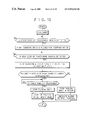
- FIG. 5 is a flow chart illustrating a printing routine including steps of checking a discernment code
- FIG. 6 is a flow chart illustrating another preferred embodiment in which the discernment code is checked upon a start of printing
- FIG. 7 is a flow chart illustrating still another preferred embodiment in which the discernment code is checked upon renewal of continuous recording sheet
- FIG. 8 is a block diagram illustrating a preferred embodiment having two printer units
- FIG. 9 is a block diagram illustrating a preferred embodiment having three printer units and three host computers.
- FIG. 10 is a perspective illustrating another preferred roll of continuous thermosensitive recording sheet together with cutters
- FIG. 11 is an explanatory view illustrating another preferred predetermined discernment code
- FIG. 12 is a plan illustrating still another preferred roll of continuous thermosensitive recording sheet with positioning indicia
- FIG. 13 is a flow chart illustrating a routine of positioning the recording sheet of FIG. 12 and including a code checking step
- FIG. 14 is a plan illustrating a further preferred roll of continuous thermosensitive recording sheet with positioning indicia and auxiliary indicia.
- a continuous recording sheet 10 as a recording material is wound about a reel 11 .
- a predetermined discernment code 13 is printed on a back surface of the continuous recording sheet 10 , and associated with each of printing regions 12 arranged in one train.
- the discernment code 13 is recorded also for the purpose of positioning of the printing regions 12 . According to a feeding amount of the continuous recording sheet 10 and a time point of detecting the discernment code 13 , a starting position of the printing regions 12 is detected exactly.
- the discernment code 13 is an 8-bit code including eight quadrilateral regions F 1 –F 8 , either dark color or blank, to represent eight bits b 0 , b 1 , . . . , b 7 .
- the bit b 0 at the first region F 1 constitutes a recording material type code.
- the recording material type code is either one of a simple thermosensitive sheet or a sticker sheet with thermosensitive layers. If the region F 1 is blank or white, then the bit b 0 is zero (0), to represent the simple thermosensitive sheet. If the region F 1 is dark color or black, then the bit b 0 is one (1), to represent the sticker sheet.
- the bits b 1 and b 2 at the regions F 2 and F 3 constitute a printing format code, which represents the multi-frame printing in which one common image is printed in plural regions arranged in a matrix on each single sheet, for example 4-region, 8-region, 16-region printing.
- the bits b 3 and b 4 at the regions F 4 and F 5 constitute a recording material size code, which represents the size of the recording sheet.
- a combination (0, 0) for the bits b 3 and b 4 represents the continuous form of the A 5 format.
- a combination (0, 1) represents the continuous form of the A 6 format.
- a combination (1, 0) represents the single cut sheet form of the A 5 format.
- a combination (1, 1) represents the single cut sheet form of the A 6 format.
- the bits b 5 , b 6 and b 7 at the regions F 6 , F 7 and F 8 constitute a recording material dealer code.
- the dealer code can have seven values of “0h” to “6h”, which represent seven dealers.
- a value “7h” is defined as an almighty code, which is not recorded to the continuous recording sheet.
- the almighty code is defined for use in the printer. If the dealer code in a reference code determined in the printer is “7h” as almighty code, then the continuous recording sheet is forcibly allowed for being used in printing in a manner irrespective of any particular dealer that the dealer code in the discernment code designates.
- the continuous recording sheet 10 is color thermosensitive recording sheet known in the art, and includes a base sheet material, cyan, magenta and yellow coloring layers, and a protective layer overlaid sequentially.
- the cyan coloring layer is disposed in the deepest position, has the lowest heat sensitivity, and colored in the cyan color upon application of relatively great heat energy.
- the magenta coloring layer is colored in the magenta color upon application of medium heat energy.
- the yellow coloring layer is disposed the farthest from the base sheet material, has the highest heat sensitivity, and colored in the yellow color upon application of relatively small heat energy.
- the protective layer is a transparent resin layer produced mainly from polyvinyl alcohol (PVA), and protects the coloring layers from being scratched or damaged.
- the yellow and magenta coloring layers have optical fixability, with which the colorability of those layers is destroyed upon application of electromagnetic rays so as to prevent their further coloring.
- the magenta coloring layer has the maximum absorption wavelength of approximately 365 nm. When the magenta coloring layer receives ultraviolet rays of this wavelength range, the magenta colorability is destroyed.
- the yellow coloring layer has the maximum absorption wavelength of approximately 420 nm. When the yellow coloring layer receives ultraviolet rays of this wavelength range, the yellow colorability is destroyed.
- a thermal printer 20 is schematically depicted as automatic portrait producing machine.
- the thermal printer 20 is constituted by a host computer 21 and a thermal printer unit 22 .
- the host computer 21 consists of a personal computer 24 , and includes a keyboard 24 b as an input unit, a display panel 25 and an external operation panel 26 .
- the keyboard 24 b is covered by a lid (not shown), which does not allow access to the keyboard 24 b when closed, but can be opened for allowing external operation of the keyboard 24 b.
- the cash detector unit 27 receives insertion of cash, counts the cash as inserted, and also pays out coins to be returned to a customer.
- the pick-up camera 28 photographs a body of the customer standing in front of the printer in a manner of a portrait.
- the host computer 21 controls sequential operation including the insertion of the cash and the ejection of print sheets.
- a menu is indicated on the display panel 25 .
- the customer operates the external operation panel 26 according to the menu, selects images to be combined, such as a background image, a foreground image, character images and decorative images, all as additional images 18 . See FIG. 3B .
- an image synthesis circuit 24 a produces information of a synthesized image to be printed.
- an auxiliary image memory 24 c is used for storing any of the additional images 18 to be combined with a principal image 16 of FIG. 3B picked up from the body of the customer.
- the printer unit 22 is constituted by various elements including a parallel control block 30 , a system control block 31 as an discriminator, a printing control block 32 or a pulse counter, a code reader 33 as an input unit, a thermal head 34 as a printing head, a sheet feeder 35 , and an optical fixer unit 36 .
- a platen roller 40 against which a heating element array 34 a of the thermal head 34 presses the continuous recording sheet 10 .
- the sheet feeder 35 includes feeder rollers 41 , a motor 42 for rotating the feeder rollers 41 , and a driver 43 for driving the motor 42 .
- the parallel control block 30 receives data from the host computer 21 including the image data and a printing start command signal, and transfers them to the system control block 31 . Also the parallel control block 30 transfers various status signals of the printer unit 22 to the host computer 21 .
- a frame memory 37 is included in the system control block 31 , and stores image data received from the host computer 21 .
- the system control block 31 controls the overall operation of the printer unit 22 .
- the printing control block 32 controls the thermal head 34 at the time of execution of printing, effects the image-processing, and controls the conveyance of the recording sheet.
- the host computer 21 when powered, sends a command signal to the printer unit 22 for reading of the discernment code.
- the code reader 33 is instructed to read the code by sending the command signal from the host computer 21 to the parallel control block 30 , the system control block 31 and the printing control block 32 in the printer unit 22 .
- the code reader 33 has a photo sensor 33 a or a recording material sensor, which optically reads the discernment code, and encodes the same.
- the predetermined discernment code as read is transferred to the system control block 31 , and written to a memory 38 .
- the code is kept stored in the memory 38 before the powering off of the printer.
- the host computer 21 effects a start-up operation, and sets the various elements in a ready mode, to stand by for awaiting customers.
- the ready mode the printing sequence and printed samples are indicated sequentially on the display panel.
- a customer inserts cash or coins of a predetermined amount into the cash detector unit 27 , so that the host computer 21 is set to a pick-up mode.
- the display panel 25 is caused to indicate a sequence of picking up images to be printed and a sequence of image synthesis.
- the external operation panel 26 is operated by the customer according to the indications, to cause the pick-up and image synthesis.
- the synthesized image is displayed, and confirmed by the customer's operation at the external operation panel 26 .
- the host computer 21 is set in a printing mode. In the printing mode, the host computer 21 transfers a printing command signal and data of an image to be printed to the printer unit 22 .
- the system control block 31 is controlled by the host computer 21 according to the parallel control, receives the image data, executes the reading of the discernment code, checks the discernment code with reference to the reference code, and starts printing.
- a reference code is sent by the host computer 21 via the parallel control block 30 to the system control block 31 for the purpose of a printing command and recording material discernment.
- the system control block 31 checks whether the reference code from the host computer 21 has a value of “7h”. If so, then the system control block 31 executes the printing operation.
- the printer unit 22 can be allowed to print in a manner irrespective of the type of the continuous recording sheet. Note that, if “7h” is initially desired for the reference code to be used, “7h” is input by use of the keyboard 24 b.
- the discernment code is read from the memory 38 .
- a recording material dealer code included in the discernment code is obtained, and checked as to whether it coincides with the recording material dealer code in the reference code. If there is coincidence, then the system control block 31 sends a printing command signal to the printing control block 32 , and transfers the image data required for being printed.
- the recording material type code, the recording material size code, the printing format code and the like in the discernment code are checked in a manner as to whether the continuous recording sheet 10 satisfies conditions suitable to be used in the printer unit 22 . If each of those codes coincide with a relevant part of the reference code, then the printing operation is started.
- the discernment code of the continuous recording sheet 10 to be used in the printer unit 22 is previously input in the personal computer 24 , so that the continuous recording sheet 10 having the coincidence in the discernment code is allowed for use in the printing.
- the continuous recording sheet 10 supplied by any dealer different from the particular dealer is rejected.
- the quality in the printing is ensured, as the continuous recording sheet 10 that is different from the standard continuous recording sheet or has been preserved under an unwanted condition is not used.
- the image data transferred from the host computer 21 is treated in the parallel control block 30 , and written to the frame memory 37 in the system control block 31 .
- the printing control block 32 operates for image processing according to a printing command signal from the system control block 31 , and transfers one-line yellow image data to the thermal head 34 from the image data after being processed, so as to drive each of the heating elements in the thermal head 34 . Also the printing control block 32 causes the sheet feeder 35 to convey the continuous recording sheet 10 by one line in synchronism with the driving of the thermal head 34 .
- the yellow image is recorded to the printing region 12 in the continuous recording sheet 10 one line after another. See FIG. 1 . Lines are similarly recorded one after another. After the yellow recording, the magenta and cyan are recorded, so that a full-color image is produced by the three-color frame-sequential recording.
- a yellow fixer lamp 36 a in the fixer unit 36 is turned on immediately after the yellow recording, to fix the yellow coloring layer.
- a magenta fixer lamp 36 b is turned on immediately after the magenta recording, to fix the magenta coloring layer. Note that, in the present embodiment, the thermal head 34 being single is used, and the continuous recording sheet 10 is conveyed back and forth. Furthermore, it is possible to record an image by the three-head one-pass recording, in which three thermal heads are used and the continuous recording sheet 10 is conveyed in one direction for one time.
- the system control block 31 transfers non-coincidence data to the host computer 21 without effecting the printing operation. Also for the recording material dealer code, the recording material type code, the recording material size code and the printing format code, coincidence is evaluated. The system control block 31 , when there is no coincidence, transfers data of non-coincidence to the host computer 21 . Then the host computer 21 causes the display panel 25 to indicate a printing disabled state due to the unacceptability of the continuous recording sheet 10 , and an alarm to call an attendant or operator. Also the host computer 21 causes a buzzer or a sound generator to generate an alarm sound. In the case where the cash has been inserted, the host computer 21 causes the cash detector unit 27 to pay back the cash to the customer without receipt.
- FIG. 6 another preferred embodiment is illustrated, in which the discernment code is read upon powering of the printer, to check coincidence of the discernment code with the reference code previously written. If there is no coincidence, then an alarm signal is generated in a visible manner to inform unacceptability of the continuous recording sheet 10 . Also the printing is inhibited. The alarm sound is generated for alarm to instruct an attendant or operator to insert acceptable continuous recording sheet. If there is coincidence, then the initial starting operation of the printer is executed, to set a ready mode in which the printer stands by for customers. In the ready mode, cash is insertable for pick-up of images, image synthesis, and printing.
- FIG. 7 a further preferred embodiment is illustrated, in which the discernment code is read and checked immediately after the renewal of the continuous recording sheet.
- the printing can be inhibited if the discernment code does not coincides with the reference code. If the reference code has the value “7h” of the almighty code, then the printing is allowed without reading the discernment code. Note that, in FIG. 6 , it is possible to add a step for checking whether the reference code has the value “7h” of the almighty code.
- the discernment code read by the code reader 33 is stored to the memory 38 at first, and read from the memory 38 at each time of printing, for the purpose of checking it with the reference code. Alternatively it is possible to read the discernment code at each time of printing.
- the system control block 31 in the printer unit 22 checks coincidence of the codes.
- the host computer 21 may operate for checking the coincidence of the discernment code with the reference code. For this operation, the discernment code being read is transferred from the printer unit 22 to the host computer 21 in a data form.
- the printer unit 22 does not operate for the checking of the coincidence, so that the load to the printer unit 22 can be reduced.
- the degree of freedom in applications on the side of the host computer 21 can be high.
- the reference code is stored in the host computer 21 .
- a non-volatile memory in the printer unit 22 , for example in the system control block 31 .
- the host computer 21 checks coincidence of the detected discernment code with the reference code.
- plural reference codes may be stored in the non-volatile memory. With such plural codes, printing may be allowed when the detected discernment code coincides with any one of the reference codes. Otherwise the printing is inhibited.
- the host computer 21 stores the reference code, store a plurality of reference codes in the host computer 21 .
- FIG. 8 another preferred thermal printer 53 is constituted by one host computer 50 and two thermal printer units 51 and 52 , and is operable as a multi-paper type.
- the printer unit 51 is used for printing with a simple thermosensitive sheet in a continuous form.
- the printer unit 52 is used for printing with a sticker sheet in a continuous form with thermosensitive layers.
- Each of the printer units 51 and 52 is allowed to operate only when acceptable recording material is set therein. Note that it is possible to construct a printer with three or more printer units.
- FIG. 9 a preferred embodiment is illustrated, in which three host computers 58 , 59 and 60 are used in connection respectively with thermal printer units 55 , 56 and 57 , so as to constitute a thermal printer 61 in a multi-paper manner. Only one of the plural continuous recording sheets is designated for printing by use of one of the host computers 58 , 59 and 60 and one of the printer units 55 , 56 and 57 .
- the discernment code 13 is disposed on the back surface of the continuous recording sheet 10 .
- FIG. 10 another preferred continuous recording sheet 66 as a recording material is illustrated.
- a predetermined discernment code 65 is printed on a printing surface of the continuous recording sheet 66 , and in a peripheral region 66 a outside an effective printing region 67 .
- Virtual cutting lines 68 are also predetermined on the continuous recording sheet 66 .
- the peripheral region 66 a with the discernment code 65 is cut away from the continuous recording sheet 66 by cutting along the virtual cutting lines 68 .
- a print sheet can be obtained with an agreeable appearance, as the discernment code 65 is eliminated from the continuous recording sheet 66 .
- the discernment code 65 is disposed close to a longitudinally extending edge of the continuous recording sheet 66 . Furthermore, it is possible to dispose a discernment code along a line which extends crosswise to the sheet feeding direction and will be an edge of each single sheet. Again, a small narrow portion having the discernment code can be cut off to provide the print sheet with good appearance.
- a cutter 72 is illustrated, which cuts the continuous recording sheet 66 into single pieces of print sheets.
- a cutter 74 cuts the continuous recording sheet 66 along each one of the virtual cutting lines 68 extending in the sheet feeding direction. Note that there is one more cutter (not shown) similar to the cutter 74 and disposed opposite to the cutter 74 .
- the recording material may be pieces of recording sheets.
- the discernment codes 13 and 65 may have a form of a bar code, a CALRA code or other optically readable codes.
- the number of bits of the discernment code may be different from eight (8), and may be changed in a manner suitable for the form of the used code.
- a clock code in parallel with the discernment code. A signal generated upon reading the clock code may be used for controlling the timing of reading each of the bits of the discernment code.
- the discernment code may be constructed with an electrically conducting pattern.
- a thermal printer may be provided with a brush for contacting the conducting pattern, for detecting the discernment code from the recording material.
- discernment information of the recording material may be magnetic.
- the recording material can be provided with a magnetic recording layer, to which the discernment information may be written magnetically.
- a predetermined set of holes or cutouts can be formed in the recording material in place of the quadrilateral regions F 1 –F 8 .
- the discernment code may be constituted by a permutation of the holes or cutouts selectively formed and arranged in one line.
- the discernment code 13 is a combination of the recording material dealer code, the recording material type code, the recording material size code and the printing format code.
- the discernment code may consist of only the recording material dealer code without other codes.
- a predetermined discernment code 70 may include a distribution channel code as illustrated in FIG. 11 for discernment of a distribution channel or distribution route of the continuous recording sheet.
- the discernment code 13 may consist of only the distribution channel code without other codes.
- each of the various codes have bits as illustrated in FIGS. 2 and 11 , the numbers of bits of each code may be changed suitably. Also, the sequence of arranging those various codes may be changed.
- the discernment code may be an identification code identifying the continuous recording sheet without discernment of the recording material dealer or the distribution channel.
- the distribution channel or distribution route of the recording material in the present embodiment means one of the wholesale dealer, the storehouse, the transportation agent and the transportation means, or other elements that treat the recording material in distribution from the manufacturer to the dealers, or combinations of any of those elements.
- the dealer code of the recording material coincides with that included in the reference code without checking any of the recording material type code, the recording material size code or the printing format code. Furthermore, it is possible to check only one of the recording material type code, the recording material size code and the printing format code, to determine either allowance or inhibition of printing. Also, it is possible to check a combined code constituting at least two of the dealer code, the recording material type code, the recording material size code and the printing format code.
- the recording material is a color recording sheet.
- the recording material in the present invention may be heat-development transfer type or sublimation thermal transfer type. Any recording material, of which quality is likely to change with time and due to a preserving condition, may be used in the present invention.
- the recording material may be a sheet for ink-jet printing, or photosensitive material of silver halide photography. For example, a self-processing photo film unit for use with an instant camera may be used.
- the discernment code 13 is disposed directly on the continuous recording sheet 10 . Also it is possible to dispose the discernment code 13 on any elements associated with the continuous recording sheet 10 . Examples of such elements are a recording sheet cassette or a recording sheet package for containing the continuous recording sheet 10 , axial ends of a recording sheet reel about which the continuous recording sheet 10 is wound in a roll form, and the like. In association with such elements, the printer is constructed to have a reader which reads the discernment code from a body of the cassette or package, or from the reel. In the above embodiments, the discernment code 13 is optically readable. Also, the discernment information may be data written to an IC memory.
- the discernment code is read automatically. However it is possible to input the discernment code manually by operating the keyboard 24 b of the personal computer 24 depicted in FIG. 3A at the time of setting the continuous recording sheet in the printer.
- the keyboard 24 b is unlike the external operation panel 26 , as the keyboard 24 b is not externally accessible. A lid (not shown) of the printer must be opened for renewing the continuous recording sheet before the keyboard 24 b can become operable.
- the printing is allowed when the discernment code coincides with the reference code. If there is no coincidence, the printing is inhibited.
- the discernment code 13 is prerecorded respectively with the printing region 12 at a predetermined pitch, and can be used also as a positioning indicia with which the printing region 12 is positioned.
- the continuous recording sheet 10 may have only one discernment code prerecorded on a front end of the continuous recording sheet 10 . See FIG. 1 .
- the discernment code 13 may be disposed regularly at a certain pitch which is not related to the pitch of the printing region 12 .
- the printing is inhibited and an alarm signal is generated when the discernment code 13 does not coincide with the reference code.
- the printing may be inhibited without generating an alarm signal.
- an alarm signal may be generated without inhibiting the printing operation.
- FIG. 12 another preferred continuous recording sheet 76 as a recording material is illustrated, and is provided with a positioning indicia 75 .
- the continuous recording sheet 76 has a virtual cutting line 77 , an effective printing region 78 and a reel 79 .
- the positioning indicia 75 is used also to represent predetermined discernment information.
- the positioning indicia 75 is printed in the course of manufacturing the continuous recording sheet 76 in a predetermined length and shape. In the printer, the positioning indicia 75 is checked as to whether the positioning indicia 75 has the predetermined length.
- the printer has an indicia sensor 84 , which detects edges of the positioning indicia 75 according to the sheet feeding direction.
- the length data X 1 is compared with the reference data A, which is the predetermined number of pulses. If the length data X 1 satisfies 0.9A ⁇ X 1 ⁇ 1.1A namely if the length data X 1 is in a range of ⁇ 10% of reference data A, then the continuous recording sheet 76 is detected to be usable. If the length data X 1 does not satisfy the condition, the printing is inhibited, an alarm signal is generated. See FIG. 13 . Note that a tolerable range of the length data X 1 is ⁇ 10% of reference data A. This may be suitably modified. In the present embodiment, the length data X 1 is determined by use of the number of pulses. However, other manners of representing a length of the positioning indicia 75 may be used.
- a distance between adjacent two of the positioning indicia 75 is obtained, and compared with a reference value B in consideration of a small tolerable range, so as to check acceptability of the recording material.
- the distance between adjacent two positioning indicia 75 means a distance from a rear edge of a first positioning indicia 75 to a front edge of a second positioning indicia 75 succeeding to the first.
- Distance data Y 1 of this distance is obtained as the number of driving pulses generated after detection of the rear edge of the first positioning indicia 75 at the indicia sensor 84 and before detection of the front edge of the second positioning indicia 75 at the indicia sensor 84 .
- the distance data Y 1 of the positioning indicia 75 may be a pitch between adjacent two of the positioning indicia 75 .
- the number of the driving pulses of the stepping motor is counted in a period starting at a front edge of one of the positioning indicia 75 and ending at a front edge of a succeeding one of the positioning indicia 75 , so as to obtain distance data.
- the recording material is detected acceptable in view of the reference information.
- FIG. 14 still another preferred embodiment is illustrated, in which an auxiliary indicia 81 is disposed on a continuous recording sheet 82 as a recording material.
- Distance data Z 1 between the auxiliary indicia 81 and a positioning indicia 80 is obtained for the purpose of checking acceptability of the continuous recording sheet 82 .
- the distance data Z 1 in a manner similar to the above embodiment, is obtained according to a signal detecting an edge at the indicia sensor 84 , and the number of driving pulses for the stepping motor.
- Reference data C is predetermined. Only when the distance data Z 1 is equal to the reference data C or in a predetermined tolerable range defined near to the reference data C, then the continuous recording sheet 82 is detected acceptable.
- the distance data Z 1 can be combined with the length data X 1 , so that their combination may be evaluated in consideration of reference information.
- the recording material can be checked for acceptability.
- the number of driving pulses supplied for the stepping motor is counted for obtaining data X 1 , Y 1 and Z 1 .
- a pulse encoder may be disposed in a manner rotatable in response to movement of the continuous recording sheet. An output of the pulse encoder may be monitored to obtain the data X 1 , Y 1 and Z 1 .
- a width data W 1 of the positioning indicia 75 is evaluated as discernment information.
- a thermal printer is constructed to include a line sensor or image area sensor as the indicia sensor 84 , which measures the width data W 1 in addition to detection of edges of the positioning indicia 75 . The printer checks whether the width data W 1 is in a reference range based on a reference width, and if it is, then the recording material is detected acceptable. Note that the width data W 1 can be combined with any one of the length data X 1 , and the distance data Y 1 and Z 1 , so that their combination may be evaluated in consideration of reference information.
- the shape of the positioning indicia may be predetermined and associated with information.
- An image area sensor can be used to recognize the shape of the positioning indicia in a manner of the pattern recognition. If the positioning indicia is detected to coincide with a reference indicia, then the continuous recording sheet can be detected acceptable.
- the shape of the positioning indicia is double quadrilateral frame lines, a combined shape including a dark quadrilateral and a blank quadrilateral formed therein, a combined shape including a dark quadrilateral and a blank circle therein, and a combined shape including a dark quadrilateral and a blank star polygon therein.
- the positioning indicia 75 and 80 and the auxiliary indicia 81 are printed.
- such indicia may be defined by forming holes or cutouts in the recording material. Those holes and cutouts must be disposed in a peripheral region outside an effective printing region.
- the positioning indicia 75 is used for checking suitability of the continuous recording sheet for the printing component. Furthermore, plural kinds of positioning indicia may be disposed, and may have a length, a width, a pitch or the like different between them. Such positioning indicia may be associated with plural predetermined recording material dealer codes or distribution channel codes for the purpose of recognizing dealers and the distribution channel or distribution routes. If some code as a part of the discernment code does not coincide with a relevant part of the reference code, then the printing is inhibited and/or an alarm signal is generated.
- the discernment information of the recording material is the code.
- the discernment information may be words, phrases, letters, numbers and other readable indications.
- a code reader may be an image area sensor or scanner.
- the discernment information is prerecorded on, and read from, the recording material.
- the discernment information may be derived from the recording material by any suitable manner. For example, a certain characteristic of the recording material may be directly measured or detected to derive information from the recording material.
- the reference code or reference information has the same form as the discernment code or discernment information. Equality or coincidence between them is checked.
- the reference code or reference information may have a form different from that of the discernment code or discernment information, for example may have a train of decimal numbers, so that the discernment code or discernment information can be evaluated as to whether it suitably corresponds to such reference code or reference information.
- coins or banknotes are inserted.
- a unit for automatically treating a prepaid card, a credit card or electronic money may be disposed for the purposes of payment and return of money.
Abstract
Description
0.9A≦X1≦1.1A
namely if the length data X1 is in a range of ±10% of reference data A, then the
Claims (40)
Applications Claiming Priority (1)
| Application Number | Priority Date | Filing Date | Title |
|---|---|---|---|
| JP23097298 | 1998-08-17 |
Publications (1)
| Publication Number | Publication Date |
|---|---|
| US6934043B1 true US6934043B1 (en) | 2005-08-23 |
Family
ID=34835715
Family Applications (1)
| Application Number | Title | Priority Date | Filing Date |
|---|---|---|---|
| US09/373,589 Expired - Fee Related US6934043B1 (en) | 1998-08-17 | 1999-08-13 | Printer and recording material for the same |
Country Status (1)
| Country | Link |
|---|---|
| US (1) | US6934043B1 (en) |
Cited By (7)
| Publication number | Priority date | Publication date | Assignee | Title |
|---|---|---|---|---|
| US20030164974A1 (en) * | 2002-02-20 | 2003-09-04 | Fuji Photo Film Co., Ltd. | Information conveyance system and printing medium having IC chips |
| US20050147452A1 (en) * | 2004-01-06 | 2005-07-07 | Brother Kogyo Kabushiki Kaisha | Label printer and printing medium |
| US20080175645A1 (en) * | 2001-12-14 | 2008-07-24 | Sony Corporation | Printer and roll-shaped printing medium therefor |
| WO2015136397A1 (en) * | 2014-03-12 | 2015-09-17 | Custom S.P.A. | Printing device and method for controlling the printing device |
| US9676216B2 (en) | 2014-03-27 | 2017-06-13 | Datamax-O'neil Corporation | Systems and methods for automatic printer configuration |
| CN112698761A (en) * | 2020-12-30 | 2021-04-23 | 维沃移动通信有限公司 | Image display method and device and electronic equipment |
| EP3597444B1 (en) * | 2017-03-22 | 2023-12-27 | Kabushiki Kaisha Toshiba | Recording medium |
Citations (5)
| Publication number | Priority date | Publication date | Assignee | Title |
|---|---|---|---|---|
| US4782221A (en) * | 1985-04-01 | 1988-11-01 | Cauzin Systems, Incorporated | Printed data strip including bit-encoded information and scanner control |
| US5053814A (en) * | 1986-12-24 | 1991-10-01 | Minolta Camera Kabushiki Kaisha | Image forming apparatus |
| US5816165A (en) * | 1997-02-10 | 1998-10-06 | Hewlett-Packard Company | Method of encoding roll length indicia on printer media |
| US6246776B1 (en) * | 1999-01-19 | 2001-06-12 | Xerox Corporation | Image recording media determination system, apparatus and method for an image processing device |
| US6335084B1 (en) * | 1998-12-30 | 2002-01-01 | Xerox Corporation | Encoded sheet material and sheet processing apparatus using encoded sheet material |
-
1999
- 1999-08-13 US US09/373,589 patent/US6934043B1/en not_active Expired - Fee Related
Patent Citations (5)
| Publication number | Priority date | Publication date | Assignee | Title |
|---|---|---|---|---|
| US4782221A (en) * | 1985-04-01 | 1988-11-01 | Cauzin Systems, Incorporated | Printed data strip including bit-encoded information and scanner control |
| US5053814A (en) * | 1986-12-24 | 1991-10-01 | Minolta Camera Kabushiki Kaisha | Image forming apparatus |
| US5816165A (en) * | 1997-02-10 | 1998-10-06 | Hewlett-Packard Company | Method of encoding roll length indicia on printer media |
| US6335084B1 (en) * | 1998-12-30 | 2002-01-01 | Xerox Corporation | Encoded sheet material and sheet processing apparatus using encoded sheet material |
| US6246776B1 (en) * | 1999-01-19 | 2001-06-12 | Xerox Corporation | Image recording media determination system, apparatus and method for an image processing device |
Cited By (15)
| Publication number | Priority date | Publication date | Assignee | Title |
|---|---|---|---|---|
| US20080175645A1 (en) * | 2001-12-14 | 2008-07-24 | Sony Corporation | Printer and roll-shaped printing medium therefor |
| US20030164974A1 (en) * | 2002-02-20 | 2003-09-04 | Fuji Photo Film Co., Ltd. | Information conveyance system and printing medium having IC chips |
| US7602519B2 (en) | 2002-02-20 | 2009-10-13 | Fujifilm Corporation | Information conveyance system and printing medium having IC chips |
| US20080056800A1 (en) * | 2004-01-06 | 2008-03-06 | Brother Kogyo Kabushiki Kaisha | Label printer and printing medium |
| US7318680B2 (en) * | 2004-01-06 | 2008-01-15 | Brother Kogyo Kabushiki Kaisha | Label printer and printing medium |
| US7559713B2 (en) | 2004-01-06 | 2009-07-14 | Brother Kogyo Kabushiki Kaisha | Label printer and printing medium |
| US20050147452A1 (en) * | 2004-01-06 | 2005-07-07 | Brother Kogyo Kabushiki Kaisha | Label printer and printing medium |
| WO2015136397A1 (en) * | 2014-03-12 | 2015-09-17 | Custom S.P.A. | Printing device and method for controlling the printing device |
| CN106170394A (en) * | 2014-03-12 | 2016-11-30 | 柯斯特姆股份公司 | Printing equipment and the method controlling printing equipment |
| US9782985B2 (en) | 2014-03-12 | 2017-10-10 | Custom S.P.A. | Printing device and method for controlling the printing device |
| RU2678891C2 (en) * | 2014-03-12 | 2019-02-04 | Кастом С.П.А. | Printing device and method for controlling printing device |
| CN106170394B (en) * | 2014-03-12 | 2019-05-17 | 柯斯特姆股份公司 | Printing equipment and the method for controlling printing equipment |
| US9676216B2 (en) | 2014-03-27 | 2017-06-13 | Datamax-O'neil Corporation | Systems and methods for automatic printer configuration |
| EP3597444B1 (en) * | 2017-03-22 | 2023-12-27 | Kabushiki Kaisha Toshiba | Recording medium |
| CN112698761A (en) * | 2020-12-30 | 2021-04-23 | 维沃移动通信有限公司 | Image display method and device and electronic equipment |
Similar Documents
| Publication | Publication Date | Title |
|---|---|---|
| US6674456B2 (en) | Printer and printing method capable of double-sided printing | |
| US6099178A (en) | Printer with media supply spool adapted to sense type of media, and method of assembling same | |
| US6634814B2 (en) | Printer media supply spool adapted to allow the printer to sense type of media, and method of assembling same | |
| US6529288B1 (en) | Digital printing system | |
| US6934043B1 (en) | Printer and recording material for the same | |
| US6344891B1 (en) | Printer usable with recording material of plural types | |
| EP1013455B1 (en) | A printer with donor and receiver media supply trays each adapted to allow a printer to sense type of media therein, and method of assembling the printer and trays | |
| JP4334329B2 (en) | recoding media | |
| JP2000127551A (en) | Printer and recording sheet | |
| JP3357119B2 (en) | Label printing method in label printer | |
| JP2003099718A (en) | Device and method for preparing id card | |
| US6091510A (en) | Journal device which facilitates retrieval of data printed on journal paper | |
| JP2020138550A (en) | Printer, recording medium, and sales data processing device | |
| JP3193461B2 (en) | Ticketing system | |
| JPH054227B2 (en) | ||
| JP2000158777A (en) | Printer, ribbon cartridge and use restriction method for ribbon cartridge | |
| JP2976646B2 (en) | Passbook printer | |
| KR940009721B1 (en) | Portable recording card for protecting counterfeit and it's reading and writing apparatus and method | |
| JP6354161B2 (en) | Card forming medium, printer, card issuing device | |
| JP2963755B2 (en) | Recording device | |
| EP0622679A1 (en) | Photographic processing method | |
| JPH0738998Y2 (en) | Card reader / printer with transfer card issuing function | |
| JP2000259770A (en) | Device and method for checking card body | |
| JPH08320953A (en) | Method for detecting high temperature abnormality for thermal printer and thermal head | |
| JPS6214299A (en) | Goods receiver |
Legal Events
| Date | Code | Title | Description |
|---|---|---|---|
| AS | Assignment |
Owner name: FUJI PHOTO FILM CO., LTD., JAPAN Free format text: ASSIGNMENT OF ASSIGNORS INTEREST;ASSIGNORS:SUGIYAMA, NAOSHI;ASANO, MOTOSHIGE;FUJIMAKI, TOSHIAKI;AND OTHERS;REEL/FRAME:010174/0106;SIGNING DATES FROM 19990708 TO 19990718 |
|
| AS | Assignment |
Owner name: FUJIFILM CORPORATION, JAPAN Free format text: ASSIGNMENT OF ASSIGNORS INTEREST;ASSIGNOR:FUJIFILM HOLDINGS CORPORATION (FORMERLY FUJI PHOTO FILM CO., LTD.);REEL/FRAME:018904/0001 Effective date: 20070130 Owner name: FUJIFILM CORPORATION,JAPAN Free format text: ASSIGNMENT OF ASSIGNORS INTEREST;ASSIGNOR:FUJIFILM HOLDINGS CORPORATION (FORMERLY FUJI PHOTO FILM CO., LTD.);REEL/FRAME:018904/0001 Effective date: 20070130 |
|
| FEPP | Fee payment procedure |
Free format text: PAYOR NUMBER ASSIGNED (ORIGINAL EVENT CODE: ASPN); ENTITY STATUS OF PATENT OWNER: LARGE ENTITY |
|
| FPAY | Fee payment |
Year of fee payment: 4 |
|
| REMI | Maintenance fee reminder mailed | ||
| LAPS | Lapse for failure to pay maintenance fees | ||
| STCH | Information on status: patent discontinuation |
Free format text: PATENT EXPIRED DUE TO NONPAYMENT OF MAINTENANCE FEES UNDER 37 CFR 1.362 |
|
| FP | Lapsed due to failure to pay maintenance fee |
Effective date: 20130823 |