US6949741B2 - Atmospheric pressure ion source - Google Patents
Atmospheric pressure ion source Download PDFInfo
- Publication number
- US6949741B2 US6949741B2 US10/732,205 US73220503A US6949741B2 US 6949741 B2 US6949741 B2 US 6949741B2 US 73220503 A US73220503 A US 73220503A US 6949741 B2 US6949741 B2 US 6949741B2
- Authority
- US
- United States
- Prior art keywords
- electrode
- carrier gas
- analyte
- atmospheric pressure
- chamber
- Prior art date
- Legal status (The legal status is an assumption and is not a legal conclusion. Google has not performed a legal analysis and makes no representation as to the accuracy of the status listed.)
- Ceased, expires
Links
Images


Classifications
-
- H—ELECTRICITY
- H01—ELECTRIC ELEMENTS
- H01J—ELECTRIC DISCHARGE TUBES OR DISCHARGE LAMPS
- H01J49/00—Particle spectrometers or separator tubes
- H01J49/02—Details
- H01J49/10—Ion sources; Ion guns
- H01J49/14—Ion sources; Ion guns using particle bombardment, e.g. ionisation chambers
- H01J49/147—Ion sources; Ion guns using particle bombardment, e.g. ionisation chambers with electrons, e.g. electron impact ionisation, electron attachment
-
- G—PHYSICS
- G01—MEASURING; TESTING
- G01N—INVESTIGATING OR ANALYSING MATERIALS BY DETERMINING THEIR CHEMICAL OR PHYSICAL PROPERTIES
- G01N27/00—Investigating or analysing materials by the use of electric, electrochemical, or magnetic means
- G01N27/62—Investigating or analysing materials by the use of electric, electrochemical, or magnetic means by investigating the ionisation of gases, e.g. aerosols; by investigating electric discharges, e.g. emission of cathode
- G01N27/622—Ion mobility spectrometry
- G01N27/623—Ion mobility spectrometry combined with mass spectrometry
-
- H—ELECTRICITY
- H01—ELECTRIC ELEMENTS
- H01J—ELECTRIC DISCHARGE TUBES OR DISCHARGE LAMPS
- H01J49/00—Particle spectrometers or separator tubes
-
- H—ELECTRICITY
- H01—ELECTRIC ELEMENTS
- H01J—ELECTRIC DISCHARGE TUBES OR DISCHARGE LAMPS
- H01J49/00—Particle spectrometers or separator tubes
- H01J49/02—Details
- H01J49/04—Arrangements for introducing or extracting samples to be analysed, e.g. vacuum locks; Arrangements for external adjustment of electron- or ion-optical components
- H01J49/0459—Arrangements for introducing or extracting samples to be analysed, e.g. vacuum locks; Arrangements for external adjustment of electron- or ion-optical components for solid samples
-
- H—ELECTRICITY
- H01—ELECTRIC ELEMENTS
- H01J—ELECTRIC DISCHARGE TUBES OR DISCHARGE LAMPS
- H01J49/00—Particle spectrometers or separator tubes
- H01J49/02—Details
- H01J49/10—Ion sources; Ion guns
-
- H—ELECTRICITY
- H05—ELECTRIC TECHNIQUES NOT OTHERWISE PROVIDED FOR
- H05H—PLASMA TECHNIQUE; PRODUCTION OF ACCELERATED ELECTRICALLY-CHARGED PARTICLES OR OF NEUTRONS; PRODUCTION OR ACCELERATION OF NEUTRAL MOLECULAR OR ATOMIC BEAMS
- H05H1/00—Generating plasma; Handling plasma
- H05H1/24—Generating plasma
- H05H1/26—Plasma torches
- H05H1/32—Plasma torches using an arc
- H05H1/34—Details, e.g. electrodes, nozzles
- H05H1/3447—Rod-like cathodes
-
- H—ELECTRICITY
- H05—ELECTRIC TECHNIQUES NOT OTHERWISE PROVIDED FOR
- H05H—PLASMA TECHNIQUE; PRODUCTION OF ACCELERATED ELECTRICALLY-CHARGED PARTICLES OR OF NEUTRONS; PRODUCTION OR ACCELERATION OF NEUTRAL MOLECULAR OR ATOMIC BEAMS
- H05H1/00—Generating plasma; Handling plasma
- H05H1/24—Generating plasma
- H05H1/47—Generating plasma using corona discharges
-
- H—ELECTRICITY
- H01—ELECTRIC ELEMENTS
- H01J—ELECTRIC DISCHARGE TUBES OR DISCHARGE LAMPS
- H01J49/00—Particle spectrometers or separator tubes
- H01J49/02—Details
- H01J49/10—Ion sources; Ion guns
- H01J49/14—Ion sources; Ion guns using particle bombardment, e.g. ionisation chambers
Definitions
- Metastable atoms and molecules are excited-state species with long lifetimes. Metastable species are produced in corona or glow electrical discharges. Other methods of producing excited-state species include electron impact, photoionization, and controlled interaction of high energy particles with a reactant species. Collisions between excited-state species and ground-state species can result in ionization of the ground-state species and release of electrons by a process known as Penning ionization, for example: M*+N ⁇ >N + +M+e ⁇ Equation 1
- Radioactive materials such as 63 Ni, 241 Am, and 3 H, among others, have led to a search for non-radioactive ion sources for analytical instruments, such as ion mobility spectrometers.
- analytical instruments such as ion mobility spectrometers.
- ion mobility spectrometers See Turner et al. U.S. Pat. No. 6,225,623 entitled “Corona Discharge Ion Source for Analytical Instruments” and Doring U.S. Patent Application Publication No. 2002/0185593 entitled “Ion Mobility Spectrometer with Non-Radioactive Ion Source”.
- a corona discharge in air leads to the formation of species, such as NO 2 ⁇ , NO 3 ⁇ , and related cluster ions. These ions can cause a loss of sensitivity for analyte ions (C. A. Hill and C. L. P. Thomas, Analyst, 2003, 128, pp. 55-60) and can interfere with the detection of NO 2 ⁇ and NO 3 ⁇ produced from analytes containing nitro functional groups, such as nitro explosives or in the case of chloride ion interference with chlorate propellants and rocket motors or phosphate interference with chemical warfare-related compounds.
- species such as NO 2 ⁇ , NO 3 ⁇ , and related cluster ions.
- U.S. Pat. No. 6,124,675 entitled “Metastable Atom Bombardment Source” discloses a metastable atom source operating at reduced pressure for generating ions in a mass spectrometer.
- the device described requires substantially reduced pressures and does not describe means for using metastable atoms for atmospheric pressure ionization mass spectrometry or ion mobility spectrometers.
- the present invention provides a means of sampling neutral analyte molecules without the restriction of relocating the analyte from the surfaces on which they are attached.
- cocaine from cash currency, and chemical/biological warfare agents from surfaces of military interest can be sampled directly and in situ without swabbing or solvent washing the surface.
- analyte molecules are lost (30 to 100% for trace-level concentrations). Therefore, direct surface sampling is always preferred.
- an atmospheric pressure ionization source or interface comprising: a first atmospheric pressure chamber having an inlet for carrier gas, a first electrode, and a counter-electrode for creating a corona or glow electric discharge in the carrier gas causing the formation of neutral excited-state metastable species; a second atmospheric pressure chamber having a port in communication with the first chamber; and an optional third atmospheric pressure chamber having a port in communication with the second chamber, there being a lens electrode about said port between the second and third chambers, the third chamber having an outlet port for the carrier gas and an optional electrode at the outlet port.
- the discharge is confined to the first chamber.
- the first electrode and ports are substantially aligned.
- a power supply is provided for maintaining selected potentials on each electrode.
- the third chamber may advantageously be an elongated glass tube that is removably inserted into a socket in the second chamber.
- the atmospheric pressure source or interface can be used to form positive or negative ions for use with spectrometers or other instruments which operate in the positive or negative ion mode.
- negative and positive ions are both formed when the analyte is brought into contact with the excited state species.
- Some analytes are electrophilic and tend to capture electrons to produce negatively charged analyte ions that allow detection and identification of these analytes.
- Others have a greater affinity for protons or positive ions and become ionized by picking up a proton [M+H] + ,for example. This will guide the selection of an instrument in a positive or negative ion mode.
- the power supply permits the lens electrode and the electrode at the outlet port to switch polarity without switching the polarity of the first electrode and the counter-electrode.
- the first electrode and counter-electrode must be maintained at potentials sufficient to induce an electrical discharge.
- the counter-electrode also serves to filter ionized species.
- the potential difference between the first electrode and counter-electrode necessary for the formation of a discharge depends on the carrier gas and the shape of the first electrode, and is usually several hundreds of volts, say 400 or 1,200. But for small electron structures such as those used in flat-screen plasma TV's, a few volts is sufficient.
- the first electrode for example, a needle electrode, may have either a positive or negative potential.
- the counter-electrode is normally grounded or of polarity opposite to the needle electrode. This is the case whether operating in the positive ion or negative ion mode.
- the lens electrode In the positive ion mode, the lens electrode may be between ground potential and a few hundred positive volts to filter out negative ions in the carrier gas. Also, in the negative ion mode, the lens electrode may be between ground and minus a few hundred volts to filter out positive ions in the carrier gas.
- the apparatus described in the preceding paragraph is placed with the outlet of the third chamber close to the entrance of a charged particle detector in a positive ion mode, such as a mass spectrometer, an ion mobility spectrometer, or a chemical agent monitor.
- a positive ion mode such as a mass spectrometer, an ion mobility spectrometer, or a chemical agent monitor.
- the electrodes are placed in the positive ion mode.
- the gas containing excited-state species emerging from the outlet port of the third chamber is directed through or at an analyte positioned near the entrance to the detector operated in the positive ion mode.
- the metastable species in the carrier gas react with the analyte to form positive ions for analysis.
- Analyte molecules undergo ion molecule reactions to form species such as [M+H] + .
- the form of the analyte may be a vapor from an open vial, in solid form on a surface, or in the form of an aspirated liquid, for example.
- the apparatus described above is placed with the outlet of the third chamber close to the entrance to a charged particle detector.
- the electrodes are placed in the negative ion mode.
- the gas containing exited-state species emerging from the outlet port of the third chamber is directed through or at an analyte positioned near the entrance to the detector operated in the negative ion mode.
- the metastable species in the carrier gas react with the analyte to form negative ions for analysis.
- the form of the analyte may be a vapor from an open vial, in solid form on a surface, or in the form of an aspirated material, for example.
- the apparatus described above is used in a “sniffer” mode with the outlet of the third chamber close to the entrance of a charged particle detector.
- the electrode at the outlet may comprise a grid and is maintained at ground or negative potential or at an AC potential offset by a DC voltage to induce dissociation of the reactive species to provide a source of electrons as the metastable species collide with the grid.
- the resulting electrons are rapidly cooled (slowed) to thermal energies by collisions with the gas molecules.
- the electrodes are placed in the negative ion mode.
- the gas containing electrons emerging from the outlet port of the third chamber is directed through or at an atmospheric pressure analyte not in an intense electric field and positioned near the entrance to a charged particle detector, such as a mass spectrometer or ion mobility spectrometer, either of which is operated in the negative ion mode.
- a charged particle detector such as a mass spectrometer or ion mobility spectrometer, either of which is operated in the negative ion mode.
- the electrons in the carrier gas are captured by the analyte to form negative ions that are cooled by gas collisions.
- the form of the analyte may be a vapor from an open vial, in solid form on a surface, or in the form of a static or aspirated liquid, for example.
- a fourth embodiment is similar to the third “sniffer” mode embodiment except that the grid electrode is maintained positive and the gas emerging from the outlet forms positive ions with the analyte for analysis in the positive ion mode.
- an atmospheric pressure ionization source or interface comprising: a first atmospheric pressure chamber having an inlet for carrier gas, an electrode therein, and a counter-electrode for creating a corona or glow discharge in the carrier gas creating metastable species, ions, electrons, hot atoms and molecules, and radicals; a second atmospheric pressure chamber adjacent the first chamber having a port into the first chamber and having an optional inlet and optional outlet for cooling or reactant gases; and a third atmospheric pressure chamber adjacent the second chamber having a port into the second chamber and having an inlet for analyte gas and an outlet port for ionized products of the interaction of the metastable species and the analyte gas, the electrode and ports being substantially aligned.
- an atmospheric pressure ionization source or interface comprising: a first chamber having an inlet for carrier gas, an electrode therein, and a counter-electrode for creating a glow or corona discharge in the carrier gas creating metastable species; and a second chamber adjacent the first chamber having an outlet port for electrons and/or metastable species, the electrode and ports being substantially aligned.
- atmospheric pressure in this specification and the appended claims is meant pressures near ambient pressures, say 400 to 1,400 Torr. This would include pressurized aircraft and submerged submarines. For laboratory use, ambient pressures may fall within the range 700 to 800 Torr.
- the carrier gas may be heated prior to introduction into the interface or while in the interface to facilitate vaporization or desorption of the analyte into the gas phase from surfaces. It is preferable to provide an adjustable regulator for adjusting the gas pressure to control the speed of ionizing electron energy since electrons embedded in the gas stream will be carried along and accelerated by changing gas pressures. Energy resolved spectra may be achieved in this fashion.
- FIG. 1 is a schematic diagram of an atmospheric pressure source comprising aligned chambers C 1 , C 2 , and C 3 according to the present invention
- FIG. 2 is a schematic diagram of the atmospheric pressure source associated with a mass spectrometer
- FIG. 3 is a schematic diagram of an atmospheric pressure source or device comprising three chambers followed by a grid for converting metastable species to electrons;
- FIG. 4 is a schematic diagram of a simplified atmospheric pressure device having only two chambers
- FIG. 5 is a perspective view of an atmospheric pressure interface or device according to the present invention at scale 2:1;
- FIG. 6 is a broken away perspective view similar to FIG. 5 ;
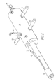
- FIG. 7 is a detail from the perspective view of FIG. 6 ;
- FIG. 8 is a schematic circuit diagram of a power supply for an atmospheric pressure device or source according to the present invention.
- FIG. 9 is a mass spectrum of nitrogen carrier gas introduced into the discharge region of chamber C 1 of FIG. 2 ;
- FIG. 10 is a mass spectrum wherein room air is introduced into the nitrogen carrier gas stream in chamber C 1 of FIG. 2 ;
- FIG. 11 is a mass spectrum wherein room air is introduced into chamber C 3 of FIG. 2 ;
- FIG. 12 is a mass spectrum of diethylmethylphosphonothiolate introduced into chamber C 3 ;
- FIG. 13 is a mass spectrum of hexafluorobenzene introduced into chamber C 3 ;
- FIG. 14 is a mass spectrum similar to that of FIG. 9 wherein background ions have been eliminated;
- FIG. 15 is a mass spectrum wherein air is introduced into chamber C 3 ;
- FIG. 16 is a mass spectrum wherein nitrobenzene is introduced into chamber C 3 ;
- FIGS. 17 and 18 are positive ion mass spectra for nitromethane and nitrobenzene, respectively;
- FIG. 19 is a mass spectrum of air using the interface shown schematically in FIG. 3 ;
- FIG. 20 is a mass spectrum of ethymethyphosphonate using the interface shown schematically in FIG. 3 ;
- FIG. 21 is a mass spectrum of diethylmethylphosphonate (DEMP) using the interface shown schematically in FIG. 3 ;
- FIG. 22 is a mass spectrum of DEMP (positive ion) using the interface shown schematically in FIG. 3 ;
- FIG. 23 is a mass spectrum of TNT (negative ion) using the interface shown schematically in FIG. 3 ;
- FIG. 24 ( a ) is a mass spectrum of TNT deposited on an airline-boarding pass and FIG. 24 ( b ) is the mass spectrum from the same boarding pass. Positive variations away from the baseline occur when a boarding pass is brought into the vicinity of the source.
- FIG. 1 A generalized implementation of the present invention is shown schematically in FIG. 1 .
- This device provides an electrode N, for example, a needle electrode, to which an electrical potential can be applied in a first atmospheric pressure chamber C 1 into which a carrier gas can be introduced through gas inlet G 1 and flow out of a gas-closeable outlet O 1 .
- the electrode N may be a point, line, plane, or curved-shape electrode.
- a needle electrode is an example of a point electrode
- a trim blade is an example of a line electrode.
- the counter-electrode E 0 contains a hole through which gas and charged particles can pass. It is set to a potential (for example, ground potential) that allows a corona or glow electrical discharge to be established between the electrode N and counter-electrode E 0 .
- the electrode may be either a cathode establishing a negative potential or an anode establishing a positive potential. In the electrical discharge, positive ions, electrons, and metastable excited-state atoms are formed.
- An additional electrode El is placed at the exit of an optional second chamber C 2 with closeable gas inlet G 2 and closeable gas outlet O 2 . Electrode E 1 also defines the entrance to third chamber C 3 where a final electrode E 2 is positioned at the exit.
- carrier gas is introduced from a gas cylinder into chamber C 1 at a positive pressure. This causes flow of metastable excited-state atoms into chambers C 2 and C 3 .
- the chambers have a volume of about one cubic centimeter.
- the orifices between chambers are about 3 mm in diameter and the flow through the orifices is on the order of a few milliliters per minute.
- the carrier gases that have been used by the Applicants are helium and nitrogen.
- P-10 gas (90% argon +10% methane) and He/Ne mixtures are potential carrier gases.
- argon and krypton are potential carrier gases. Indeed, any gas or mixture of gases with a metastable state lying higher than a state of the analyte is a potential carrier gas.
- the corona or glow electrical discharge occurs in chamber C 1 .
- Chamber C 2 provides an optional buffer region between chambers C 1 and C 3 , and provides an option for introducing a separate cooling gas or a reactant gas.
- Cooling gases comprise, for example, gases that would be ionized by metastable atoms to produce a positive ion and electron. The electron would be thermalized by further collisions.
- Carbon dioxide, methane, and air are examples of cooling gases.
- Reactive gases are those that favor distinctive ion peaks by ion-molecule reactions.
- a small amount of reactive gas such as ammonia (to promote ammonium ion attachment for positive ions), or a gas that produces chloride ions (e.g., methylene chloride, chloroform, or carbon tetrachloride for negative ions), can be added to the cooling gas.
- Chloride ion addition has been shown to drastically enhance the detection of polynitro explosives by several orders of magnitude.
- the analyte may be introduced into chamber C 3 and ions of analyte are extracted through a port in electrode E 2 into the mass spectrometer atmospheric pressure interface or into the ion mobility spectrometer drift region.
- the device, or any part of it, can be heated to facilitate the analysis of compounds with low vapor pressures and to reduce sample carryover.
- FIG. 2 shows a specific configuration of the atmospheric ionization source for comparative operation where a carrier gas (for example, nitrogen or helium) flows into first chamber C 1 , passes through intermediate chamber C 2 , and exits final chamber C 3 through a port in electrode E 2 . All gas outlets O 1 , O 2 , and O 3 are closed and inlet G 3 is sealed with a septum to permit the injection of analyte vapor with a gas-tight syringe.
- the ions and metastable gas molecules flow along the axis from needle electrode N through the ports in electrodes E 0 , E 1 , and E 2 .
- the carrier gases with which Applicants have practiced the invention are helium and nitrogen. Both have high first electron ionization potentials and are not reactive with other elements or compounds at room temperature and pressure. Other noble gases, such as argon, krypton, and xenon, are suitable carrier gases for this reason.
- the discharge according to the present invention is either a corona discharge or a glow discharge. It is understood that in electrical discharges, electrons are accelerated into the atoms and molecules of the carrier gas causing additional electrons to be freed and accelerated in a cascading fashion. Collisions in addition to freeing electrons and creating positive ions transfer energy to atoms and molecules to create metastable excited-state species.
- a glow discharge is a luminous electrical discharge without sparks through a gas.
- a corona is a faint glow adjacent to the surface of an electrical conductor at high voltage. Typically, glow discharges require a large potential to initiate but a lower voltage to be sustained following “break down”. The internal resistance of the power supply for the needle electrode and other factors limit the current in the discharge. Higher currents that might result in sputtering or arcing would not be according to the present invention.
- the device shown schematically in FIG. 2 was placed at the entrance cone (“orifice”) of the atmospheric pressure interface of the JEOL AccuTOFTM time-of-flight mass spectrometer.
- the orifice operated at ground potential.
- Nitrogen gas was introduced into the first chamber C 1 inlet G 1 and allowed to flow out the outlet in electrode E 2 .
- a needle electrode N was set to a value sufficient to initiate a gas discharge (typically 900 V to 1,500 V) and electrodes E 0 , E 1 , and E 2 were set to ground potential.
- the spectrum of FIG. 9 illustrates background ions in the carrier gas.
- the ions are primarily formed from impurities in the discharge region chamber C 1 .
- Their elemental composition may be assigned from nominal mass measurements as shown in Table 1.
- FIG. 10 shows the result of injecting 3 cc of room air into the nitrogen stream flowing through inlet G 1 . Note the high abundance of NO 2 ⁇ and NO 3 ⁇ .
- 3 cc of room air is injected into chamber C 3 through G 3 , then the primary species formed are O 2 ⁇ , HCO 3 ⁇ , CO 3 ⁇ , HO 3 ⁇ , and HCO 4 ⁇ as shown in FIG. 11 . No significant NO 2 ⁇ or NO 3 ⁇ or related cluster ions are formed in this case.
- an electrophilic analyte is introduced into inlet G 3 .
- characteristic ions can be observed. These ions can result from direct ionization and fragmentation of the analyte, as shown in FIG. 12 for dieylmethylphosphonothioate [M—C 2 H 5 ] + , or they can result from reactions of the analyte ions with other species in chamber C 3 , as shown for hexafluorobenzene in FIG. 13 .
- This figure shows adduct ions, such as [M+N] ⁇ , [M+O 2] ⁇ and [M+NO 2] ⁇
- adduct ions such as [M+N] ⁇ , [M+O 2] ⁇ and [M+NO 2] ⁇
- the background ions shown in FIG. 13 can be eliminated from the mass spectrum if either electrodes E 1 or E 2 is raised to a more positive potential (see FIG. 14 illustrating the spectrum of air with the negative ions trapped).
- an injection of analyte into inlet G 3 still produces a large analyte signal because metastable atoms are still present in chamber C 3 .
- the metastable atoms produce electrons by Penning ionization and the resulting electrons are rapidly cooled to thermal energies by collisions with gas molecules at atmospheric pressure within a few nanoseconds.
- These electrons can undergo capture by electrophilic analytes to produce analyte ions.
- the analyte ions can undergo further reactions with species in chamber C 3 to produce the resulting mass spectrum.
- the analytes do not need to be introduced into chamber C 3 via port G 3 .
- the analytes can be remotely sampled just by aiming the gas stream at the analyte on the surface of a dollar bill, an agricultural leaf, a human fingertip, concrete, asphalt, or an airline ticket, for example.
- the ion source is biased to a more negative potential than the orifice of the mass spectrometer interface, negative ions will be attracted to the orifice and the signal intensity is more than 10 times higher.
- the excellent selectivity of the present invention is illustrated for the detection of nitromethane. If one injects air into the corona discharge region of a prior art source, large amounts of NO 2 ⁇ , NO 3 ⁇ and related cluster ions are formed. This is shown in FIG. 10 and this result is undesirable if one wishes to detect NO 2 ⁇ and NO 3 ⁇ produced from a nitro compound, such as nitromethane or nitro explosives. However, if one injects air into chamber C 3 in the present invention, no significant NO 2 ⁇ and NO 3 ⁇ are observed (FIG. 15 ), but NO 2 ⁇ and NO 3 ⁇ are the dominant species produced when nitrobenzene is injected through inlet G 3 (FIG. 16 ).
- Positive-ion mass spectra for nitromethane ( FIG. 17 ) and nitrobenzene ( FIG. 18 ) show characteristic ions including the most diagnostically useful [M+H] + ion.
- the ion source can be rapidly switched between the positive-ion mode and the negative-ion mode without high-voltage switching, which would require time for reinitiating the gas discharge following a quench.
- the electrons produced by the discharge in chamber C 1 can be introduced onto chamber C 2 and cooled to thermal energies for electron capture by analyte molecules in chamber C 3 .
- a related experiment was reported by Leymarie and coworkers (N. Leymarie, J.-C. Tabet, and M. Bertrand, presented at the Annual Meeting of the American Society of Mass Spectrometry, 2000) for a metastable atom ion source operated at subambient pressures and connected to a conventional high-vacuum mass spectrometer ion source.
- the present invention makes use of the superior electron cooling efficiency of an atmospheric pressure cooling chamber C 2 .
- a gas for example, CO 2
- a gas that can be ionized by the metastable atoms is introduced into chamber C 2 where the emitted electrons are further cooled.
- FIGS. 3 and 4 schematically show atmospheric pressure interfaces wherein a copper mesh plate 40 is used to produce electrons from metastable species 41 . It is known that metastable atoms and Rydberg atoms release electrons from a conductive mesh.
- the mesh can be maintained at a potential, which is negative with respect to the orifice to the mass spectrometer interface 42 .
- the negative potential repels electrons away from the grid or mesh so the electrons ionize the analyte.
- the analyte is not introduced into chamber C 3 but is analyzed in a “sniffer” mode by ionization in the open space between the interface and the mass spectrometer.
- the space is near ground potential or at least not in an intense electric field. This setup is especially useful for negative ion mass spectrometry, but is also useful for positive ion mass spectrometry.
- the mesh can also be biased positive with respect to E 2 to focus positively charged species such as a positron or proton, for
- the spectra shown in FIG. 19 displays the background spectra of air in the negative ion mode.
- the spectra for ethylmethylphosphonate and diethylmethylphosphonate (shown in FIGS. 20 and 21 ) were generated by placing an open vial of the analyte in the space near the outlet from the atmospheric pressure interface and the inlet to the mass spectrometer.
- the positive ion mode spectra for diethylmethylphosphonate (shown in FIG. 22 ) was obtained in the same way.
- the negative ion spectra for TNT is shown in FIG. 23 .
- 700 nanograms of TNT were dissolved and placed on an airline boarding pass and dried for a week. The pass was placed in front of an atmospheric pressure interface in the “sniffer” mode with a negative potential grid. The mass spectrum (FIG. 24 ( b )) and the IMS spectrum ( FIG. 24 ( a )) were observed.
- a physical implementation of an atmospheric pressure ion device may comprise a tubular non-conductive casing 10 which may be fabricated from a Teflon®-type plastic (good temperature resistance), a ceramic material, or other non-conductive material. Extending from one end of the casing is a disposable glass tube insert 11 with a non-conductive end piece 13 that serves to hold a mesh electrode or grid 14 in place. The mesh electrode 14 is connected by an insulated wire 15 to a micro-jack 17 on the casing. At the opposite end of the casing 10 is a carrier gas inlet comprising a connector 18 with a corrugated surface for holding a flexible tube slide thereon. Micro-jacks 21 , 22 , 23 , and 24 are threaded in the casing for connecting leads from a power supply to the various electrodes within the casing 10 .
- Non-conductive spacer 30 holds the needle electrode 31 which is connected to micro-jack 21 and defines a first chamber in which a corona or glow electrical discharge is created.
- a conductive spacer and electrode baffle 32 are positioned within the casing and adjacent to the non-conductive spacer supporting the needle. The conductive spacer 32 is connected to micro-jack 23 .
- a non-conductive spacer 33 is positioned within the casing and is adjacent to the conductive spacer 32 to define a second chamber.
- Another conductive spacer and electrode baffle 34 are positioned adjacent to the non-conductive spacer 33 to define the axial outlet end of the second chamber.
- the conductive spacer 34 abuts the glass tube insert 11 .
- This conductive spacer is connected to micro-jack 22 .
- the micro-jack 24 is in communication with an electrical conduit that runs axially to the outlet end of the casing where it connects to a micro-jack 17 .
- the end of the glass tube with the non-conductive end piece 13 is shown in more detail.
- the nonconductive end piece 13 spaces the grid from direct contact making it difficult to come into contact with the high voltage on the grid.
- the hole in the end piece allows the escape of the excited-state gas to ionize the analyte.
- a copper washer 39 (see FIG. 7 ) abuts the end of the glass tube and is soldered to lead 15 .
- Held against the washer is a grid electrode 14 .
- the hollow glass tube 11 and grid electrode 14 define a third chamber.
- AC current passes switch S 1 and fuse F 1 and is applied to switcher power supply SPS.
- the 15 volt DC output is applied across filter capacitor C 1 to current regulator CR.
- the regulated current is applied across filter capacitor C 2 to the high voltage direct current converter DC-HVDC.
- the high voltage of this device is applied through current limit resistor R 1 to the electrode for creating a corona or glow discharge.
- the 15 volt output is also applied to a plurality of general purpose high current positive voltage regulators VR.
- the output of the voltage regulators is applied across filter capacitor C 3 to pass current to high voltage direct converters DC-HVDC 2 .
- the output of the converters is applied to potentiometers R 7 enabling adjustment of the potential on the lens electrodes.
- the atmospheric pressure ion source described herein is useful for the introduction of ions into mass spectrometers and ion mobility spectrometers for the detection and identification of analytes of interest, such as drugs, explosives, chemical weapons, toxic industrial materials, and the like. It is non-radioactive and provides rapid sampling of gas and vapor in headspace sampling. It also permits rapid and direct sampling of chemicals on surfaces. This feature makes the ion source described herein a very useful replacement for a radioactive source on IMS detectors.
- ion source or device it can be useful to simultaneously use more than one ion source or device as described herein.
- Applicants have conducted experiments wherein two ion sources were simultaneously used to provide ions to a mass spectrometer.
- acetone was analyzed in the positive ion mode with two ion sources.
- the ion current using both sources was approximately the total of the ion currents using either source individually.
- oxygen ions were detected in the negative ion mode. Again, the ion current using both sources was approximately the total of the ion currents using either source individually.
- an “atmospheric ionization source” is one that does not require a vacuum pump.
- the analyzer mass spectrometer
- the ions are formed at pressures somewhat above and below atmospheric pressure.
Abstract
A non-radioactive atmospheric pressure device for ionization of analytes comprises an atmospheric pressure chamber having an inlet for carrier gas, a first electrode at one end, and a counter-electrode at the other end of the chamber for creating an electrical discharge in the carrier gas thus creating metastable neutral excited-state species. Optionally, a grid is provided to generate electrons or ions by contact with the excited-state species. The carrier gas containing the excited-state species or the electrons generated therefrom is directed at an analyte at atmospheric pressure near ground potential to form analyte ions.
Description
This application discloses subject matter disclosed in Provisional Patent Application No. 60/460,179, filed Apr. 14, 2003, and the benefits of 35 U.S.C. § 119(e) are claimed.
1. Field of the Invention
This invention relates to atmospheric ionization of analytes with metastable atoms and molecules. Metastable atoms and molecules (M*) are excited-state species with long lifetimes. Metastable species are produced in corona or glow electrical discharges. Other methods of producing excited-state species include electron impact, photoionization, and controlled interaction of high energy particles with a reactant species. Collisions between excited-state species and ground-state species can result in ionization of the ground-state species and release of electrons by a process known as Penning ionization, for example:
M*+N−>N++M+e−Equation 1
M*+N−>N++M+e−
2. Description of Related Art
Regulatory and safety issues related to the use of radioactive materials, such as 63Ni, 241Am, and 3H, among others, have led to a search for non-radioactive ion sources for analytical instruments, such as ion mobility spectrometers. (See Turner et al. U.S. Pat. No. 6,225,623 entitled “Corona Discharge Ion Source for Analytical Instruments” and Doring U.S. Patent Application Publication No. 2002/0185593 entitled “Ion Mobility Spectrometer with Non-Radioactive Ion Source”.)
Certain available corona discharge ion sources for atmospheric pressure ionization (API) mass spectrometers or ion mobility spectrometers (IMS) or chemical agent monitors (CAM) introduce the analyte (including solvent, air, and other contaminants) into the region containing a discharge needle. This leads to several problems:
1. The presence of oxygen or other contaminants in the air leads to degradation of the electrodes.
2. It can be difficult to maintain the discharge in the presence of contaminants, requiring a high electrical potential or pulsed potentials.
3. A corona discharge in air leads to the formation of species, such as NO2 −, NO3 −, and related cluster ions. These ions can cause a loss of sensitivity for analyte ions (C. A. Hill and C. L. P. Thomas, Analyst, 2003, 128, pp. 55-60) and can interfere with the detection of NO2 − and NO3 − produced from analytes containing nitro functional groups, such as nitro explosives or in the case of chloride ion interference with chlorate propellants and rocket motors or phosphate interference with chemical warfare-related compounds.
4. Introducing air and analyte into the discharge region limits the possibilities for controlling the nature of the chemical background to control the ion-formation chemistry.
Taylor et al. U. S. Pat. No. 5,684,300 entitled “Corona Discharge Ionization Source” and Turner et al. U.S. Pat. No. 6,225,623 B1 entitled “Corona Discharge Ion Source for Analytical Instruments” describe corona discharge ion sources, but do not describe a means for separating the region where the discharge occurs from the region where the analyte is introduced. See also Zhao et al. entitled “Liquid Sample Injection Using Atmospheric Pressure Direct Current Glow Discharge Ionization Source,” Anal. Chem., 64, pp.1426-1433, 1992.
Bertrand et al. U.S. Pat. No. 6,124,675 entitled “Metastable Atom Bombardment Source” discloses a metastable atom source operating at reduced pressure for generating ions in a mass spectrometer. The device described requires substantially reduced pressures and does not describe means for using metastable atoms for atmospheric pressure ionization mass spectrometry or ion mobility spectrometers.
Tsuchiya et al. U.S. Pat. No.4,546,253 entitled “Apparatus for Producing Sample Ions” describes a method for using metastable atoms to produce ions from a sample introduced at the tip of an emitter needle downstream from the corona discharge. This technique requires that the sample be placed on or near an intense electric field emitter needle. See also Otsuka et al. entitled “An Interface for Liquid Chromatograph/Liquid Ionization Mass Spectrometer,” Analytical Sciences, Vol. 4, Oct. 1988. The present invention avoids use of an emitter needle at high electrical potential placed downstream of the corona discharge source. Further, the present invention provides a means of sampling neutral analyte molecules without the restriction of relocating the analyte from the surfaces on which they are attached. For example, cocaine from cash currency, and chemical/biological warfare agents from surfaces of military interest can be sampled directly and in situ without swabbing or solvent washing the surface. Each time sample is relocated, analyte molecules are lost (30 to 100% for trace-level concentrations). Therefore, direct surface sampling is always preferred.
Briefly, according to this invention, there is provided an atmospheric pressure ionization source or interface comprising: a first atmospheric pressure chamber having an inlet for carrier gas, a first electrode, and a counter-electrode for creating a corona or glow electric discharge in the carrier gas causing the formation of neutral excited-state metastable species; a second atmospheric pressure chamber having a port in communication with the first chamber; and an optional third atmospheric pressure chamber having a port in communication with the second chamber, there being a lens electrode about said port between the second and third chambers, the third chamber having an outlet port for the carrier gas and an optional electrode at the outlet port. The discharge is confined to the first chamber. Preferably, the first electrode and ports are substantially aligned. A power supply is provided for maintaining selected potentials on each electrode. There may be a conductive grid at the outlet of the second or third chamber. The third chamber may advantageously be an elongated glass tube that is removably inserted into a socket in the second chamber.
The atmospheric pressure source or interface can be used to form positive or negative ions for use with spectrometers or other instruments which operate in the positive or negative ion mode. Typically, negative and positive ions are both formed when the analyte is brought into contact with the excited state species. Some analytes are electrophilic and tend to capture electrons to produce negatively charged analyte ions that allow detection and identification of these analytes. Others have a greater affinity for protons or positive ions and become ionized by picking up a proton [M+H]+,for example. This will guide the selection of an instrument in a positive or negative ion mode.
Preferably, the power supply permits the lens electrode and the electrode at the outlet port to switch polarity without switching the polarity of the first electrode and the counter-electrode. This will enable rapid selection of the ionization source between positive and negative ion modes. The first electrode and counter-electrode must be maintained at potentials sufficient to induce an electrical discharge. The counter-electrode also serves to filter ionized species. The potential difference between the first electrode and counter-electrode necessary for the formation of a discharge depends on the carrier gas and the shape of the first electrode, and is usually several hundreds of volts, say 400 or 1,200. But for small electron structures such as those used in flat-screen plasma TV's, a few volts is sufficient. The first electrode, for example, a needle electrode, may have either a positive or negative potential. The counter-electrode is normally grounded or of polarity opposite to the needle electrode. This is the case whether operating in the positive ion or negative ion mode. In the positive ion mode, the lens electrode may be between ground potential and a few hundred positive volts to filter out negative ions in the carrier gas. Also, in the negative ion mode, the lens electrode may be between ground and minus a few hundred volts to filter out positive ions in the carrier gas.
According to a first embodiment of this invention, the apparatus described in the preceding paragraph is placed with the outlet of the third chamber close to the entrance of a charged particle detector in a positive ion mode, such as a mass spectrometer, an ion mobility spectrometer, or a chemical agent monitor. The electrodes are placed in the positive ion mode. The gas containing excited-state species emerging from the outlet port of the third chamber is directed through or at an analyte positioned near the entrance to the detector operated in the positive ion mode. The metastable species in the carrier gas react with the analyte to form positive ions for analysis. Analyte molecules undergo ion molecule reactions to form species such as [M+H]+.The form of the analyte may be a vapor from an open vial, in solid form on a surface, or in the form of an aspirated liquid, for example.
According to a second embodiment of this invention, the apparatus described above is placed with the outlet of the third chamber close to the entrance to a charged particle detector. The electrodes are placed in the negative ion mode. The gas containing exited-state species emerging from the outlet port of the third chamber is directed through or at an analyte positioned near the entrance to the detector operated in the negative ion mode. The metastable species in the carrier gas react with the analyte to form negative ions for analysis. The form of the analyte may be a vapor from an open vial, in solid form on a surface, or in the form of an aspirated material, for example.
According to a third embodiment of this invention, the apparatus described above is used in a “sniffer” mode with the outlet of the third chamber close to the entrance of a charged particle detector. The electrode at the outlet may comprise a grid and is maintained at ground or negative potential or at an AC potential offset by a DC voltage to induce dissociation of the reactive species to provide a source of electrons as the metastable species collide with the grid. The resulting electrons are rapidly cooled (slowed) to thermal energies by collisions with the gas molecules. The electrodes are placed in the negative ion mode. The gas containing electrons emerging from the outlet port of the third chamber is directed through or at an atmospheric pressure analyte not in an intense electric field and positioned near the entrance to a charged particle detector, such as a mass spectrometer or ion mobility spectrometer, either of which is operated in the negative ion mode. The electrons in the carrier gas are captured by the analyte to form negative ions that are cooled by gas collisions. The form of the analyte may be a vapor from an open vial, in solid form on a surface, or in the form of a static or aspirated liquid, for example.
A fourth embodiment is similar to the third “sniffer” mode embodiment except that the grid electrode is maintained positive and the gas emerging from the outlet forms positive ions with the analyte for analysis in the positive ion mode.
According to a fifth embodiment of this invention, there is provided an atmospheric pressure ionization source or interface comprising: a first atmospheric pressure chamber having an inlet for carrier gas, an electrode therein, and a counter-electrode for creating a corona or glow discharge in the carrier gas creating metastable species, ions, electrons, hot atoms and molecules, and radicals; a second atmospheric pressure chamber adjacent the first chamber having a port into the first chamber and having an optional inlet and optional outlet for cooling or reactant gases; and a third atmospheric pressure chamber adjacent the second chamber having a port into the second chamber and having an inlet for analyte gas and an outlet port for ionized products of the interaction of the metastable species and the analyte gas, the electrode and ports being substantially aligned.
According to a sixth embodiment of this invention, there is provided an atmospheric pressure ionization source or interface comprising: a first chamber having an inlet for carrier gas, an electrode therein, and a counter-electrode for creating a glow or corona discharge in the carrier gas creating metastable species; and a second chamber adjacent the first chamber having an outlet port for electrons and/or metastable species, the electrode and ports being substantially aligned.
By atmospheric pressure in this specification and the appended claims is meant pressures near ambient pressures, say 400 to 1,400 Torr. This would include pressurized aircraft and submerged submarines. For laboratory use, ambient pressures may fall within the range 700 to 800 Torr.
The carrier gas may be heated prior to introduction into the interface or while in the interface to facilitate vaporization or desorption of the analyte into the gas phase from surfaces. It is preferable to provide an adjustable regulator for adjusting the gas pressure to control the speed of ionizing electron energy since electrons embedded in the gas stream will be carried along and accelerated by changing gas pressures. Energy resolved spectra may be achieved in this fashion.
Further features and other objects and advantages will become clear from the following detailed description made with reference to the drawings in which:
FIG. 24(a) is a mass spectrum of TNT deposited on an airline-boarding pass and FIG. 24(b) is the mass spectrum from the same boarding pass. Positive variations away from the baseline occur when a boarding pass is brought into the vicinity of the source.
A generalized implementation of the present invention is shown schematically in FIG. 1. This device provides an electrode N, for example, a needle electrode, to which an electrical potential can be applied in a first atmospheric pressure chamber C1 into which a carrier gas can be introduced through gas inlet G1 and flow out of a gas-closeable outlet O1. The electrode N may be a point, line, plane, or curved-shape electrode. A needle electrode is an example of a point electrode, and a trim blade is an example of a line electrode. Indeed, there may be multiple needles or other electrodes of the same polarity in the first atmospheric chamber, an arrangement especially useful for chemical agent monitors. A corresponding increase in detection sensitivity is observed when multiple electrodes (N) are used. The counter-electrode E0 contains a hole through which gas and charged particles can pass. It is set to a potential (for example, ground potential) that allows a corona or glow electrical discharge to be established between the electrode N and counter-electrode E0. The electrode may be either a cathode establishing a negative potential or an anode establishing a positive potential. In the electrical discharge, positive ions, electrons, and metastable excited-state atoms are formed. An additional electrode El is placed at the exit of an optional second chamber C2 with closeable gas inlet G2 and closeable gas outlet O2. Electrode E1 also defines the entrance to third chamber C3 where a final electrode E2 is positioned at the exit.
In one current implementation, carrier gas is introduced from a gas cylinder into chamber C1 at a positive pressure. This causes flow of metastable excited-state atoms into chambers C2 and C3. In this implementation, the chambers have a volume of about one cubic centimeter. The orifices between chambers are about 3 mm in diameter and the flow through the orifices is on the order of a few milliliters per minute.
The carrier gases that have been used by the Applicants are helium and nitrogen. P-10 gas (90% argon +10% methane) and He/Ne mixtures are potential carrier gases. Also under consideration are argon and krypton. Indeed, any gas or mixture of gases with a metastable state lying higher than a state of the analyte is a potential carrier gas.
The corona or glow electrical discharge occurs in chamber C1. Chamber C2 provides an optional buffer region between chambers C1 and C3, and provides an option for introducing a separate cooling gas or a reactant gas. Cooling gases comprise, for example, gases that would be ionized by metastable atoms to produce a positive ion and electron. The electron would be thermalized by further collisions. Carbon dioxide, methane, and air are examples of cooling gases. Reactive gases are those that favor distinctive ion peaks by ion-molecule reactions. Typically, a small amount of reactive gas, such as ammonia (to promote ammonium ion attachment for positive ions), or a gas that produces chloride ions (e.g., methylene chloride, chloroform, or carbon tetrachloride for negative ions), can be added to the cooling gas. Chloride ion addition has been shown to drastically enhance the detection of polynitro explosives by several orders of magnitude. The analyte may be introduced into chamber C3 and ions of analyte are extracted through a port in electrode E2 into the mass spectrometer atmospheric pressure interface or into the ion mobility spectrometer drift region. The device, or any part of it, can be heated to facilitate the analysis of compounds with low vapor pressures and to reduce sample carryover.
The carrier gases with which Applicants have practiced the invention are helium and nitrogen. Both have high first electron ionization potentials and are not reactive with other elements or compounds at room temperature and pressure. Other noble gases, such as argon, krypton, and xenon, are suitable carrier gases for this reason.
The discharge according to the present invention is either a corona discharge or a glow discharge. It is understood that in electrical discharges, electrons are accelerated into the atoms and molecules of the carrier gas causing additional electrons to be freed and accelerated in a cascading fashion. Collisions in addition to freeing electrons and creating positive ions transfer energy to atoms and molecules to create metastable excited-state species. A glow discharge is a luminous electrical discharge without sparks through a gas. A corona is a faint glow adjacent to the surface of an electrical conductor at high voltage. Typically, glow discharges require a large potential to initiate but a lower voltage to be sustained following “break down”. The internal resistance of the power supply for the needle electrode and other factors limit the current in the discharge. Higher currents that might result in sputtering or arcing would not be according to the present invention.
The device shown schematically in FIG. 2 was placed at the entrance cone (“orifice”) of the atmospheric pressure interface of the JEOL AccuTOF™ time-of-flight mass spectrometer. The orifice operated at ground potential. Nitrogen gas was introduced into the first chamber C1 inlet G1 and allowed to flow out the outlet in electrode E2. A needle electrode N was set to a value sufficient to initiate a gas discharge (typically 900 V to 1,500 V) and electrodes E0, E1, and E2 were set to ground potential. The spectrum of FIG. 9 illustrates background ions in the carrier gas. The ions are primarily formed from impurities in the discharge region chamber C1. Their elemental composition may be assigned from nominal mass measurements as shown in Table 1.
| TABLE 1 | ||
| | Composition | |
| 26 | |
|
| 35 | 35Cl− | |
| 37 | 37 |
|
| 42 | |
|
| 45 | |
|
| 46 | NO2 − | |
| 59 | C2H3O2 − | |
| 60 | CO3 − | |
| 61 | |
|
| 62 | NO3 − | |
A benefit of the present invention is shown in FIGS. 10 and 11 . FIG. 10 shows the result of injecting 3 cc of room air into the nitrogen stream flowing through inlet G1. Note the high abundance of NO2 − and NO3 −. In contrast, if 3 cc of room air is injected into chamber C3 through G3, then the primary species formed are O2 −, HCO3 −, CO3 −, HO3 −, and HCO4 − as shown in FIG. 11. No significant NO2 − or NO3 − or related cluster ions are formed in this case.
If an electrophilic analyte is introduced into inlet G3, characteristic ions can be observed. These ions can result from direct ionization and fragmentation of the analyte, as shown in FIG. 12 for dieylmethylphosphonothioate [M—C2H5]+, or they can result from reactions of the analyte ions with other species in chamber C3, as shown for hexafluorobenzene in FIG. 13. This figure shows adduct ions, such as [M+N]−, [M+O2] − and [M+NO2] − By controlling the neutral environment in chamber C3 (using doping or selective analyte carrier gases or solvents), one can direct the ion formation process.
In the negative-ion mode, the background ions shown in FIG. 13 can be eliminated from the mass spectrum if either electrodes E1 or E2 is raised to a more positive potential (see FIG. 14 illustrating the spectrum of air with the negative ions trapped). However, an injection of analyte into inlet G3 still produces a large analyte signal because metastable atoms are still present in chamber C3.
As shown in Equation 1, the metastable atoms produce electrons by Penning ionization and the resulting electrons are rapidly cooled to thermal energies by collisions with gas molecules at atmospheric pressure within a few nanoseconds. These electrons can undergo capture by electrophilic analytes to produce analyte ions. The analyte ions can undergo further reactions with species in chamber C3 to produce the resulting mass spectrum. The analytes do not need to be introduced into chamber C3 via port G3. The analytes can be remotely sampled just by aiming the gas stream at the analyte on the surface of a dollar bill, an agricultural leaf, a human fingertip, concrete, asphalt, or an airline ticket, for example.
If the ion source is biased to a more negative potential than the orifice of the mass spectrometer interface, negative ions will be attracted to the orifice and the signal intensity is more than 10 times higher.
The excellent selectivity of the present invention is illustrated for the detection of nitromethane. If one injects air into the corona discharge region of a prior art source, large amounts of NO2 −, NO3 − and related cluster ions are formed. This is shown in FIG. 10 and this result is undesirable if one wishes to detect NO2 − and NO3 − produced from a nitro compound, such as nitromethane or nitro explosives. However, if one injects air into chamber C3 in the present invention, no significant NO2 − and NO3 − are observed (FIG. 15), but NO2 − and NO3 − are the dominant species produced when nitrobenzene is injected through inlet G3 (FIG. 16).
Positive ions can be observed by switching the mass spectrometer polarity.
Positive-ion mass spectra for nitromethane (FIG. 17 ) and nitrobenzene (FIG. 18 ) show characteristic ions including the most diagnostically useful [M+H]+ion. There is no need to change the potential of the needle electrode N and counter-electrode E0 because metastable atoms are formed with needle electrode N at negative potential as well as at positive potential. Thus, the ion source can be rapidly switched between the positive-ion mode and the negative-ion mode without high-voltage switching, which would require time for reinitiating the gas discharge following a quench. In the positive-ion mode, it is desirable to bias electrodes E1 and E2 such that the potential of electrode E2 is more positive than the potential of the orifice, thus increasing the ion current at the orifice.
Other modes of operation are possible. The electrons produced by the discharge in chamber C1 can be introduced onto chamber C2 and cooled to thermal energies for electron capture by analyte molecules in chamber C3. A related experiment was reported by Leymarie and coworkers (N. Leymarie, J.-C. Tabet, and M. Bertrand, presented at the Annual Meeting of the American Society of Mass Spectrometry, 2000) for a metastable atom ion source operated at subambient pressures and connected to a conventional high-vacuum mass spectrometer ion source. However, this report required a reduced-pressure source and did not describe the use of the ion source at atmospheric pressure for combination with an API mass spectrometer or an ion mobility mass spectrometer. The present invention makes use of the superior electron cooling efficiency of an atmospheric pressure cooling chamber C2. In one implementation, a gas, for example, CO2, that can be ionized by the metastable atoms is introduced into chamber C2 where the emitted electrons are further cooled.
In the “sniffer” mode, air is always present. The spectra shown in FIG. 19 displays the background spectra of air in the negative ion mode. The spectra for ethylmethylphosphonate and diethylmethylphosphonate (shown in FIGS. 20 and 21 ) were generated by placing an open vial of the analyte in the space near the outlet from the atmospheric pressure interface and the inlet to the mass spectrometer. The positive ion mode spectra for diethylmethylphosphonate (shown in FIG. 22 ) was obtained in the same way.
The negative ion spectra for TNT is shown in FIG. 23. In a further study, 700 nanograms of TNT were dissolved and placed on an airline boarding pass and dried for a week. The pass was placed in front of an atmospheric pressure interface in the “sniffer” mode with a negative potential grid. The mass spectrum (FIG. 24(b)) and the IMS spectrum (FIG. 24 (a)) were observed.
Referring now to FIG. 5 , a physical implementation of an atmospheric pressure ion device according to the present invention (as schematically shown in FIG. 3 ) may comprise a tubular non-conductive casing 10 which may be fabricated from a Teflon®-type plastic (good temperature resistance), a ceramic material, or other non-conductive material. Extending from one end of the casing is a disposable glass tube insert 11 with a non-conductive end piece 13 that serves to hold a mesh electrode or grid 14 in place. The mesh electrode 14 is connected by an insulated wire 15 to a micro-jack 17 on the casing. At the opposite end of the casing 10 is a carrier gas inlet comprising a connector 18 with a corrugated surface for holding a flexible tube slide thereon. Micro-jacks 21, 22, 23, and 24 are threaded in the casing for connecting leads from a power supply to the various electrodes within the casing 10.
Referring now to FIG. 6 , the interior of the casing is divided into first and second chambers. At each axial end, a hollow plug is fixed to the casing. At the inlet end, a plug 26 has threads for receiving the inlet connector 18. At the outlet end, a plug 27 is provided with interior annular grooves for receiving Viton O-rings 38 that seal against the exterior surface of the glass tube insert 11. Non-conductive spacer 30 holds the needle electrode 31 which is connected to micro-jack 21 and defines a first chamber in which a corona or glow electrical discharge is created. A conductive spacer and electrode baffle 32 are positioned within the casing and adjacent to the non-conductive spacer supporting the needle. The conductive spacer 32 is connected to micro-jack 23. A non-conductive spacer 33 is positioned within the casing and is adjacent to the conductive spacer 32 to define a second chamber. Another conductive spacer and electrode baffle 34 are positioned adjacent to the non-conductive spacer 33 to define the axial outlet end of the second chamber. The conductive spacer 34 abuts the glass tube insert 11. This conductive spacer is connected to micro-jack 22. The micro-jack 24 is in communication with an electrical conduit that runs axially to the outlet end of the casing where it connects to a micro-jack 17.
Referring to FIG. 7 , the end of the glass tube with the non-conductive end piece 13 is shown in more detail. The nonconductive end piece 13 spaces the grid from direct contact making it difficult to come into contact with the high voltage on the grid. The hole in the end piece allows the escape of the excited-state gas to ionize the analyte. A copper washer 39 (see FIG. 7 ) abuts the end of the glass tube and is soldered to lead 15. Held against the washer is a grid electrode 14. The hollow glass tube 11 and grid electrode 14 define a third chamber.
Referring to FIG. 8 , an example of a power supply for an atmospheric pressure ion source is shown schematically. AC current passes switch S1 and fuse F1 and is applied to switcher power supply SPS. The 15 volt DC output is applied across filter capacitor C1 to current regulator CR. The regulated current is applied across filter capacitor C2 to the high voltage direct current converter DC-HVDC. The high voltage of this device is applied through current limit resistor R1 to the electrode for creating a corona or glow discharge. The 15 volt output is also applied to a plurality of general purpose high current positive voltage regulators VR. The output of the voltage regulators is applied across filter capacitor C3 to pass current to high voltage direct converters DC-HVDC2. The output of the converters is applied to potentiometers R7 enabling adjustment of the potential on the lens electrodes. Those skilled in power supply design will understand how to configure a circuit for negative output potentials.
The atmospheric pressure ion source described herein is useful for the introduction of ions into mass spectrometers and ion mobility spectrometers for the detection and identification of analytes of interest, such as drugs, explosives, chemical weapons, toxic industrial materials, and the like. It is non-radioactive and provides rapid sampling of gas and vapor in headspace sampling. It also permits rapid and direct sampling of chemicals on surfaces. This feature makes the ion source described herein a very useful replacement for a radioactive source on IMS detectors.
It can be useful to simultaneously use more than one ion source or device as described herein. For example, Applicants have conducted experiments wherein two ion sources were simultaneously used to provide ions to a mass spectrometer. In one case, acetone was analyzed in the positive ion mode with two ion sources. The ion current using both sources was approximately the total of the ion currents using either source individually. In another experiment, oxygen ions were detected in the negative ion mode. Again, the ion current using both sources was approximately the total of the ion currents using either source individually.
As used herein, an “atmospheric ionization source” is one that does not require a vacuum pump. Of course, the analyzer (mass spectrometer) may require vacuum pumps, but the ions are formed at pressures somewhat above and below atmospheric pressure.
Having thus described our invention in the detail and particularity required by the Patent Laws, what is desired protected by Letters Patent is set forth in the following claims.
Claims (35)
1. A non-radioactive atmospheric pressure device for ionization of analytes comprising:
a first atmospheric pressure chamber having an inlet for carrier gas, a first electrode at one end, and a counter-electrode at the other end for creating an electrical discharge in the carrier gas creating metastable neutral excited-state species;
a second atmospheric pressure chamber adjacent the first chamber and having a port into the first chamber at one end and having an electrode at the other end and an outlet port for the carrier gas, the ports being sized to restrict flow, said first electrode and ports being substantially aligned; and
means for contacting gas containing excited-state species flowing out of the outlet port with an analyte at atmospheric pressure near ground potential.
2. A non-radioactive atmospheric pressure device for ionization of analytes comprising:
a first atmospheric pressure chamber having an inlet for carrier gas, a first electrode therein, and a counter-electrode for creating an electrical discharge in the carrier gas creating metastable neutral excited-state species;
a second atmospheric pressure chamber adjacent the first chamber and having a port into the first chamber at one end and an electrode at the other end;
a third atmospheric pressure chamber adjacent the second chamber and having a port into the second chamber and an outlet port for the carrier gas, said first electrode, and ports being more or less aligned; and
means for contacting gas containing excited-state species flowing out of the outlet port with an analyte at atmospheric pressure near ground potential.
3. A non-radioactive atmospheric pressure device for ionization of analytes comprising:
a first atmospheric pressure chamber having an inlet for carrier gas, a first electrode at one end, and a counter-electrode at the other end for creating an electrical discharge in the carrier gas creating metastable neutral excited-state species;
a second atmospheric pressure chamber adjacent the first chamber and having a port into the first chamber at one end and having an electrode at the other end, and an outlet port for the carrier gas, the ports being sized to restrict flow; and
a grounded or charged grid electrode at the output port for emission of charged particles upon contact with an excited-state species, said first electrode and ports being substantially aligned.
4. A non-radioactive atmospheric pressure device for ionization of analytes comprising:
a first atmospheric pressure chamber having an inlet for carrier gas, a first electrode at one end, and a counter-electrode at the other end for creating an electrical discharge in the carrier gas creating metastable neutral excited-state species;
a second atmospheric pressure chamber adjacent the first chamber and having a port into the first chamber at one end and having an electrode at the other end, and an outlet port for the carrier gas, the ports being sized to restrict flow; and
a grounded or negatively charged grid electrode at the output port for emission of electrons upon contact with excited-state species, said first electrode and ports being substantially aligned.
5. A non-radioactive atmospheric pressure device for ionization of analytes comprising:
a first atmospheric pressure chamber having an inlet for carrier gas, a first electrode therein, and a counter-electrode for creating an electrical discharge in the carrier gas creating metastable neutral excited-state species;
a second atmospheric pressure chamber adjacent the first chamber and having a port into the first chamber at one end and an electrode at the other end;
a third atmospheric pressure chamber adjacent the second chamber and having a port into the second chamber and an outlet port for the carrier gas; and
a grounded or negatively charged grid electrode at the output port for emission of electrons upon contact with excited-state species, said first electrode and ports being more or less aligned.
6. A non-radioactive atmospheric pressure device for ionization of analytes comprising:
a first atmospheric pressure chamber having an inlet and exhaust for carrier gas, a first electrode therein, and a counter-electrode for creating an electrical discharge in the carrier gas creating metastable neutral excited-state species;
a second atmospheric pressure chamber adjacent the first chamber and having a flow restricting port into the first chamber at one end and an electrode at the other end, and having an inlet and outlet for optional cooling of reactant gases;
a third atmospheric pressure chamber adjacent the second chamber and having a flow restricting port into the second chamber and having an inlet and outlet for analyte gas or vapor; and
an outlet port for ionized products of the interaction of the carrier gas and the analyte gas or vapor, said first electrode and ports being more or less aligned.
7. A non-radioactive atmospheric pressure device for ionization of analytes comprising:
a first atmospheric pressure chamber having an inlet for carrier gas, a first electrode therein, and a counter-electrode for creating an electrical discharge in the carrier gas creating metastable neutral excited-state species;
at least one intermediate atmospheric pressure chamber adjacent the first chamber and one of said intermediate chambers having a flow restricting port into the first chamber and having an inlet for optional cooling of reactant gases;
a final atmospheric pressure chamber adjacent one of said intermediate chambers and having a port into an intermediate chamber, and having an inlet for analyte gas or vapor; and
an outlet port for ionized products of the interaction of the carrier gas and the analyte gas or vapor, said first electrode and ports being substantially aligned.
8. The device according to any one of claims 1 to 5 , further comprising means for introducing a gas into the second chamber which is capable of being ionized by the excited-state species created in the first chamber to produce positive ions and electrons such that the electrons are thermalized by further collisions.
9. The device according to any one of claims 1, 2, 6, or 7, further comprising a grid arranged for contact with excited-state species.
10. The device according to any one of claims 1 to 7 , further comprising means for adjusting the potentials on said electrodes to control the speed of ionizing electron energy.
11. The device according to any one of claims 1 to 7 , comprising means for adjusting the carrier gas pressure to control the speed of ionizing electron energy since electrons embedded in the gas stream will be carried along and accelerated by changing gas pressures.
12. The device according to any one of claims 1 to 6 , wherein the electrode in the second chamber is a lens electrode.
13. The device according to any one of claims 1 to 7 , wherein the electrode potentials are adjusted to promote production of positive analyte, fragment, or adduct ions.
14. The device according to any one of claims 1 to 6 , wherein the electrode potentials are adjusted to promote production of negative analyte, fragment, or adduct ions.
15. The device according to any one of claims 1 to 6 , wherein the electrode in the second chamber is biased at a negative potential to trap positive ions and to repel free electrons whereby to place the ion source in the negative ion mode.
16. The device according to any one of claims 1 to 6 , wherein the electrode in the second chamber is biased at a positive potential to trap negative ions and electrons and repel positive ion species and allow excited-state species to pass whereby to place the ion source in the positive ion mode.
17. A method of producing analyte, analyte fragment, and/or analyte adduct ions for spectrographic analysis comprising the steps of:
introducing a carrier gas into a first atmospheric pressure chamber having a first electrode at one end and a counter-electrode at the other end and applying a potential to the first electrode and counter-electrodes to cause an electrical discharge in the carrier gas creating metastable neutral excited-state species;
introducing the carrier gas and metastable species into a second atmospheric pressure chamber wherein the metastable species interacts with the carrier gas to produce positive ions and thermalized electrons; and
directing the carrier gas from the second chamber into contact with the analyte maintained at atmospheric pressure and near ground potential to form analyte ions, analyte fragment ions, and/or analyte adduct ions.
18. The method according to claim 17 , wherein the carrier gas is helium and the first electrode is maintained more negative than about minus 400 volts and the counter-electrode is maintained near ground potential.
19. The method according to claim 17 , wherein the carrier gas is helium and the first electrode is maintained more positive than about positive 400 volts and the counter-electrode is maintained near ground potential.
20. The method according to claim 17 , wherein the carrier gas is nitrogen and the first electrode is more negative than about minus 1,200 volts and the counter-electrode is maintained near ground potential.
21. The method according to claim 17 , wherein the carrier gas is nitrogen and the first electrode is made more positive than about 1,200 volts and the counter-electrode is maintained near ground potential.
22. A method of producing analyte, analyte fragment, and/or analyte adduct ions for spectrographic analysis comprising the steps of:
introducing a carrier gas into a first atmospheric pressure chamber having a first electrode at one end and a counter-electrode at the other end and applying a potential to the first electrode and counter-electrodes to cause an electrical discharge in the carrier gas creating metastable neutral excited-state species;
introducing the carrier gas and metastable species into a second atmospheric pressure chamber wherein the metastable species interacts with the carrier gas to produce positive ions and thermalized electrons;
introducing the carrier gas, positive ions, and/or thermalized electrons into a third atmospheric pressure chamber; and
introducing a gaseous or vaporized analyte into the third chamber to form analyte ions, analyte fragment ions, and/or analyte adduct ions.
23. The method according to claim 22 , wherein the carrier gas is helium, the first electrode is maintained more negative than about minus 400 volts, and the counter-electrode is maintained near ground potential.
24. The method according to claim 22 , wherein the carrier gas is helium, the first electrode is maintained more positive than positive 400 volts, and the counter-electrode is maintained near ground potential.
25. The method according to claim 22 , wherein the carrier gas is nitrogen, the first electrode is made more negative than about minus 1,200 volts, and the counter-electrode is maintained near ground potential.
26. The method according to claim 22 , wherein the carrier gas is nitrogen, the first electrode is made more positive than about positive 1,200 volts, and the counter-electrode is maintained near ground potential.
27. A method of producing analyte, analyte fragment, and/or analyte adduct ions for spectrographic analysis comprising the steps of:
introducing a carrier gas into a first atmospheric pressure chamber having a first electrode at one end and a counter-electrode at the other end and applying a potential to the first electrode, and counter-electrodes to cause an electrical discharge in the carrier gas creating metastable neutral excited-state species;
directing the carrier gas and metastable species at a grid electrode biased to generate electrons or ions; and then
directing the carrier gas into contact with the analyte at atmospheric pressure to form analyte ions, analyte fragment ions, and/or analyte adduct ions.
28. A method of producing analyte, analyte fragment, and/or analyte adduct ions for spectrographic analysis of analytes on a surface at near atmospheric temperature and ground potential comprising the steps of:
introducing a carrier gas into a first atmospheric pressure chamber having a first electrode at one end and a counter-electrode at the other end and applying a potential to the first electrode and counter-electrodes to cause an electrical discharge in the carrier gas creating metastable neutral excited-state species;
directing the carrier gas and metastable species at a grid electrode biased at a negative potential to cause emission of electrons when struck by a metastable species; and then
directing the carrier gas and emitted electrons against a surface at atmospheric pressure and near ground potential to form analyte ions, analyte fragment ions, and/or analyte adduct ions.
29. A method of replacing a radioactive source in a charged particle detector comprising:
removing the radioactive source and replacing it with a non-radioactive atmospheric pressure device for ionization of analytes comprising:
a first atmospheric pressure chamber having an inlet for carrier gas, a first electrode therein, and a counter-electrode for creating an electrical discharge in the carrier gas creating metastable neutral excited-state species; and
at least one intermediate atmospheric pressure chamber in communication with the first chamber and having a flow restricting port into the first chamber and having an inlet for analyte gas or vapor, and an outlet port in communication with the charged particle detector.
30. A device according to claims 1 to 7 , wherein the electrode at the other end of the second chamber is connected to a power supply that can switch polarity of the electrode without changing the polarity of the first and counter-electrode, whereby the device can be rapidly changed from a positive ion to a negative ion mode and vice versa.
31. A method of producing analyte, analyte fragment, and/or analyte adduct ions for spectrographic analysis of analytes on a surface at near atmospheric temperature and ground potential comprising the steps of simultaneously using more than one non-radioactive atmospheric pressure ionization device as described in claim 1 .
32. A non-radioactive atmospheric pressure device for ionization of analytes comprising:
an atmospheric pressure chamber having an inlet for carrier gas and means for creating metastable neutral excited-state species in the carrier gas; and
means for contacting gas containing excited-state species with an analyte at atmospheric pressure near ground potential.
33. A non-radioactive atmospheric pressure device for ionization of analytes comprising:
an atmospheric pressure chamber having an inlet for carrier gas and means for creating metastable neutral excited-state species in the carrier gas;
a grounded or charged grid electrode for emission of charged particles upon contact with an excited-state species; and
means for contacting gas containing said charged particles with an analyte at atmospheric pressure near ground potential.
34. A method of producing analyte, analyte fragment and/or analyte adduct ions for spectrographic analysis comprising the steps of:
introducing a carrier gas into an atmospheric pressure chamber and creating metastable neutral excited-state species in said carrier gas; and
directing the carrier gas from the chamber into contact with the analyte maintained at atmospheric pressure and near ground potential to form analyte ions, analyte fragment ions, and/or analyte adduct ions.
35. A method of producing analyte, analyte fragment, and/or analyte adduct ions for spectrographic analysis comprising the steps of:
introducing a carrier gas into an atmospheric pressure chamber for creating metastable neutral excited-state species;
directing the carrier gas and metastable species at a grid electrode biased to generate electrons or ions; and then
directing the carrier gas into contact with the analyte at atmospheric pressure to form analyte ions, analyte fragment ions, and/or analyte adduct ions.
Priority Applications (10)
| Application Number | Priority Date | Filing Date | Title |
|---|---|---|---|
| US10/732,205 US6949741B2 (en) | 2003-04-04 | 2003-12-10 | Atmospheric pressure ion source |
| PCT/US2004/007757 WO2004098743A2 (en) | 2003-04-04 | 2004-03-12 | Atmospheric pressure ion source |
| CA2520967A CA2520967C (en) | 2003-04-04 | 2004-03-12 | Atmospheric pressure ion source |
| KR1020057018858A KR100844547B1 (en) | 2003-04-04 | 2004-03-12 | Atmospheric pressure ion source |
| JP2006507162A JP4673841B2 (en) | 2003-04-04 | 2004-03-12 | Atmospheric pressure ion source |
| EP20040749376 EP1611596B1 (en) | 2003-04-04 | 2004-03-12 | Atmospheric pressure ion source |
| US11/034,450 US7112785B2 (en) | 2003-04-04 | 2005-01-12 | Method for atmospheric pressure analyte ionization |
| US11/858,682 USRE43078E1 (en) | 2003-04-04 | 2007-09-20 | Atmospheric pressure ion source |
| US13/278,778 USRE44603E1 (en) | 2003-04-04 | 2011-10-21 | Atmospheric pressure ion source |
| US14/040,335 USRE46366E1 (en) | 2003-04-04 | 2013-09-27 | Atmospheric pressure ion source |
Applications Claiming Priority (2)
| Application Number | Priority Date | Filing Date | Title |
|---|---|---|---|
| US46017903P | 2003-04-04 | 2003-04-04 | |
| US10/732,205 US6949741B2 (en) | 2003-04-04 | 2003-12-10 | Atmospheric pressure ion source |
Related Parent Applications (2)
| Application Number | Title | Priority Date | Filing Date |
|---|---|---|---|
| US11/858,682 Continuation USRE43078E1 (en) | 2003-04-04 | 2007-09-20 | Atmospheric pressure ion source |
| US13/278,778 Continuation USRE44603E1 (en) | 2003-04-04 | 2011-10-21 | Atmospheric pressure ion source |
Related Child Applications (4)
| Application Number | Title | Priority Date | Filing Date |
|---|---|---|---|
| US11/034,450 Continuation-In-Part US7112785B2 (en) | 2003-04-04 | 2005-01-12 | Method for atmospheric pressure analyte ionization |
| US11/858,682 Reissue USRE43078E1 (en) | 2003-04-04 | 2007-09-20 | Atmospheric pressure ion source |
| US13/278,778 Reissue USRE44603E1 (en) | 2003-04-04 | 2011-10-21 | Atmospheric pressure ion source |
| US14/040,335 Reissue USRE46366E1 (en) | 2003-04-04 | 2013-09-27 | Atmospheric pressure ion source |
Publications (2)
| Publication Number | Publication Date |
|---|---|
| US20050056775A1 US20050056775A1 (en) | 2005-03-17 |
| US6949741B2 true US6949741B2 (en) | 2005-09-27 |
Family
ID=33436702
Family Applications (4)
| Application Number | Title | Priority Date | Filing Date |
|---|---|---|---|
| US10/732,205 Ceased US6949741B2 (en) | 2003-04-04 | 2003-12-10 | Atmospheric pressure ion source |
| US11/858,682 Expired - Lifetime USRE43078E1 (en) | 2003-04-04 | 2007-09-20 | Atmospheric pressure ion source |
| US13/278,778 Expired - Lifetime USRE44603E1 (en) | 2003-04-04 | 2011-10-21 | Atmospheric pressure ion source |
| US14/040,335 Expired - Lifetime USRE46366E1 (en) | 2003-04-04 | 2013-09-27 | Atmospheric pressure ion source |
Family Applications After (3)
| Application Number | Title | Priority Date | Filing Date |
|---|---|---|---|
| US11/858,682 Expired - Lifetime USRE43078E1 (en) | 2003-04-04 | 2007-09-20 | Atmospheric pressure ion source |
| US13/278,778 Expired - Lifetime USRE44603E1 (en) | 2003-04-04 | 2011-10-21 | Atmospheric pressure ion source |
| US14/040,335 Expired - Lifetime USRE46366E1 (en) | 2003-04-04 | 2013-09-27 | Atmospheric pressure ion source |
Country Status (6)
| Country | Link |
|---|---|
| US (4) | US6949741B2 (en) |
| EP (1) | EP1611596B1 (en) |
| JP (1) | JP4673841B2 (en) |
| KR (1) | KR100844547B1 (en) |
| CA (1) | CA2520967C (en) |
| WO (1) | WO2004098743A2 (en) |
Cited By (45)
| Publication number | Priority date | Publication date | Assignee | Title |
|---|---|---|---|---|
| US20050196871A1 (en) * | 2003-04-04 | 2005-09-08 | Jeol Usa, Inc. | Method for atmospheric pressure analyte ionization |
| US20060060770A1 (en) * | 2002-11-05 | 2006-03-23 | Kratos Analytical Limited | Charged particle spectrometer and detector therefor |
| US20060249671A1 (en) * | 2005-05-05 | 2006-11-09 | Eai Corporation | Method and device for non-contact sampling and detection |
| US20070114389A1 (en) * | 2005-11-08 | 2007-05-24 | Karpetsky Timothy P | Non-contact detector system with plasma ion source |
| US20070187589A1 (en) * | 2006-01-17 | 2007-08-16 | Cooks Robert G | Method and system for desorption atmospheric pressure chemical ionization |
| US20070205362A1 (en) * | 2006-03-03 | 2007-09-06 | Ionsense, Inc. | Sampling system for use with surface ionization spectroscopy |
| US20070229819A1 (en) * | 2006-04-04 | 2007-10-04 | Seaward Karen L | Surface contamination detection |
| US20080067359A1 (en) * | 2006-05-26 | 2008-03-20 | Ionsense, Inc. | Flexible open tube sampling system for use with surface ionization technology |
| US20080087812A1 (en) * | 2006-10-13 | 2008-04-17 | Ionsense, Inc. | Sampling system for containment and transfer of ions into a spectroscopy system |
| US20080191412A1 (en) * | 2007-02-09 | 2008-08-14 | Primax Electronics Ltd. | Automatic document feeder having mechanism for releasing paper jam |
| US20080202915A1 (en) * | 2006-11-02 | 2008-08-28 | Hieftje Gary M | Methods and apparatus for ionization and desorption using a glow discharge |
| US20080277579A1 (en) * | 2007-05-08 | 2008-11-13 | Che-Hsin Lin | Mass analyzing apparatus |
| US20090014638A1 (en) * | 2006-01-11 | 2009-01-15 | Mitsubishi Heavy Industries, Ltd | Security Gate System and Security Gate Control Method |
| US20090090858A1 (en) * | 2006-03-03 | 2009-04-09 | Ionsense, Inc. | Sampling system for use with surface ionization spectroscopy |
| US7569812B1 (en) | 2003-05-30 | 2009-08-04 | Science Applications International Corporation | Remote reagent ion generator |
| US7568401B1 (en) | 2005-06-20 | 2009-08-04 | Science Applications International Corporation | Sample tube holder |
| US20090272892A1 (en) * | 2007-07-20 | 2009-11-05 | Akos Vertes | Laser Ablation Electrospray Ionization (LAESI) for Atmospheric Pressure, In Vivo, and Imaging Mass Spectrometry |
| US20090294660A1 (en) * | 2008-05-30 | 2009-12-03 | Craig Whitehouse | Single and multiple operating mode ion sources with atmospheric pressure chemical ionization |
| US20100148057A1 (en) * | 2007-02-02 | 2010-06-17 | Waters Technologies Corporation | Device And Method For Analyzing A Sample |
| US20100291704A1 (en) * | 2009-05-18 | 2010-11-18 | Jeol Usa, Inc. | Method of Inorganic Analysis by Mass Spectrometry |
| US7960711B1 (en) | 2007-01-22 | 2011-06-14 | Chem-Space Associates, Inc. | Field-free electrospray nebulizer |
| US20110139986A1 (en) * | 2009-06-19 | 2011-06-16 | Jeol Ltd. | Electron Microscope |
| US20110165695A1 (en) * | 2009-09-29 | 2011-07-07 | Chang-Ching Chan | Analyte ionization by charge exchange for sample analysis under ambient conditions |
| US20110168881A1 (en) * | 2008-10-03 | 2011-07-14 | Sturgeon Ralph E | Plasma-based direct sampling of molecules for mass spectrometric analysis |
| US8008617B1 (en) | 2007-12-28 | 2011-08-30 | Science Applications International Corporation | Ion transfer device |
| US8071957B1 (en) | 2009-03-10 | 2011-12-06 | Science Applications International Corporation | Soft chemical ionization source |
| USRE43078E1 (en) * | 2003-04-04 | 2012-01-10 | Jeol Usa, Inc. | Atmospheric pressure ion source |
| US8123396B1 (en) | 2007-05-16 | 2012-02-28 | Science Applications International Corporation | Method and means for precision mixing |
| US8207497B2 (en) | 2009-05-08 | 2012-06-26 | Ionsense, Inc. | Sampling of confined spaces |
| US20120199735A1 (en) * | 2011-02-05 | 2012-08-09 | Ionsense Inc. | Apparatus and method for thermal assisted desorption ionization systems |
| US8288719B1 (en) | 2006-12-29 | 2012-10-16 | Griffin Analytical Technologies, Llc | Analytical instruments, assemblies, and methods |
| US8299429B2 (en) | 2007-07-20 | 2012-10-30 | The George Washington University | Three-dimensional molecular imaging by infrared laser ablation electrospray ionization mass spectrometry |
| US8440965B2 (en) | 2006-10-13 | 2013-05-14 | Ionsense, Inc. | Sampling system for use with surface ionization spectroscopy |
| US8723111B2 (en) | 2011-09-29 | 2014-05-13 | Morpho Detection, Llc | Apparatus for chemical sampling and method of assembling the same |
| US8829426B2 (en) | 2011-07-14 | 2014-09-09 | The George Washington University | Plume collimation for laser ablation electrospray ionization mass spectrometry |
| US8901488B1 (en) | 2011-04-18 | 2014-12-02 | Ionsense, Inc. | Robust, rapid, secure sample manipulation before during and after ionization for a spectroscopy system |
| US8901487B2 (en) | 2007-07-20 | 2014-12-02 | George Washington University | Subcellular analysis by laser ablation electrospray ionization mass spectrometry |
| US9150610B2 (en) | 2009-11-16 | 2015-10-06 | Biomotif Ab | Method and apparatus to perform hydrogen-deuterium exchange |
| US9337007B2 (en) | 2014-06-15 | 2016-05-10 | Ionsense, Inc. | Apparatus and method for generating chemical signatures using differential desorption |
| US9899196B1 (en) | 2016-01-12 | 2018-02-20 | Jeol Usa, Inc. | Dopant-assisted direct analysis in real time mass spectrometry |
| US10236169B2 (en) | 2014-12-16 | 2019-03-19 | Carl Zeiss Smt Gmbh | Ionization device with mass spectrometer therewith |
| US10636640B2 (en) | 2017-07-06 | 2020-04-28 | Ionsense, Inc. | Apparatus and method for chemical phase sampling analysis |
| US10825673B2 (en) | 2018-06-01 | 2020-11-03 | Ionsense Inc. | Apparatus and method for reducing matrix effects |
| US11424116B2 (en) | 2019-10-28 | 2022-08-23 | Ionsense, Inc. | Pulsatile flow atmospheric real time ionization |
| US11913861B2 (en) | 2020-05-26 | 2024-02-27 | Bruker Scientific Llc | Electrostatic loading of powder samples for ionization |
Families Citing this family (29)
| Publication number | Priority date | Publication date | Assignee | Title |
|---|---|---|---|---|
| US7071465B2 (en) * | 2003-10-14 | 2006-07-04 | Washington State University Research Foundation | Ion mobility spectrometry method and apparatus |
| US7495229B2 (en) * | 2005-04-07 | 2009-02-24 | Albert G Beyerle | Multi-anode radiation detector |
| US7196525B2 (en) * | 2005-05-06 | 2007-03-27 | Sparkman O David | Sample imaging |
| US20090050798A1 (en) * | 2005-06-03 | 2009-02-26 | Ohio University | Method for Sequencing Peptides and Proteins Using Metastable-Activated Dissociation Mass Spectrometry |
| US7365315B2 (en) * | 2005-06-06 | 2008-04-29 | Science & Engineering Services, Inc. | Method and apparatus for ionization via interaction with metastable species |
| JP4833708B2 (en) * | 2006-02-22 | 2011-12-07 | 日本電子株式会社 | Atmospheric pressure ionization method and sample holding device |
| JP5020648B2 (en) * | 2007-01-26 | 2012-09-05 | 日本電子株式会社 | Atmospheric pressure ionization method and sample holder |
| US20120112051A1 (en) * | 2007-06-01 | 2012-05-10 | Jeol Usa, Inc. | Atmospheric Pressure Charge-Exchange Analyte Ionization |
| US20120160997A1 (en) * | 2007-09-21 | 2012-06-28 | Richard Lee Fink | Non-radioactive ion sources with ion flow control |
| US20120006983A1 (en) * | 2009-05-18 | 2012-01-12 | Jeol Usa Inc. | Method of surface ionization with solvent spray and excited-state neutrals |
| EP2435166B1 (en) * | 2009-05-28 | 2019-12-18 | Georgia Tech Research Corporation | Direct atmospheric pressure sample analyzing system |
| AU2010253344B2 (en) * | 2009-05-29 | 2014-10-23 | Sharp Kabushiki Kaisha | Ion generating device for duct |
| WO2012024570A2 (en) * | 2010-08-19 | 2012-02-23 | Leco Corporation | Mass spectrometer with soft ionizing glow discharge and conditioner |
| CN105869982B (en) * | 2011-02-14 | 2018-06-01 | 麻省理工学院 | For the method, apparatus and system of mass spectral analysis |
| US8541758B1 (en) * | 2011-06-17 | 2013-09-24 | Aqua Treatment Services, Inc. | Ultraviolet reactor |
| US9443709B2 (en) * | 2011-11-16 | 2016-09-13 | Owlstone Limited | Corona ionization device and method |
| US10026600B2 (en) | 2011-11-16 | 2018-07-17 | Owlstone Medical Limited | Corona ionization apparatus and method |
| US8674321B2 (en) * | 2012-02-28 | 2014-03-18 | Tiza Lab, L.L.C. | Microplasma ion source for focused ion beam applications |
| US8481966B1 (en) * | 2012-02-28 | 2013-07-09 | Tiza Lab, L.L.C. | Microplasma ion source for focused ion beam applications |
| JP6023640B2 (en) * | 2013-04-23 | 2016-11-09 | 日本電子株式会社 | Atmospheric pressure ionization method and atmospheric pressure ion source |
| JP6045467B2 (en) * | 2013-09-27 | 2016-12-14 | 日本電子株式会社 | Mass spectrometer |
| WO2015119108A1 (en) | 2014-02-04 | 2015-08-13 | 株式会社バイオクロマト | Coupling device for mass spectrometer |
| KR20170004116A (en) * | 2015-07-01 | 2017-01-11 | 주식회사 엘지화학 | Analysis apparatus |
| US9607819B1 (en) * | 2016-02-03 | 2017-03-28 | The Charles Stark Draper Laboratory Inc. | Non-radioactive, capacitive discharge plasma ion source and method |
| LU93056B1 (en) * | 2016-05-04 | 2017-11-07 | Gradel S A R L | Apparatus for generating a plasma jet, in particular for space propulsion |
| JP7171016B2 (en) * | 2017-06-07 | 2022-11-15 | 国立大学法人広島大学 | Ionization method, ionization device, and mass spectrometer |
| US10636645B2 (en) * | 2018-04-20 | 2020-04-28 | Perkinelmer Health Sciences Canada, Inc. | Dual chamber electron impact and chemical ionization source |
| JP7039439B2 (en) * | 2018-10-26 | 2022-03-22 | 株式会社堀場製作所 | Gas analyzer and gas analysis method |
| JP7403338B2 (en) | 2020-02-13 | 2023-12-22 | 日本電子株式会社 | Sample gas analysis system and method |
Citations (6)
| Publication number | Priority date | Publication date | Assignee | Title |
|---|---|---|---|---|
| US4546253A (en) | 1982-08-20 | 1985-10-08 | Masahiko Tsuchiya | Apparatus for producing sample ions |
| US5192865A (en) * | 1992-01-14 | 1993-03-09 | Cetac Technologies Inc. | Atmospheric pressure afterglow ionization system and method of use, for mass spectrometer sample analysis systems |
| US5684300A (en) | 1991-12-03 | 1997-11-04 | Taylor; Stephen John | Corona discharge ionization source |
| US6124675A (en) | 1998-06-01 | 2000-09-26 | University Of Montreal | Metastable atom bombardment source |
| US6225623B1 (en) | 1996-02-02 | 2001-05-01 | Graseby Dynamics Limited | Corona discharge ion source for analytical instruments |
| US20020185593A1 (en) | 2001-04-26 | 2002-12-12 | Bruker Saxonia Analytik Gmbh | Ion mobility spectrometer with non-radioactive ion source |
Family Cites Families (28)
| Publication number | Priority date | Publication date | Assignee | Title |
|---|---|---|---|---|
| JPS582616B2 (en) * | 1978-07-05 | 1983-01-18 | 土屋 正彦 | Ion generator |
| US4649279A (en) | 1984-05-01 | 1987-03-10 | The United States Of America As Represented By The United States Department Of Energy | Negative ion source |
| US4789783A (en) | 1987-04-02 | 1988-12-06 | Cook Robert D | Discharge ionization detector |
| US4926021A (en) | 1988-09-09 | 1990-05-15 | Amax Inc. | Reactive gas sample introduction system for an inductively coupled plasma mass spectrometer |
| AT396771B (en) | 1989-02-27 | 1993-11-25 | Propst Johann Ing | DEVICE FOR DELIBERATING TREE TRUNKS |
| US4985657A (en) | 1989-04-11 | 1991-01-15 | Lk Technologies, Inc. | High flux ion gun apparatus and method for enhancing ion flux therefrom |
| US5101110A (en) | 1989-11-14 | 1992-03-31 | Tokyo Electron Limited | Ion generator |
| US5340983A (en) | 1992-05-18 | 1994-08-23 | The State Of Oregon Acting By And Through The State Board Of Higher Education On Behalf Of Oregon State University | Method and apparatus for mass analysis using slow monochromatic electrons |
| US5889404A (en) * | 1997-08-29 | 1999-03-30 | Hewlett-Packard Company | Discharge ionization detector having efficient transfer of metastables for ionization of sample molecules |
| JPH11273615A (en) * | 1998-03-23 | 1999-10-08 | Hitachi Tokyo Electronics Co Ltd | Atmospheric ionization mass spectrometry and device |
| US6690004B2 (en) | 1999-07-21 | 2004-02-10 | The Charles Stark Draper Laboratory, Inc. | Method and apparatus for electrospray-augmented high field asymmetric ion mobility spectrometry |
| US6512224B1 (en) | 1999-07-21 | 2003-01-28 | The Charles Stark Draper Laboratory, Inc. | Longitudinal field driven field asymmetric ion mobility filter and detection system |
| US6815668B2 (en) | 1999-07-21 | 2004-11-09 | The Charles Stark Draper Laboratory, Inc. | Method and apparatus for chromatography-high field asymmetric waveform ion mobility spectrometry |
| US6495823B1 (en) | 1999-07-21 | 2002-12-17 | The Charles Stark Draper Laboratory, Inc. | Micromachined field asymmetric ion mobility filter and detection system |
| US6744041B2 (en) | 2000-06-09 | 2004-06-01 | Edward W Sheehan | Apparatus and method for focusing ions and charged particles at atmospheric pressure |
| US6649907B2 (en) | 2001-03-08 | 2003-11-18 | Wisconsin Alumni Research Foundation | Charge reduction electrospray ionization ion source |
| CA2448387C (en) | 2001-05-24 | 2008-02-05 | New Objective, Inc. | Method and apparatus for feedback controlled electrospray |
| US6727496B2 (en) | 2001-08-14 | 2004-04-27 | Sionex Corporation | Pancake spectrometer |
| US7095019B1 (en) | 2003-05-30 | 2006-08-22 | Chem-Space Associates, Inc. | Remote reagent chemical ionization source |
| US6818889B1 (en) | 2002-06-01 | 2004-11-16 | Edward W. Sheehan | Laminated lens for focusing ions from atmospheric pressure |
| US6888132B1 (en) | 2002-06-01 | 2005-05-03 | Edward W Sheehan | Remote reagent chemical ionization source |
| JP2004257873A (en) * | 2003-02-26 | 2004-09-16 | Yamanashi Tlo:Kk | Method and apparatus for ionizing sample gas |
| US7112785B2 (en) | 2003-04-04 | 2006-09-26 | Jeol Usa, Inc. | Method for atmospheric pressure analyte ionization |
| US6949741B2 (en) | 2003-04-04 | 2005-09-27 | Jeol Usa, Inc. | Atmospheric pressure ion source |
| US6914243B2 (en) | 2003-06-07 | 2005-07-05 | Edward W. Sheehan | Ion enrichment aperture arrays |
| US20060255261A1 (en) | 2005-04-04 | 2006-11-16 | Craig Whitehouse | Atmospheric pressure ion source for mass spectrometry |
| US7138626B1 (en) * | 2005-05-05 | 2006-11-21 | Eai Corporation | Method and device for non-contact sampling and detection |
| US7893408B2 (en) * | 2006-11-02 | 2011-02-22 | Indiana University Research And Technology Corporation | Methods and apparatus for ionization and desorption using a glow discharge |
-
2003
- 2003-12-10 US US10/732,205 patent/US6949741B2/en not_active Ceased
-
2004
- 2004-03-12 KR KR1020057018858A patent/KR100844547B1/en active IP Right Grant
- 2004-03-12 JP JP2006507162A patent/JP4673841B2/en not_active Expired - Lifetime
- 2004-03-12 EP EP20040749376 patent/EP1611596B1/en not_active Expired - Lifetime
- 2004-03-12 CA CA2520967A patent/CA2520967C/en not_active Expired - Lifetime
- 2004-03-12 WO PCT/US2004/007757 patent/WO2004098743A2/en active Application Filing
-
2007
- 2007-09-20 US US11/858,682 patent/USRE43078E1/en not_active Expired - Lifetime
-
2011
- 2011-10-21 US US13/278,778 patent/USRE44603E1/en not_active Expired - Lifetime
-
2013
- 2013-09-27 US US14/040,335 patent/USRE46366E1/en not_active Expired - Lifetime
Patent Citations (6)
| Publication number | Priority date | Publication date | Assignee | Title |
|---|---|---|---|---|
| US4546253A (en) | 1982-08-20 | 1985-10-08 | Masahiko Tsuchiya | Apparatus for producing sample ions |
| US5684300A (en) | 1991-12-03 | 1997-11-04 | Taylor; Stephen John | Corona discharge ionization source |
| US5192865A (en) * | 1992-01-14 | 1993-03-09 | Cetac Technologies Inc. | Atmospheric pressure afterglow ionization system and method of use, for mass spectrometer sample analysis systems |
| US6225623B1 (en) | 1996-02-02 | 2001-05-01 | Graseby Dynamics Limited | Corona discharge ion source for analytical instruments |
| US6124675A (en) | 1998-06-01 | 2000-09-26 | University Of Montreal | Metastable atom bombardment source |
| US20020185593A1 (en) | 2001-04-26 | 2002-12-12 | Bruker Saxonia Analytik Gmbh | Ion mobility spectrometer with non-radioactive ion source |
Non-Patent Citations (5)
| Title |
|---|
| C.A. Hill et al., "A pulsed corona discharge switchable high resolution ion mobility spectrometer-mass spectrometer", Analyst, 2003, 128, pp. 55-60. |
| Christine N. Dalton et al., "Electrospray-Atmospheric Sampling Glow Discharge Ionization Source for the Direct Analysis of Liquid Samples", Analytical Chemistry, Apr. 1, 2003, vol. 75, No. 7, pp. 1620-1627. |
| Jianguo Zhao et al., Liquid Sample Injection Using an Atmospheric Pressure Direct Current Glow Discharge Ionization Source, Analytical Chemistry, Jul. 1, 1992, vol. 64, No. 13, pp. 1426-1433. |
| Kiichiro Otsuka et al., "An Interface for Liquid Chromatograph/Liquid Ionization Mass Spectrometer", Analytical Sciences, Oct. 1988, vol. 4, pp. 467-472. |
| Nancy Leymarie et al., "Negative Ion Generation Using a MAB Source", presented at the Annual Meeting of the American Society of Mass Spectrometry, 2000. |
Cited By (113)
| Publication number | Priority date | Publication date | Assignee | Title |
|---|---|---|---|---|
| US20060060770A1 (en) * | 2002-11-05 | 2006-03-23 | Kratos Analytical Limited | Charged particle spectrometer and detector therefor |
| US7470901B2 (en) * | 2002-11-05 | 2008-12-30 | Kratos Analytical Limited | Charged particle spectrometer and detector therefor |
| USRE43078E1 (en) * | 2003-04-04 | 2012-01-10 | Jeol Usa, Inc. | Atmospheric pressure ion source |
| US7112785B2 (en) * | 2003-04-04 | 2006-09-26 | Jeol Usa, Inc. | Method for atmospheric pressure analyte ionization |
| USRE46366E1 (en) | 2003-04-04 | 2017-04-11 | Jeol Usa, Inc. | Atmospheric pressure ion source |
| USRE44603E1 (en) * | 2003-04-04 | 2013-11-19 | Jeol USA, Inc | Atmospheric pressure ion source |
| US20050196871A1 (en) * | 2003-04-04 | 2005-09-08 | Jeol Usa, Inc. | Method for atmospheric pressure analyte ionization |
| US7569812B1 (en) | 2003-05-30 | 2009-08-04 | Science Applications International Corporation | Remote reagent ion generator |
| US7138626B1 (en) | 2005-05-05 | 2006-11-21 | Eai Corporation | Method and device for non-contact sampling and detection |
| US7586092B1 (en) | 2005-05-05 | 2009-09-08 | Science Applications International Corporation | Method and device for non-contact sampling and detection |
| US7429731B1 (en) | 2005-05-05 | 2008-09-30 | Science Applications International Corporation | Method and device for non-contact sampling and detection |
| US20060249671A1 (en) * | 2005-05-05 | 2006-11-09 | Eai Corporation | Method and device for non-contact sampling and detection |
| US7568401B1 (en) | 2005-06-20 | 2009-08-04 | Science Applications International Corporation | Sample tube holder |
| US7576322B2 (en) * | 2005-11-08 | 2009-08-18 | Science Applications International Corporation | Non-contact detector system with plasma ion source |
| US20070114389A1 (en) * | 2005-11-08 | 2007-05-24 | Karpetsky Timothy P | Non-contact detector system with plasma ion source |
| US20090014638A1 (en) * | 2006-01-11 | 2009-01-15 | Mitsubishi Heavy Industries, Ltd | Security Gate System and Security Gate Control Method |
| US7544933B2 (en) | 2006-01-17 | 2009-06-09 | Purdue Research Foundation | Method and system for desorption atmospheric pressure chemical ionization |
| US20070187589A1 (en) * | 2006-01-17 | 2007-08-16 | Cooks Robert G | Method and system for desorption atmospheric pressure chemical ionization |
| US20100102222A1 (en) * | 2006-03-03 | 2010-04-29 | Ionsense, Inc. | Sampling system for use with surface ionization spectroscopy |
| US8217341B2 (en) | 2006-03-03 | 2012-07-10 | Ionsense | Sampling system for use with surface ionization spectroscopy |
| US20090090858A1 (en) * | 2006-03-03 | 2009-04-09 | Ionsense, Inc. | Sampling system for use with surface ionization spectroscopy |
| US7700913B2 (en) | 2006-03-03 | 2010-04-20 | Ionsense, Inc. | Sampling system for use with surface ionization spectroscopy |
| US8026477B2 (en) | 2006-03-03 | 2011-09-27 | Ionsense, Inc. | Sampling system for use with surface ionization spectroscopy |
| US20070205362A1 (en) * | 2006-03-03 | 2007-09-06 | Ionsense, Inc. | Sampling system for use with surface ionization spectroscopy |
| US8525109B2 (en) | 2006-03-03 | 2013-09-03 | Ionsense, Inc. | Sampling system for use with surface ionization spectroscopy |
| US8497474B2 (en) | 2006-03-03 | 2013-07-30 | Ionsense Inc. | Sampling system for use with surface ionization spectroscopy |
| US7397560B2 (en) * | 2006-04-04 | 2008-07-08 | Agilent Technologies, Inc. | Surface contamination detection |
| US20070229819A1 (en) * | 2006-04-04 | 2007-10-04 | Seaward Karen L | Surface contamination detection |
| US20080067348A1 (en) * | 2006-05-26 | 2008-03-20 | Ionsense, Inc. | High resolution sampling system for use with surface ionization technology |
| US8421005B2 (en) | 2006-05-26 | 2013-04-16 | Ionsense, Inc. | Systems and methods for transfer of ions for analysis |
| US7705297B2 (en) | 2006-05-26 | 2010-04-27 | Ionsense, Inc. | Flexible open tube sampling system for use with surface ionization technology |
| US20080067359A1 (en) * | 2006-05-26 | 2008-03-20 | Ionsense, Inc. | Flexible open tube sampling system for use with surface ionization technology |
| US7714281B2 (en) | 2006-05-26 | 2010-05-11 | Ionsense, Inc. | Apparatus for holding solids for use with surface ionization technology |
| US20080067358A1 (en) * | 2006-05-26 | 2008-03-20 | Ionsense, Inc. | Apparatus for holding solids for use with surface ionization technology |
| US20100140468A1 (en) * | 2006-05-26 | 2010-06-10 | Ionsense, Inc. | Apparatus for holding solids for use with surface ionization technology |
| US8481922B2 (en) | 2006-05-26 | 2013-07-09 | Ionsense, Inc. | Membrane for holding samples for use with surface ionization technology |
| US7777181B2 (en) | 2006-05-26 | 2010-08-17 | Ionsense, Inc. | High resolution sampling system for use with surface ionization technology |
| US20080087812A1 (en) * | 2006-10-13 | 2008-04-17 | Ionsense, Inc. | Sampling system for containment and transfer of ions into a spectroscopy system |
| US8440965B2 (en) | 2006-10-13 | 2013-05-14 | Ionsense, Inc. | Sampling system for use with surface ionization spectroscopy |
| US7928364B2 (en) | 2006-10-13 | 2011-04-19 | Ionsense, Inc. | Sampling system for containment and transfer of ions into a spectroscopy system |
| US7893408B2 (en) * | 2006-11-02 | 2011-02-22 | Indiana University Research And Technology Corporation | Methods and apparatus for ionization and desorption using a glow discharge |
| US20080202915A1 (en) * | 2006-11-02 | 2008-08-28 | Hieftje Gary M | Methods and apparatus for ionization and desorption using a glow discharge |
| US8288719B1 (en) | 2006-12-29 | 2012-10-16 | Griffin Analytical Technologies, Llc | Analytical instruments, assemblies, and methods |
| US7960711B1 (en) | 2007-01-22 | 2011-06-14 | Chem-Space Associates, Inc. | Field-free electrospray nebulizer |
| US20100148057A1 (en) * | 2007-02-02 | 2010-06-17 | Waters Technologies Corporation | Device And Method For Analyzing A Sample |
| US8232521B2 (en) | 2007-02-02 | 2012-07-31 | Waters Technologies Corporation | Device and method for analyzing a sample |
| US20080191412A1 (en) * | 2007-02-09 | 2008-08-14 | Primax Electronics Ltd. | Automatic document feeder having mechanism for releasing paper jam |
| US7726650B2 (en) | 2007-02-09 | 2010-06-01 | Primax Electroncs Ltd. | Automatic document feeder having mechanism for releasing paper jam |
| US20080277579A1 (en) * | 2007-05-08 | 2008-11-13 | Che-Hsin Lin | Mass analyzing apparatus |
| US7667197B2 (en) * | 2007-05-08 | 2010-02-23 | National Sun Yat-Sen University | Mass analyzing apparatus |
| US8308339B2 (en) | 2007-05-16 | 2012-11-13 | Science Applications International Corporation | Method and means for precision mixing |
| US8123396B1 (en) | 2007-05-16 | 2012-02-28 | Science Applications International Corporation | Method and means for precision mixing |
| US8487246B2 (en) | 2007-07-20 | 2013-07-16 | The George Washington University | Three-dimensional molecular imaging by infrared laser ablation electrospray ionization mass spectrometry |
| US8067730B2 (en) | 2007-07-20 | 2011-11-29 | The George Washington University | Laser ablation electrospray ionization (LAESI) for atmospheric pressure, In vivo, and imaging mass spectrometry |
| US20090272892A1 (en) * | 2007-07-20 | 2009-11-05 | Akos Vertes | Laser Ablation Electrospray Ionization (LAESI) for Atmospheric Pressure, In Vivo, and Imaging Mass Spectrometry |
| US8901487B2 (en) | 2007-07-20 | 2014-12-02 | George Washington University | Subcellular analysis by laser ablation electrospray ionization mass spectrometry |
| US8809774B2 (en) | 2007-07-20 | 2014-08-19 | The George Washington University | Laser ablation electrospray ionization (LAESI) for atmospheric pressure, in vivo, and imaging mass spectrometry |
| US8299429B2 (en) | 2007-07-20 | 2012-10-30 | The George Washington University | Three-dimensional molecular imaging by infrared laser ablation electrospray ionization mass spectrometry |
| US8487244B2 (en) | 2007-07-20 | 2013-07-16 | The George Washington University | Laser ablation electrospray ionization (LAESI) for atmospheric pressure, in vivo, and imaging mass spectrometry |
| US8008617B1 (en) | 2007-12-28 | 2011-08-30 | Science Applications International Corporation | Ion transfer device |
| US8853624B2 (en) | 2008-05-30 | 2014-10-07 | Perkinelmer Health Sciences, Inc. | Single and multiple operating mode ion sources with atmospheric pressure chemical ionization |
| US7982185B2 (en) * | 2008-05-30 | 2011-07-19 | Perkinelmer Health Sciences, Inc. | Single and multiple operating mode ion sources with atmospheric pressure chemical ionization |
| US8502140B2 (en) | 2008-05-30 | 2013-08-06 | Perkinelmer Health Sciences, Inc. | Single and multiple operating mode ion sources with atmospheric pressure chemical ionization |
| US20090294660A1 (en) * | 2008-05-30 | 2009-12-03 | Craig Whitehouse | Single and multiple operating mode ion sources with atmospheric pressure chemical ionization |
| US20110168881A1 (en) * | 2008-10-03 | 2011-07-14 | Sturgeon Ralph E | Plasma-based direct sampling of molecules for mass spectrometric analysis |
| US8071957B1 (en) | 2009-03-10 | 2011-12-06 | Science Applications International Corporation | Soft chemical ionization source |
| US8895916B2 (en) | 2009-05-08 | 2014-11-25 | Ionsense, Inc. | Apparatus and method for sampling of confined spaces |
| US8563945B2 (en) | 2009-05-08 | 2013-10-22 | Ionsense, Inc. | Sampling of confined spaces |
| US10643834B2 (en) * | 2009-05-08 | 2020-05-05 | Ionsense, Inc. | Apparatus and method for sampling |
| US10090142B2 (en) | 2009-05-08 | 2018-10-02 | Ionsense, Inc | Apparatus and method for sampling of confined spaces |
| US9390899B2 (en) | 2009-05-08 | 2016-07-12 | Ionsense, Inc. | Apparatus and method for sampling of confined spaces |
| US8207497B2 (en) | 2009-05-08 | 2012-06-26 | Ionsense, Inc. | Sampling of confined spaces |
| US8729496B2 (en) | 2009-05-08 | 2014-05-20 | Ionsense, Inc. | Sampling of confined spaces |
| US9633827B2 (en) | 2009-05-08 | 2017-04-25 | Ionsense, Inc. | Apparatus and method for sampling of confined spaces |
| EP2253952A1 (en) | 2009-05-18 | 2010-11-24 | Jeol USA, Inc. | Method of inorganic analysis by mass spectrometry |
| US20100291704A1 (en) * | 2009-05-18 | 2010-11-18 | Jeol Usa, Inc. | Method of Inorganic Analysis by Mass Spectrometry |
| US8253100B2 (en) * | 2009-06-19 | 2012-08-28 | Jeol Ltd. | Electron microscope |
| US20110139986A1 (en) * | 2009-06-19 | 2011-06-16 | Jeol Ltd. | Electron Microscope |
| US8703502B2 (en) | 2009-09-29 | 2014-04-22 | The Trustees Of The Stevens Institute Of Technology | Analyte ionization by charge exchange for sample analysis under ambient conditions |
| US20110165695A1 (en) * | 2009-09-29 | 2011-07-07 | Chang-Ching Chan | Analyte ionization by charge exchange for sample analysis under ambient conditions |
| US8664000B2 (en) * | 2009-09-29 | 2014-03-04 | The Trustees Of The Stevens Institute Of Technology | Analyte ionization by charge exchange for sample analysis under ambient conditions |
| US9150610B2 (en) | 2009-11-16 | 2015-10-06 | Biomotif Ab | Method and apparatus to perform hydrogen-deuterium exchange |
| US20120199735A1 (en) * | 2011-02-05 | 2012-08-09 | Ionsense Inc. | Apparatus and method for thermal assisted desorption ionization systems |
| US8822949B2 (en) * | 2011-02-05 | 2014-09-02 | Ionsense Inc. | Apparatus and method for thermal assisted desorption ionization systems |
| US11742194B2 (en) | 2011-02-05 | 2023-08-29 | Bruker Scientific Llc | Apparatus and method for thermal assisted desorption ionization systems |
| US9960029B2 (en) | 2011-02-05 | 2018-05-01 | Ionsense, Inc. | Apparatus and method for thermal assisted desorption ionization systems |
| US9514923B2 (en) | 2011-02-05 | 2016-12-06 | Ionsense Inc. | Apparatus and method for thermal assisted desorption ionization systems |
| US9224587B2 (en) | 2011-02-05 | 2015-12-29 | Ionsense, Inc. | Apparatus and method for thermal assisted desorption ionization systems |
| US11049707B2 (en) * | 2011-02-05 | 2021-06-29 | Ionsense, Inc. | Apparatus and method for thermal assisted desorption ionization systems |
| US10643833B2 (en) | 2011-02-05 | 2020-05-05 | Ionsense, Inc. | Apparatus and method for thermal assisted desorption ionization systems |
| US8963101B2 (en) * | 2011-02-05 | 2015-02-24 | Ionsense, Inc. | Apparatus and method for thermal assisted desorption ionization systems |
| US20140346348A1 (en) * | 2011-02-05 | 2014-11-27 | Ionsense Inc. | Apparatus and method for thermal assisted desorption ionization systems |
| US8754365B2 (en) * | 2011-02-05 | 2014-06-17 | Ionsense, Inc. | Apparatus and method for thermal assisted desorption ionization systems |
| US20130280812A1 (en) * | 2011-02-05 | 2013-10-24 | Ionsense Inc. | Apparatus and method for thermal assisted desorption ionization systems |
| US8901488B1 (en) | 2011-04-18 | 2014-12-02 | Ionsense, Inc. | Robust, rapid, secure sample manipulation before during and after ionization for a spectroscopy system |
| US9105435B1 (en) | 2011-04-18 | 2015-08-11 | Ionsense Inc. | Robust, rapid, secure sample manipulation before during and after ionization for a spectroscopy system |
| US9362101B2 (en) | 2011-07-14 | 2016-06-07 | The George Washington University | Plume collimation for laser ablation electrospray ionization mass spectrometry |
| US8829426B2 (en) | 2011-07-14 | 2014-09-09 | The George Washington University | Plume collimation for laser ablation electrospray ionization mass spectrometry |
| US8723111B2 (en) | 2011-09-29 | 2014-05-13 | Morpho Detection, Llc | Apparatus for chemical sampling and method of assembling the same |
| US9337007B2 (en) | 2014-06-15 | 2016-05-10 | Ionsense, Inc. | Apparatus and method for generating chemical signatures using differential desorption |
| US10283340B2 (en) | 2014-06-15 | 2019-05-07 | Ionsense, Inc. | Apparatus and method for generating chemical signatures using differential desorption |
| US10553417B2 (en) | 2014-06-15 | 2020-02-04 | Ionsense, Inc. | Apparatus and method for generating chemical signatures using differential desorption |
| US10056243B2 (en) | 2014-06-15 | 2018-08-21 | Ionsense, Inc. | Apparatus and method for rapid chemical analysis using differential desorption |
| US9824875B2 (en) | 2014-06-15 | 2017-11-21 | Ionsense, Inc. | Apparatus and method for generating chemical signatures using differential desorption |
| US9558926B2 (en) | 2014-06-15 | 2017-01-31 | Ionsense, Inc. | Apparatus and method for rapid chemical analysis using differential desorption |
| US10825675B2 (en) | 2014-06-15 | 2020-11-03 | Ionsense Inc. | Apparatus and method for generating chemical signatures using differential desorption |
| US11295943B2 (en) | 2014-06-15 | 2022-04-05 | Ionsense Inc. | Apparatus and method for generating chemical signatures using differential desorption |
| US10236169B2 (en) | 2014-12-16 | 2019-03-19 | Carl Zeiss Smt Gmbh | Ionization device with mass spectrometer therewith |
| US9899196B1 (en) | 2016-01-12 | 2018-02-20 | Jeol Usa, Inc. | Dopant-assisted direct analysis in real time mass spectrometry |
| US10636640B2 (en) | 2017-07-06 | 2020-04-28 | Ionsense, Inc. | Apparatus and method for chemical phase sampling analysis |
| US10825673B2 (en) | 2018-06-01 | 2020-11-03 | Ionsense Inc. | Apparatus and method for reducing matrix effects |
| US11424116B2 (en) | 2019-10-28 | 2022-08-23 | Ionsense, Inc. | Pulsatile flow atmospheric real time ionization |
| US11913861B2 (en) | 2020-05-26 | 2024-02-27 | Bruker Scientific Llc | Electrostatic loading of powder samples for ionization |
Also Published As
| Publication number | Publication date |
|---|---|
| EP1611596A4 (en) | 2007-08-01 |
| EP1611596A2 (en) | 2006-01-04 |
| WO2004098743A3 (en) | 2005-09-15 |
| KR20060013498A (en) | 2006-02-10 |
| JP4673841B2 (en) | 2011-04-20 |
| JP2006523367A (en) | 2006-10-12 |
| EP1611596B1 (en) | 2015-04-22 |
| CA2520967C (en) | 2010-04-27 |
| US20050056775A1 (en) | 2005-03-17 |
| WO2004098743A2 (en) | 2004-11-18 |
| USRE46366E1 (en) | 2017-04-11 |
| USRE43078E1 (en) | 2012-01-10 |
| CA2520967A1 (en) | 2004-11-18 |
| KR100844547B1 (en) | 2008-07-08 |
| USRE44603E1 (en) | 2013-11-19 |
Similar Documents
| Publication | Publication Date | Title |
|---|---|---|
| USRE46366E1 (en) | Atmospheric pressure ion source | |
| US7112785B2 (en) | Method for atmospheric pressure analyte ionization | |
| US10373814B2 (en) | Soft ionization based on conditioned glow discharge for quantitative analysis | |
| US9299551B2 (en) | Mass spectrometer with soft ionizing glow discharge and conditioner | |
| Wittmer et al. | Electrospray ionization ion mobility spectrometry | |
| EP2295959B1 (en) | Ionization analysis method and device | |
| US10090140B2 (en) | IRMS sample introduction system and method | |
| US7411186B2 (en) | Multimode ion source with improved ionization | |
| Wang et al. | Desorption corona beam ionization source for mass spectrometry | |
| Tsai et al. | Application of paper spray ionization for explosives analysis | |
| CA2538709A1 (en) | Multiple ion sources involving atmospheric pressure photoionization | |
| EP3491659B1 (en) | Low temperature plasma probe with auxiliary heated gas jet | |
| US11043370B2 (en) | Device and system for selective ionization and analyte detection and method of using the same | |
| US7525086B2 (en) | Spray glow discharge ionization method and system | |
| Hiraoka et al. | Development of a remote-from-plasma dielectric barrier discharge ion source and its application to explosives | |
| US20120112051A1 (en) | Atmospheric Pressure Charge-Exchange Analyte Ionization | |
| CN100514539C (en) | Atmospheric pressure ion source | |
| Klee et al. | Capillary atmospheric pressure chemical ionization using liquid point electrodes | |
| US10670561B2 (en) | Device and system for selective ionization and analyte detection and method of using the same | |
| Brecht et al. | Development of an inverse low‐temperature plasma ionization source for liquid chromatography/mass spectrometry | |
| Le Vot et al. | Development of a transportable FT-ICR MS associated with a glow discharge ionization source | |
| Luo | Deep Ultraviolet Single‐Photon Ionization Mass Spectrometry | |
| Zhao | Plasma ion sources for atmospheric pressure ionization mass spectrometry |
Legal Events
| Date | Code | Title | Description |
|---|---|---|---|
| AS | Assignment |
Owner name: JEOL USA, INC., MASSACHUSETTS Free format text: ASSIGNMENT OF ASSIGNORS INTEREST;ASSIGNORS:CODY, ROBERT B.;LARAMEE, JAMES A.;REEL/FRAME:015172/0833 Effective date: 20031120 |
|
| STCF | Information on status: patent grant |
Free format text: PATENTED CASE |
|
| RF | Reissue application filed |
Effective date: 20070920 |
|
| FPAY | Fee payment |
Year of fee payment: 4 |
|
| FPAY | Fee payment |
Year of fee payment: 8 |