US6952437B1 - Laser with wide operating temperature range - Google Patents
Laser with wide operating temperature range Download PDFInfo
- Publication number
- US6952437B1 US6952437B1 US09/550,596 US55059600A US6952437B1 US 6952437 B1 US6952437 B1 US 6952437B1 US 55059600 A US55059600 A US 55059600A US 6952437 B1 US6952437 B1 US 6952437B1
- Authority
- US
- United States
- Prior art keywords
- wavelength
- laser
- optical
- optical device
- grating
- Prior art date
- Legal status (The legal status is an assumption and is not a legal conclusion. Google has not performed a legal analysis and makes no representation as to the accuracy of the status listed.)
- Expired - Lifetime
Links
Images


Classifications
-
- H—ELECTRICITY
- H01—ELECTRIC ELEMENTS
- H01S—DEVICES USING THE PROCESS OF LIGHT AMPLIFICATION BY STIMULATED EMISSION OF RADIATION [LASER] TO AMPLIFY OR GENERATE LIGHT; DEVICES USING STIMULATED EMISSION OF ELECTROMAGNETIC RADIATION IN WAVE RANGES OTHER THAN OPTICAL
- H01S5/00—Semiconductor lasers
- H01S5/10—Construction or shape of the optical resonator, e.g. extended or external cavity, coupled cavities, bent-guide, varying width, thickness or composition of the active region
- H01S5/14—External cavity lasers
- H01S5/146—External cavity lasers using a fiber as external cavity
-
- H—ELECTRICITY
- H01—ELECTRIC ELEMENTS
- H01S—DEVICES USING THE PROCESS OF LIGHT AMPLIFICATION BY STIMULATED EMISSION OF RADIATION [LASER] TO AMPLIFY OR GENERATE LIGHT; DEVICES USING STIMULATED EMISSION OF ELECTROMAGNETIC RADIATION IN WAVE RANGES OTHER THAN OPTICAL
- H01S5/00—Semiconductor lasers
- H01S5/10—Construction or shape of the optical resonator, e.g. extended or external cavity, coupled cavities, bent-guide, varying width, thickness or composition of the active region
- H01S5/12—Construction or shape of the optical resonator, e.g. extended or external cavity, coupled cavities, bent-guide, varying width, thickness or composition of the active region the resonator having a periodic structure, e.g. in distributed feedback [DFB] lasers
- H01S5/1221—Detuning between Bragg wavelength and gain maximum
Definitions
- This invention relates to the field of quantum well lasers comprising a reflection means external to the laser cavity.
- U.S. Pat. No. 5,715,263 issued to SDL describes an example of a laser shown in FIG. 2 of this patent comprising a quantum well laser 26 with an output mirror 27 outputting into an optical fiber 32.
- This type of laser is used in telecommunications to pump an amplifier outputting into a transmission line.
- the fiber 32 comprises a fiber Bragg grating 34 with the function of reflecting part of the light emitted by the laser 26 back to the laser 26.
- This patent (column 2, lines 37–45) describes how the optical spectrum of the emitting laser diode is affected if the center of the reflection band of the fiber Bragg grating is in the laser gain band.
- the exact effect depends on parameters such as the value of the reflection coefficient and band width of the fiber Bragg grating, the central wavelength of the grating with respect to the laser, the value of the optical distance between the laser and the grating, and the value of the current injected into the laser.
- the central wavelength of the Bragg grating is contained within a 10 nm band around the laser wavelength and the value of the reflection coefficient of the grating 34 is similar to the value of the output face 27 from laser 26.
- the width of the band reflected by the grating 34 and its reflection coefficient are such that the return into the laser cavity due to the output face is greater than the return due to the grating 34. Consequently, the grating 34 acts like a disturbance to the emission spectrum of laser diode 26, which has the effect of widening the emission band and thus making the diode less sensitive to disturbances caused by temperature changes or injected currents.
- the grating 34 has a reflection peak that is located 1 or 2 nm from the wavelength of the diode, a reflection coefficient of 3% which, taking account of coupling between the grating and the diode, produces a return coefficient to the diode equal to 1.08%.
- U.S. Pat. No. 5,563,732 issued to AT&T Corp. also describes a pumping laser 13 for an amplifier laser 12 also used to make optical transmissions.
- This laser 12 is stabilized to prevent fluctuations in the emitted wavelengths caused by parasite reflections from the amplifier laser 12 by means of a fiber grating 14.
- the inventors have found that the pumping laser 13 is stable if the reflection coefficient from the grating 14 is between 5 and 43 dB.
- the invention relates to a quantum well laser like the lasers described in the two documents mentioned above, which is capable of operating without any particular precautions within a temperature range between two limiting temperatures defining a range of about 100° C., and particularly within the temperature range from ⁇ 20° C. to +70° C.
- ⁇ 20° C. and +70° C. is not the same thing as widening the operating band in order to give a band with an output wavelength independent of reasonable fluctuations in the operating temperature, for example within a temperature range fluctuating by 5 to 6° about a nominal operating temperature.
- the invention uses a quantum well laser with a laser cavity formed by a laser medium between a reflection face and an output face with a reflection coefficient
- the invention is different from the prior art in one important respect.
- the inventors have observed that, at a given temperature, the gain curve for the cavity as a function of the wavelength, has a positive slope in the direction of increasing wavelengths, is maximum at a wavelength ⁇ max , and then has a negative slope.
- the slope coefficient of the positive slope is much smaller than the slope coefficient after the maximum.
- the condition under which the cavity gain is equal to cavity losses is satisfied for the wavelength of the fiber Bragg grating over the entire temperature range, despite deformations to the cavity gain curve as a function of the wavelength caused by temperature variations.
- the inventors found that this condition can be satisfied if the value of the reflection wavelength of the fiber grating at the median temperature is at least 10 nm less than the value of the wavelength ⁇ max for which the cavity gain is maximum.
- the amount to be provided should be 15 plus or minus 5 nm. The fact of using a value of the wavelength equal to about 15 nm before this maximum means that the threshold condition at which the gain is equal to losses can be satisfied over a wide temperature range, at the grating wavelength.
- the invention relates to an optical device comprising:
- the energy received by the laser cavity returning from the fiber grating is greater than the energy received in return through the laser output face.
- This functional characterization may be clarified by a structural characterization defining a ratio relating the coefficients of the laser output face and the grating reflection coefficient.
- the product of the reflection coefficient for the fiber grating and the square of the loss coefficient due to coupling between the fiber and the laser must be greater than the reflection coefficient at the cavity output face. In this way, the energy received in return from the fiber grating can no longer be considered as being a disturbance widening the output optical spectrum.
- the value of the wavelength reflected by the grating determines the value of the laser output wavelength. In a known manner, the value of the wavelength ⁇ reflected by the fiber grating varies with temperature much less than the cavity.
- the optical system formed by the laser, the fiber and the coupling means is capable of operating while remaining less dependent on local temperature variations.
- the value of the grating reflection coefficient is more than ten times greater than the reflection coefficient from the laser output face.
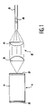
- FIG. 1 is a diagram representing an embodiment of the invention.
- FIG. 2 is a set of three pairs of curves, each pair representing the gain and losses of the laser cavity.
- the pair of curves A represents the gain and losses of the laser cavity at 25° C.
- the pair of curves B and C represent the gain and losses of the laser cavity at 70° C. and ⁇ 25° C. respectively.
- FIG. 1 diagrammatically shows a laser cavity 1 laid out in a manner known per se such that the direction of the emitted laser beam is controlled by focusing optical means 2 into an optical fiber 5 comprising a fiber grating 6 in a known manner.
- the laser 1 may be composed of a laser diode comprising an epitaxied quantum well structure, in a known manner as described for example in the patent mentioned above U.S. Pat. No. 5,715,263, or an InGaAs semiconducting medium between a reflecting mirror 8 and an output face 9 with a reflection coefficient that is very low compared with the reflection coefficient of the mirror 8 .
- the laser cavity is formed between mirrors 8 and 9 .
- the optical focusing means are composed of a first collimation lens 3 followed by a focusing lens 4 that focuses light towards the center of the fiber 5 , in a known manner.
- the value of the reflection coefficient of the output face 9 is typically 0.1% whereas the value of the reflection coefficient of the grating 6 is typically of the order of 1%, and in any case remains less than or equal to 5%.
- the emission frequency of the laser within the range authorized by the medium is determined by the reflection wavelength of the grating.
- the result is very good operating stability.
- the first noticeable fact is that there is practically no deformation in curve 11 representing losses, and all that happens is that the value of ⁇ is slightly shifted.
- the gains curve 10 shows a small positive slope for small values of the wavelength, and is then equal to a maximum, and then has a steep negative slope. This is satisfied for the three temperatures shown. It can be seen that for increasing temperatures, the maximum shifts by a relatively large amount towards increasing values of the wavelength, and that the maximum increases with temperature such that the length of the line with a positive slope increases.
- the inventors chose a value of the reflection wavelength ⁇ of the grating 6 at the required median operating temperature, equal to about 13 nm less than the value of the wavelength at the maximum on the gain curve 10 at the same temperature.
- the required operating range is ⁇ 20° C. to +70° C. Therefore, the median temperature of this range is 25° C.
- the minimum temperature in the range and shown in part C in FIG. 2 there is still an operating point at the maximum on curve 10 located at a value of the wavelength close to the reflection wavelength ⁇ of the grating 6 at this temperature.
- the laser operates well within the required temperature range.
- the laser according to the invention may be used for the same purposes as described in prior art as mentioned above, and particularly to pump a power laser composed of a fiber doped with erbium.
Abstract
Description
-
- means of coupling the laser output to an optical fiber,
- the optical fiber with a fiber grating returning a fraction of the light received from the laser through the fiber, to the laser cavity through coupling means.
-
- a quantum well laser with a laser cavity formed by a laser medium between a reflection face and an output face reflecting part of the light energy to the cavity, the curve representing the gain of the cavity as a function of the wavelength having a positive slope for increasing wavelengths, a maximum for a wavelength λmax and then a negative slope,
- means of coupling the laser output to an optical fiber, the optical fiber having a fiber grating defining a coefficient of a reflection peak for a wavelength λ and reflecting a fraction of the light received from the laser through the fiber, to the laser cavity through coupling means,
- device characterized in that the value of the wavelength λ defining the reflection peak of the fiber Bragg grating is less than the value of the wavelength λmax by at least 10 nanometers.
Claims (16)
Applications Claiming Priority (1)
| Application Number | Priority Date | Filing Date | Title |
|---|---|---|---|
| FR9905528A FR2793077B1 (en) | 1999-04-30 | 1999-04-30 | LASER WITH EXTENDED OPERATING TEMPERATURE RANGE |
Publications (1)
| Publication Number | Publication Date |
|---|---|
| US6952437B1 true US6952437B1 (en) | 2005-10-04 |
Family
ID=9545096
Family Applications (1)
| Application Number | Title | Priority Date | Filing Date |
|---|---|---|---|
| US09/550,596 Expired - Lifetime US6952437B1 (en) | 1999-04-30 | 2000-04-17 | Laser with wide operating temperature range |
Country Status (7)
| Country | Link |
|---|---|
| US (1) | US6952437B1 (en) |
| EP (1) | EP1049220B1 (en) |
| JP (1) | JP2000332352A (en) |
| AT (1) | ATE433217T1 (en) |
| CA (1) | CA2306318A1 (en) |
| DE (1) | DE60042293D1 (en) |
| FR (1) | FR2793077B1 (en) |
Cited By (5)
| Publication number | Priority date | Publication date | Assignee | Title |
|---|---|---|---|---|
| US20050018741A1 (en) * | 2002-10-18 | 2005-01-27 | Toshio Nomaguchi | Semiconductor laser |
| US20080144680A1 (en) * | 2004-05-25 | 2008-06-19 | Jeong Yong D | Single Mode Light Source Device Having External Cavity |
| US20140362886A1 (en) * | 2013-06-07 | 2014-12-11 | Ngk Insulators, Ltd. | External Resonator Type Light Emitting System |
| US9331454B2 (en) | 2013-11-27 | 2016-05-03 | Ngk Insulators, Ltd. | External resonator type light emitting system |
| US10063034B2 (en) | 2013-11-27 | 2018-08-28 | Ngk Insulators, Ltd. | External resonator-type light emitting device |
Citations (6)
| Publication number | Priority date | Publication date | Assignee | Title |
|---|---|---|---|---|
| US5485481A (en) * | 1994-06-28 | 1996-01-16 | Seastar Optics Inc. | Fibre-grating-stabilized diode laser |
| US5563732A (en) | 1994-01-06 | 1996-10-08 | At&T Corp. | Laser pumping of erbium amplifier |
| EP0772267A1 (en) | 1995-10-31 | 1997-05-07 | Nec Corporation | Laser diode device |
| US5717711A (en) * | 1995-11-21 | 1998-02-10 | Alcatel Optronics | Laser device, notably for optical pumping, and method of fabricating it |
| US6240119B1 (en) * | 1996-03-25 | 2001-05-29 | Sdl, Inc. | Apparatus for providing a stabilized laser source |
| US6343088B1 (en) * | 1998-01-26 | 2002-01-29 | The Furukawa Electric Co., Ltd. | Semiconductor laser module |
Family Cites Families (1)
| Publication number | Priority date | Publication date | Assignee | Title |
|---|---|---|---|---|
| JPH09148660A (en) * | 1995-11-24 | 1997-06-06 | Mitsubishi Electric Corp | Semiconductor laser equipment and optical amplifier |
-
1999
- 1999-04-30 FR FR9905528A patent/FR2793077B1/en not_active Expired - Fee Related
-
2000
- 2000-04-14 JP JP2000113011A patent/JP2000332352A/en not_active Withdrawn
- 2000-04-17 US US09/550,596 patent/US6952437B1/en not_active Expired - Lifetime
- 2000-04-18 CA CA002306318A patent/CA2306318A1/en not_active Abandoned
- 2000-04-25 DE DE60042293T patent/DE60042293D1/en not_active Expired - Lifetime
- 2000-04-25 EP EP00401137A patent/EP1049220B1/en not_active Expired - Lifetime
- 2000-04-25 AT AT00401137T patent/ATE433217T1/en not_active IP Right Cessation
Patent Citations (8)
| Publication number | Priority date | Publication date | Assignee | Title |
|---|---|---|---|---|
| US5563732A (en) | 1994-01-06 | 1996-10-08 | At&T Corp. | Laser pumping of erbium amplifier |
| US5485481A (en) * | 1994-06-28 | 1996-01-16 | Seastar Optics Inc. | Fibre-grating-stabilized diode laser |
| US5715263A (en) | 1994-06-28 | 1998-02-03 | Sdl, Inc. | Fibre-grating-stabilized diode laser |
| US6233259B1 (en) * | 1994-06-28 | 2001-05-15 | Sdl, Inc. | Fiber grating stabilized diode laser |
| EP0772267A1 (en) | 1995-10-31 | 1997-05-07 | Nec Corporation | Laser diode device |
| US5717711A (en) * | 1995-11-21 | 1998-02-10 | Alcatel Optronics | Laser device, notably for optical pumping, and method of fabricating it |
| US6240119B1 (en) * | 1996-03-25 | 2001-05-29 | Sdl, Inc. | Apparatus for providing a stabilized laser source |
| US6343088B1 (en) * | 1998-01-26 | 2002-01-29 | The Furukawa Electric Co., Ltd. | Semiconductor laser module |
Non-Patent Citations (1)
| Title |
|---|
| Patent Abstracts of Japan, vol. 1997, No. 10, Oct. 31, 1997, JP 09-148660, Jun. 06, 1997. |
Cited By (8)
| Publication number | Priority date | Publication date | Assignee | Title |
|---|---|---|---|---|
| US20050018741A1 (en) * | 2002-10-18 | 2005-01-27 | Toshio Nomaguchi | Semiconductor laser |
| US7103081B2 (en) * | 2002-10-18 | 2006-09-05 | Sumitomo Electric Industries, Ltd. | DFB laser with ar coating selected to provide wide temperature range of operation |
| US20080144680A1 (en) * | 2004-05-25 | 2008-06-19 | Jeong Yong D | Single Mode Light Source Device Having External Cavity |
| US20140362886A1 (en) * | 2013-06-07 | 2014-12-11 | Ngk Insulators, Ltd. | External Resonator Type Light Emitting System |
| US9184564B2 (en) * | 2013-06-07 | 2015-11-10 | Ngk Insulators, Ltd. | External resonator type light emitting system |
| US9627853B2 (en) | 2013-06-07 | 2017-04-18 | Ngk Insulators, Ltd. | External resonator-type light emitting device |
| US9331454B2 (en) | 2013-11-27 | 2016-05-03 | Ngk Insulators, Ltd. | External resonator type light emitting system |
| US10063034B2 (en) | 2013-11-27 | 2018-08-28 | Ngk Insulators, Ltd. | External resonator-type light emitting device |
Also Published As
| Publication number | Publication date |
|---|---|
| FR2793077A1 (en) | 2000-11-03 |
| EP1049220B1 (en) | 2009-06-03 |
| DE60042293D1 (en) | 2009-07-16 |
| EP1049220A1 (en) | 2000-11-02 |
| JP2000332352A (en) | 2000-11-30 |
| CA2306318A1 (en) | 2000-10-30 |
| FR2793077B1 (en) | 2001-07-27 |
| ATE433217T1 (en) | 2009-06-15 |
Similar Documents
| Publication | Publication Date | Title |
|---|---|---|
| US6233259B1 (en) | Fiber grating stabilized diode laser | |
| EP0305995B1 (en) | An optical amplifying repeater | |
| EP1107404B1 (en) | Fibre grating stabilized diode laser | |
| US8175127B2 (en) | System of method for dynamic range extension | |
| US7693194B2 (en) | Fundamental-wave light source and wavelength converter | |
| US6614823B2 (en) | Semiconductor laser device having a diffraction grating on a light reflection side | |
| Faugeron et al. | High Power Three-Section Integrated Master Oscillator Power Amplifier at 1.5$\mu\text {m} $ | |
| US6816531B1 (en) | High-power, kink-free, single mode laser diodes | |
| US20030035449A1 (en) | Laser systems | |
| EP1619764A1 (en) | System and method for dynamic range extension and stable low power operation of optical amplifiers using pump laser pulse modulation | |
| EP0656675B1 (en) | Laser-diode-pumped solid-state laser using index-guided type multi-transverse mode broad area laser | |
| US6704338B2 (en) | Semiconductor laser device, semiconductor laser module, and semiconductor laser control method | |
| EP1067644B1 (en) | Semiconductor laser module | |
| WO1984000857A1 (en) | Spectrally stabilized laser | |
| US6952437B1 (en) | Laser with wide operating temperature range | |
| EP1241751B1 (en) | High power, kink-free, single mode laser diodes | |
| US6400736B1 (en) | Wavelength stabilized laser modules | |
| US7099072B2 (en) | Direct optical modulation type wavelength converter | |
| Bissessur et al. | Wavelength-versatile external fiber grating lasers for 2.5-Gb/s WDM networks | |
| EP3392986B1 (en) | Tunable laser and controlling method therefor | |
| US20020097772A1 (en) | Stabilized optical pump laser | |
| US5119039A (en) | Semiconductor optical amplifier with wideband electrical response | |
| KR100617686B1 (en) | Gain clamped semiconductor optical amplifier | |
| JPH11214802A (en) | Fiber diffraction-grating stabilizing diode laser | |
| JPH02152289A (en) | Optical amplifier device |
Legal Events
| Date | Code | Title | Description |
|---|---|---|---|
| AS | Assignment |
Owner name: ALCATEL, FRANCE Free format text: ASSIGNMENT OF ASSIGNORS INTEREST;ASSIGNORS:BETTIATI, MAURO;GELLY, GERARD;REEL/FRAME:011055/0630 Effective date: 20000630 |
|
| AS | Assignment |
Owner name: AVANEX CORPORATION, CALIFORNIA Free format text: ASSIGNMENT OF ASSIGNORS INTEREST;ASSIGNOR:ALCATEL;REEL/FRAME:013995/0729 Effective date: 20030731 |
|
| AS | Assignment |
Owner name: HBK INVESTMENTS L.P., TEXAS Free format text: SECURITY AGREEMENT;ASSIGNOR:AVANEX CORPORATION;REEL/FRAME:016079/0174 Effective date: 20050519 |
|
| STCF | Information on status: patent grant |
Free format text: PATENTED CASE |
|
| AS | Assignment |
Owner name: AVANEX CORPORATION, CALIFORNIA Free format text: RELEASE BY SECURED PARTY;ASSIGNOR:HBK INVESTMENTS, L.P.;REEL/FRAME:019035/0342 Effective date: 20070312 |
|
| FPAY | Fee payment |
Year of fee payment: 4 |
|
| AS | Assignment |
Owner name: WELLS FARGO CAPITAL FINANCE, INC., AS AGENT, CALIF Free format text: PATENT SECURITY AGREEMENT;ASSIGNOR:OCLARO (NORTH AMERICA), INC.;REEL/FRAME:028540/0413 Effective date: 20110726 |
|
| FPAY | Fee payment |
Year of fee payment: 8 |
|
| AS | Assignment |
Owner name: OCLARO (NORTH AMERICA), INC., CALIFORNIA Free format text: CHANGE OF NAME;ASSIGNOR:AVANEX CORPORATION;REEL/FRAME:032174/0375 Effective date: 20090701 |
|
| AS | Assignment |
Owner name: OCLARO SWITZERLAND GMBH, SWITZERLAND Free format text: ASSIGNMENT OF ASSIGNORS INTEREST;ASSIGNORS:OCLARO, INC.;OCLARO TECHNOLOGY LIMITED;OCLARO TECHNOLOGY, INC.;AND OTHERS;REEL/FRAME:032250/0324 Effective date: 20130912 |
|
| AS | Assignment |
Owner name: II-VI LASER ENTERPRISE GMBH, SWITZERLAND Free format text: CHANGE OF NAME;ASSIGNOR:OCLARO SWITZERLAND GMBH;REEL/FRAME:032251/0069 Effective date: 20131008 |
|
| AS | Assignment |
Owner name: OCLARO, INC., CALIFORNIA Free format text: RELEASE OF SECURITY INTEREST;ASSIGNOR:WELLS FARGO CAPITAL FINANCE, LLC;REEL/FRAME:033100/0451 Effective date: 20130912 Owner name: OCLARO TECHNOLOTY LIMITED, CALIFORNIA Free format text: RELEASE OF SECURITY INTEREST;ASSIGNOR:WELLS FARGO CAPITAL FINANCE, LLC;REEL/FRAME:033100/0451 Effective date: 20130912 |
|
| FPAY | Fee payment |
Year of fee payment: 12 |